

Page 1
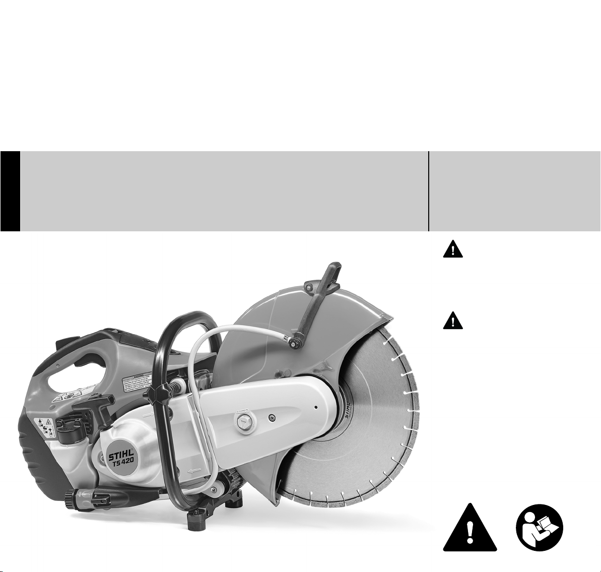
STIHL TS 410, 420
WARNING
Read Instruction Manual thoroughly
before use and follow all safety
precautions – improper use can
cause serious or fatal injury.
ADVERTENCIA
Antes de usar la máquina lea y siga
todas las precauciones de
seguridad dadas en el manual de
instrucciones – el uso incorrecto
puede causar lesiones graves o
mortales.
{
Instruction Manual
Manual de instrucciones
Page 2

Instruction Manual
1 - 50
Manual de instrucciones
51 - 106
Page 3

Contents
English
Guide to Using this Manual 2
Safety Precautions and Working
Techniques 3
Sample applications 16
Cutting wheels 20
Composite resin cutting wheels 20
Diamond cutting wheels 21
Electronic water control 24
Original Instruction ManualPrinted on chlorine-free paper
Assembling the cast arm and guard 25
Tensioning the ribbed V-belt 29
Fitting / replacing an abrasive
wheel 29
Fuel 31
Fueling 32
Starting / Stopping the Engine 33
Air Filter System 35
Engine Management 36
Adjusting the Carburetor 37
Spark Arresting Screen in Muffler 38
Spark Plug 38
Rewind Starter 40
Replacing the V-belt 40
Printing inks contain vegetable oils, paper can be recycled.
Cut-off machine cart 41
Storing the Machine 41
Maintenance and Care 42
Main Parts 44
Specifications 46
Maintenance and Repairs 47
Disposal 47
STIHL Incorporated Federal
Emission Control Warranty
Statement 48
Trademarks 50
Allow only persons who fully understand
this manual to operate your cut-off
machine.
To receive maximum performance and
satisfaction from your STIHL Cutquik
cut-off machine, it is important that you
read, understand and follow the safety
precautions and the operating and
maintenance instructions in the chapter
"Safety Precautions and Working
Techniques" before using your cut-off
machine. For further information you can
go to www.stihlusa.com
Contact your STIHL dealer or the STIHL
distributor for your area if you do not
understand any of the instructions in this
manual.
WARNING
Because a cut-off machine is a highspeed cutting tool, some special safety
precautions must be observed to reduce
the risk of personal injury. Careless or
improper use may cause serious or even
fatal injury.
{
© ANDREAS STIHL AG & Co. KG, 2014
0458-370-8621-G. VB2.K14.
0000000893_014_GB
TS 410, TS 420
This instruction manual is protected by copyright. All rights reserved, especially the rights to reproduce, translate and process
with electronic systems.
1
Page 4
English
Guide to Using this Manual
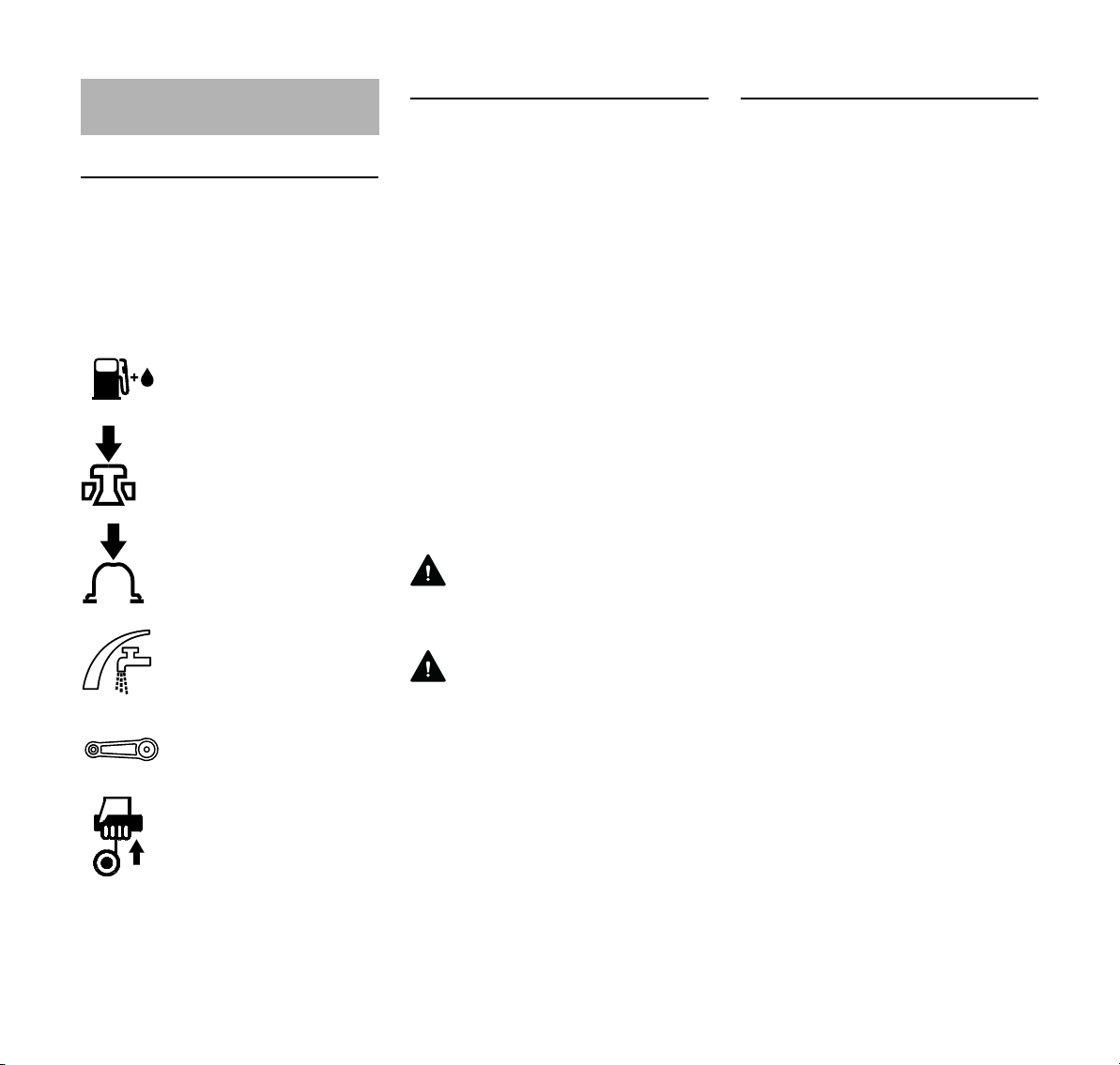
Pictograms
The meanings of the pictograms
attached to or embossed on the
machine are explained in this manual.
Depending on the model concerned, the
following pictograms may be on your
machine.
Fuel tank for gasoline
and engine oil mixture
Press to operate decom
pression valve
Press to operate manual
fuel pump
Water attachment, flow
control
Tensioning nut for engag
ing drive belt
Symbols in Text
Many operating and safety instructions
are supported by illustrations.
The individual steps or procedures
described in the manual may be marked
in different ways:
N A bullet marks a step or procedure.
A description of a step or procedure that
refers directly to an illustration may
contain item numbers that appear in the
illustration. Example:
N Loosen the screw (1).
N Lever (2) ...
-
In addition to the operating instructions,
this manual may contain paragraphs
that require your special attention. Such
paragraphs are marked with the
symbols and signal words described
below:
DANGER
Indicates an imminent risk of severe or
fatal injury.
WARNING
Indicates a hazardous situation which, if
-
not avoided, could result in severe or
fatal injury.
Engineering Improvements
STIHL’s philosophy is to continually
improve all of its products. As a result,
engineering changes and improvements
are made from time to time. Therefore,
some changes, modifications and
improvements may not be covered in
this manual. If the operating
characteristics or the appearance of
your machine differs from those
described in this manual, please contact
your STIHL dealer or the STIHL
distributor for your area for assistance.
Pull starter grip
2
Indicates a risk of property damage,
including damage to the machine or its
individual components.
TS 410, TS 420
NOTICE
Page 5
English
Safety Precautions and
Working Techniques
The use of any cut-off
machine may be hazard
ous. Because a cut-off
machine is a high-speed,
fast-cutting power tool,
special safety precau
tions must be observed to
reduce the risk of per
sonal injury and fire.
It is important that you
read, fully understand
and observe the following
safety precautions and
warnings. Read the
instruction manual and
the safety precautions
periodically.
WARNING
Careless or improper use of any cut-off
machine may cause serious or fatal
injury.
Have your STIHL dealer show you how
to operate your cut-off machine.
Observe all applicable national, state
and local safety regulations, standards
and ordinances.
WARNING
Your cut-off machine is for professional
use only. Do not lend or rent your cut-off
machine without the instruction manual.
Be sure that anyone using it
understands the information contained
in this manual.
-
-
A first-time operator should obtain
practical instruction before using the
machine. Employers should establish a
training program for operators of
gasoline-powered, hand-held portable
-
cut-off machines to assure safe
operation of these machines and proper
choice of cutting attachments. These
safety precautions and warnings apply
to the use of all current STIHL Cutquiks.
WARNING
Use your cut-off machine only for
authorized uses. For instance, it is not
suitable for cutting wood or wooden
objects. Misuse may result in personal
injury or property damage, including
damage to the machine.
WARNING
Minors should never be allowed to use a
cut-off machine. Bystanders, especially
children, and animals should not be
allowed in the area where a cut-off
machine is in use. Never let the cut-off
machine run unattended.
Different models may have different
parts and controls. See the appropriate
section of your instruction manual for a
description of the controls and function
of the parts of your model cut-off
machine.
Safe use of a cut-off machine involves
1. the operator
2. the power tool
3. the use of the power tool.
THE OPERATOR
Physical Condition
You must be in good physical condition
and mental health and not under the
influence of any substance (drugs,
alcohol, etc.) which might impair vision,
dexterity or judgment. Do not operate a
cut-off machine when you are fatigued.
Be alert – if you get tired while operating
your cut-off machine, take a break;
tiredness may result in loss of control.
Working with any cut-off machine can be
strenuous. If you have any condition that
might be aggravated by strenuous work,
check with your doctor before operating
a cut-off machine.
WARNING
Prolonged use of cut-off machines (or
other machines) exposing the operator
to vibrations may produce whitefinger
disease (Raynaud's phenomenon) or
carpal tunnel syndrome. These
conditions reduce the hand's ability to
feel and regulate temperature, produce
numbness and burning sensations and
cause nerve and circulation damage and
tissue necrosis. All factors which
contribute to whitefinger disease are not
known, but cold weather, smoking and
diseases or physical conditions that
affect blood vessels and blood transport,
as well as high vibration levels and long
periods of exposure to vibration are
mentioned as factors in the development
of whitefinger disease. In order to
reduce the risk of whitefinger disease
and carpal tunnel syndrome, please
note the following:
TS 410, TS 420
3
Page 6
English
– STIHL cut-off machines are
equipped with an anti-vibration
("AV") system designed to reduce
the transmission of vibrations
created by the machine to the
operator's hands. An AV system is
recommended for those persons
using cut-off machines on a regular
or sustained basis.
– Wear gloves and keep your hands
warm.
– Keep the AV system well
maintained. A cut-off machine with
loose components or with damaged
or worn AV elements will tend to
have higher vibration levels.
– Maintain a firm grip at all times, but
do not squeeze the handles with
constant, excessive pressure. Take
frequent breaks.
All the above-mentioned precautions do
not guarantee that you will not sustain
whitefinger disease or carpal tunnel
syndrome. Therefore, continual and
regular users should monitor closely the
condition of their hands and fingers. If
any of the above symptoms appear,
seek medical advice immediately.
WARNING
The ignition system of your unit
produces an electromagnetic field of a
very low intensity. This field may
interfere with some pacemakers. To
reduce the risk of serious or fatal injury,
persons with a pacemaker should
consult their physician and the
pacemaker manufacturer before
operating this tool.
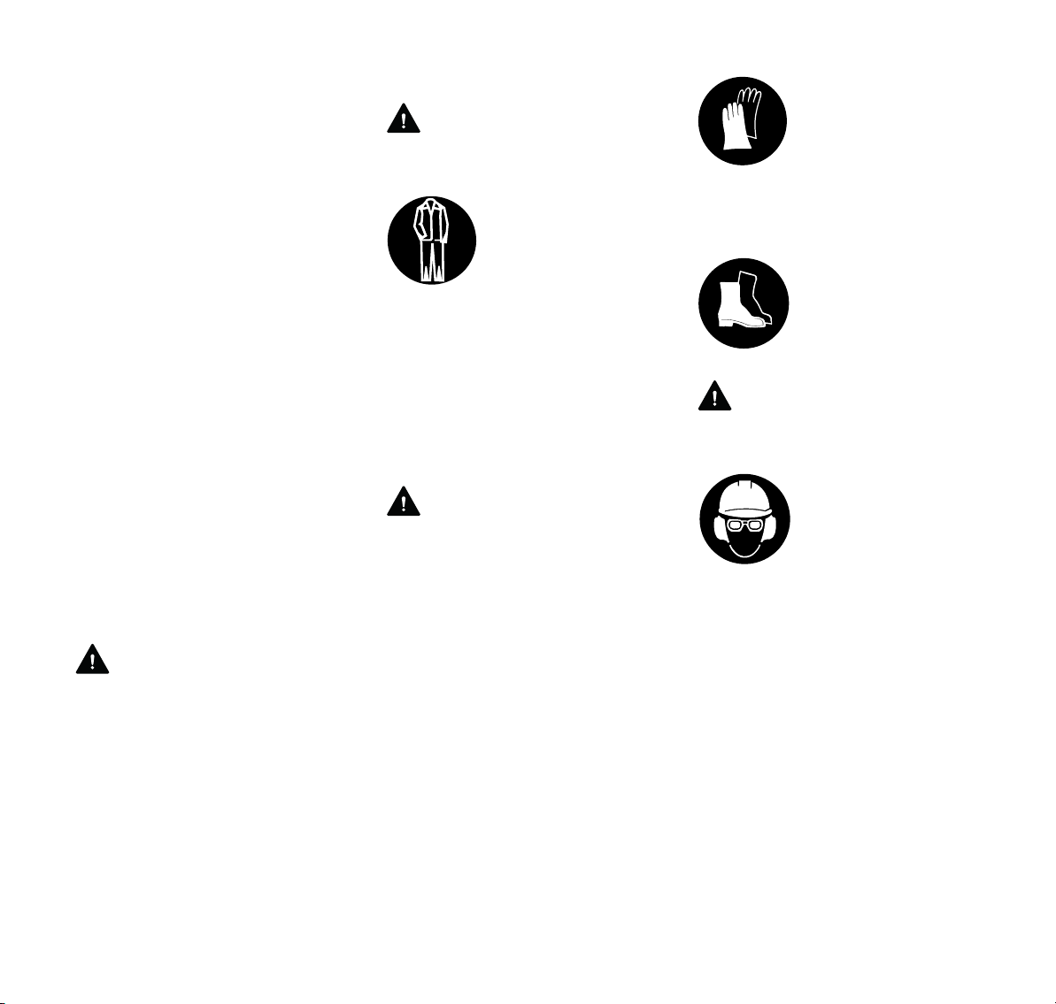
Proper Clothing
WARNING
To reduce the risk of injury, the operator
should wear proper protective apparel.
Clothing must be sturdy
and snug-fitting, but allow
complete freedom of
movement. Avoid loosefitting jackets, scarfs,
neckties, jewelry, flared
or cuffed pants, uncon
fined long hair or
anything that could
become caught on any
obstacles or moving parts
of the unit. Wear overalls
or long pants to protect
your legs. Do not wear
shorts.
WARNING
When cutting metal, a cut-off machine
generates sparks that can ignite
clothing. Most fabrics used in clothing
are flammable – even flame-retardant
fabrics will ignite at higher temperatures.
To reduce the risk of burn injury STIHL
recommends wearing clothing made of
leather, wool, flame-retardant-treated
cotton or a tightly woven, heavier cotton
such as denim. Some flame-retardant
synthetic fabrics are also suitable, but
others such as polyester, nylon, rayon
and acetate can melt during a fire into a
tar-like matter that burns into the skin.
Check the clothing manufacturer's
instructions. Keep clothing free of oil,
fuel, grease and other flammable
substances.
-
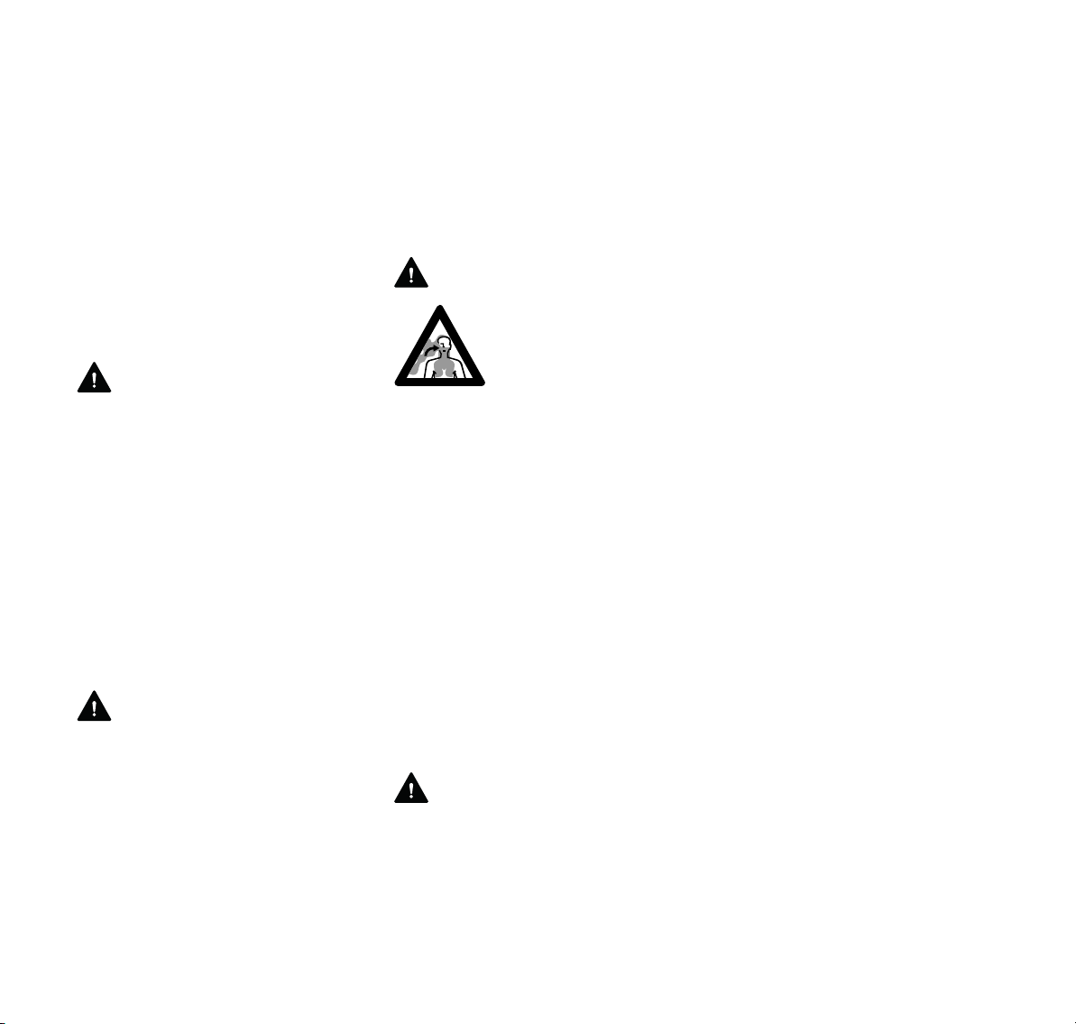
Always wear heavy duty
work gloves (e.g. made of
leather or other wear
resistant material) when
handling the cutt-off
machine. Heavy-duty,
nonslip gloves improve
your grip and help to pro
tect your hands.
Good footing is important
in cut-off machine work.
Wear sturdy boots with
nonslip soles. Steel-toed
safety boots are
recommended.
WARNING
Loose objects may be thrown toward the
operator by the cutting tool.
To reduce the risk of
injury to your eyes never
operate a cut-off machine
unless wearing goggles
or properly fitted safety
glasses with adequate
top and side protection
complying with
ANSI Z87 "+". Proper eye
protection is a must.
Wear an approved safety hard hat to
protect your head. Cut-off machine
noise may damage your hearing. Always
wear sound barriers (ear plugs or ear
mufflers) to help protect your hearing.
Regular users should have their hearing
checked regularly.
-
4
TS 410, TS 420
Page 7
English
WARNING
When wet cutting at the
recommended flow rate
is not utilized, the opera
tor should always wear a
respirator approved by
NIOSH/MSHA for the
material being cut to
reduce the risk of serious
or fatal respiratory illness.
For additional details and
warnings on this subject,
see information under
"Working Conditions" in
this instruction manual.
THE POWER TOOL
For illustrations and definitions of the
parts of the cut-off machine, see the
chapter "Main Parts."
WARNING
Never modify a cut-off machine in any
way. Only STIHL branded parts and
cutting attachments expressly approved
by STIHL for use with the specific STIHL
cut-off machine models are
recommended. Although certain other
parts or attachments may be useable
with the STIHL powerhead, their use
may, in fact, be extremely dangerous.
Abrasive Wheels
WARNING
Before mounting the cutting wheel,
make sure that the maximum operating
wheel speed is above or equal to the
spindle speed of your cut-off machine as
provided in the specifications of this
manual. A wheel that is not so rated may
shatter or break and poses a threat of
serious or fatal injury to the operator and
other nearby persons.
-
Abrasive wheels for free-hand cutting
are subjected to particularly high
bending and compression stresses.
WARNING
Never use a reducer bushing inserted
into the wheel to reduce the diameter of
the arbor hole. It may slip out of place,
causing out-of-roundness, vibration and
wheel breakage.
WARNING
Wheels that are not STIHL branded may
be more likely to shatter or break or
create other hazards, such as increased
reactive forces. Use only wheels with
approved RPM ratings. Read and follow
any addional safety precautions that
accompany the wheel.
WARNING
Inspect the abrasive
wheel frequently and
replace immediately if the
abrasive wheel is
cracked or warped.
Cracked or warped
wheels may shatter or
break and cause serious
or fatal personal injury.
Out-of-round or unbal
anced abrasive wheels
increase vibration and
reduce the service life of
the cut-off machine.
Some diamond abrasive wheels that are
not STIHL branded utilize poor quality
steel cores, are not properly tensioned,
or have other design or manufacturing
defects. As a result, they may begin to
wobble during use, which can cause
wheel breakage. Such wobbling can
also lead to a severe binding of the
wheel in the kerf, that, under certain
circumstances, can then result in
serious or fatal injury from reactive
forces. See the section entitled
"Reactive Forces including Kickback."
Never use a wheel that wobbles or that
has ever wobbled. Even though such a
wheel may temporarily cease to wobble,
e.g., if run without load, it will always be
prone to wobble again under certain
conditions. Replace it immediately
before further use.
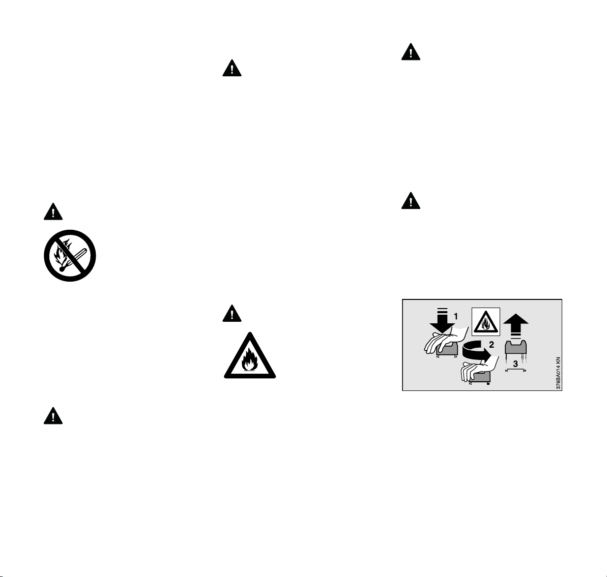
Composite abrasive wheels are heat
sensitive. Always store your cut-off
machine in a place where a composite
wheel is not exposed to direct sunlight or
other sources of heat. Store spare
composite wheels flat on a level surface
in a dry place where there is no risk of
frost damage. Failure to follow these
directions may cause the wheel to
shatter or crack in use causing serious
or fatal injury.
-
TS 410, TS 420
5
Page 8
English
WARNING
Never use circular saw
blades, carbide tipped
blades, rescue blades,
wood-cutting blades or
toothed blades of any
nature. They can cause
severe personal injury
from blade contact,
thrown objects and/or
reactive forces, including
kickback. See section on
"Reactive Forces." Your
STIHL dealer stocks a
range of special abrasive
wheels for the many
applications of the cut-off
machine.
WARNING
Use of the wrong abrasive wheel or the
cutting of material for which the wheel
was not designed may cause the wheel
to wobble, shatter or increase reactive
forces, causing serious or fatal injury.
See below and section "Reactive
Forces."
Only use the abrasive wheel approved
for the type of material to be cut. There
are different types of abrasive wheels,
each specially marked. With respect to
STIHL composite wheels, for example:
1. Stone
Also can be used for concrete,
masonry, reinforced concrete and
brick cutting.
2. Steel
Can be used for all ferrous metal
cutting.
3. Asphalt
Also can be used for aggregate
concrete cutting.
4. Ductile iron
Also can be used for certain grades
of cast iron (SG 17-24), bronze and
copper cutting.
For cutting composite materials please
ask your STIHL dealer.
Diamond Abrasive Wheels
Diamond abrasive wheels have a much
better cutting performance than
composite abrasive wheels. The
diamond wheels are steel centered, and
diamond particles are imbedded in their
cutting edges.
They can be used for concrete, asphalt,
natural stone, clay pipe, brick and the
like. STIHL also offers diamond wheels
for cutting ductile iron and some
structural steel.
They are not, however, suitable for
cutting all metals and other materials.
Wet or dry cutting is possible. Water
attachments are included with your
STIHL cut-off machine. See the
appropriate section of your instruction
manual.
WARNING
Do not remount a used diamond
abrasive wheel without first inspecting
for under-cutting, flatness, core fatigue,
segment damage or loss, signs of
overheating (discoloration) and possible
arbor hole damage. See the chapter
"Diamond Cutting Wheels." Check the
wheel for cracks and make sure that no
pieces have broken off the wheel before
use.
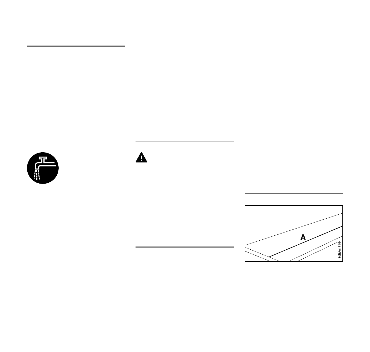
Always fit the wheel so that the arrow on
the wheel points in the direction of the
rotation of the spindle.
THE USE OF THE POWER TOOL
Transporting the STIHL Cutquik
WARNING
To reduce the risk of injury from
unintended activation and/or contact
with a moving wheel, always stop the
engine before putting a cut-off machine
down or carrying it. The abrasive wheel
continues to rotate (coast down) for a
short while after the throttle trigger is
released (flywheel effect). Bring the
wheel to a stop by lightly contacting the
bottom of the wheel with a hard surface
or wait until the wheel comes to a
complete stop on its own. Carrying a cutoff machine with the engine running is
extremely dangerous. Accidental
acceleration of the engine can cause the
wheel to rotate. Avoid touching the hot
muffler.
By hand: When carrying your cut-off
machine by hand, the engine must be
stopped and the cut-off machine must
be in the proper position. Grip the front
handle and place the muffler at the side
away from the body with the cutting
attachment to the rear.
WARNING
Always protect the cutting wheel from
hitting the ground or any other objects.
Damaged wheels may shatter and
cause serious or fatal injury.
6
TS 410, TS 420
Page 9
English
By vehicle: Properly secure your cut-off
machine to prevent turnover, fuel
spillage and damage to the cut-off
machine. Never transport with cutting
wheel mounted. A wheel damaged
during transportation may shatter during
operation and cause serious personal
injury.
Fuel
Your STIHL power tool uses an oil-
gasoline mixture for fuel (see the
chapter on "Fuel" of your instruction
manual.)
WARNING
Gasoline is an extremely
flammable fuel. If spilled
and ignited by a spark or
other ignition source, it
can cause fire and seri
ous burn injury or
property damage. Use
extreme caution when
handling gasoline or fuel
mix. Do not smoke or
bring any fire or flame
near the fuel or the power
tool. Note that combusti
ble fuel vapor may
escape from the fuel
system.
WARNING
Dust may collect on the powerhead,
especially around the carburetor, and
may absorb gasoline resulting in a risk of
fire. Clean dust from the powerhead
regularly.
-
-
Fueling Instructions
WARNING
Fuel your power tool in well-ventilated
areas, outdoors. Always shut off the
engine and allow it to cool before
refueling. Gasoline vapor pressure may
build up inside the fuel tank depending
on the fuel used, the weather conditions
and the tank venting system.
In order to reduce the risk of burns and
other personal injury from escaping gas
vapor and fumes, remove the fuel filler
cap on your power tool carefully so as to
allow any pressure build-up in the tank
to release slowly. Never remove the fuel
filler cap while the engine is running.
Select bare ground for fueling and move
at least 10 feet (3 m) from the fueling
spot before starting the engine. Wipe off
any spilled fuel before starting your
machine.
WARNING
Check for fuel leakage
while refueling and during
operation. If fuel leakage
is found, do not start or
run the engine until the
leak is fixed and any
spilled fuel has been
wiped away. Take care
not to get fuel on your
clothing. If this happens,
change your clothing
immediately.
WARNING
If fuel gets spilled on clothes, especially
trousers, it is very important to change
clothes immediately. Do not rely upon
evaporation. Flammable quantities of
fuel may remain on clothes after a spill
for longer than expected. Cutting metal
with a cut-off machine when clothes are
wet or damp from gasoline is extremely
dangerous, as the operator's clothes
might catch fire and cause serious or
fatal injury.
WARNING
An improperly tightened fuel cap can
loosen or come off and spill quantities of
fuel.
Different cut-off machines may be
equipped with different fuel filler caps:
Bayonet Fuel Filler Cap
Never use a tool to open or close the
bayonet fuel filler cap, as this could
damage the cap and cause fuel to leak
out.
The bayonet fuel filler cap must be
securely closed after refuelling.
TS 410, TS 420
7
Page 10
English
002BA058 KN
Fuel Filler Cap with Screw Thread
Tighten the fuel filler cap
as securely as possible
after refuelling.
This reduces the risk of the cap working
loose due to engine vibrations and fuel
leaking out.
WARNING
Never attempt to force the cap open by
using a tool. It may damage the cap and
allow fuel to leak.
WARNING
Before use, make sure that the fuel cap
has been completely and properly
tightened and any spilled fuel wiped
away. Check for fuel leakage while
refueling and during operation. If a fuel
leak is suspected, do not start or run the
engine until the leak is fixed and spilled
fuel has been wiped away.
Before Starting
For wheel installation, follow the
procedure described in the appropriate
sections of your instruction manual.
WARNING
Check fuel system for leaks, especially
the visible parts, e.g., filler cap, hose
connections, manual fuel pump (only for
power tools equipped with a manual fuel
pump). Do not start the engine if there
are leaks or damage – risk of fire! Have
the machine repaired by a servicing
dealer before using it.
WARNING
Never operate a cut-off machine if it is
damaged, improperly adjusted or
maintained, or not completely or
securely assembled. Check machine
that it is ready for proper operation.
Keep the handles dry, clean and free of
oil and fuel.
WARNING
Before operation of your cut-off
machine, be sure the controls (e.g.
throttle trigger, throttle trigger lockout,
stop switch) and the safety devices are
working properly, the carburetor idle and
maximum speed are correctly adjusted,
the wheel is properly mounted, and the
wheel guard is in place and securely
fastened to your unit. All wheels should
be carefully inspected for good condition
before mounting.
Adjust the wheel guard
so that sparks, dust and
cut material are deflected
away from the operator,
and cannot reach flam
-
mable surroundings. See
section "Operating
Instructions" of your
instruction manual.
WARNING
Check that the spark plug boot is
securely mounted on the spark plug – a
loose boot may cause arcing that could
ignite combustible fumes and cause a
fire.
Proper tensioning of the ribbed V-belt is
important. In order to avoid an incorrect
setting, the tensioning procedure must
be followed as described in your
manual. Always make sure the
hexagonal collar nuts for the cast arm
are tightened securely.
Check ribbed belt tension after one hour
of operation and correct if necessary.
Starting
WARNING
Your cut-off machine is a one-person
tool. Do not allow other persons to be
near a running cut-off machine. Start
and operate your cut-off machine
without assistance. For specific starting
instructions, see the appropriate section
of your instruction manual.
Do not drop start. This method is very
dangerous because you may lose
control of the cut-off machine. Place the
cut-off machine on firm ground or other
solid surface in an open area. Maintain
good balance and secure footing. Be
8
TS 410, TS 420
Page 11
English
absolutely sure that the cutting wheel is
clear of you and all other obstructions
and objects, including the ground. When
the engine starts at starting-throttle,
engine speed will be fast enough for the
clutch to engage the belt pulley and turn
the wheel. Never attempt to start the cutoff machine when the abrasive wheel is
in a cut.
Once the engine has started,
immediately blip the throttle trigger,
which should release the starting throttle
lock and allow the engine to slow down
to idle.
WARNING
When you pull the starter grip, do not
wrap the starter rope around your hand.
Do not allow the grip to snap back, but
guide the starter rope slowly back to
permit the rope to rewind properly.
Failure to follow this procedure may
result in injuries to hand or fingers and
may damage the starter mechanism.
Important Adjustments
At correct idle speed, the wheel should
not turn. For directions to adjust idle
speed, see the appropriate section of
your instruction manual.
WARNING
Do not use a cut-off machine with
incorrect idle speed adjustment. The
rotating wheel may cause injury. If you
cannot obtain the correct setting, have
your STIHL dealer check your cut-off
machine and make proper adjustments
or repairs.
Working Conditions
Operate the cut-off machine under good
visibility and daylight conditions only.
Wearing of hearing protection reduces
sound perception. Be alert not to miss
voice signals from co-workers. Keep
within calling distance to other persons
who may assist in case of emergency.
WARNING
As soon as the engine is
running, this product gen
erates toxic exhaust
fumes containing chemi
cals, such as unburned
hydrocarbons (including
benzene) and carbon
monoxide, that are
known to cause respira
tory problems, cancer,
birth defects, or other
reproductive harm. Some
of the gases (e.g. carbon
monoxide) may be color
less and odorless. To
reduce the risk of serious
or fatal injury/illness from
inhaling toxic fumes,
never run the machine
indoors or in poorly venti
lated locations. Ensure
proper ventilation when
working in trenches or
other confined areas.
WARNING
Use of this product to cut masonry,
concrete, metal and other materials can
generate dust and fumes containing
chemicals known to cause serious or
fatal injury or illness, such as respiratory
-
-
disease, cancer, birth defects or other
reproductive harm. If you are unfamiliar
with the risks associated with the
particular material being cut, review the
material safety data sheet and/or consult
your employer, the material
manufacturer/supplier, governmental
agencies such as OSHA and NIOSH
and other sources on hazardous
materials. California and some other
authorities, for instance, have published
lists of substances known to cause
cancer, reproductive toxicity, etc.
-
Control dust and fumes at the source
where possible.
In this regard use good work practices
and follow the recommendations of the
manufacturer/supplier, OSHA/NIOSH,
and occupational and trade
associations. A water attachment kit is
provided with your cut-off machine and
should be used to reduce dust whenever
wet cutting is feasible. For dust
suppression purposes, the flow rate
should be at least 0.6 liters (20 fl.oz) of
-
water per minute. If wet cutting at the
recommended flow rate is not utilized,
the operator and any bystanders should
always wear a respirator approved by
NIOSH/MSHA for the material being cut.
See the section on "Respiratory
-
Protection" in the chapter "Sample
Applications" in the instruction manual.
Even if wet cutting at the recommended
flow rate, an operator who is actively
cutting for more than two hours in one
day should wear at least a NIOSHapproved disposable respirator. Consult
and follow any federal, state or local
laws or regulations with respect to dry
and wet cutting.
TS 410, TS 420
9
Page 12
English
WARNING
Cutting masonry, concrete and other
materials with silica in their composition
may give off dust containing crystalline
silica. Silica is a basic component of
sand, quartz, brick clay, granite and
numerous other minerals and rocks.
Repeated and/or substantial inhalation
of airborne crystalline silica can cause
serious or fatal respiratory diseases,
including silicosis. In addition, California
and some other authorities have listed
respirable crystalline silica as a
substance known to cause cancer.
When cutting such materials, always
follow the respiratory precautions
mentioned above.
WARNING
Breathing asbestos dust is dangerous
and can cause severe or fatal injury,
respiratory illness or cancer. The use
and disposal of asbestos-containing
products have been strictly regulated by
OSHA and the Environmental Protection
Agency. Do not use your cut-off machine
to cut or disturb asbestos, asbestoscontaining products, or products such as
pipes which are wrapped or covered
with asbestos insulation. If you have any
reason to believe that you might be
cutting asbestos, immediately contact
your employer or a local OSHA
representative.
WARNING
Your STIHL cut-off machine is designed
for hand-held use or operation on a cutoff machine cart. Cutting with your cutoff machine resting on the ground or
other surface can cause excessive wear
to the bracket designed to protect the
bottom of the tank housing. Loss of fuel
and personal injury from fire may result.
Replace damaged or badly worn
brackets immediately.
Grip: Never use the cut-off machine with
one hand. Always hold the cut-off
machine firmly with both hands when the
engine is running. Place your left hand
on front handle bar and your right hand
on rear handle and throttle trigger. Lefthanded users should follow this
instruction too.
Wrap your fingers tightly around the
handles, keeping the handles cradled
between your thumbs and forefingers.
Make sure your cut-off machine handles
and grip are in good condition and free
of moisture, pitch, oil, fuel mix or grease.
Never touch a rotating wheel with your
hand or any part of your body.
WARNING
Clear the area where you are working.
Avoid stumbling on obstacles and watch
out for holes or ditches. Be extremely
cautious when working on slopes or
uneven ground. Take extreme care in
wet and freezing weather (rain, snow,
002BA549 AM
ice.)
WARNING
Never operate the cut-off machine with
the starting-throttle lock engaged as this
does not permit proper control of the
speed of the unit and may lead to
serious injury.
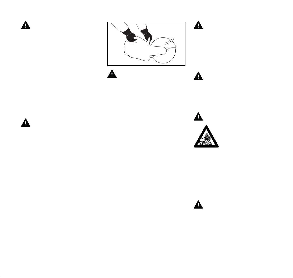
WARNING
Sparks from cutting metal
can burn or cause cloth
ing to catch fire. Always
direct sparks away from
the operator or any flam
mable surroundings.
Never cut metal while
standing on a flammable
surface, such as wood or
tar paper. Where there is
a risk of fire, have appro
priate fire extinguishing
equipment readily
available.
WARNING
To reduce the risk of injury from fire, do
not cut into any pipe, drum or other
container without first ensuring that it
does not contain a volatile or flammable
substance.
-
-
-
10
TS 410, TS 420
Page 13
English
WARNING
When cutting into existing walls, floors or
similar structures, be alert for hidden
hazards such as electrical cables, water
and gas pipes and flammable
substances. Make sure that power,
water and gas have been shut off and
pipes drained before starting to cut.
Operating Instructions
WARNING
The wheel guard is adjustable. It is
extremely important that the wheel
guard is in place and set to suit the type
of work and your stance. The guard
should always be adjusted so that the
user is not endangered by particles of
the material being cut, sparks or pieces
of damaged wheels either directly or by
ricochet. Failure to follow this instruction
could result in serious or fatal injury.
WARNING
Your cut-off machine is equipped with a
wheel guard limit stop that restricts the
positioning of the wheel guard. To
reduce the risk of injury from wheel
contact and/or reactive forces and to
avoid damaging the guarding system,
never attempt to pull the adjusting lever
past the limit stop.
WARNING
Always check the wheel before use and
after unintentionally striking any object;
frequently check it during use when it is
stopped. Look for cracks and make sure
that it is undamaged and in good
condition and that no pieces have
broken off. See sections on "Abrasive
Wheels" and "Reactive Forces" in this
manual. Check the wheel guard for
cracks. If you discover any breaks or
cracks, fit a new guard before further
use.
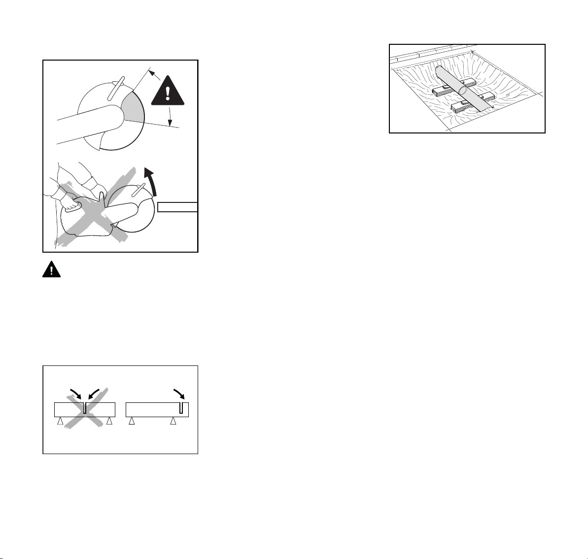
WARNING
It is essential to determine the exact
direction of the cut before applying the
abrasive wheel to the work. Wheels are
002BA550 AM
constructed for radial pressure only.
Lateral pressure must be avoided. Hold
the cut-off machine steady. To reduce
the risk of serious or fatal injury, do not
change the direction of the cut during the
cut as this may produce a high torsional
load on the abrasive wheel and may
cause it to bind, break or shatter. A
binding of the wheel can also result in
reactive forces. See section on
"Reactive Forces."
WARNING
Do not use abrasive wheels for rough
grinding. Large bending stresses occur
during such work, which may cause
abrasive wheels to shatter or break and
result in serious or fatal injury.
WARNING
To reduce the risk of injury from
shattered abrasive wheels:
1. Do not exceed the maximum
operating speed marked on the
wheel.
2. Do not use a wheel that has been
dropped.
3. Test each new wheel immediately
after installation for approximately
one minute at maximum speed
without cutting, making sure to keep
bystanders away.
4. Do not cut any material for which the
abrasive wheel is not authorized.
5. Do not grind on the side of the
abrasive wheel.
6. Do not twist, thrust, knock or drop
the machine. This can cause
damage to the wheel.
To achieve a clean and efficient cut, pull
the abrasive wheel across the work or
move it "to and fro" in the cutting
direction. Do not use force to push the
abrasive wheel into the work.
Insert the wheel into the material only as
deep as necessary to make the cut. To
reduce the amount of dust created, do
not cut all the way through stone and
concrete materials – leave a thin piece
uncut. For most such materials, this
piece can be easily broken afterwards.
Do not cock, jam or wedge the wheel in
the cut.
Always stop the engine and be sure the
wheel has stopped rotating before
setting down the cut-off machine.
If a cut-off machine cart is used, sweep
debris from the path of the wheels, as
debris under one of the cart’s wheels
may cause flexing of the abrasive wheel.
This could result in high frictional forces
and thus greatly reduce the engine
TS 410, TS 420
11
Page 14
English
002BA553 AM
power available for the actual cutting
work. It could also damage the abrasive
wheel.
STIHL recommends the use of the cart
for longer cuts in a straight line.
Wet Cutting with Abrasive Wheels
Before wet cutting, make sure water will
not damage the floor or building.
WARNING
To reduce the risk of electrocution to you
or bystanders, do not allow water or
sludge to contact live electric wires.
WARNING
To reduce the risk of injury from wheel
breakage when wet cutting with any
composite wheel:
1. Make certain water does not flow on
a wheel that is not running, since the
wheel will absorb water, which will
affect wheel balance.
2. Be certain water is applied to both
sides of wheel, since uneven
distribution can cause "one sided"
wear.
3. After finishing work, run the cutting
wheel at normal operating speed for
about 3 to 6 seconds without water
so that the remaining water is flung
off.
WARNING
To reduce the risk of injury from wheel
breakage when wet cutting with a
composite wheel that is not specifically
designed for wet cutting, never store and
reuse such a wheel that has been used
with water. Use these wheels up the
same day.
Reactive Forces including Kickback
WARNING
Reactive forces may
occur at any time the cut
ting wheel on a cut-off
machine is rotating.
The powerful force used to cut through a
workpiece can be reversed and work
against the operator. If the wheel is
slowed or stopped by frictional contact
with any solid object or by a pinch or
binding, reactive forces can occur
instantly and may result in the operator
losing control of the cut-off machine,
which, in turn, may result in serious or
fatal injury.
An understanding of the causes of these
reactive forces may help you avoid loss
of control. Reactive forces are exerted in
a direction opposite to the direction in
which the wheel is moving at the point of
contact or of pinching/binding. If the
wheel is slowed solely by frictional
contact with a solid object, such as the
workpiece, the resulting reactive forces
are normally moderate and readily
controllable by an operator who is
holding the machine properly. If,
however, the wheel is abruptly slowed or
stopped by a pinch or severe bind, the
reactive forces may be substantially
greater. The greater the force
generated, the more difficult it will be for
the operator to control the cut-off
machine. Loss of control can result in
severe personal injury or death.
Pull-away, Climbing, Pinching and
Rotational Kickback Forces
-
The most common reactive forces are
pull-away and climbing. If the contact is
at the bottom of the wheel, a cut-off
machine will try to pull away from the
operator (pull-away.) If the contact is at
the front of the wheel, the wheel may
attempt to climb the object being cut
(climbing.)
Pinching occurs when the piece being
cut closes on the wheel. A severe
binding may also occur if the wheel is
substantially sideloaded in the kerf or if
an improper or damaged diamond wheel
begins or ceases to wobble in the kerf. If
the wheel is severely pinched or bound
in the upper quadrant, the wheel may be
instantly thrown up and back towards
the operator with great force in a
rotational kickback motion. Such
kickback situations can and should
always be avoided. Pinching of the
wheel can be prevented by proper
support of the workpiece. (See below.)
Severe binding of the wheel can be
prevented by proper cutting techniques,
e.g., not sideloading the wheel, and by
the use of properly designed,
manufactured and maintained wheels.
12
TS 410, TS 420
Page 15
English
002BA146 KN
002BA603 KN
Reducing the Risk of Kickback Injury
WARNING
To reduce the risk of kickback injury,
avoid cutting with the upper quadrant of
the wheel where possible. Be especially
cautious for a pinching or binding of the
wheel in this area, which can cause
severe reactive forces in a rotational
kickback motion.
Avoid wedge action. The severed part
must not bind the abrasive wheel.
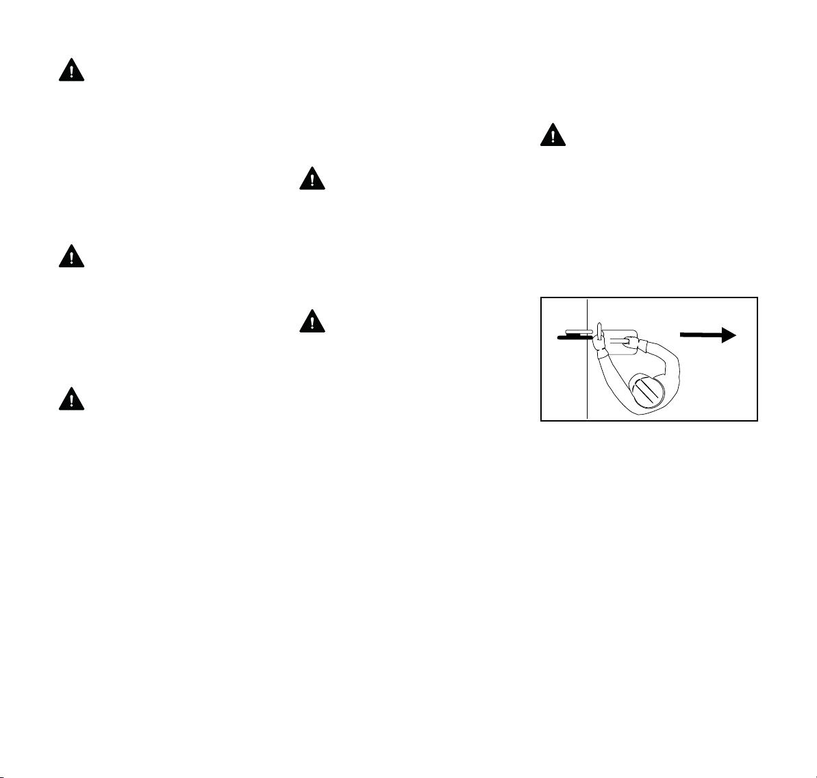
Be alert to potential movement of the
workpiece or anything else that could
cause the cut to close and pinch the
wheel. In order to reduce the risk of
pinching, support the workpiece in such
a way that the cut remains open during
the cutting process and when the cut is
finished (see illustration). Never make a
cut that results in a binding of the wheel.
If you cannot properly support the
workpiece, do not use a cutting-off
machine to make the cut; select another
tool or cutting technique that is not
subject to kickback.
Where there is a possibility of a pinch,
you can leave an uncut part that
prevents the kerf from closing and
pinching the wheel, which can later be
broken manually. If you are making a
002BA582 ST
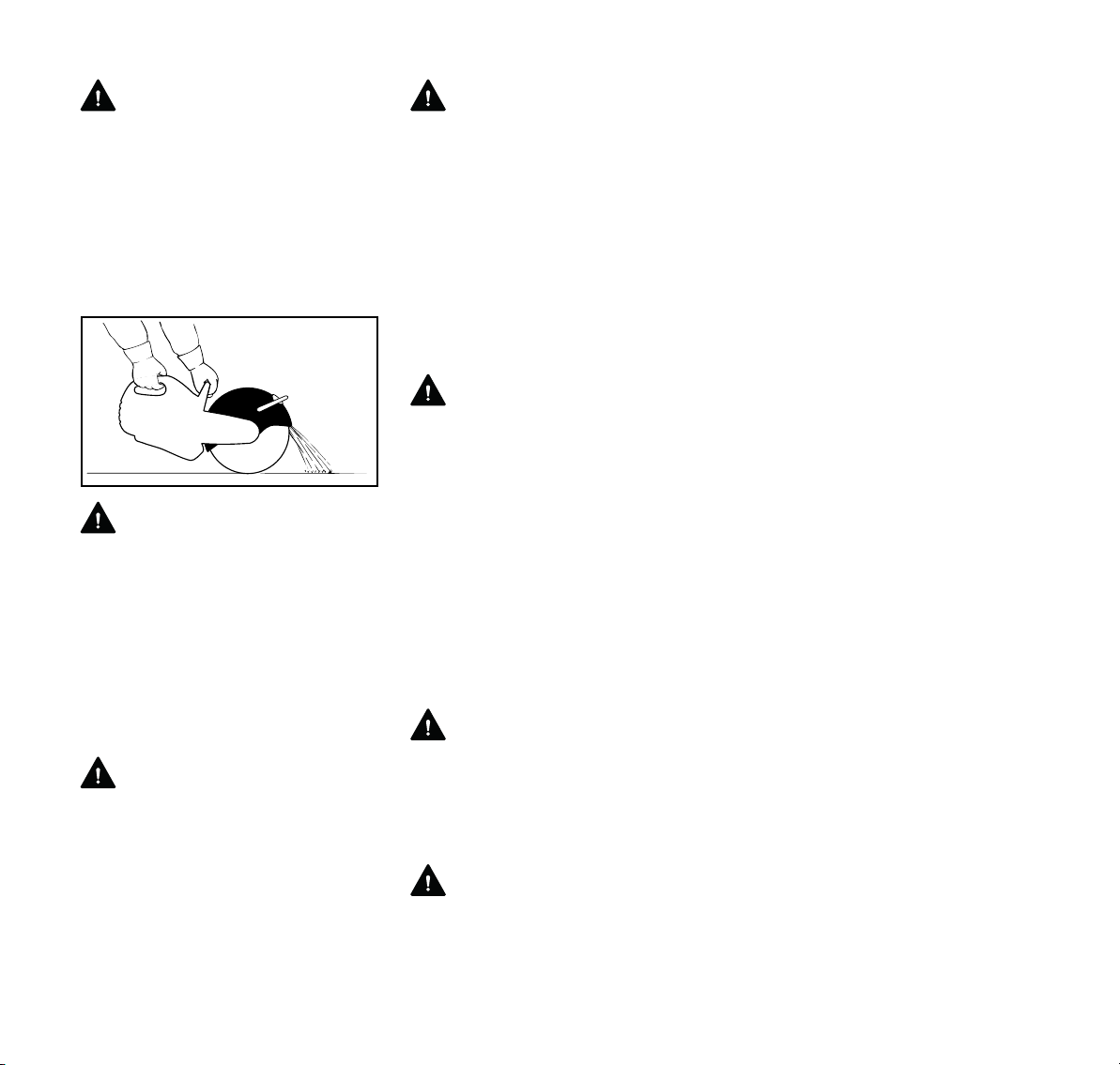
complete cut, make sure that the final,
separating cut is made at the top of the
workpiece with the bottom of the wheel.
In this way, if there is any residual
pinching, it will be at the bottom of the
wheel, where it may result in pull-away,
but not in kickback. Be alert for pullaway.
Objects to be cut must therefore be
properly supported and must be secured
against rolling away, slipping or
vibrations.
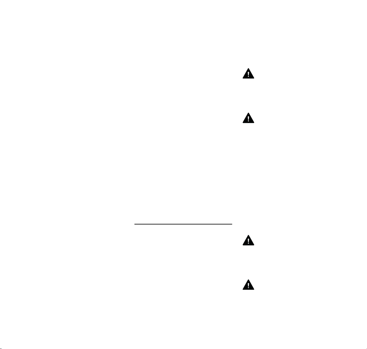
Support an exposed pipe in a trench so
that it is stable and capable of bearing
weight. If the ends of the pipe are firmly
in the ground, the ground may act as a
support where the pipe emerges into the
open. Additional support will be needed
closer to the cut, however, to prevent
sagging (see illustration). Be alert for
pipe that is under stress that may cause
it to shift when cut; pipe in the ground
may be under stress because of uneven
surfaces.
Make sure any section of pipe to be
removed is also properly supported and
will not shift. After the first cut, you may
need to move the supports or add
additional support for the second cut so
that both sides of that cut are fully
supported, including the section to be
removed. That section can also be
supported by means of a strap from
above, e.g., suspended from a backhoe.
It must be evenly supported and
properly tensioned, however, so that the
section remains in its position and does
not tend to go up or down as a whole or
on one side when separated.
Always pay attention in
subgrade/subsurface work areas –
supporting material can crumble or slide
away.
TS 410, TS 420
13
Page 16
English
WARNING
Be particularly alert when cutting a
workpiece such as a pipe with a belled
end or cutting out a section of pipe in a
trench that, if not properly supported,
can sag or drop upon completion of the
cut, creating a pinch not where you are
actually cutting but, rather, at or near the
top of the workpiece. If the pinch is in the
upper quadrant of the abrasive wheel,
kickback can result.
WARNING
Use wet-cutting whenever feasible,
since the water can act as a lubricant in
a pinch situation and thus reduce the
likelihood of reactive forces occurring
and the energy of any such forces that
do occur, making it easier to maintain
control of the machine.
WARNING
Only STIHL branded cutting
attachments are recommended. Use of
certain non-STIHL branded wheels may
be extremely dangerous. Many
substandard diamond wheels, for
instance, are available in the market. If
they are not manufactured with the
proper quality steel in their core, if they
are not properly tensioned, or if other
design or manufacturing defects exist,
they may, e.g., begin to wobble during
use, lose segments or exhibit other
operational problems that can
substantially increase the risk of
personal injury or death. If a diamond
wheel begins or ceases to wobble within
the kerf, the change in the behavior of
the wheel may cause a severe binding
that can lead to loss of control and/or
kickback. If the wheel you are using
begins to wobble or has ever wobbled,
discard it immediately. Although such a
wheel may temporarily cease to wobble,
e.g., if run without load, it will always be
prone to wobble again under certain
conditions.
WARNING
Some other non-STIHL branded
diamond wheels are manufactured with
abrasive material on their sides. Do not
use such wheels, since the abrasive
material may lead to substantially
increased reactive forces in a pinch or
sideloading situation.
WARNING
Never use chipped abrasive wheels or
circular saw blades, carbide-tipped
blades, rescue blades or wood-cutting or
toothed blades of any nature on a cut-off
machine. The use of such wheels or
blades will greatly increase the risk of
loss of control and severe personal
injury or death from reactive forces,
since the chipped section of an abrasive
wheel or the teeth of a saw blade may
catch in the material being cut and
generate substantially greater reactive
forces, including rotational kickback.
Cut-off machines are designed for use
with abrasive wheels in good condition
only. Machines designed for use with
wood-cutting or other toothed blades
use different types of guarding systems
that provide the protection necessary for
those types of blades. Machines, such
as a cut-off machine, that are designed
for use with abrasive wheels require a
different guarding system, which is not
designed to provide protection against
all dangers presented by circular saw
blades, carbide-tipped blades, rescue
blades or wood-cutting or toothed
blades of any nature.
WARNING
To reduce the risk of injury from loss of
control from reactive forces, including
kickback:
1. Hold the cut-off machine firmly with
both hands.
2. Maintain good balance and footing
at all times. Never cut while
standing on a ladder.
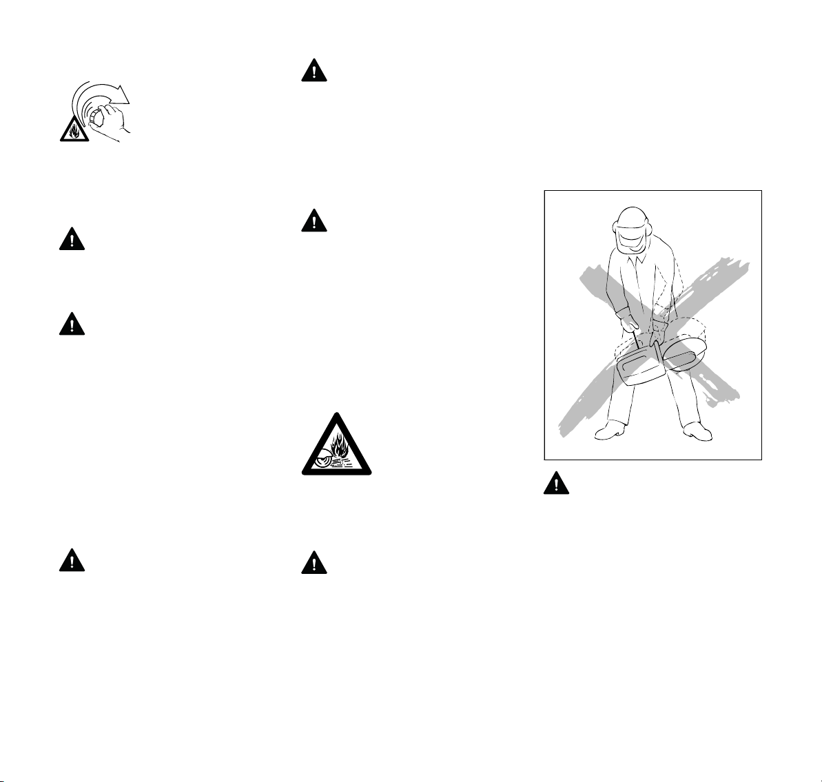
002BA554 AM
3. Position the cut-off machine in such
a way that your body is clear of the
cutting attachment. Avoid standing
in direct line with the wheel (See
illustration.) Never bend over the
cutting attachment, especially when
the guard is pulled back towards the
top and there is a risk of reactive
forces. Ensure sufficient freedom of
movement, especially in trenches.
Make sure there is sufficient space
for the user and the fall of the
severed part.
4. Do not cut above shoulder height.
14
TS 410, TS 420
Page 17
English
5. Only STIHL branded diamond and
composite abrasive wheels are
recommended. The use of nonSTIHL branded wheels can be
extremely dangerous. Never work
with a diamond wheel that wobbles
or that has ever wobbled or that is
manufactured with abrasive
material on its sides.
6. Do not cut wood or any other
material for which the abrasive
wheel is not authorized.
7. Never use circular saw blades,
carbide-tipped blades, rescue
blades, wood-cutting blades or
toothed blades of any nature. Their
use increases the risk of injury from
blade contact, thrown tips and
reactive forces, including kickback.
8. Begin cutting and continue at full
throttle.
9. Do not overreach.
10. Never sideload a wheel in the kerf.
11. Use your cut-off machine for cutting
only. It is not designed for prying or
shoveling away any objects.
12. Be especially alert for reactive
forces, including kickback, when
cutting with the front and upper
quadrant of the wheel. Never pull
the top of the wheel guard back
beyond the limit stop.
13. Be alert to shifting of the workpiece
or anything that could cause the cut
to close and pinch the wheel,
especially in the upper quadrant.
Support the workpiece in such a
way that the cut remains open.
Never make a cut that results in a
binding of the wheel.
14. Use wet-cutting whenever feasible.
In a pinch situation the water can act
as a lubricant and reduce the
energy of reactive forces.
15. Release the pressure on the cut-off
machine as you reach the end of the
cut. Too much pressure may cause
the operator to lose control of the
cut-off machine when the abrasive
wheel completes the cut. The
abrasive wheel may contact the
operator or strike some foreign
object and shatter.
16. Use extreme caution when
reentering a cut and do not turn the
wheel at an angle or push the wheel
into the cut as this may result in a
binding of the wheel.
Gyroscopic Forces
Be alert for gyroscopic forces that are
caused by the rapid spinning of the cutoff wheel. These forces result in
opposition to directional change, e.g.,
when the operator attempts to move the
machine in a sideways direction.
Maintenance, Repair and Storing of the
Cut-Off Machine
Maintenance, replacement, or repair of
the emission control devices and
systems may be performed by any
nonroad engine repair establishment or
individual. However, if you make a
warranty claim for a component that has
not been serviced or maintained
properly or if nonapproved replacement
parts were used, STIHL may deny
warranty coverage.
Never operate a cut-off machine that is
damaged, improperly adjusted or not
completely or securely assembled.
Follow the maintenance and repair
instructions in the appropriate sections
of your instruction manual.
WARNING
Use only STIHL replacement parts for
maintenance and repair. Use of parts
manufactured by others may cause
serious or fatal injury.
WARNING
Always stop the machine and make sure
that the wheel is stopped before doing
any maintenance or repair work or
cleaning the cut-off machine. Do not
attempt any maintenance or repair work
not described in your instruction manual.
Have such work performed only at your
STIHL servicing dealer.
Clean off grinding dust after finishing
work. Tighten all nuts, bolts and screws
except the carburetor adjustment
screws after each use.
Do not clean your machine with a
pressure washer. The solid jet of water
may damage parts of the machine.
WARNING
Never test the ignition system with spark
plug boot removed from spark plug or
with an unseated spark plug, since
uncontained sparking may cause a fire.
WARNING
To reduce the risk of fire and burn injury,
use only spark plugs authorized by
STIHL. Always press spark plug boot
TS 410, TS 420
15
Page 18

English
snugly onto spark plug terminal of the
proper size. (Note: If terminal has a
detachable SAE adapter nut, it must be
attached.) A loose connection between
spark plug terminal and ignition wire
connector in the boot may create arcing
that could ignite combustible fumes and
cause a fire. Keep spark plug clean, and
make sure ignition lead is in good
condition.
WARNING
Do not operate your cut-off machine if
the muffler is damaged, missing or
modified. An improperly maintained
muffler will increase the risk of fire and
hearing loss. Never touch a hot muffler
or spill fuel or other flammable liquid
over it. Burn injuries or fire will result. If
your muffler was equipped with a sparkarresting screen to reduce the risk of fire
(e. g. in the USA, Canada and
Australia), never operate your cut-off
machine if the screen is missing or
damaged.
In California, it is a violation of § 4442 or
§ 4443 of the Public Resources Code to
use or operate gasoline-powered tools
on forest-covered, brush-covered or
grass-covered land unless the engine’s
exhaust system is equipped with a
complying spark arrester that is
maintained in effective working order.
The owner/operator of this product is
responsible for properly maintaining the
spark arrester. Other states or
governmental entities/agencies, such as
the U.S. Forest Service, may have
similar requirements. Contact your local
fire agency or forest service for the laws
or regulations relating to fire protection
requirements.
For any maintenance please refer to the
maintenance chart and to the warranty
statement near the end of the instruction
manual.
Store wheels on a flat surface in a dry
place, preferably at a constant
temperature, where there is not a risk of
frost. Do not store a cut-off machine with
a wheel mounted on the machine. Store
cut-off machine in a high or locked
place, away from children.
Empty the fuel tank before storing for
longer than a few days. Store fuel only in
correctly labeled and approved
containers. Avoid direct skin contact and
do not inhale the gas vapors.
Sample applications
Water connection
– A water attachment kit is mounted
on the machine for use with all types
of water supply.
– A pressurized 2.6 gallons (10 liter)
water tank is available from STIHL
for wet cutting.
– A water tank for mounting on the
Cutquik cart is also available for wet
cutting.
Most diamond cutting wheels are
suitable for wet cutting
Wet cut whenever feasible. It increases
the service life and cutting speed of
diamond cutting wheels.
Ensure that the cutting wheel is
generously supplied with water.
Wet cutting helps to suppress dust.
The water binds the dust.
The cutting wheel must be supplied with
at least 20 fl. oz (0.6 liters) water per
minute.
Wet cutting can reduce the energy of
reactive forces. In a pinch situation, the
water can act as a lubricant.
16
TS 410, TS 420
Page 19
English
Composite resin wheels can be used for
dry cutting of metals or for wet or dry
cutting of concrete, stone or masonry.
Composite resin wheels designed for
dry cutting
Special procedures must be followed
when wet cutting with a composite nondiamond wheel designed for dry cutting.
See the section entitled "Wet Cutting
with Abrasive Wheels" in the safety
precautions of this manual. Wet cutting
is generally not suitable for cutting
metals.
Composite resin wheels designed for
wet cutting
Adjust water flow rate
during cutting so it is suf
ficient to bind all the dust
that occurs (at least
20 fl. oz (0.6 L/min)).
If the water flow rate is too high, the
cutting wheel may skim on the water
surface in the cut and greatly reduce
cutting performance. To avoid this, do
not exceed a water flow rate of about
135fl.oz (4L/min).
Use water properly:
1. Be certain water is applied to both
sides of wheel, since uneven
distribution can cause one sided
wear with possible wheel breakage.
2. Make certain water does not flow on
wheel that is not running, since the
wheel will absorb water and that will
affect wheel balance.
3. After finishing work, run the cutting
wheel at normal operating speed for
about 3 to 6 seconds without water
so that the remaining water is flung
off.
Respiratory protection
-
WARNING
When wet cutting at the recommended
flow rate is not utilized, the operator and
any bystanders should always wear a
respirator approved by NIOSH/MSHA
for the material being cut. Even if wet
cutting, an operator who is actively
cutting for more than two hours a day
should wear at least a NIOSH-approved
disposable respirator.
The cutting sequence
The cutting sequence is important when
cutting openings and recesses, etc. The
last cut must always be made in such a
way that the cutting wheel cannot
become bound and so that the user is
not at risk of being injured by the part
that has been cut off or out.
If applicable, leave small ridges of uncut
material to hold the severed part in
position. These ridges can subsequently
be broken through.
A number of points must be decided
before the part is finally severed:
– How heavy is the part?
– In which direction can it move after
being severed?
– Is it under tension?
Helpers must not be put at risk of injury
when the part is broken off or out.
Cutting in several passes
TS 410, TS 420
Points to be noted with diamond and
composite cutting wheels
Object to be cut
– Must be fully supported
– Must be secured so that it cannot
roll or slip away
– Must be protected against vibration
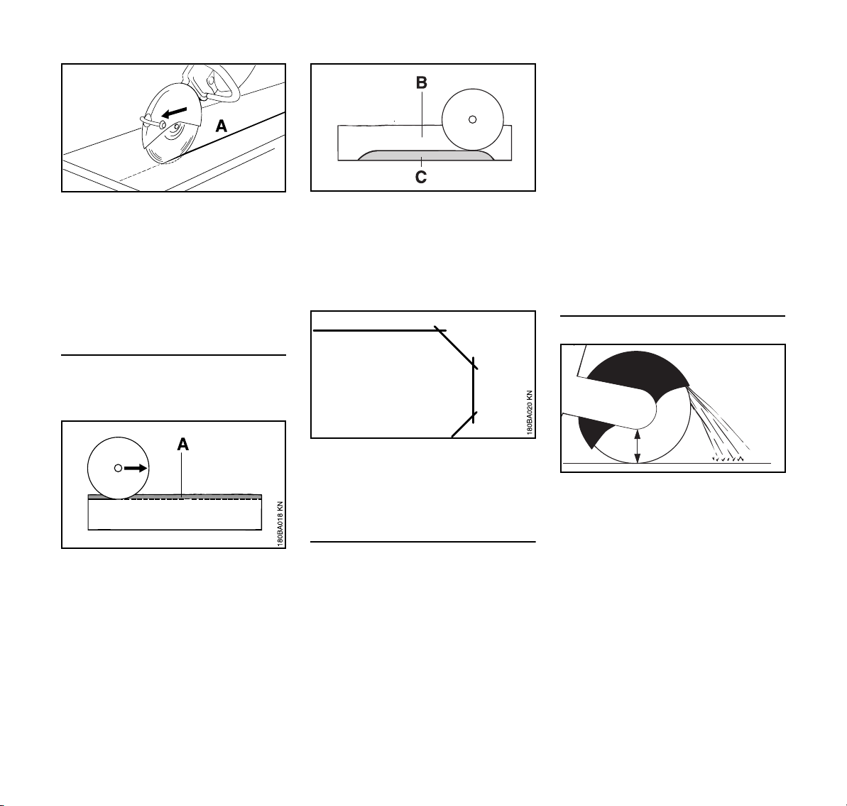
N Mark cutting line (A).
17
Page 20
English
N Work along the cutting line. If
corrections are necessary, always
reposition the cutting wheel, taking
care to ensure that it is not wedged.
The cutting depth per pass should
not exceed 5 to 6 cm (2“ to 2 1/2“).
Thicker material must be cut in
several passes.
Cutting slabs
N Secure the slab (e. g. on a non-slip
surface, sandbed).
180BA027 AM
N Cut deeper into the parting cut (B).
N Leave a ridge (C) of uncut material.
N Cut through the slab at the ends so
the material does not chip.
N Then break the slab.
N Determine sequence of severing
cuts.
N Grind a guide groove along the line
marked.
N Make cuts deeper along the guide
groove – observe recommended
cutting depth on each pass. For
180BA028 AM
small corrections of direction, do not
tilt the abrasive wheel, but always
position it anew instead. If
necessary, leave small ridges that
hold the part that is to be separated
in position. Break these ridges
manually after the last cut.
Cutting concrete pipe
N Cut a guiding groove (A) along the
marked line.
18
N Curves must be cut in several
straight passes, taking care to
ensure that the cutting wheel does
not become wedged.
Cutting pipes, round and hollow bodies
N Secure pipes, round and hollow
bodies against vibrations, slipping
and rolling away.
N Note direction of fall and weight of
the severed part.
N Determine and mark the cutting line;
avoid metal reinforcement to the
extent possible, especially in the
direction of the severing cut.
A
002BA557 AM
The procedure is dependent on the
outer diameter of the pipe and the
maximum possible cutting depth of the
abrasive wheel (A).
N Secure pipe against vibrations,
slipping and rolling away.
N Note weight, tension and direction
of fall of the part to be severed.
TS 410, TS 420
Page 21
English
002BA559 AM
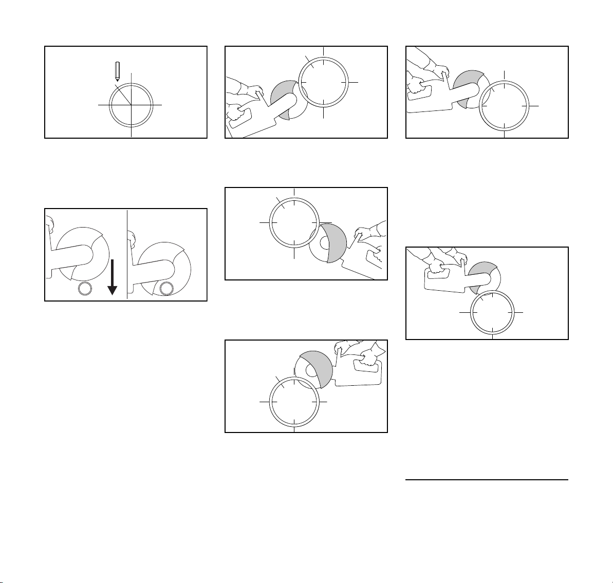
N Determine and mark direction of cut.
N Determine sequence of cuts.
Outer diameter of pipe is smaller than
the maximum cutting depth
N Make one cut from the top to the
bottom
Outer diameter of pipe is greater than
the maximum cutting depth
Plan first, then cut. Several cuts are
needed – correct sequence is important.
N Turn guard to rear stop.
002BA528 AM
N Always start at the bottom, use the
front and upper part of the abrasive
wheel for cutting.
N Use the front and upper part of the
002BA558 AM
abrasive wheel for cutting the
opposite lower side. Make sure that
the cut at the bottom is complete.
N Next, make a first lateral cut on the
top half of the pipe, connecting with
the kerf from the bottom half.
002BA560 AM002BA561 AM002BA562 AM
N A second lateral cut is then made in
the marked area. To keep the pipe
from pinching during this cut, never
cut into the area of the final cut.
Only make the final top cut once all
bottom and lateral cuts have been
completed and connect with one
another.
N Always make the final separating
cut from the top (approx. 15 % of the
pipe circumference). If the
workpiece is properly supported, it
should not pinch when the cut is
completed. If there is any residual
pinching, however, it will be at the
bottom of the wheel, where it may
result in pull-away, but not in
kickback. Be alert for pull-away.
Concrete pipe – cut recess
002BA563 AM
TS 410, TS 420
Sequence of cuts (1 to 4) is important:
N First, cut hard-to-reach areas.
19
Page 22

English
180BA025 AM
1
2
N Always make severing cuts so that
the abrasive wheel is not pinched.
N Use wedges and/or leave ridges
that are broken after cutting.
4
3
N If the severed part remains in the
recess after cutting (due to wedges,
ridges used), do not make any
further cuts – break the severed
part.
Cutting wheels Composite resin cutting
wheels
Cutting wheels are exposed to
extremely high loads especially during
hand-held cutting.
Only use abrasive whhels that comply
with ANSI B 7.1 for hand-held machines
180BA024 AM
and are correspondingly labeled. Note
that the maximum permissible speed of
the cutting wheel must be higher than
the maximum spindle speed listed on
the wheel guard label.
The cutting wheels that have been
developed for STIHL by well-known
manufacturers of abrasive wheels are of
high quality and tailored precisely to the
respective intended use as well as the
engine performance of the cut-off
machine.
Transport and storage
– Do not expose cutting wheels to
direct sunshine or other thermal
stresses during transport and
storage.
– Avoid jolting and impacts.
– Stack cutting wheels flat on a level
180BA026 AM
surface in the original packaging in
a dry place where the temperature
is as constant as possible.
– Do not store cutting wheels in the
vicinity of aggressive fluids.
– Store cutting wheels in a frost-free
place.
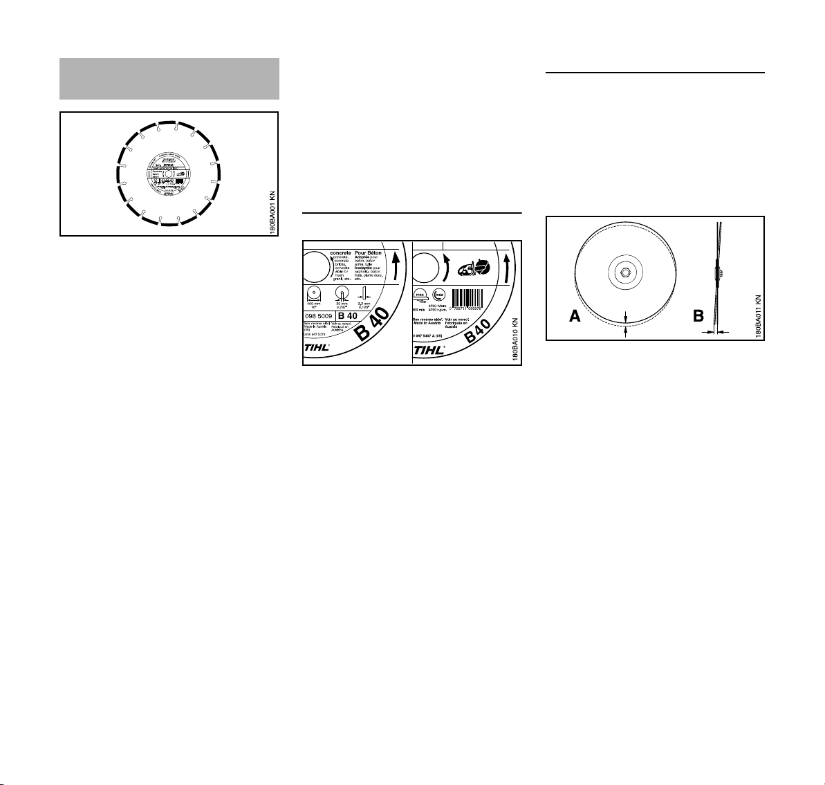
Types:
– for dry applications
– for wet applications
Economic benefit is improved and
premature wear can be avoided by
choosing and using the correct
composite resin cutting wheel. The short
name (e.g. “asphalt“, “concrete“)
– on the label and
– on the packaging (table with
recommended uses)
can help to ensure the correct choice.
STIHL composite resin cutting wheels
are suitable, depending on the version,
for cutting the following materials:
– Asphalt
– Concrete
– Stone
– Ductile cast pipes
– Steel; STIHL composite resin
cutting wheels cannot be used to cut
railway tracks.
Do not cut any other materials – risk of
accident!
20
TS 410, TS 420
Page 23
English
Diamond cutting wheels
For wet applications.
Economic benefit is improved and
premature wear can be avoided by
choosing and using the correct diamond
cutting wheel. The short name (see
following explanation)
– on the label and
– on the packaging (table with
recommended uses)
can help to ensure the correct choice.
STIHL diamond cutting wheels are
suitable, depending on the version, for
cutting the following materials:
– Asphalt
– Concrete
– Stone (hard rock)
– Abrasive concrete
– Green concrete
– Clay bricks
– Clay pipes
– Ductile iron
– Structural steel up to 10 mm thick
Do not cut any other materials. Cut-off
machines are not suitable for cutting
certain metals and other substances.
Never use diamond abrasive wheels
with abrasive material on their sides,
since in a pinch situation, they can result
in extreme kickback – Risk of severe or
fatal injury.
Short names
The short name is a combination of
letters and numerals with up to four
digits:
– The letters indicate the main area of
use for the cutting wheel.
– The numerals indicate the
performance class of the STIHL
diamond cutting wheel.
Letter Main area of use
A Asphalt
B Concrete
BA Concrete, Asphalt
S Stone (rock)
SB* Rock, Concrete
*)
can be used for structural steel up
to 10 mm thick and ductile iron – not
suitable for continuous cutting of
such materials
Radial and axial run-out
A correctly mounted spindle bearing on
the cut-off machine is essential for a
long service life and efficient operation
of the diamond cutting wheel.
Using a cutting wheel on a cut-off
machine with defective spindle bearing
can lead to axial and radial run-out.
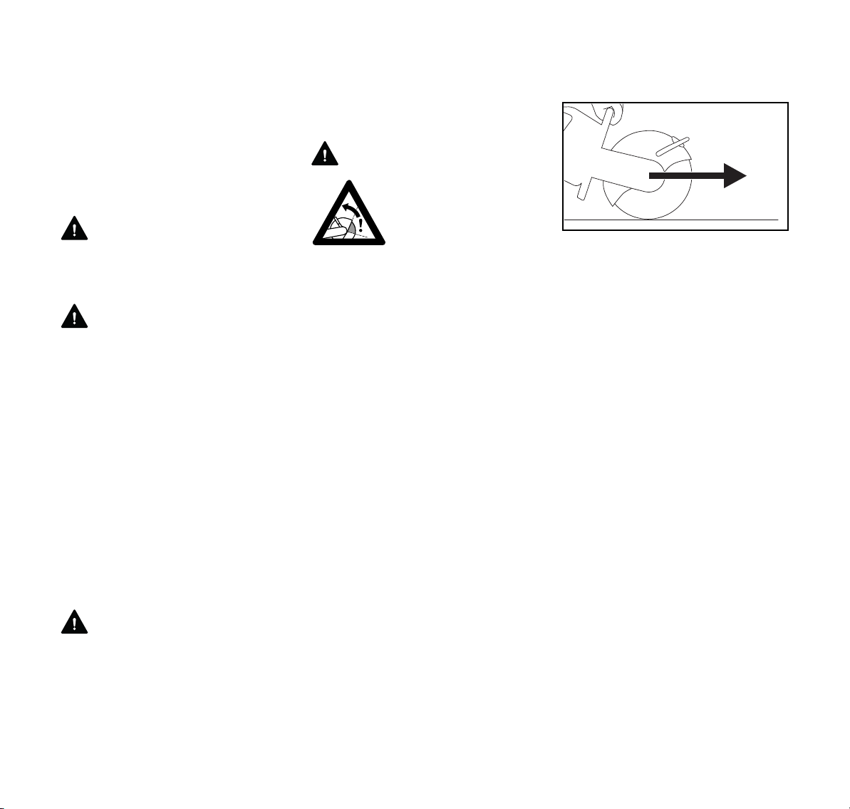
Excessive radial run-out (A) causes
individual diamond segments to be
overloaded and to overheat. This can in
turn lead to stress cracking in the wheel
core or to softening of individual
segments.
Axial run-out or spindle wobble (B)
results in higher thermal stress and
wider cuts.
TS 410, TS 420
21
Page 24

English
Troubleshooting
Cutting wheel
Problem Cause Remedy
Frayed edges or tears, cut wanders out
Radial or axial run-out Consult a dealer
of line, increased wear at the sides of the
segments
Cutting wheel wobbles Use a new cutting wheel
Frayed edges, cut wanders out of line, lit
tle or no cutting performance, sparking
-
Cutting wheel is blunt; built-up edges on cut
ting wheels for stone
-
Dress the cutting wheel for stone by
briefly cutting in abrasive material; use a
new cutting wheel for cutting asphalt
Poor cutting performance, high level of
segment wear
Chipping or cracking in the wheel core
and segments
Undercutting Cutting in a material for which the wheel is
1)
STIHL recommends that a STIHL servicing dealer be consulted.
Cutting wheel rotates in the wrong direction Mount the cutting wheel with correct
direction of rotation
Overload Replace immediately with a new cutting
wheel
Use a new cutting wheel; note the differ
not rated
ent cutting layers in different materials
1)
-
22
TS 410, TS 420
Page 25
English
Undercut
Undercutting is a wearing away of the
steel core at or just below the diamond
segments. When cutting road surfaces,
do not cut through into the more
abrasive ballast (gravel, crushed rock)
below, as indicated by a light colored
dust. This can cause excessive
undercutting, resulting in wheel
breakage and/or thrown segments.
WARNING
Immediately replace a diamond wheel if
the core has been severely undercut.
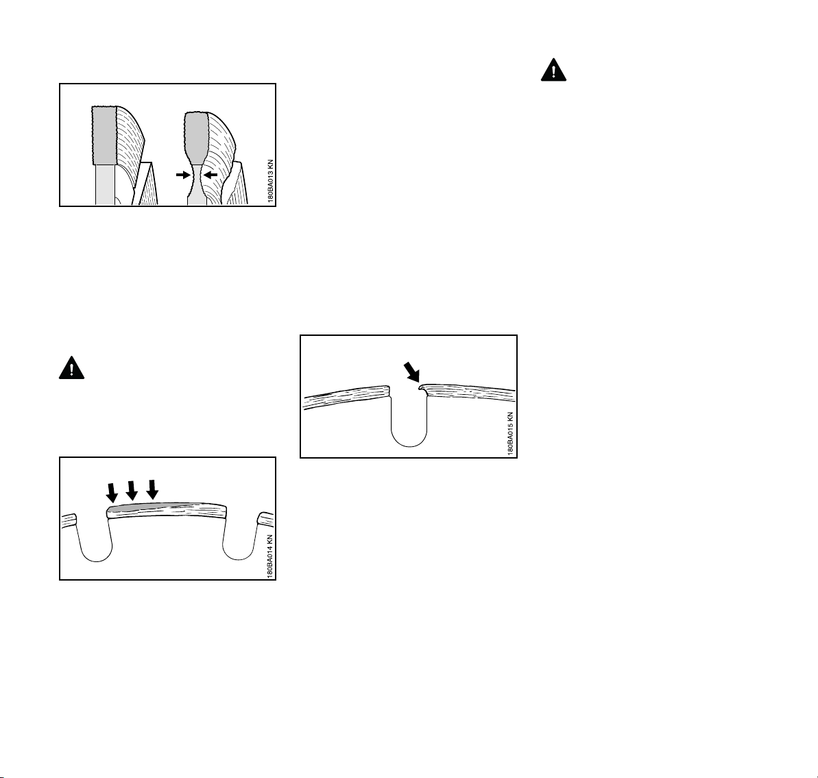
Built-up edges, dressing
Built-up edges can form:
– when cutting extremely hard
material, such as granite,
– as a result of incorrect handling,
such as applying excessive feed
force.
Built-up edges increase vibrations,
reduce cutting performance and cause
sparking.
Diamond cutting wheels must be
"dressed" at the first sign of built-up
edges. For this purpose, briefly cut a
more abrasive material, such as
sandstone, aerated concrete or asphalt.
Wet cutting helps to prevent the
formation of built-up edges.
WARNING
Such cutting wheels may break apart or
throw off segments during use or lead to
significant reactive forces, causing
serious or fatal injury. Replace them
immediately.
Built-up edges are identified by a pale
grey deposit on the top of the diamond
segments that clogs and blunts the
segments.
TS 410, TS 420
If you continue to use a cutting wheel
with blunt segments, the segments may
soften as a result of excessive heat built
up. The wheel core will also overheat
and lose its mechanical strength. This
can lead to considerable stress, as
clearly indicated by stress cracks and/or
a wobbling movement of the cutting
wheel.
23
Page 26
English
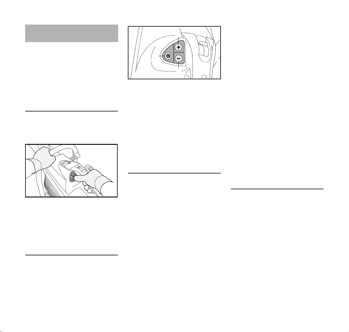
1307BA001 KN
2
1
370BA085 KN
3
Electronic water control
STIHL cut-off machines may be
equipped with an electronic water
control system.
The electronic water control makes it
possible to feed the optimum amount of
water to the cutting wheel. No water is
fed to the cutting wheel during idling or
when the machine is turned off.
Before starting work
N Familiarize yourself with the control
panel and sequence of motions
while the engine is switched off.
N All of the control panel buttons can
be reached with the thumb of the
right hand while the right hand
remains on the rear handle.
N The left hand always remains on the
handlebar.
Control Panel
When the engine is running, it is
possible to activate/deactivate the
electronic water control and adjust the
water flow.
1 Button (+):
activates the electronic water
control or increases water flow to
cutting wheel.
2 Button (–):
activates the electronic water
control or decreases water flow to
cutting wheel.
3 Deactivates electronic water
control; no water is fed to the cutting
wheel.
Using the Electronic Water Control
N Start engine: see the chapter
"Starting/Stopping the Engine."
N Briefly push the (+) button or (–)
button with the thumb of the right
hand. The right hand must always
remain on the rear handle while
doing so; the left hand must always
remain on the handlebar. No water
is fed to the cutting wheel during
idling.
During use, the set amount of water is
fed to the cutting wheel.
N Adjust water flow if necessary – to
do so, briefly push the (+) button or
(–) button with the thumb of the right
hand until the correct water quantity
is attained at one of the settings.
The right hand must always remain
on the rear handle while doing so;
the left hand must always remain on
the handlebar.
The water pressure will affect the actual
amount of water flow at any setting. It
may be necessary to use a higher
setting with a lower water pressure, e.g.,
when using a pressurized or gravity
water tank. For proper dust suppression
and cutting performance, always make
sure that the water flow is within the
proper range, as described in the
chapter "Sample Applications."
If the cut-off machine is idling after use,
no more water will be fed to the cutting
wheel – the electronic water control,
however, remains activated. With
continued use, the last setting will be
automatically re-entered.
If the engine is stopped and restarted,
the electronic water control is switched
off.
Maintenance and Care
If too little water or no water is fed to the
cutting wheel during use although the
electronic water control has been
activated:
24
TS 410, TS 420
Page 27
English
2
370BA086 KN
1
1
1
2
370BA068 KN
3
2
370BA069 KN
1
3
1
1
1
2
370BA070 KN
0
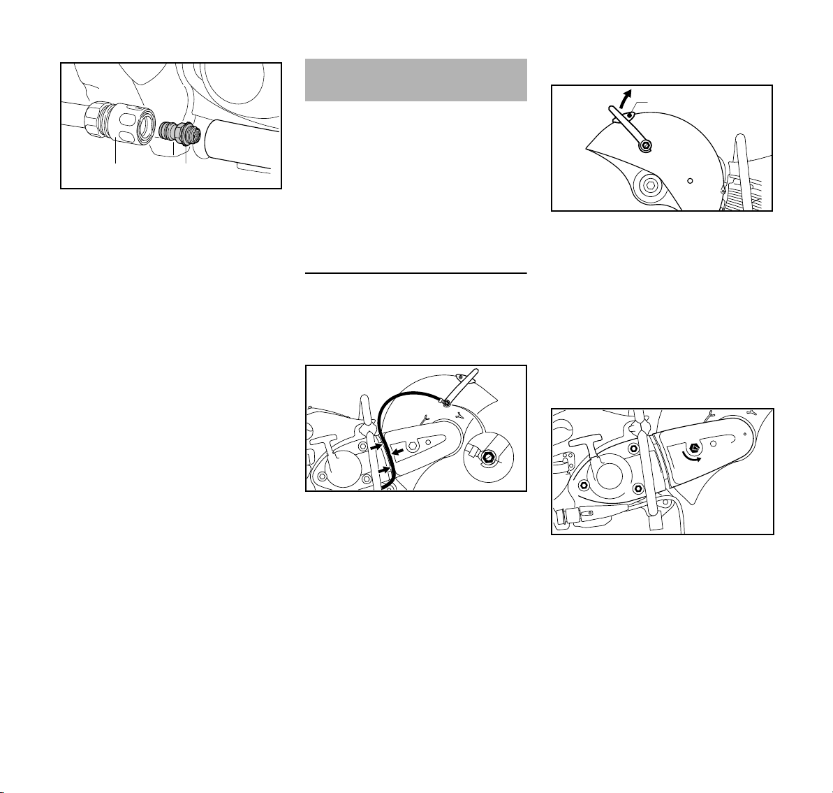
N remove the coupling sleeve (1);
N unscrew the "water connection with
screen" (2) and rinse under running
water – the screen remains on the
water connection.
Assembling the cast arm and
guard
The "cast arm with guard" is mounted on
the inboard side by the manufacturer.
The "cast arm with guard" can also be
mounted on the outboard side
depending on requirements.
Assembly on the inboard side is
recommended for freehand cutting on
account of the better balance.
Outboard mounting
N Disassemble the cutting wheel (see
“Fitting / replacing an cutting wheel”)
Remove water attachment
Removing the adjusting lever
N Unscrew the banjo bolt (1) with the
combination wrench and remove it
together with the seal – in the
process, remove the square nut
from the inside of the guard from the
guide
N Remove screw (2)
N Turn the adjusting lever (3) upwards
and remove
Slackening the V-belt
N Unscrew the banjo bolt (1) with the
combination wrench – in the
process, remove the square nut
from the inside of the guard from the
guide
N Remove the water hose (2) with
connector from the adjusting
lever (3)
N Pull the water hose (2) out of the
guide (arrows) in the V-belt guard
N Unscrew the nuts (1) – do not
remove them
N Turn the tensioning nut (2)
counterclockwise with the
combination wrench –
approx. 1/4 turn, as far as it will
go = 0
TS 410, TS 420
25
Page 28
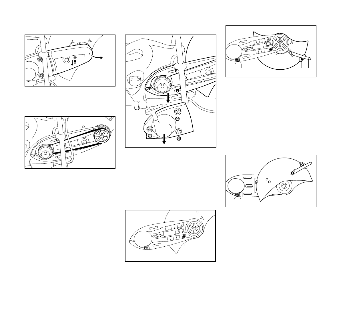
English
2
1
370BA071 KN
3
370BA079 KN
4
370BA072 KN
1
2
3
1
1
1
370BA073 KN
1
370BA074 KN
4 5
3
2
A
4
5
370BA075 KN
6
Removing the V-belt guard
N Remove screw (1)
N Raise the V-belt guard (2) slightly
and pull it off to the front
N Remove the V-belt (3) from the front
pulley (4)
Remove the "cast arm with guard"
N Turn the guard so that it is in the
position shown (see picture)
N Screw in and tighten the stop pin (1)
N Move the adjusting lever (2) to
position A
N Screw in the bolt (3) and tighten up
N Unscrew the bolt (4) of the limit
stop (5)
N Remove the limit stop (5)
N Unscrew the nuts (1)
N Remove the "starter cover with
rewind starter" (2)
N Remove the "cast arm with
guard" (3) from the studs
Preparing the "cast arm with guard" for
outboard mounting
N Turn the "cast arm with guard" so
that the guard is on the outboard
side
N Insert limit stop (5) – align the hole
in the limit stop with the hole in the
cast arm
N Unscrew stop pin (1)
26
N Screw in the bolt (4) and tighten up
TS 410, TS 420
Page 29
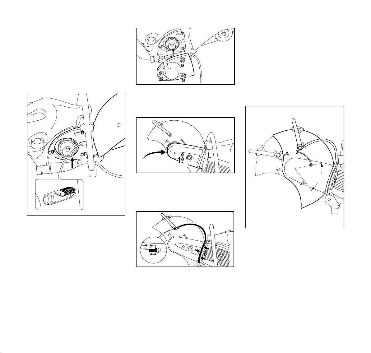
English
1
1
2
2
370BA008 KN
1
2
4
3
6
6
2
2
2
370BA051 KN
6
5
8
370BA077 KN
7
1
1
370BA078 KN
2
3
370BA076 KN
A
N Insert the square nut into the guide
in the guard and hold it in place
N Screw in the shorter banjo bolt (6)
and washer at the adjusting lever
and tighten up with the combination
wrench
Mount "cast arm with guard" – guard on
the outboard side
N Fit the "starter cover with rewind
starter" (5) over the studs (2)
N Tighten up the nuts (6) by hand
N Push the V-belt guard (7) into place
N Screw in the bolt (8) and tighten up
Connect water connection
N Fit the support with the longer banjo
bolt on the adjusting lever (3) –
screw in the banjo bolt and tighten
with the combination wrench
N Insert the water hose into the guide
in the V-belt guard (arrow) from the
shut-off cock towards the guard –
avoid tight radiuses
Checking the adjustment range of the
guard
N Press the oblong holes (1) in the
"cast arm with guard" on to the
studs (2), guiding the ribbed V-belt
over the front pulley
NOTICE
The belt action must run smoothly.
N The belt tensioner (3) must sit close
to the lug (4)
TS 410, TS 420
N Insert the longer banjo bolt (1)
through the connector (2) of the
water attachment – observe the
position of the connector
N Insert the square nut into the guide
in the guard and hold it in place
N Rotate the guard forwards and
backwards as far as possible –
adjustment range (A) must be
limited by the stop pin
Continue as described in the chapter
“Tensioning the V-belt”.
27
Page 30
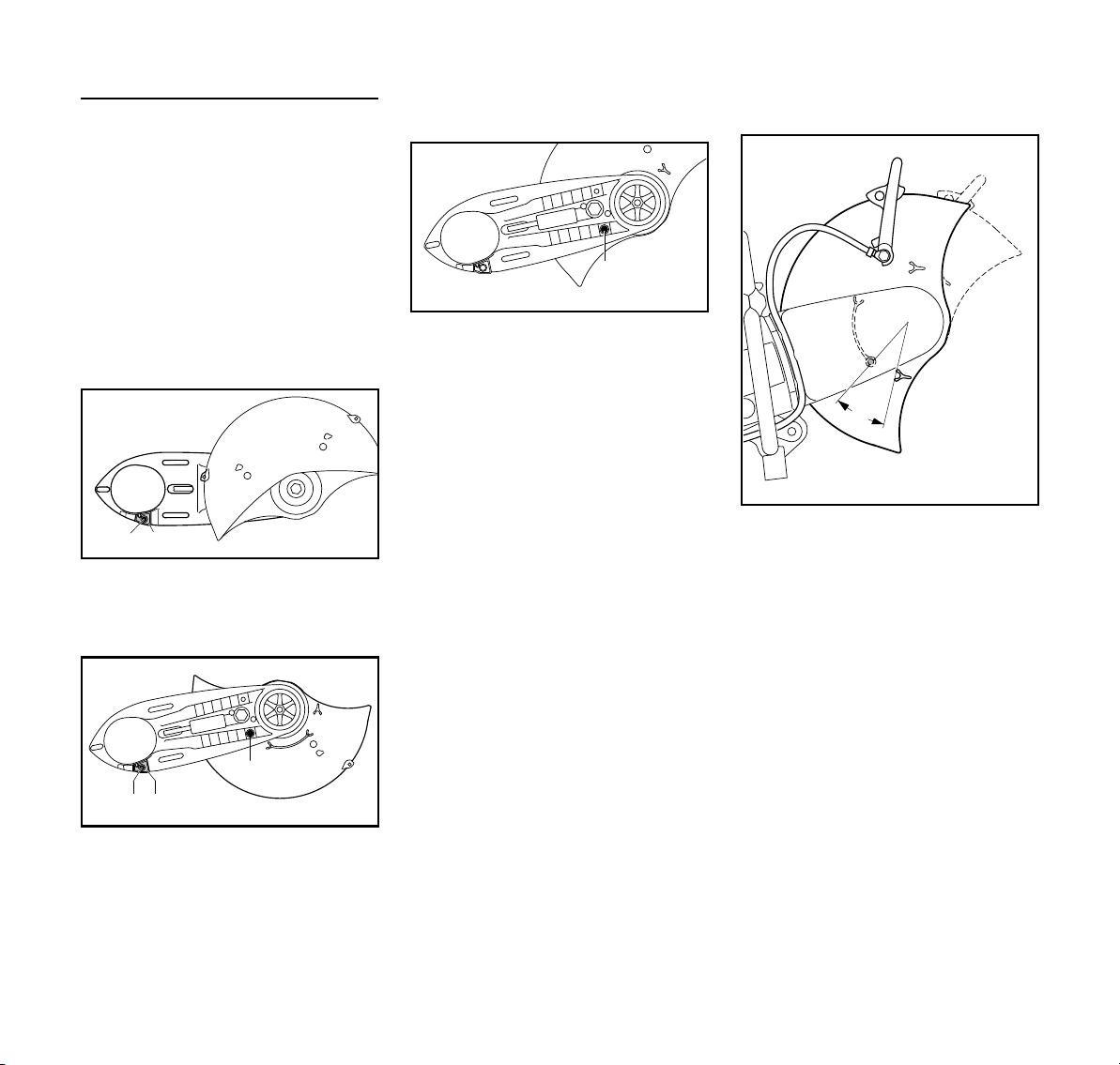
English
1
2
370BA080 KN
3
370BA081 KN
1
2
3
370BA082 KN
A
370BA083 KN
Inboard mounting
N Disassemble the cutting wheel (see
“Fitting / replacing an cutting wheel”)
N Remove water attachment
N Remove the adjusting lever
N Slacken the V-belt
N Remove the V-belt guard
N Remove the "cast arm with guard"
Preparing the "cast arm with guard" for
inboard mounting
N Unscrew the screw (1) of the limit
stop (2)
N Remove the limit stop (2)
N Screw in the bolt (1) and tighten up
N Unscrew stop pin (3)
N Turn the guard so that it is in the
position shown (see picture)
N Screw in and tighten the stop pin (3)
N Install the adjusting lever
N Mount "cast arm with guard" – guard
on the inboard side
N Install the V-belt guard
N Connect water connection
Check the adjustment range of the
guard
N Rotate the guard forwards and
backwards as far as possible –
adjustment range (A) must be
limited by the stop pin
Continue as described in the chapter
“Tensioning the V-belt”.
N Turn the "cast arm with guard" so
that the guard is on the inboard side
N Insert limit stop (2) – align the hole
in the limit stop with the hole in the
cast arm
28
TS 410, TS 420
Page 31

English
1
1
1
2
370BA037 KN
0
1
1
1
370BA012 KN
1
1
1
370BA013 KN
370BA014 KN
1
Tensioning the ribbed V-belt
This machine is equipped with an
automatic spring-action V-belt
tensioning device.
Prior to tensioning of the ribbed v-belt,
the nuts (1) must be loosened and the
arrow on the tensioning nut (2) must
point to 0.
N otherwise loosen the nuts (1) and
the tensioning nut (2) with the
combination wrench
counterclockwise –
approx. 1/4 turn, as far as
possible = 0
WARNING
The tensioning nut is spring-loaded –
hold the combination wrench securely.
N Turn the tensioning nut clockwise
approx. 1/8 turn – the tensioning nut
will be engaged by the spring
N Continue turning approx. 1/8 turn –
up to the stop
NOTICE
Do not turn the combination wrench
further by force.
The ribbed V-belt is automatically
tensioned by the force of the spring in
this position.
N Remove the combination wrench
from the tensioning nut
N Tighten up the nuts (1)
Retensioning the ribbed V-belt
Fitting / replacing an abrasive
wheel
The engine must be switched off for
fitting or replacement – set slide control
to STOP or 0.
Blocking the shaft
N Slide the locking pin (1) through the
bore in the V-belt guard
N Turn the shaft with the combination
wrench until the locking pin (1)
engages in the bore behind the
guard
N to tighten the ribbed v-belt, fit the
combination wrench over the
tensioning nut as illustrated
The V-belt is retensioned without the aid
of the tensioning nut.
N Undo the nuts (1)
The V-belt is automatically tensioned by
the force of the spring.
N Tighten up the nuts (1) again
TS 410, TS 420
29
Page 32
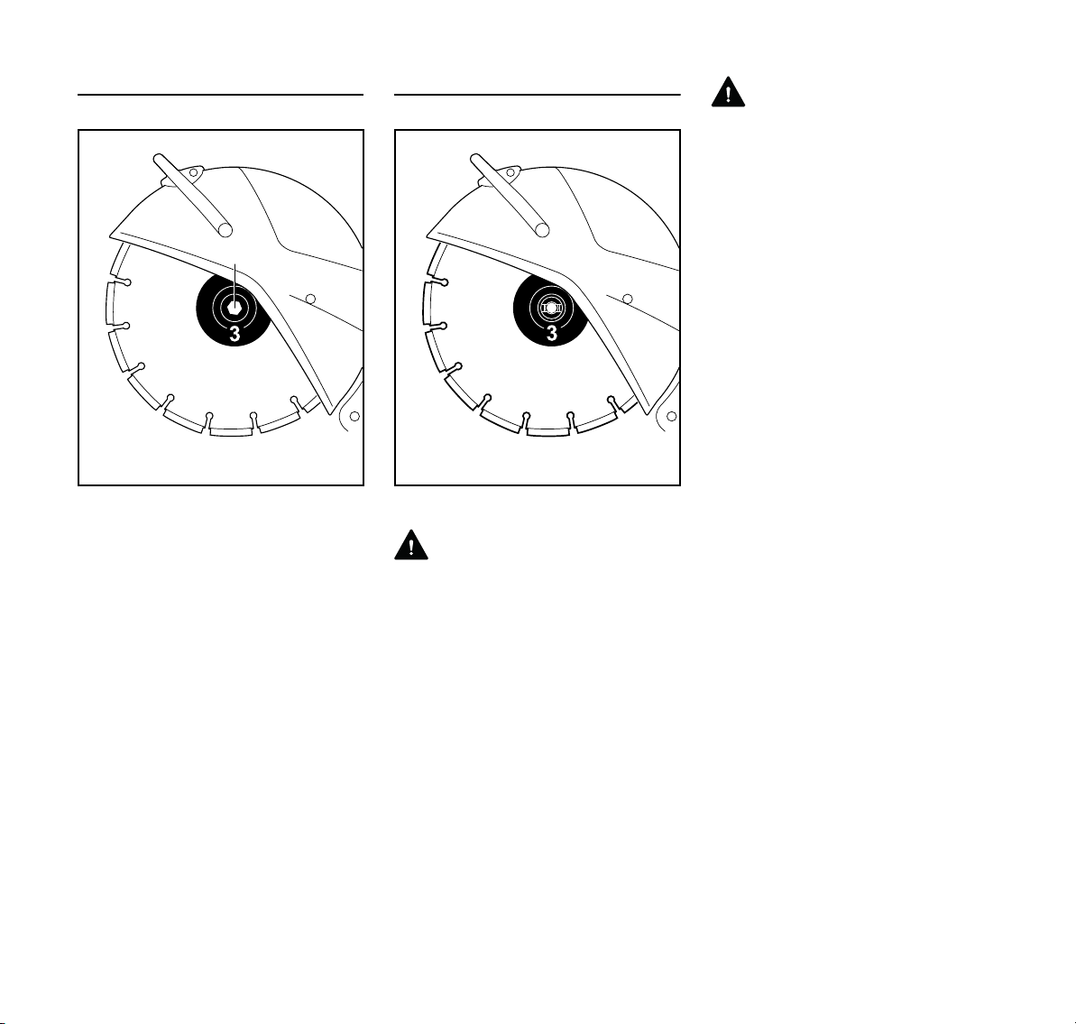
English
2
370BA053 KN
370BA054 KN
4
Removing a cutting wheel
N Use the combination wrench to
loosen and remove the hexagon
head screw (2)
N Remove the front thrust washer (3)
from the shaft together with the
cutting wheel
Fitting a new cutting wheel
WARNING
Never use two cutting wheels at the
same time. The uneven wear creates a
risk of breaking and an injury hazard!
N Fit the new cutting wheel (4)
WARNING
Note the arrows indicating the direction
of rotation on diamond cutting wheels.
N Fit the front thrust washer (3). The
catches of the front thrust
washer (3) must engage in the shaft
grooves.
N Screw in the hexagon bolt and
tighten it with the combination
wrench – if using a torque wrench,
refer to the "Specifications" for the
tightening torque
N Draw the locking pin out of the
V-belt guard
30
TS 410, TS 420
Page 33

English
Fuel
This engine is certified to operate on
unleaded gasoline and the STIHL twostroke engine oil at a mix ratio of 50:1.
Your engine requires a mixture of highquality gasoline and two-stroke air
cooled engine oil.
Use mid-grade unleaded gasoline with a
minimum octane rating of 89 ((R+M)/2)
and no more than 10% ethanol content.
Fuel with a lower octane rating may
increase engine temperatures. This, in
turn, increases the risk of piston seizure
and damage to the engine.
The chemical composition of the fuel is
also important. Some fuel additives not
only detrimentally affect elastomers
(carburetor diaphragms, oil seals, fuel
lines, etc.), but magnesium castings and
catalytic converters as well. This could
cause running problems or even
damage the engine. For this reason
STIHL recommends that you use only
high-quality unleaded gasoline!
Gasoline with an ethanol content of
more than 10% can cause running
problems and major damage in engines
and should not be used.
The ethanol content in gasoline affects
engine running speed – it may be
necessary to readjust the carburetor if
you use fuels with various ethanol
contents.
WARNING
To reduce the risk of personal injury
from loss of control and/or contact with
the running cutting tool, do not use your
unit with incorrect idle adjustment. At
correct idle speed, the cutting tool
should not move.
If your power tool shows an incorrect idle
adjustment, have your STIHL dealer
check your power tool and make proper
adjustments and repairs.
The idle speed and maximum speed of
the engine change if you switch from a
fuel with a certain ethanol content to
another fuel with a much higher or lower
ethanol content.
This problem can be avoided by always
using fuel with the same ethanol
content.
Use only STIHL two-stroke engine oil or
equivalent high-quality two-stroke
engine oils that are designed for use
only in air cooled two-cycle engines.
We recommend STIHL HP Ultra 2-Cycle
Engine Oil since it is specially
formulated for use in STIHL engines.
Do not use BIA or TCW rated (twostroke water cooled) mix oils or other
mix oils that state they are for use in both
water cooled and air cooled engines
(e.g., outboard motors, snowmobiles,
chain saws, mopeds, etc.).
WARNING
Take care when handling gasoline.
Avoid direct contact with the skin and
avoid inhaling fuel vapor. When filling at
the pump, first remove the container
from your vehicle and place the
container on the ground before filling. To
reduce the risk of sparks from static
discharge and resulting fire and/or
explosion, do not fill fuel containers that
are sitting in or on a vehicle or trailer.
The container should be kept tightly
closed in order to limit the amount of
moisture that gets into the mixture.
The machine‘s fuel tank should be
cleaned as necessary.
Fuel mix ages
Only mix sufficient fuel for a few days
work, not to exceed 30 days of storage.
Store in approved fuel-containers only.
When mixing, pour oil into the container
first, and then add gasoline. Close the
container and shake it vigorously by
hand to ensure proper mixing of the oil
with the fuel.
-
Gaso
line
US gal. US fl.oz.
12.6
2 1/2 6.4
5 12.8
Dispose of empty mixing-oil containers
only at authorized disposal locations.
Oil (STIHL 50:1 or equiva
lent high-quality oils)
-
TS 410, TS 420
31
Page 34
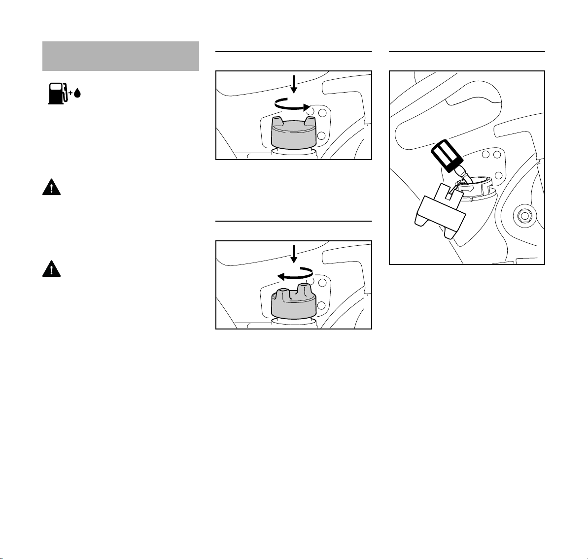
English
1.
2.
370BA017 KN
1.
2.
370BA018 KN
370BA019 KN
Fueling
Before fueling, clean the fuel filler cap
and the area around it so that dirt cannot
fall into the tank.
Thoroughly shake up the mixture in the
canister before fueling your machine.
WARNING
To avoid the risk of fire or other injuries
due to escaping gasoline vapors, open
the fuel filler cap carefully so that any
excess pressure in the tank can escape
slowly.
WARNING
Never use a tool to open the bayonet
cap. This could damage the cap and
cause fuel to leak out.
Do not spill any fuel and do not fill the
tank up to the brim.
Open the fuel filler cap
Press the cap down with your hand as
far as possible, turn it counterclockwise
(approx. 1/8 turn) and remove it.
Close the fuel filler cap
N Fit the cap and turn it until it
engages in the bayonet mount.
N Press the cap down with your hand
and turn it clockwise
(approx. 1/8 turn) until it engages
completely. Check cap for
tightness.
Change the fuel pickup body every year
N Drain the fuel tank.
N Pull the fuel pickup body out of the
tank with a hook and disconnect it
from the hose.
N Connect a new fuel pickup body to
the hose.
N Return the fuel pickup body to the
tank.
32
TS 410, TS 420
Page 35
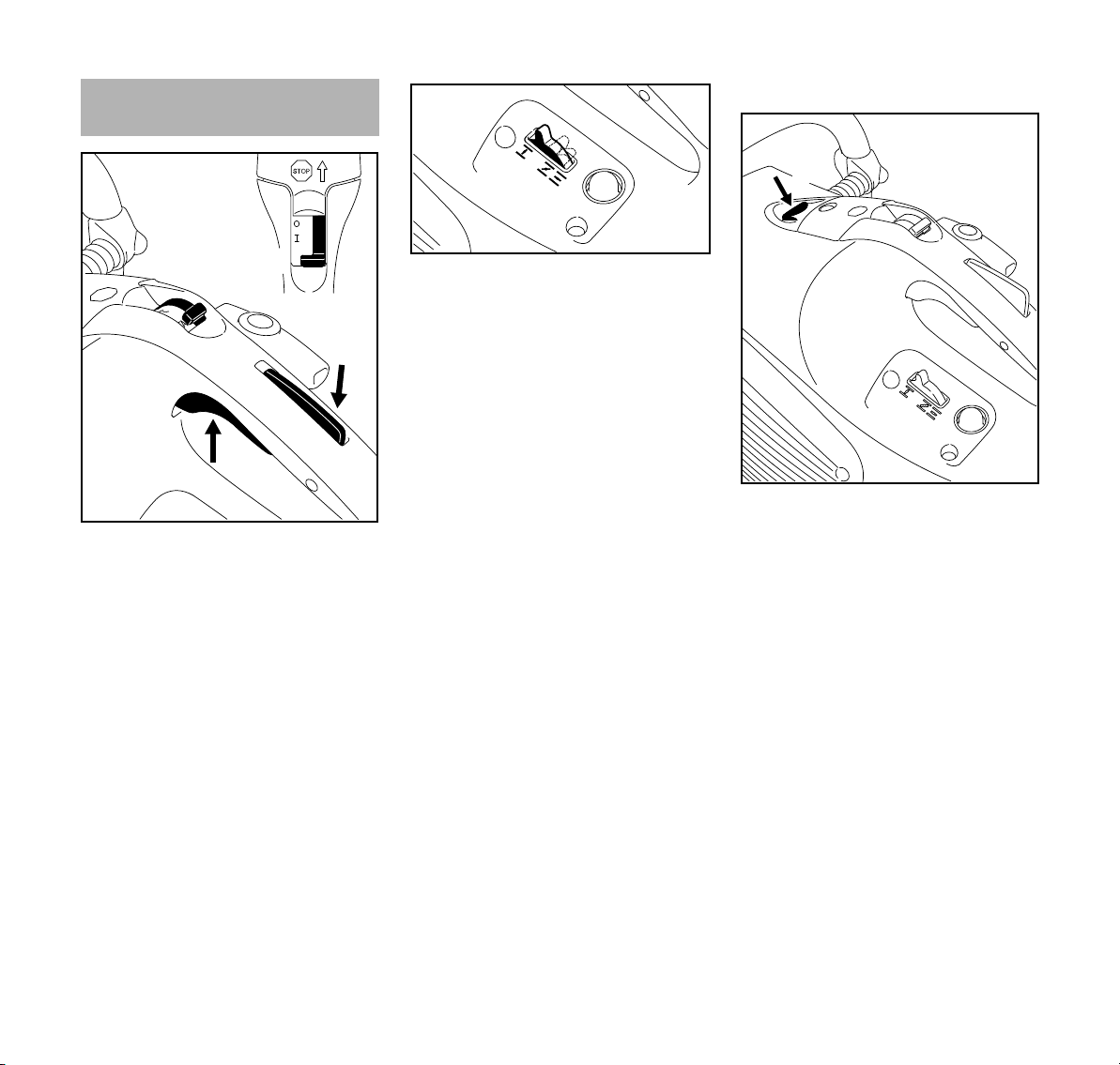
English
START
1
3
3
370BA020 KN
2
370BA055 KN
Choke
4
5
370BA101 KN
Starting / Stopping the
Engine
N Press throttle trigger lockout (1) and
throttle trigger (2) simultaneously
N Hold both triggers down
N Move the slide control (3) to START
and hold it in position too
N Release the throttle trigger, slide
control and throttle trigger lockout in
succession – starting throttle
position
Versions with decompression valve
N Set the choke (4) according to the
engine temperature
c If engine is cold
e if the engine is warm (even if the
engine is already running but is still
cold or if the warm engine was shut
off for less than 5 min)
f if the engine is hot (if the hot engine
was switched off for longer than
5min)
N Press the button (5) of the
decompression valve before each
starting procedure
TS 410, TS 420
33
Page 36
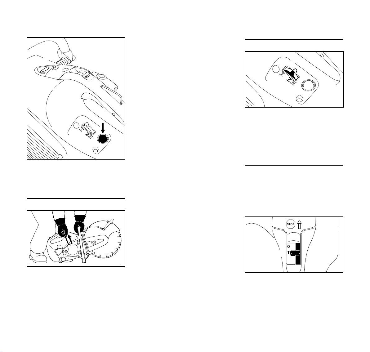
English
6
370BA102 KN
370BA092 KN
4
370BA057 KN
Choke
370BA058 KN
START
3
For all versions
N Press the bulb (6) of the manual fuel
pump 7-10 times – even when the
bulb is still filled with fuel
Starting
ground or any objects. There must
not be anyone within the swivel
range of the cut-off machine
N Make sure you have a firm footing
N Press the cut-off machine firmly
against the ground, holding the
handle with your left hand, thumb
wrapped round the handle
N Press the cut-off machine against
the ground with the right knee on the
shroud
N Pull the starter grip slowly with your
right hand until you feel it engage –
then give it a brisk strong pull – do
not pull out the starter rope all the
way
NOTICE
Do not let the starter grip snap back – it
may break! Guide it back into the
housing in the opposite direction so that
it can rewind properly.
When the engine has turned over for the
first time
N Set the choke lever (4) to f
N Press the button of the
decompression valve (depending
on version)
N continue cranking
Once the engine is running
N Squeeze throttle trigger fully and let
engine run at full throttle for
approx. 30 s
N When it has warmed up, set the
choke lever to e
N Place the cut-off machine carefully
on the ground, ensuring that the
abrasive wheel cannot touch the
34
N The slide control (3) moves to the
normal positionF when the throttle
trigger is squeezed
TS 410, TS 420
Page 37
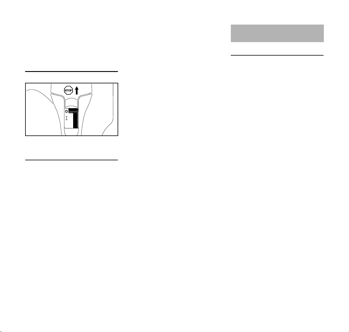
English
370BA059 KN
START
3
If the carburetor has been set correctly,
the abrasive wheel should not rotate
when the engine is idling.
The cut-off machine is now ready for
use.
Switching off the engine
N Slide control (3) toSTOP or 0
Additional hints on starting
If the engine does not start
The choke lever was not returned to f
in time after the engine turned over for
the first time.
N Slide control to START = starting
throttle position
N Set the choke lever to e = warm
start, even if the engine is cold
N Pull the starter rope through 10-20
times to ventilate the combustion
chamber
N Restart the engine
N Set the choke lever in accordance
with the engine temperature
N Restart the engine
Air Filter System
Basic information
The average filter life is more than
1 year. Do not dismantle the filter cover
or fit a new air filter unless there is a
noticeable loss of engine power.
In the long-life air filter system with the
cyclone pre-separation system, dirty air
is drawn in and deliberately rotated. The
larger and heavier particles carried in
the air are thus expelled and extracted.
Only pre-cleaned air enters the air filter
system and the result is extremely long
filter life.
If the tank has been drained completely
N Refuel
N Press the manual fuel pump bulb
7-10 times – even if it is full of fuel
TS 410, TS 420
35
Page 38
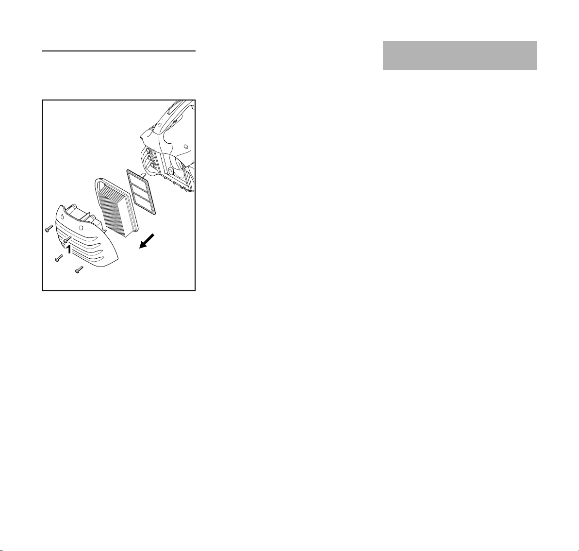
English
1
2
3
4
370BA028 KN
1
1
Replacing the air filter
Only if there is a noticeable loss of
engine power
N Choke lever to c
N Undo the screws (1)
N Remove the filter cover (2) and
clean it
N Remove the main filter (3)
N Remove the auxiliary filter (4) –
ensuring that dirt does not enter the
intake area
N Clean the filter area
N insert new auxiliary filter and new
N Refit the filter cover
N Tighten down the screws
main filter
Always use original STIHL air filters. The
high quality of these parts will ensure
trouble free operation, a long service life
for the engine and extremely long filter
life.
Engine Management
Exhaust emissions are controlled by the
design of the fundamental engine
parameters and components (e.g.
carburation, ignition, timing and valve or
port timing) without the addition of any
major hardware.
36
TS 410, TS 420
Page 39
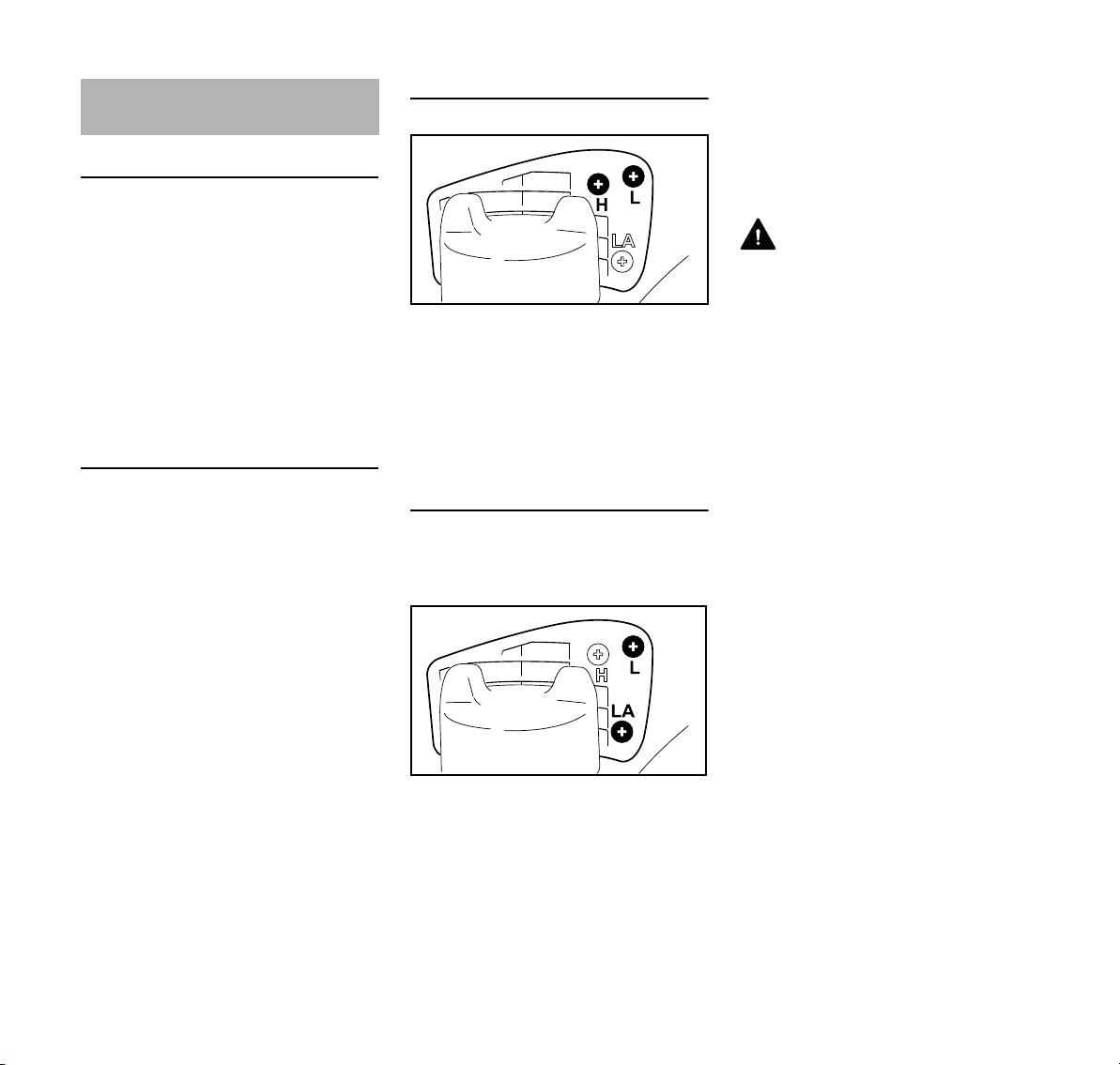
English
370BA029 KN
370BA090 KN
Adjusting the Carburetor
Basic information
The ignition system of this cut-off
machine is equipped with an electronic
maximum speed limiter. The maximum
speed cannot be increased beyond a
specified limit.
The carburetor comes from the factory
with a standard setting.
The carburetor has been adjusted for
optimum performance and fuel
efficiency in all operating states.
Preparing the machine
N Switch off the engine
N Check the air filter – clean or replace
it if necessary
N Check the spark arresting screen in
the muffler (present only in some
countries) – clean or replace it if
necessary
Standard setting
N Turn the high speed adjusting
screw (H) counterclockwise as far
as possible (max. 3/4 turn)
N Turn the low speed adjusting
screw (L) clockwise as far as
possible – then turn it 3/4 turn
counterclockwise
Setting the idle speed
N Make standard setting
N Start engine and let it warm up
Engine stops when idling
N Turn the idle speed adjusting
screw (LA) clockwise until the
abrasive wheel begins to rotate –
then turn it back 1 turn
Abrasive wheel runs when idling
N Turn the idle speed screw (LA)
counterclockwise until the abrasive
wheel stops running – then turn
another full turn in the same
direction
WARNING
If the abrasive wheel continues to keep
rotating in idle even after adjustment,
have the cut-off machine checked by a
servicing dealer.
Speed erratic when idling; poor
acceleration (despite adjustment to LA
setting)
The idle setting is too lean.
N Turn the low speed adjusting
screw (L) approx. 1/4 turn
counterclockwise until the engine
runs and accelerates smoothly –
max. up to the stop
Idle speed cannot be increased
sufficiently via the idle speed adjusting
screw (LA), engine stops when
changing from part-load to idle speed
The idle setting is too rich.
N Turn low speed adjusting screw (L)
approx. 1/4 turn clockwise.
Whenever the low speed adjusting
screw (L) has been adjusted, it is usually
also necessary to readjust the idle
speed adjusting screw (LA).
TS 410, TS 420
37
Page 40
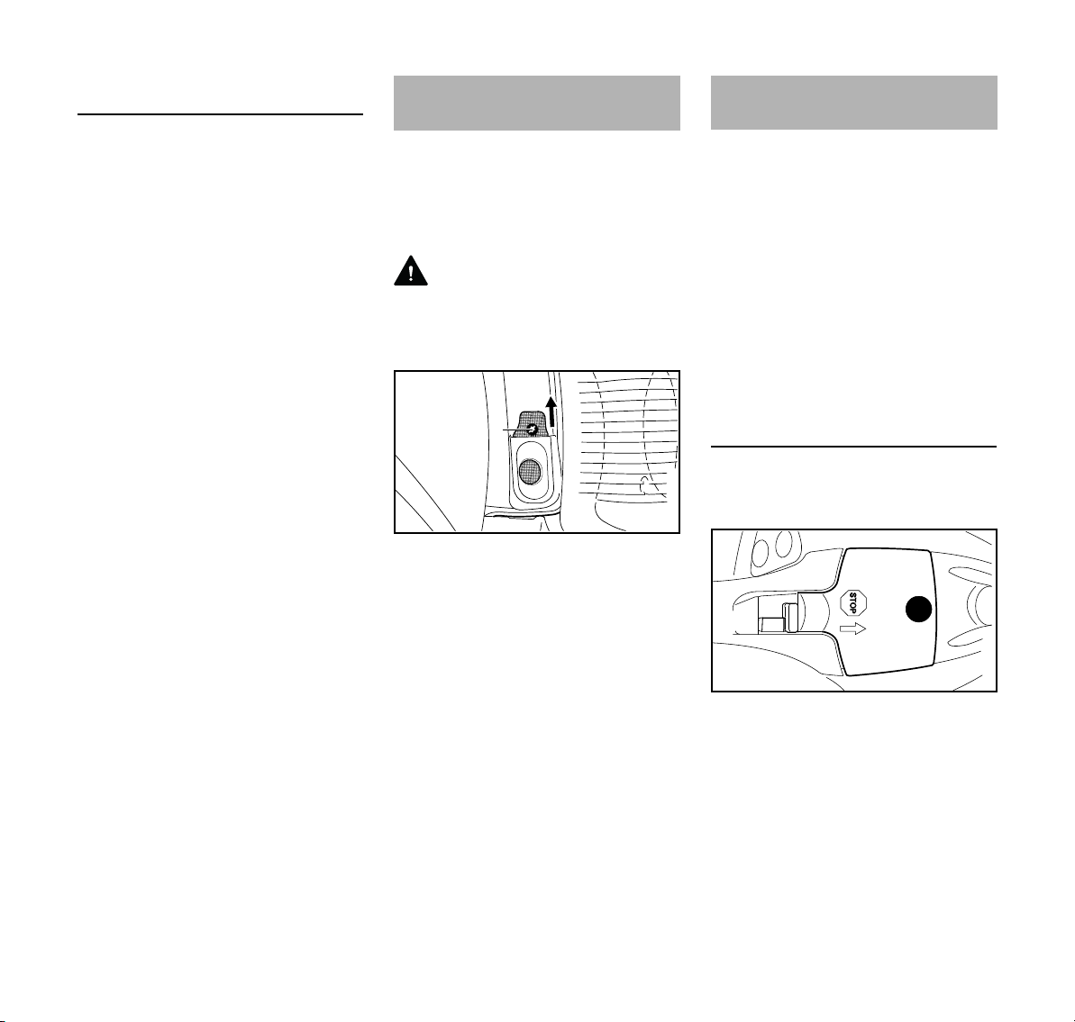
English
2
370BA031 KN
1
1307BA030 KN
1
2
Correcting the carburetor setting for use
at high altitudes
The setting may have to be marginally
corrected if engine performance is
unsatisfactory at high altitudes:
N Make standard setting
N Let the engine warm up
N Turn the high speed adjusting
screw (H) slightly clockwise (leaner)
– max. up to the stop
NOTICE
After descending from a high altitude,
restore the carburetor setting to the
standard setting.
If you make the setting too lean it will
increase the risk of engine damage
through lack of lubrication and
overheating.
Spark Arresting Screen in
Muffler
In some countries, the mufflers are fitted
with a spark arresting screen.
N If engine performance deteriorates,
check the spark arresting screen in
the muffler
WARNING
Wait until engine has cooled completely
before performing the following
operations.
N Remove screw (1)
N Pull the spark arresting screen (2)
upwards out of the muffler
N Clean the soiled spark arresting
screen
N If the screen is damaged or heavily
carbonized, fit a new one
N Refit the spark arresting screen in
reverse order of steps
Spark Plug
If engine is down on power, difficult to
start or runs poorly at idling speed, first
check the spark plug.
Fit a new spark plug after approx. 100
operating hours or earlier if the
electrodes are badly eroded.
Wrong fuel mix (too much engine oil in
the gasoline), a dirty air filter and
unfavorable running conditions (mostly
at part throttle etc.) affect the condition
of the spark plug. These factors cause
deposits to form on the insulator nose
which may result in trouble in operation.
Removing the spark plug
N Switch off the engine – move stop
switch to STOP or 0
N Unscrew screw (1) and remove
cap (2) – screw (1) is secured in the
cap (2) to prevent loss
38
TS 410, TS 420
Page 41
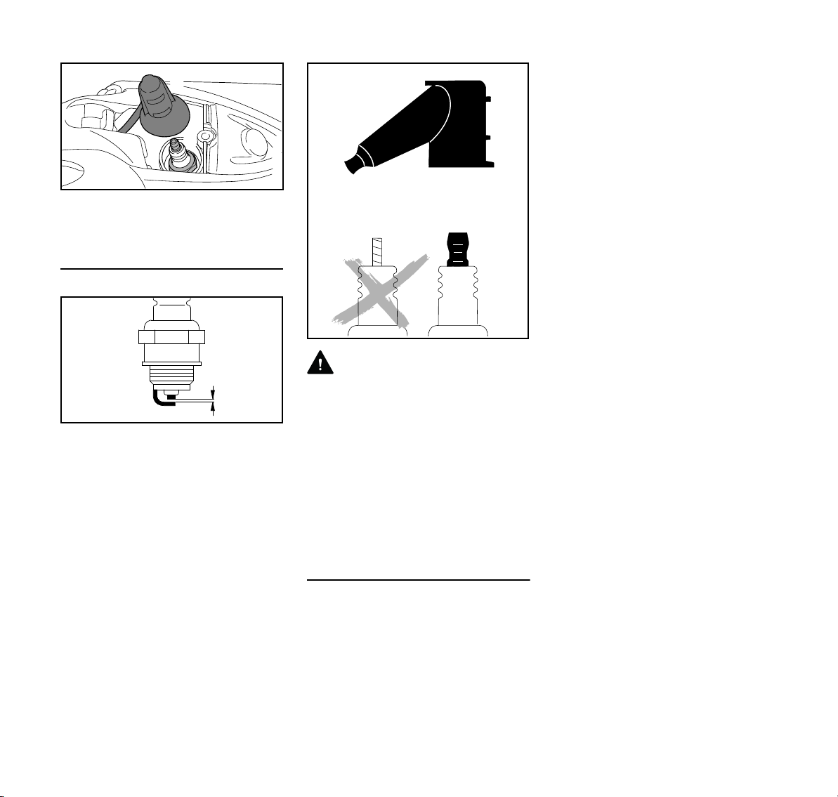
N Remove the spark plug boot (3).
4
1307BA031 KN
3
000BA039 KN
A
1
2
000BA071 KN
N Unscrew the spark plug (4).
Checking the Spark Plug
N Clean dirty spark plug.
N Check electrode gap (A) and
readjust if necessary – see
"Specifications."
N Use only resistor type spark plugs of
the approved range.
Rectify problems that have caused
fouling of spark plug:
– too much oil in fuel mix,
– dirty air filter,
– unfavorable running conditions, e.g.
operating at part load.
English
N Press the spark plug boot firmly
onto the spark plug
N Position the cap for the spark plug
boot and screw it down
WARNING
To reduce the risk of fire and burn injury,
use only spark plugs authorized by
STIHL. Always press spark plug boot (1)
snugly onto spark plug terminal (2) of the
proper size. (Note: If terminal has
detachable SAE adapter nut, it must be
securely attached.) A loose connection
between spark plug boot and ignition
wire connector in the boot may create
arcing that could ignite combustible
fumes and cause a fire.
Installing the spark plug
N Fit the spark plug by hand and
screw it in
N Tighten spark plug with combination
wrench
TS 410, TS 420
39
Page 42

English
1
1
1
2
370BA037 KN
0
4
3
370BA061 KN
6
370BA062 KN
1
5
1
1
7
8
370BA063 KN
9
Rewind Starter Replacing the V-belt
To help prolong the wear life of the
starter rope, observe the following
points:
N Pull the starter rope only in the
direction specified.
N Do not pull the rope over the edge of
the guide bushing.
N Do not pull out the rope more than
specified.
N Do not allow the starter grip to snap
back, guide it back into the housing
slowly – see chapter on "Starting /
Stopping the Engine."
Have a damaged starter rope replaced
by your dealer before it breaks
completely. STIHL recommends that
you have servicing and repair work
carried out exclusively by an authorized
STIHL servicing dealer.
N Undo the nuts (1)
N Turn the tensioning nut (2)
counterclockwise with the
combination wrench –
approx. 1/4 turn, as far as it will
go = 0
N Unscrew the nuts (1)
N Remove the starter cover (5)
N Do not remove the "cast arm and
guard" (6) – hold it in place on the
studs until the starter cover is fitted
back in position
N Remove the defective V-belt
N Carefully insert the new V-belt (7)
N Pull the water hose out of the guide
in the V-belt guard
N Remove screw (3)
N Raise the V-belt guard (4) slightly
and pull it off to the front
N Remove the V-belt from the front
pulley
40
on the V-belt pulley (8) on the
engine and the front V-belt
pulley (9)
NOTICE
The belt action must run smoothly.
TS 410, TS 420
Page 43

English
10
1
10
10
370BA064 KN
1
5
1
4
3
370BA065 KN
1307BA027 KN
N Fit the starter cover (5) over the
studs (10)
N Tighten up the nuts (1) by hand
N Push the V-belt guard (4) into place
N Screw in the bolt (3) and tighten up
N Insert the water hose into the guide
in the V-belt guard (arrow) from the
shut-off cock towards the guard –
avoid tight radiuses
Continue as described in the chapter
“Tensioning the V-belt”.
Cut-off machine cart
The cut-off machine can be mounted on
the STIHL cut-off machine cart FW 20
(special accessory) in a few easy steps.
The cut-off machine cart makes it easier
to
– repair damaged roadways
– apply roadway markings
– cut expansion joints
Storing the Machine
If the machine is to remain out of use for
approx. 3 months or more
N Drain and clean the fuel tank in a
well ventilated place
N Dispose of fuel in accordance with
the regulations and having regard
for the environment
N Run the engine until the carburetor
is dry, this helps to prevent the
carburetor diaphragms sticking
together
N Remove the abrasive wheel
N Thoroughly clean the machine
N Store machine in a safe and dry
place. Protect against unauthorized
use (e. g., by children)
TS 410, TS 420
41
Page 44

English
Maintenance and Care
The following maintenance intervals apply in normal operating conditions. The
specified intervals must be shortened accordingly when working for longer than
normal or under difficult cutting conditions (extensive dust, etc.).
before starting work
at the end of work and/or
daily
Whenever tank is refilled
Weekly
Monthly
Yearly
if not functioning properly
Complete machine
Operating controls Check operation XX
Manual fuel pump (if fitted)
Fuel pick-up body in fuel tank
Fuel tank Clean X
Ribbed V-belt
Air filter (all filter components) Replace Only if there is a noticeable loss of engine power
Cooling air intake slits Clean X
Cylinder fins
Spark arresting screen
Water attachment
Carburetor
Spark plug
All accessible screws, nuts and bolts (not
adjusting screws)
2)
in muffler
Visual inspection (condition, leaks) XX
Clean X
Check X
Have repaired by a specialist dealer
test, check X
Replace XXX
Clean / retension XX
Replace XX
Have them cleaned by a specialist
1)
dealer
test, check X
Clean or replace X
test, check xx
Have them maintained by a specialist
1)
dealer
Check idle adjustment – abrasive
wheel must not rotate
Readjust idle speed X
Adjust electrode gap X
Replace after 100 hours’ operation
Retighten XX
1)
X
XX
X
x
If damaged
As required
42
TS 410, TS 420
Page 45

The following maintenance intervals apply in normal operating conditions. The
specified intervals must be shortened accordingly when working for longer than
normal or under difficult cutting conditions (extensive dust, etc.).
before starting work
at the end of work and/or
daily
Whenever tank is refilled
Weekly
Monthly
Yearly
if not functioning properly
test, check XXX
Antivibration elements
Abrasive wheel
Supports/rubber buffers (underneath the
machine)
Warning labels Replace X
1)
STIHL recommends STIHL specialist dealers
2)
present only in some countries
Have them replaced by a specialist
1)
dealer
test, check XX
Replace XX
test, check X
Replace XX
If damaged
X
English
As required
TS 410, TS 420
43
Page 46

English
18
17
D
E
C
5
10
#
21
20
19
13
16
11
9
8
7
4
A
14
15
B
3
370BA103 KN
1
2
6
Main Parts
1 Rear Handle
2 Throttle Trigger Lockout
3 Throttle Trigger
4 Slide Control
5 Starter Grip
6 Carburetor Adjusting Screws
7 Fuel Filler Cap
8 Water Attachment
9 Tensioning Nut
10 Adjusting Lever
11 Abrasive Wheel
12 Front Thrust Washer
13 Guard
14 Muffler
15 Spark Arresting Screen
16 Front Handle
17 Decompression Valve
18 Cap for Spark Plug Boot
19 Choke Lever
20 Manual Fuel Pump
21 Filter Cover
# Serial Number
A Warning Label
B Warning Label
C Warning Label
D Warning Label
E Warning Label
1)
44
1)
Depending on Model
TS 410, TS 420
Page 47

English
Definitions
1 Rear Handle
The support handle for the right
hand.
2 Throttle Trigger Lockout
Must be depressed before the
throttle trigger can be activated.
3 Throttle Trigger
Controls the speed of the engine.
4 Slide Control
For starting throttle, run and stop.
Keeps the throttle partially open
during starting and switches off the
ignition to stop the engine.
5 Starter Grip
The grip of the pull starter, for
starting the engine.
6 Carburetor Adjusting Screws
For tuning the carburetor.
7 Fuel Filler Cap
For closing the fuel tank.
8 Water Attachment
For connection of water supply for
wet cutting.
9 Tensioning Nut
For tensioning the ribbed belt.
10 Adjusting Lever
To adjust the wheel guard in a way
that sparks, dust, cutting debris or
wheel fragments are directed away
from the operator.
11 Abrasive Wheel
Can either be a composite abrasive
wheel or a diamond abrasive wheel.
12 Front Thrust Washer
Distributes clamping pressure of
mounting nut evenly over cutting
wheel.
13 Guard
Guards the wheel and deflects
sparks, dust, cutting debris or wheel
fragments.
14 Muffler
Reduces engine exhaust noises
and diverts exhaust gases away
from operator.
15 Spark Arresting Screen
Designed to reduce the risk of fire.
16 Front Handle
Handlebar for the left hand of the
power tool.
17 Decompression Valve
Releases compression pressure to
make engine starting easier - when
activated.
18 Cap for Spark Plug Boot
The spark plug boot connects the
spark plug with the ignition lead.
19 Choke Lever
Eases engine starting by enriching
mixture.
20 Manual Fuel Pump
Provides additional fuel feed for a
cold start.
21 Filter Cover
Covers and protects the air filter
element.
Clutch
Couples engine to the belt pulley
when engine is accelerated beyond
idle speed. (Not illustrated)
Belt Pulley
The wheel that drives the ribbed belt
and the abrasive wheel. (Not
illustrated)
Anti-Vibration System
The anti-vibration system includes a
number of anti-vibration elements
designed to reduce the
transmission of vibrations created
by the engine and cutting process to
the operator's hands. (Not
illustrated)
TS 410, TS 420
45
Page 48

English
Specifications
EPA / CEPA
The Emission Compliance Period
referred to on the Emissions
Compliance Label indicates the number
of operating hours for which the engine
has been shown to meet Federal
emission requirements.
Category
A = 300 hours
B = 125 hours
C = 50 hours
CARB
The Emission Compliance Period used
on the CARB-Air Index Label indicates
the terms:
Extended = 300 hours
Intermediate = 125 hours
Moderate = 50 hours
Engine
STIHL single cylinder two-stroke engine
TS 410
Displacement: 4.07 cu. in.
(66.7 cm
3)
Cylinder bore: 1.97 in. (50 mm)
Piston stroke: 1.34 in. (34 mm)
Engine power accord
ing to ISO 7293:
-
4.3 hp (3.2 kW)
at 9000 rpm
Idling speed: 2500 rpm
Maximum spindle
speed: 5350 rpm
TS 420
Displacement: 4.07 cu. in.
(66.7 cm
3)
Cylinder bore: 1.97 in. (50 mm)
Piston stroke: 1.34 in. (34 mm)
Engine power accord
ing to ISO 7293:
-
4.3 hp (3.2 kW)
at 9000 rpm
Idling speed: 2500 rpm
Maximum spindle
speed: 5350 rpm
Ignition system
Electronic magneto ignition
Spark plug
(suppressed): Bosch WSR 6 F
Electrode gap: 0.02 in.
(0.5 mm)
Fuel system
All position diaphragm carburetor with
integral fuel pump
Fuel tank capacity: 24.0 oz
(0.71 l)
Air filter
Main filter (paper filter) and flocked wire
mesh auxiliary filter
Weight
Without fuel, without abrasive wheel,
with water attachment
TS 410: 20.7 lbs
(9.4 kg)
TS 420: 21.2 lbs
(9.6 kg)
Without fuel, without abrasive wheel,
with electronic water control
TS 410: 21.8 lbs
(9.9 kg)
TS 420: 22.3 lbs
(10.1 kg)
Abrasive wheels
The quoted maximum permissible
operating speed of the abrasive wheel
must be greater than or equal to the
maximum spindle speed of the cut-off
machine used.
Abrasive wheels (TS 410)
Outside diameter: 12 in.
(300 mm)
Max. thickness: 0.189 in.
(4.8 mm)
Bore diameter/spindle
diameter:
0.787 in.
(20 mm)
Tightening torque: 22 lbf ft
(30 Nm)
46
TS 410, TS 420
Page 49
English
000BA073 KN
Composite resin abrasive wheels
Minimum outside diameter of
thrust washers:
4.06 in.
(103 mm)
Max. depth of cut: 3.9 in.
(100 mm)
Diamond abrasive wheels
Minimum outside diameter of
thrust washers:
4.06 in.
(103 mm)
Max. depth of cut: 3.9 in.
(100 mm)
Abrasive wheels (TS 420)
Outside diameter: 14 in.
(350 mm)
Max. thickness: 0.189 in.
(4.8 mm)
Bore diameter/spindle
diameter:
0.787 in.
(20 mm)
Tightening torque: 22 lbf ft
(30 Nm)
Composite resin abrasive wheels
Minimum outside diameter of
thrust washers:
4.06 in.
(103 mm)
Max. depth of cut: 4.9 in.
(125 mm)
Maintenance and Repairs Disposal
Users of this unit should carry out only
the maintenance operations described
in this manual. STIHL recommends that
other repair work be performed only by
authorized STIHL servicing dealers.
Warranty claims following repairs can be
accepted only if the repair has been
performed by an authorized STIHL
servicing dealer using genuine STIHL
replacement parts.
Genuine STIHL parts can be identified
by the STIHL part number, the
{ logo and, in some cases, by
the STIHL parts symbol K. The
symbol may appear alone on small
parts.
Observe all country-specific waste
disposal rules and regulations.
STIHL products must not be thrown in
the garbage can. Take the product,
accessories and packaging to an
approved disposal site for environmentfriendly recycling.
Contact your STIHL servicing dealer for
the latest information on waste disposal.
Diamond abrasive wheels
Minimum outside diameter of
thrust washers:
4.06 in.
(103 mm)
Max. depth of cut: 4.9 in.
(125 mm)
TS 410, TS 420
47
Page 50

English
STIHL Incorporated Federal
Emission Control Warranty
Statement
Your Warranty Rights and Obligations
The U.S. Environmental Protection
Agency (EPA) and STIHL Incorporated
are pleased to explain the Emission
Control System Warranty on your
equipment type engine. In the U.S. new
1997 and later model year small off-road
equipment engines must be designed,
built and equipped, at the time of sale, to
meet the U.S. EPA regulations for small
non road engines. The equipment
engine must be free from defects in
materials and workmanship which
cause it to fail to conform with U.S. EPA
standards for the first two years of
engine use from the date of sale to the
ultimate purchaser.
STIHL Incorporated must warrant the
emission control system on your small
off-road engine for the period of time
listed below provided there has been no
abuse, neglect or improper maintenance
of your small off-road equipment engine.
Your emission control system includes
parts such as the carburetor and the
ignition system. Also included may be
hoses, and connectors and other
emission-related assemblies.
Where a warrantable condition exists,
STIHL Incorporated will repair your
small off-road equipment engine at no
cost to you including diagnosis (if the
diagnostic work is performed at an
authorized dealer), parts and labor.
Manufacturer's Warranty Coverage
In the U.S., 1997 and later model year
small off-road equipment engines are
warranted for two years. If any emissionrelated part on your engine is defective,
the part will be repaired or replaced by
STIHL Incorporated free of charge.
Owner's Warranty Responsibilities
As the small off-road equipment engine
owner, you are responsible for the
performance of the required
maintenance listed in your instruction
manual. STIHL Incorporated
recommends that you retain all receipts
covering maintenance on your small offroad equipment engine, but STIHL
Incorporated cannot deny warranty
solely for the lack of receipts or for your
failure to ensure the performance of all
scheduled maintenance.
Any replacement part or service that is
equivalent in performance and durability
may be used in non-warranty
maintenance or repairs, and shall not
reduce the warranty obligations of the
engine manufacturer.
As the small off-road equipment engine
owner, you should be aware, however,
that STIHL Incorporated may deny you
warranty coverage if your small off-road
equipment engine or a part has failed
due to abuse, neglect, improper
maintenance or unapproved
modifications.
You are responsible for presenting your
small off-road equipment engine to a
STIHL service center as soon as a
problem exists. The warranty repairs will
be completed in a reasonable amount of
time, not to exceed 30 days.
If you have any questions regarding your
warranty rights and responsibilities,
please contact a STIHL customer
service representative at 1-800-4678445 or you can write to
STIHL Inc.,
536 Viking Drive, P.O. Box 2015,
Virginia Beach, VA 23450-2015
www.stihlusa.com
Coverage by STIHL Incorporated
STIHL Incorporated warrants to the
ultimate purchaser and each
subsequent purchaser that your small
off-road equipment engine will be
designed, built and equipped, at the time
of sale, to meet all applicable
regulations. STIHL Incorporated also
warrants to the initial purchaser and
each subsequent purchaser that your
engine is free from defects in materials
and workmanship which cause the
engine to fail to conform with applicable
regulations for a period of two years.
Warranty Period
The warranty period will begin on the
date the utility equipment engine is
purchased by the initial purchaser and
you have signed and sent back the
warranty card to STIHL.
If any emission-related part on your
engine is defective, the part will be
replaced by STIHL Incorporated at no
cost to the owner. Any warranted part
which is not scheduled for replacement
48
TS 410, TS 420
Page 51

English
as required maintenance, or which is
scheduled only for regular inspection to
the effect of "repair or replace as
necessary" will be warranted for the
warranty period. Any warranted part
which is scheduled for replacement as
required maintenance will be warranted
for the period of time up to the first
scheduled replacement point for that
part.
Diagnosis
You, as the owner, shall not be charged
for diagnostic labor which leads to the
determination that a warranted part is
defective. However, if you claim
warranty for a component and the
machine is tested as non-defective,
STIHL Incorporated will charge you for
the cost of the emission test. Mechanical
diagnostic work will be performed at an
authorized STIHL servicing dealer.
Emission test may be performed either
at STIHL Incorporated or at any
independent test laboratory.
Warranty Work
STIHL Incorporated shall remedy
warranty defects at any authorized
STIHL servicing dealer or warranty
station. Any such work shall be free of
charge to the owner if it is determined
that a warranted part is defective.
Any manufacturer-approved or
equivalent replacement part may be
used for any warranty maintenance or
repairs on emission-related parts and
must be provided without charge to the
owner. STIHL Incorporated is liable for
damages to other engine components
caused by the failure of a warranted part
still under warranty.
The following list specifically defines the
emission-related warranted parts:
– Air Filter
– Carburetor (if applicable)
– Fuel Pump
– Choke (Cold Start Enrichment
System) (if applicable)
– Control Linkages
– Intake Manifold
– Magneto or Electronic Ignition
System (Ignition Module or
Electronic Control Unit)
– Fly Wheel
– Spark Plug
– Injection Valve (if applicable)
– Injection Pump (if applicable)
– Throttle Housing (if applicable)
– Cylinder
– Muffler
– Catalytic Converter (if applicable)
– Fuel Tank
– Fuel Cap
– Fuel Line
– Fuel Line Fittings
– Clamps
– Fasteners
Where to make a Claim for Warranty
Service
Bring the product to any authorized
STIHL servicing dealer and present the
signed warranty card.
Maintenance Requirements
The maintenance instructions in this
manual are based on the application of
the recommended 2-stroke fuel-oil
mixture (see also instruction "Fuel").
Deviations from this recommendation
regarding quality and mixing ratio of fuel
and oil may require shorter maintenance
intervals.
Limitations
This Emission Control Systems
Warranty shall not cover any of the
following:
N repair or replacement required
because of misuse, neglect or lack
of required maintenance,
N repairs improperly performed or
replacements not conforming to
STIHL Incorporated specifications
that adversely affect performance
and/or durability, and alterations or
modifications not recommended or
approved in writing by STIHL
Incorporated,
and
N replacement of parts and other
services and adjustments
necessary for required maintenance
at and after the first scheduled
replacement point.
TS 410, TS 420
49
Page 52
English
TM
STIHL
Injection
Trademarks
STIHL Registered Trademarks
®
STIHL
{
K
The color combination orange-grey
(U.S. Registrations #2,821,860;
#3,010,057, #3,010,058, #3,400,477;
and #3,400,476)
AutoCut
EASYSTART
FARM BOSS
iCademy
MAGNUM
MasterWrench Service
MotoMix
®
®
®
®
®
®
®
OILOMATIC
Rock Boss
STIHL Cutquik
STIHL DUROMATIC
STIHL Quickstop
STIHL ROLLOMATIC
STIHL WOOD BOSS
TIMBERSPORTS
WOOD BOSS
YARD BOSS
®
®
®
®
®
®
®
®
®
®
Some of STIHL’s Common Law
Trademarks
4-MIX ™
BioPlus ™
Easy2Start ™
EasySpool ™
ElastoStart ™
Ematic ™
FixCut ™
HT Plus ™
IntelliCarb ™
Master Control Lever ™
Micro ™
Pro Mark ™
Quad Power ™
Quiet Line ™
STIHL Arctic ™
STIHL Compact ™
STIHL HomeScaper Series ™
STIHL Interchangeable Attachment
Series ™
STIHL M-Tronic ™
STIHL MiniBoss ™
STIHL MotoPlus 4 ™
STIHL Multi-Cut HomeScaper Series ™
STIHL OUTFITTERS ™
STIHL PICCO ™
STIHL PolyCut ™
STIHL PowerSweep ™
STIHL Precision Series ™
STIHL Protech ™
STIHL RAPID ™
STIHL SuperCut ™
STIHL Territory ™
TapAction ™
TrimCut ™
This listing of trademarks is subject to
change.
Any unauthorized use of these
trademarks without the express written
consent of
ANDREAS STIHL AG & Co. KG,
Waiblingen is strictly prohibited.
50
TS 410, TS 420
Page 53

Contenido
español / EE.UU
Acerca de este manual de
instrucciones 52
Medidas de seguridad y técnicas
de manejo 53
Ejemplos de usos 69
Discos de corte 73
Discos de corte de resina
compuesta 73
Discos de corte adiamantados 73
Manual de instrucciones originalImpreso en papel libre de cloro.
Sistema de control electrónico de
agua 77
Armado del brazo fundido y
protector 78
Tensado de la correa trapezoidal
nervada 82
Colocación / sustitución de un disco
abrasivo 83
Combustible 84
Llenado de combustible 86
Arranque / parada del motor 87
Sistema de filtro de aire 89
Gestión del motor 90
Ajuste del carburador 91
Las tintas contienen aceites vegetales, el papel es reciclable.
Chispero en el silenciador 92
Bujía 93
Dispositivo de arranque 94
Sustitución de la correa trapezoidal 94
Carro para sierra 95
Almacenamiento de la máquina 96
Información para mantenimiento 97
Componentes importantes 99
Especificaciones 101
Información de reparación 102
Desecho 103
Declaración de garantía de STIHL
Incorporated sobre sistemas de
control de emisiones según normas
Federales 103
Marcas comerciales 106
Permita que solamente las personas
que comprenden enteramente la
materia descrita en este manual
manejen su tronzadora.
Para obtener el rendimiento y
satisfacción máximos del podador de
varilla STIHL, es importante que lea,
comprenda y respete las medidas de
seguridad y las instrucciones de uso y
mantenimiento dadas en el capítulo
"Medidas de seguridad y técnicas de
uso", antes de usar su tronzadora. Para
información adicional, puede acudir a
www.stihlusa.com.
Comuníquese con su representante de
STIHL o el distribuidor de STIHL para su
zona si no se entiende alguna de las
instrucciones dadas en el presente
manual.
ADVERTENCIA
Dado que la tronzadora es una
herramienta de corte motorizada de
gran velocidad, es necesario tomar
medidas especiales de seguridad para
reducir el riesgo de lesiones. El uso
descuidado o inadecuado puede causar
lesiones graves e incluso mortales.
{
© ANDREAS STIHL AG & Co. KG, 2014
0458-370-8621-G. VB2.K14.
0000000893_014_EA
TS 410, TS 420
Este manual de instrucciones está protegido por derechos de propiedad intelectual. Todos los derechos reservados, especial
mente los derechos de reproducción, traducción y procesamiento con sistemas electrónicos.
-
51
Page 54
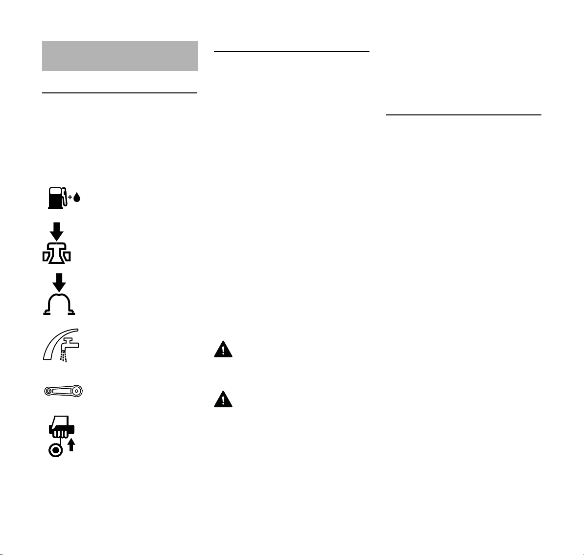
español / EE.UU
Acerca de este manual de
instrucciones
Pictogramas
Todos los pictogramas que se
encuentran fijados o grabados en la
máquina se explican en este manual.
Según el modelo, los pictogramas
siguientes pueden aparecer en su
máquina.
Tanque de combustible
que contiene la mezcla
de combustible y aceite
Presione para accionar la
válvula de
descompresión
Presione para accionar la
bomba manual de
combustible
Accesorio para agua,
control de caudal
Tuerca tensora para acti
var la correa impulsora
Mango de cuerda de
arranque
Símbolos en el texto
Muchas de las instrucciones de uso y
seguridad vienen acompañadas de
ilustraciones.
Los pasos individuales o
procedimientos descritos en el manual
pueden estar señalados en diferentes
maneras:
N Se usa un punto para denotar un
paso o procedimiento.
Una descripción de un paso o
procedimiento que se refiere
directamente a una ilustración puede
contener números de referencia que
aparecen en la ilustración. Ejemplo:
N Suelte el tornillo (1).
N Palanca (2) ...
Además de las instrucciones de uso, en
este manual pueden encontrarse
párrafos a los que usted debe prestar
atención especial. Tales párrafos están
marcados con los símbolos y las
palabras identificadoras que se
describen a continuación.
PELIGRO
Indica un riesgo inminente de lesiones
-
graves o mortales.
ADVERTENCIA
Identifica una situación de peligro que,
al no evitarse, puede resultar en
lesiones graves o mortales.
INDICACIÓN
Indica el riesgo de daños a la propiedad,
incluyendo a la máquina o sus
componentes.
Mejoramientos técnicos
La filosofía de STIHL es mejorar
continuamente todos sus productos.
Como resultado de ello, periódicamente
se introducen cambios de diseño y
mejoras. Por lo tanto, es posible que
algunos cambios, modificaciones y
mejoras no se describen en este
manual. Si las características de
funcionamiento o la apariencia de su
máquina difieren de las descritas en
este manual, comuníquese con el
concesionario STIHL para obtener la
ayuda que requiera.
52
TS 410, TS 420
Page 55
español / EE.UU
Medidas de seguridad y
técnicas de manejo
El uso de cualquier tron
zadora puede ser
peligroso. Dado que la
sierra es una herramienta
de corte motorizada que
funciona a gran veloci
dad, es necesario tomar
medidas especiales de
seguridad para reducir el
riesgo de lesiones y de
incendios.
Es importante que usted
lea, comprenda bien y
respete las siguientes
advertencias y medidas
de seguridad. Lea el
manual de instrucciones
y las precauciones de
seguridad
periódicamente.
ADVERTENCIA
El uso descuidado o inadecuado de
cualquier tronzadora puede causar
lesiones graves e incluso mortales.
Pida a su concesionario STIHL que le
enseñe el manejo de la tronzadora.
Respete todas las disposiciones,
reglamentos y normas de seguridad
nacionales, estatales y locales del caso.
ADVERTENCIA
Su tronzadora es solamente para uso
por profesionales. No preste ni alquile
nunca su tronzadora sin entregar el
manual de instrucciones. Asegúrese de
-
que todas las personas que utilicen la
máquina hayan comprendido la
información que contiene este manual.
-
Un operador novato deberá recibir
capacitación práctica antes de utilizar la
máquina. Las empresas deberán
establecer un programa de capacitación
para los operadores de tronzadoras
portátiles de mano con motor a gasolina,
a fin de garantizar la seguridad en el uso
de estas máquinas y la selección de los
accesorios de corte adecuados. Las
medidas de seguridad y avisos
contenidos en este manual se refieren al
uso de todas las sierras Cutquik de
STIHL actuales.
ADVERTENCIA
Use su tronzadora solamente para los
propósitos autorizados. Por ejemplo, no
es adecuada para cortar madera u
objetos de madera. El uso indebido
puede resultar en lesiones personales o
daños a la propiedad, incluso daños de
la máquina.
ADVERTENCIA
Nunca permita a menores de edad que
usen una tronzadora. No se debe
permitir la proximidad de otros,
especialmente niños y animales, donde
se esté utilizando la tronzadora. Nunca
deje desatendida una tronzadora en
marcha.
Los distintos modelos pueden contar
con piezas y controles diferentes. Vea la
sección correspondiente de su manual
de instrucciones para tener una
descripción de los controles y la función
de cada componente de su modelo de
tronzadora.
El uso seguro de una tronzadora
involucra a:
1. el operador
2. la herramienta motorizada
3. el uso de la herramienta
motorizada.
EL OPERADOR
Condición física
Usted debe estar en buenas
condiciones físicas y psíquicas y no
encontrarse bajo la influencia de
ninguna sustancia (drogas, alcohol,
etc.) que le pueda restar visibilidad,
destreza o juicio. No maneje la
tronzadora cuando está fatigado. Esté
atento - Si se fatiga mientras se usa la
tronzadora, tómese un descanso; la
fatiga puede dar por resultado la pérdida
del control. El uso de cualquier
tronzadora es fatigoso. Si usted padece
de alguna condición que puede
agravarse con el trabajo fatigoso,
consulte a un médico antes de usar una
tronzadora.
ADVERTENCIA
El uso prolongado de una tronzadora (u
otras máquinas) expone al operador a
vibraciones que pueden provocar el
fenómeno de Raynaud (dedos blancos)
o el síndrome del túnel carpiano. Estas
condiciones reducen la capacidad de las
manos de sentir y regular la
temperatura, producen entumecimiento
y ardor y pueden provocar trastornos
nerviosos y circulatorios, así como
necrosis de los tejidos. No se conocen
todos los factores que contribuyen a la
TS 410, TS 420
53
Page 56
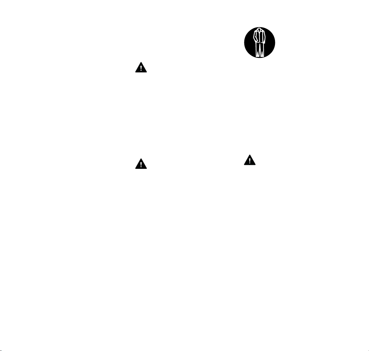
español / EE.UU
enfermedad de Raynaud, pero el clima
frío, el fumar y las enfermedades o
condiciones físicas que afectan los
vasos sanguíneos y la circulación de la
sangre, como asimismo los niveles altos
de vibración y períodos prolongados de
exposición a la vibración son
mencionados como factores en el
desarrollo de la enfermedad de
Raynaud. Por lo tanto, para reducir el
riesgo de la enfermedad de dedos
blancos y del síndrome del túnel
carpiano, sírvase notar lo siguiente:
– Las tronzadoras de STIHL se
equipan con un sistema
antivibración ("AV") diseñado para
reducir la transmisión de las
vibraciones creadas por la máquina
a las manos del operador. Se
recomienda el uso del sistema AV a
aquellas personas que utilizan
tronzadoras en forma constante y
regular.
– Use guantes y mantenga las manos
abrigadas.
– Mantenga el sistema AV en buen
estado. Una tronzadora con los
componentes flojos o con
elementos AV dañados o
desgastados también tendrá
tendencia a tener niveles más altos
de vibración.
– Agarre firmemente los mangos en
todo momento, pero no los apriete
con fuerza constante y excesiva.
Tómese descansos frecuentes.
Todas las precauciones antes
mencionadas no le garantizan que va a
estar totalmente protegido contra la
enfermedad de Raynaud o el síndrome
del túnel carpiano. Por lo tanto, los
operadores constantes y regulares
deben controlar con frecuencia el
estado de sus manos y dedos. Si
aparece alguno de los síntomas arriba
mencionados, consulte inmediatamente
al médico.
ADVERTENCIA
El sistema de encendido de la máquina
produce un campo electromagnético de
intensidad muy baja. El mismo puede
interferir con algunos tipos de
marcapasos. Para reducir el riesgo de
lesiones graves o mortales, las
personas portadoras de marcapasos
deben consultar a sus médicos y al
fabricante del marcapasos antes de
usar esta máquina.
Vestimenta adecuada
ADVERTENCIA
Para reducir el riesgo de lesiones el
operador debe usar el equipo protector
adecuado.
La ropa debe ser de
confección fuerte y ajus
tada, pero no tanto que
impida la completa liber
tad de movimiento. Evite
el uso de chaquetas suel
tas, bufandas, corbatas,
joyas, pantalones acam
panados o con vueltas,
pelo largo suelto o cual
quier cosa que pueda
engancharse en los
obstáculos o las piezas
en movimiento de la
máquina. Use monos o
pantalones largos para
protegerse las piernas.
No vista pantalones
cortos.
ADVERTENCIA
Cuando se corta metal, la máquina crea
chispas capaces de incendiar la ropa.
La mayoría de las telas usadas para
fabricar la vestimenta son inflamables aun las telas retardadoras de incendio
se encienden si la temperatura es
elevada. Para reducir el riesgo de
quemaduras, STIHL recomienda vestir
ropa de cuero, lana, algodón con
tratamiento retardador de incendio o
una tela de algodón gruesa y con tejido
apretado, tal como la tela de jeans.
Algunas telas sintéticas retardadoras de
incendio también son adecuadas, pero
otras tales como el poliéster, nilón,
rayón y acetato pueden derretirse y
formar una sustancia similar al alquitrán
que quema la piel. Lea las instrucciones
del fabricante de vestimentas.
Mantenga la ropa libre de aceite,
combustible, grasa y otras sustancias
inflamables.
-
-
-
-
-
54
TS 410, TS 420
Page 57
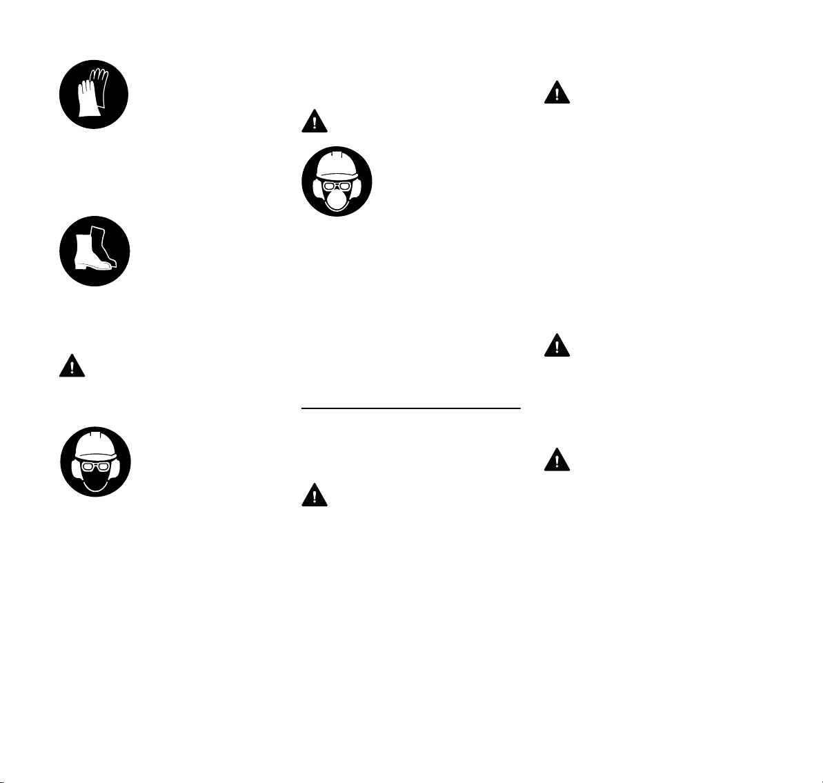
español / EE.UU
Siempre use guantes
gruesos (por ejemplo,
fabricados de cuero u
otro material resistente al
desgaste) cuando mani
pule la tronzadora. Los
guantes gruesos y anti
deslizantes mejoran el
manejo y ayudan a prote
ger las manos.
Una buena base de
apoyo es indispensable
cuando se maneja la sie
rra. Póngase botas
gruesas con suela anti
deslizante.
Recomendamos las
botas de seguridad con
puntera de acero.
ADVERTENCIA
La herramienta de corte puede lanzar
objetos sueltos hacia el operador.
Para reducir el riesgo de
lesionarse los ojos,
nunca maneje la sierra si
no tiene puestas gafas o
anteojos de seguridad
bien ajustados con una
protección adecuada en
las partes superior y late
rales que satisfagan la
norma ANSI Z87 "+". La
protección adecuada de
los ojos es indispensable.
Use un casco de seguridad
reglamentario para protegerse la
cabeza. El ruido producido por la
tronzadora puede lesionarle los oídos.
Siempre use amortiguadores del ruido
(tapones u orejeras) para protegerse los
-
-
-
oídos. Los usuarios regulares deben
someterse con frecuencia a un examen
o control auditivo.
ADVERTENCIA
Si no se está usando el
corte en mojado al caudal
-
-
LA HERRAMIENTA MOTORIZADA
Para las ilustraciones y definiciones de
las piezas de la tronzadora, vea el
capítulo "Piezas principales".
ADVERTENCIA
Nunca modifique, de ninguna manera,
-
una tronzadora. Las piezas y accesorios
marca STIHL son los únicos
expresamente aprobados por STIHL
para uso con modelos específicos de
tronzadoras STIHL. Aunque otras
piezas o accesorios pueden utilizarse
con el motor STIHL, el uso de los
mismos puede resultar ser
extremadamente peligroso.
recomendado, el opera
dor debe usar siempre un
respirador aprobado por
NIOSH/MSHA para el
material en uso, con el fin
de reducir el riesgo de
sufrir una enfermedad
respiratoria grave o mor
tal. Para más detalles y
advertencias sobre este
tema, lea la información
bajo "Condiciones de tra
bajo" en este manual de
instrucciones.
Discos abrasivos
ADVERTENCIA
Antes de montar el disco de corte,
compruebe que la velocidad máxima de
uso del disco sea mayor o igual que la
velocidad del árbol de la tronzadora
-
dada en la sección de especificaciones
de este manual. Un disco que no cumpla
con estas condiciones puede romperse
o hacerse pedazos y constituir una
amenaza de lesiones graves o mortales
al operador o a terceros.
Los discos abrasivos para cortes a
-
manos libres soportan esfuerzos de
torcedura y compresión particularmente
altos.
-
ADVERTENCIA
Nunca use un buje reductor insertado en
el disco para reducir el diámetro del
agujero de montaje. El disco puede
deslizarse, causando deslineamento,
vibraciones y rotura del disco.
ADVERTENCIA
Los discos de marca no STIHL tienen
mayor probabilidad de quebrarse o de
crear otros peligros, tales como fuerzas
de reacción mayores. Utilice
únicamente discos con capacidad de
régimen aprobada. Lea y siga las
precauciones de seguridad adicionales
dadas con el disco.
TS 410, TS 420
55
Page 58

español / EE.UU
ADVERTENCIA
Inspeccione el disco
abrasivo con frecuencia y
sustitúyalo de inmediato
si tiene roturas o comba
duras. Los discos rotos o
combados pueden rom
perse o quebrarse y
causar lesiones persona
les graves o mortales.
Los discos abrasivos
deformados o desequili
brados pueden aumentar
las vibraciones y acortar
la vida útil de la
tronzadora
Algunos discos abrasivos adiamantados
de marcas diferentes a STIHL tienen
núcleos de acero de calidad deficiente,
no están debidamente tensados o
adolecen de defectos de diseño o de
fabricación. Como resultado de ello,
pueden empezar a oscilar durante el
uso, lo cual puede causar la rotura del
disco. Esta oscilación también puede
resultar en el atascamiento del disco en
la ranura, el cual, en ciertas
condiciones, puede causar lesiones
graves o mortales debido al efecto de
las fuerzas reactivas. Vea la sección
"Fuerzas reactivas incluyendo
contragolpe." Nunca use un disco que
oscila o que ha oscilado en el pasado. A
pesar de que el disco puede dejar de
oscilar temporalmente, por ejemplo, al
hacerlo girar sin carga, siempre tendrá
una tendencia de volver a oscilar bajo
ciertas condiciones. Sustitúyalo
inmediatamente antes de volverlo a
usar.
-
-
Los discos abrasivos de material
compuesto son sensibles al calor.
Siempre guarde la tronzadora en un
lugar en el cual el disco de material
compuesto no quede expuesto a la luz
solar directa ni a otras fuentes de calor.
-
Guarde los discos de resina compuesta
de reserva colocándolos sobre una
superficie nivelada en un lugar seco,
libre del riesgo de daños por
-
congelación. El no seguir estas
instrucciones puede hacer que el disco
se rompa o se quiebre y causar lesiones
graves o incluso mortales.
ADVERTENCIA
Nunca use discos de sie
rra circular, discos con
puntas de carburo, dis
cos reconstruidos, discos
abrasivos para madera ni
discos con dientes de
tipo alguno. Pueden cau
sar lesiones personales
graves como resultado
del contacto con la hoja
de sierra o los objetos
lanzados y/o las fuerzas
reactivas, incluyendo el
contragolpe. Vea la
sección "Fuerzas reacti
vas". El concesionario
STIHL tiene un inventario
de discos abrasivos
especiales para los diver
sos usos de la
tronzadora.
ADVERTENCIA
Si se usa un modelo incorrecto de disco
abrasivo o el disco se usa con el
propósito de cortar un material para el
que no fue diseñado, el disco podría
bailar, romperse o incrementar las
fuerzas reactivas y causar lesiones
graves o mortales. Consulte la
información que se proporciona a
continuación y la sección "Fuerzas
reactivas".
Solo utilice el disco abrasivo aprobado
para el tipo de material a cortarse.
Existen diferentes tipos de discos
abrasivos, cada uno de los cuales tiene
marcas especiales. Por ejemplo, con
respecto a los discos de material
compuesto marca STIHL:
1. Piedra
-
-
-
-
-
También pueden usarse para cortar
hormigón, mampostería, hormigón
reforzado y ladrillo.
2. Acero
Puede usarse para cortar todo tipo
de metales ferrosos.
3. Asfalto
También puede usarse para cortar
hormigón con agregados.
4. Hierro dúctil
También puede usarse para cortar
ciertos tipos de hierro fundido (SG
17-24), bronce y cobre.
Para cortar materiales compuestos,
consulte con el concesionario STIHL.
Discos adiamantados abrasivos
Los discos adiamantados abrasivos
tienen un rendimiento de corte mucho
mejor que los discos abrasivos de resina
compuesta. Los discos adiamantados
tienen su parte central de acero con
partículas de diamante incrustadas en
sus filos.
56
TS 410, TS 420
Page 59

español / EE.UU
Se pueden usar para cortar hormigón,
asfalto, piedra natural, tubería de arcilla,
ladrillos y cosas por el estilo. STIHL
también ofrece discos adiamantados
para cortar hierro dúctil y algunos
aceros estructurales.
Sin embargo, estos no son adecuados
para cortar todos los metales u otros
materiales.
Es posible cortar en seco o mojado. Se
incluyen accesorios para conducir agua
para usarse con la tronzadora STIHL.
Consulte la sección correspondiente del
manual de instrucciones.
ADVERTENCIA
No vuelva a instalar un disco
adiamantado abrasivo que esté usado
sin cerciorarse primero de que no haya
muescas, planicidad, fatiga del centro,
daño o pérdida de segmentos,
evidencia de calor excesivo
(decoloración) y posible daño del
agujero para el portaherramienta. Vea el
capítulo "Discos de corte
adiamantados." Revise si el disco tiene
grietas y asegúrese de que no se haya
desprendido ningún pedazo de disco
antes de comenzar a usarlo.
Siempre instale el disco de modo que la
flecha que tiene marcada apunte en el
sentido de giro del árbol.
USO DE LA HERRAMIENTA
MOTORIZADA
Transporte de la tronzadora Cutquik de
STIHL
ADVERTENCIA
Para reducir el riesgo de lesionarse por
la activación inesperada y/o el contacto
con un disco en movimiento, siempre
apague el motor antes de colocar la
tronzadora en el suelo o acarrearla. El
disco abrasivo sigue girando por un
tiempo breve (desaceleración en rueda
libre) después que se suelta el gatillo de
aceleración (efecto de volante).
Detenga el disco poniendo el fondo del
mismo en contacto ligero con una
superficie dura o espere hasta que el
disco se pare por sí solo. El acarrear la
tronzadora con el motor funcionando es
extremadamente peligroso. La
aceleración accidental del motor puede
causar la rotación del disco. Evite tocar
el silenciador caliente.
Por mano: Cuando acarree la
tronzadora a mano, apague el motor y
colóquela en la posición correcta. Sujete
el mango delantero y coloque el
silenciador a un costado, alejado del
cuerpo con el accesorio de corte hacia
atrás.
ADVERTENCIA
Siempre evite que el disco de corte se
golpee contra el suelo o contra otros
objetos. Los discos dañados pueden
quebrarse y causar lesiones graves o
mortales.
Por vehículo: Sujete la tronzadora
debidamente para impedir que se
vuelque, derrame combustible y dañe la
tronzadora. Nunca la transporte con el
disco instalado. Un disco que se ha
dañado durante el transporte puede
quebrarse al usar la máquina y causar
lesiones personales graves.
Combustible
La herramienta motorizada STIHL utiliza
una mezcla de aceite-gasolina como
combustible (vea el capítulo
"Combustible" en el manual de
instrucciones).
ADVERTENCIA
La gasolina es un com
bustible muy inflamable.
Si se derrama y arde a
causa de una chispa u
otra fuente de ignición,
puede provocar un incen
dio y quemaduras graves
o daños a la propiedad.
Tenga sumo cuidado
cuando manipule gaso
lina o la mezcla de
combustible. No fume
cerca del combustible o
la herramienta motori
zada, ni acerque ningún
fuego o llama a ellos.
Puede escapar vapor
inflamable del sistema de
combustible.
-
-
-
-
TS 410, TS 420
57
Page 60

español / EE.UU
ADVERTENCIA
El polvo puede acumularse en el motor,
especialmente alrededor del carburador
y puede absorber gasolina, aumentando
el riesgo de un incendio. Limpie el polvo
del motor periódicamente.
Instrucciones para el llenado de
combustible
ADVERTENCIA
Cargue de combustible su herramienta
motorizada en lugares al aire libre bien
ventilados. Siempre apague el motor y
deje que se enfríe antes de llenar de
combustible. Dependiendo del
combustible utilizado, de las
condiciones climáticas y del sistema de
ventilación del depósito, es posible que
se forme vapor de gasolina a presión
dentro del depósito de combustible.
Para reducir el riesgo de quemaduras,
así como otras lesiones corporales
ocasionadas por los escapes de vapor
de gasolina y otras emanaciones, quite
la tapa de llenado de combustible de la
herramienta motorizada
cuidadosamente de modo que la
presión que se pueda haber acumulado
en el depósito se disipe lentamente.
Nunca quite la tapa de llenado de
combustible mientras el motor esté
funcionando.
Elija una superficie despejada para
llenar el depósito y aléjese 3 m (10 pies)
por lo menos del lugar en que lo haya
llenado antes de arrancar el motor.
Limpie todo el combustible derramado
antes de arrancar la máquina.
ADVERTENCIA
Compruebe que no exis
ten fugas de combustible
mientras llena el depósito
y durante el funciona
miento de la máquina. Si
detecta alguna fuga de
combustible, no arran
que el motor ni lo haga
funcionar sin antes repa
rar la fuga y limpiar el
combustible derramado.
Tenga cuidado de no
mancharse la ropa con
combustible. Si la man
cha, cámbiesela
inmediatamente.
ADVERTENCIA
Si se derrama el combustible sobre la
ropa, en particular sobre los pantalones,
es sumamente importante cambiarse de
ropa de inmediato. No dependa de la
evaporación. Pueden quedar residuos
inflamables de combustible en la ropa
después de un derrame por más tiempo
que lo esperado. Es sumamente
peligroso cortar metal con la tronzadora
cuando la ropa está húmeda o mojada
con gasolina, puesto que la ropa del
operador podría incendiarse y causar
lesiones graves o mortales.
ADVERTENCIA
Si la tapa de combustible está mal
apretada, la misma puede soltarse o
salirse y causar el derramamiento del
combustible.
-
-
-
Los diferentes modelos de sierras
pueden estar provistos de tapas de
combustible diferentes:
-
Tapa de llenado de combustible tipo
bayoneta
-
Nunca utilice herramientas para abrir ni
cerrar la tapa de llenado de combustible
tipo bayoneta, ya que esto podría
dañarla y causar fugas de combustible.
La tapa de llenado de combustible tipo
bayoneta debe cerrarse bien después
de haber abastecido el combustible.
Tapa de llenado de combustible con
roscas
Apriete la tapa de llenado
de combustible lo más
ajustado posible después
de haber abastecido la
máquina con
combustible.
Esto reduce el riesgo de que la tapa se
suelte debido a vibraciones en el motor,
lo cual causaría fugas de combustible.
ADVERTENCIA
Nunca intente abrir la tapa usando una
herramienta. Esto puede dañar la tapa y
permitir el escape de combustible.
58
TS 410, TS 420
Page 61

español / EE.UU
002BA058 KN
ADVERTENCIA
Antes de usar la máquina, asegúrese de
que la tapa de combustible esté bien
apretada y limpie el combustible
derramado. Compruebe que no existen
fugas de combustible mientras llena el
depósito y durante el funcionamiento de
la máquina. Si detecta alguna fuga de
combustible, no arranque el motor ni lo
haga funcionar sin antes reparar la fuga
y limpiar el combustible derramado.
Antes de arrancar
Para instalar el disco, siga el
procedimiento descrito en las secciones
pertinentes del manual de instrucciones.
ADVERTENCIA
Revise el sistema de combustible en
busca de fugas, especialmente las
partes visibles, por ejemplo, la tapa de
llenado, conexiones de mangueras y la
bomba de combustible manual
(únicamente para herramientas
motorizadas equipadas con una bomba
de combustible de mano). No arranque
el motor si se observan fugas o daños –
¡Riesgo de incendios! Solicite al
concesionario que repare la máquina
antes de usarla.
ADVERTENCIA
No maneje nunca una tronzadora que
esté dañada, mal ajustada o mantenida
o que no fue armada completa y
debidamente. Revise que la máquina
esté lista para usar correctamente.
Mantenga los mangos secos, limpios y
sin aceite ni combustible.
ADVERTENCIA
Antes de usar la sierra, compruebe que
sus controles (gatillo de aceleración,
bloqueo de gatillo de aceleración,
interruptor de apagado) y los
dispositivos de seguridad funcionen
debidamente, que las velocidades de
ralentí y máxima del carburador estén
debidamente ajustadas, que el disco
esté correctamente instalado y que el
protector del disco se encuentre en su
lugar y bien fijado a la máquina.
Inspeccione todos los discos
detenidamente para comprobar que su
condición sea buena antes de
instalarlos.
Ajuste el protector de
disco de modo que las
chispas, el polvo y los
materiales cortados se
desvíen en sentido
opuesto al operador y
que no alcancen objetos
inflamables en el
entorno. Consulte la
sección "Instrucciones de
funcionamiento" del
manual de instrucciones.
ADVERTENCIA
Asegúrese de que el casquillo de la
bujía esté firmemente colocado – un
casquillo suelto puede crear un arco
voltaico y encender los vapores del
combustible, provocando un incendio.
La tensión adecuada de la correa
trapezoidal nervada es importante. Para
evitar el ajuste inadecuado, ejecute los
procedimientos de tensado tal como se
describen en su manual. Siempre
compruebe que las tuercas de collar
hexagonales del brazo de fundición
estén debidamente apretadas.
Compruebe la tensión de la correa
nervada después de una hora de uso y
corríjala de ser necesario.
Arranque
ADVERTENCIA
Su tronzadora es una máquina que
debe ser manejada por solamente una
persona. No deje que otras personas se
acerquen a la tronzadora en marcha.
Ponga en marcha y maneje su
tronzadora sin ayuda de nadie. Para las
instrucciones específicas de arranque,
vea la sección correspondiente en el
manual de instrucciones.
Nunca arranque el motor por
lanzamiento de la máquina. Este
método es muy peligroso ya que es
posible perder el control de la
TS 410, TS 420
59
Page 62

español / EE.UU
tronzadora. Coloque la tronzadora
sobre suelo firme u otra superficie dura
en una zona despejada. Mantenga el
equilibrio y elija un buen punto de apoyo
para los pies. Asegúrese que el disco de
corte esté alejado de su persona y de
las demás obstrucciones y objetos,
incluyendo el suelo. Al arrancar el motor
con el acelerador en posición de
arranque, su velocidad será suficiente
para que el embrague engrane la polea
de correa y se mueva el disco. Nunca
intente arrancar la tronzadora si el disco
abrasivo está insertado en un corte.
Tan pronto arranque, accione
inmediatamente por un breve momento
el gatillo de aceleración para
desconectar el bloqueo de gatillo de
aceleración y permitir que la velocidad
del motor se reduzca al valor de ralentí.
ADVERTENCIA
Cuando tire del mango de arranque, no
enrolle la cuerda de arranque alrededor
de la mano. No deje que el mango
vuelva por sí solo a su posición original,
sino guíe lentamente la cuerda con la
mano para que se enrolle
correctamente. Si no ejecuta este
procedimiento puede lastimarse la
mano o los dedos y también dañar el
mecanismo de arranque.
Ajustes importantes
A la velocidad de ralentí correcta, el
disco no debe girar. Para instrucciones
de ajuste de la velocidad de ralentí, vea
la sección correspondiente del manual
de instrucciones.
ADVERTENCIA
No use una tronzadora que tenga la
velocidad de marcha en vacío
desajustada. El disco en movimiento
puede causar lesiones. Si no es posible
obtener el ajuste correcto, pida al
concesionario STIHL que revise la sierra
y haga los ajustes o reparaciones
necesarios.
Condiciones de trabajo
Maneje la tronzadora solamente en
condiciones de buena visibilidad y a la
luz del día.
El uso de protectores para los oídos
reduce la percepción de sonidos. Esté
atento para no perder las señales de voz
de sus compañeros de trabajo.
Manténgase a una distancia que le
permita comunicarse con otras
personas en caso de necesitar ayuda.
ADVERTENCIA
Tan pronto arranca, este
producto genera vapores
de escape tóxicos que
contienen productos
químicos (tales como
hidrocarburos sin quemar
y monóxido del carbono,
incluyendo el benceno)
considerados como cau
santes de enfermedades
respiratorias, cáncer,
defectos de nacimiento u
otra toxicidad reproduc
tora. Algunos de estos
gases (por ej., monóxido
de carbono) pueden ser
incoloros e inodoros.
Para reducir el riesgo de
sufrir lesiones graves o
mortales por respirar
gases tóxicos, nunca
haga funcionar la
máquina puertas adentro
o en lugares mal ventila
dos. Asegúrese de tener
ventilación adecuada
cuando trabaje en zanjas
u otros lugares
confinados.
ADVERTENCIA
El uso de este producto para cortar
mampostería, hormigón, metal y otros
materiales puede generar polvo o
vapores que contienen productos
químicos conocidos como causantes de
lesiones graves o mortales o
enfermedades como trastornos
respiratorios, cáncer, defectos de
nacimiento u otro daño a los órganos
reproductores. Si usted desconoce los
-
-
-
60
TS 410, TS 420
Page 63

español / EE.UU
riesgos relacionados con el material en
cuestión, lea la hoja de datos de
seguridad del material y/o consulte con
su empleador, el fabricante/proveedor
del material, organismos
gubernamentales tales como OSHA y
NIOSH y otras fuentes de información
sobre los materiales peligrosos. Por
ejemplo, el Estado de California y
algunas otras autoridades han
publicado varias listas de sustancias
carcinógenas, de toxicidad
reproductora, etc. Siempre que sea
posible, trate de controlar el polvo y los
vapores en su punto de origen.
Al respecto, emplee buenas prácticas
de trabajo y siga las recomendaciones
del fabricante/proveedor, OSHA/NIOSH
y asociaciones laborales y comerciales.
Se proporciona un juego de accesorio
de agua con la tronzadora, el cual debe
usarse para suprimir el polvo cuando el
corte en mojado es factible. Para
suprimir el polvo, el caudal debe ser de
por lo menos 0,6 litros (20 oz. fl.) de
agua por minuto. Cuando no se efectúa
el corte mojado al caudal recomendado,
el operador y cualquier persona que se
encuentre cerca siempre deben usar un
respirador aprobado por NIOSH/MSHA
para el material en uso. Consulte la
sección de "Protección para las vías
respiratorias", en el capítulo "Ejemplos
de usos" del manual de instrucciones.
Incluso si está empleando técnicas de
corte mojado al caudal recomendado,
un operador cortando por más de dos
horas al día debe usar por lo menos un
respirador desechable del tipo aprobado
por NIOSH. Consulte y aténgase a las
leyes o reglamentos federales, estatales
o locales referentes al corte en seco y
corte mojado.
ADVERTENCIA
Al cortar mampostería, hormigón y otros
materiales que contienen sílice en su
composición, se puede despedir polvo
con contenido de sílice cristalina. La
sílice es un componente básico de la
arena, cuarzo, arcilla de ladrillo, granito
y numerosos minerales y rocas. La
inhalación repetida y/o sustancial de la
sílice cristalina en suspensión en el aire
puede causar una enfermedad
respiratoria grave o mortal, incluida la
silicosis. Además, el estado de
California y algunas otras autoridades
han colocado a la sílice cristalina en la
lista de sustancias carcinógenas.
Cuando corte tales materiales, siempre
tome las medidas de precaución
respiratorias antes mencionadas.
ADVERTENCIA
La aspiración del polvo de asbesto es
peligrosa y puede causar lesiones
graves o mortales, enfermedades de las
vías respiratorias o cáncer. El uso y la
eliminación de los productos que
contienen asbesto están estrictamente
reglamentados por OSHA y el
Organismo para la Protección del Medio
Ambiente (EPA) de los EE.UU. No use
la tronzadora para cortar o remover
asbesto, productos que contengan
asbesto u otros productos tales como
tubería envuelta o cubierta con aislante
de asbesto. Si por cualquier motivo cree
que está cortando asbesto, póngase en
contacto inmediatamente con su
empleador o un representante de OSHA
local.
002BA549 AM
ADVERTENCIA
La tronzadora STIHL ha sido diseñada
para usarse con las manos o con un
carro para tronzadoras. Si se hacen
cortes con la v apoyada sobre el suelo u
otra superficie, se puede causar el
desgaste excesivo de la escuadra que
protege la parte inferior de la caja del
tanque. Se puede causar la pérdida de
combustible y lesiones personales.
Sustituya las escuadras dañadas o muy
desgastadas de inmediato.
Agarre de la sierra: Nunca use la
tronzadora con una sola mano. Siempre
sujete la tronzadora firmemente con
ambas manos mientras el motor está
funcionando. Coloque la mano izquierda
sobre el mango delantero y la derecha
sobre el mango trasero y el gatillo de
aceleración. Las personas que trabajan
con la mano izquierda (zurdos) también
deben seguir estas instrucciones.
Cierre firmemente los dedos alrededor
de los mangos, manteniéndolos bien
apoyados entre el pulgar y dedo índice.
Asegúrese que los mangos de la
tronzadora y el mango de arranque
están en buenas condiciones y sin
humedad, resina, aceite, mezcla de
combustible o grasa.
TS 410, TS 420
61
Page 64
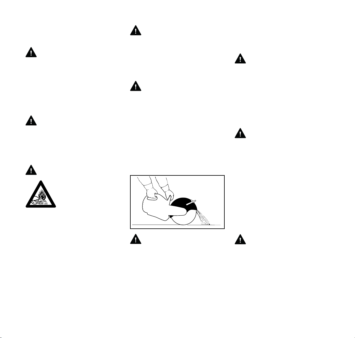
español / EE.UU
002BA550 AM
No toque nunca con las manos o
cualquier parte del cuerpo un disco que
está girando.
ADVERTENCIA
Despeje la zona donde está trabajando.
Evite tropezar con obstáculos y esté
atento a los agujeros o zanjas. Sea
sumamente precavido cuando trabaje
en declives o terreno irregular. Proceda
con sumo cuidado cuando trabaje en
condiciones climáticas húmedas o frías
(lluvia, nieve, hielo).
ADVERTENCIA
Nunca use la sierra con el bloqueo de
arranque del acelerador aplicado,
puesto que ello no permite controlar la
velocidad del motor y puede causar
lesiones graves.
ADVERTENCIA
Las chispas emitidas al
cortar metal pueden cau
sar quemaduras o
incendiar la ropa. Siem
-
pre dirija las chispas en
sentido opuesto al opera
dor y a sustancias
inflamables en el
entorno. Nunca corte
metales mientras está
parado en una superficie
inflamable, tal como las
superficies de madera o
papel alquitranado. Si
existe el riesgo de que se
produzca un incendio,
tenga equipo extinguidor
de incendios a mano.
ADVERTENCIA
Para reducir el riesgo de lesionarse
debido a un incendio, no corte ningún
tubo, tambor ni otro tipo de envase sin
antes verificar que el mismo no
contenga sustancias volátiles o
inflamables.
ADVERTENCIA
Cuando se cortan paredes y pisos
existentes o estructuras similares, esté
atento a peligros ocultos tales como
cables eléctricos, tuberías de agua o de
gas y sustancias inflamables.
Compruebe que los servicios de energía
eléctrica, agua y gas hayan sido
interrumpidos y que se hayan vaciado
todos los tubos antes de empezar a
cortar.
Instrucciones de manejo
-
-
ADVERTENCIA
El protector del disco puede ajustarse.
Es sumamente importante que el
protector del disco se encuentre en su
lugar y ajustado según el tipo de trabajo
a efectuar y la posición. El protector
siempre debe ajustarse de modo que el
usuario no esté expuesto a los peligros
causados por las partículas lanzadas ya
sea directa o indirectamente del material
cortado, las chispas o los pedazos de
discos dañados. El no seguir estas
instrucciones puede causar lesiones
graves o mortales.
ADVERTENCIA
Su tronzadora está equipada con un
tope limitador para el protector del disco
que limita la abertura del protector del
disco. Para reducir el riesgo de lesiones
como resultado del contacto con el disco
y/o las fuerzas reactivas y para evitar
dañar el sistema de protección, nunca
intente desplazar la palanca de ajuste
más allá del tope limitador.
ADVERTENCIA
Siempre revise el disco antes de usarlo
y después de haber chocado
accidentalmente con algún objeto.
Revíselo frecuentemente durante el
uso, luego de haberlo detenido. Busque
grietas y verifique que esté libre de
daños, en buenas condiciones, y que
ninguna de sus piezas se haya roto. Vea
las secciones sobre "Discos abrasivos"
y "Fuerzas reactivas" en este manual.
Busque roturas en el protector del disco.
Si se descubren roturas o grietas,
instale un protector nuevo antes de
seguir usando la máquina.
ADVERTENCIA
Es esencial determinar el sentido del
corte con precisión antes de aplicar el
disco abrasivo al material a ser cortado.
Los discos se fabrican para soportar
presión en sentido radial solamente.
Evite la presión lateral. Sostenga la
tronzadora de modo constante. Para
reducir el riesgo de sufrir lesiones
graves o mortales, no cambie el sentido
62
TS 410, TS 420
Page 65

español / EE.UU
de avance del corte al hacerlo ya que
esto puede imponer una carga torsional
grande sobre el disco abrasivo y
quebrarlo o romperlo. Un disco
atascado también puede producir
fuerzas reactivas. Vea la sección
"Fuerzas reactivas".
ADVERTENCIA
No use los discos abrasivos para limar.
En estos trabajos se producen fuerzas
de flexión que pueden resultar en la
rotura de los discos abrasivos con la
posibilidad de lesiones graves o
mortales.
ADVERTENCIA
Para reducir el riesgo de lesiones
causadas por discos abrasivos rotos:
1. No exceda la velocidad máxima de
funcionamiento indicada en el
disco.
2. No use un disco que haya caído al
suelo.
3. Pruebe cada disco nuevo
inmediatamente después de
haberlo instalado haciéndolo
funcionar a velocidad máxima por
aproximadamente un minuto sin
cortar, cerciorándose que las
demás personas presentes se
encuentren alejadas.
4. No corte ningún material para el
cual el disco abrasivo no está
diseñado o aprobado.
5. No esmerile aplicando el disco
abrasivo de costado.
6. No tuerza, empuje, golpee ni deje
caer la máquina. Eso puede dañar
el disco.
Para obtener un corte limpio y eficaz,
tire del disco abrasivo sobre la superficie
trabajada o muévalo en uno y otro
sentido de la dirección de corte. No
aplique fuerza para meter el disco
abrasivo en la superficie trabajada.
Inserte el disco en el material
únicamente a la profundidad necesaria
para hacer el corte. Para reducir la
cantidad de polvo, no corte los
materiales de piedra y hormigón
completamente. Deje una franja
delgada sin cortar. En la mayoría de
estos tipos de materiales, esta franja
puede romperse con facilidad después.
No tuerza, trabe o esfuerce el disco en
el corte.
Siempre apague el motor y compruebe
que el disco haya dejado de girar antes
de poner la tronzadora en el suelo.
Si se usa un carro para tronzadoras,
quite la basura de la trayectoria de las
ruedas, ya que la misma puede causar
la flexión del disco abrasivo. Esto puede
causar fuerzas grandes de fricción y
reducir significativamente la potencia
del motor disponible para la tarea de
corte. También puede dañar el disco
abrasivo.
STIHL recomienda el uso de un carro
para efectuar cortes largos en línea
recta.
Corte en mojado con discos abrasivos
Antes de cortar en mojado, verifique que
el agua no vaya a dañar el piso o el
edificio.
ADVERTENCIA
Para reducir el riesgo de electrocución
para usted u otras personas, no deje
que el agua o lodo quede en contacto
los alambres eléctricos con corriente.
ADVERTENCIA
Para reducir el riesgo de lesiones
causadas por la rotura del disco al cortar
en mojado con un disco de material
compuesto:
1. Compruebe que el agua no fluya
sobre un disco que no esté en
marcha, ya que el disco absorbe el
agua, lo cual altera su equilibrio.
2. Asegúrese de aplicar agua a ambos
lados del disco, ya que la
distribución desigual puede causar
el desgaste desigual del disco.
3. Al terminar el trabajo, haga
funcionar el disco de corte a la
velocidad de funcionamiento
normal durante 3 a 6 segundos sin
agua para quitar el agua residual.
ADVERTENCIA
Para reducir la posibilidad de lesiones
causadas por la rotura de un disco de
material no diseñado específicamente
para el corte en mojado, nunca guarde y
vuelva a usar un disco de este tipo que
ha sido empleado con agua. Use estos
discos hasta agotarlos en un mismo día.
TS 410, TS 420
63
Page 66
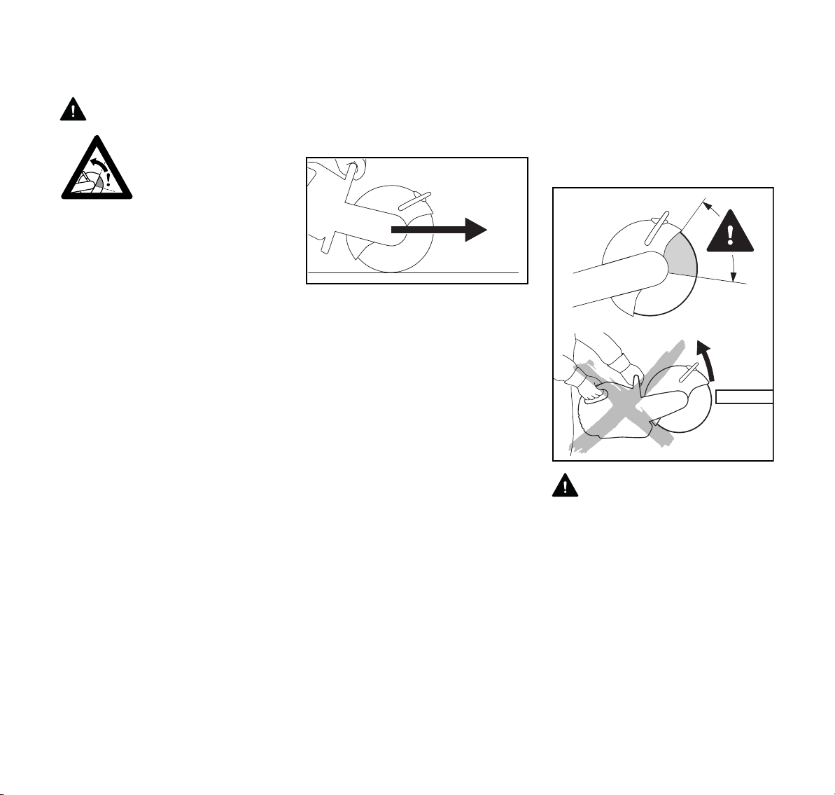
español / EE.UU
Fuerzas reactivas, incluido el
contragolpe
ADVERTENCIA
Las fuerzas reactivas
pueden producirse en
cualquier momento que
el disco de la tronzadora
esté girando.
La gran fuerza utilizada para cortar el
material puede cambiar de sentido y
actuar contra el operador. Si el disco
reduce su velocidad o se detiene como
resultado del contacto con un objeto
macizo o de la estricción o el
aprisionamiento, las fuerzas reactivas
pueden producirse instantáneamente, y
pueden hacer que el operador pierda el
control de la tronzadora y resultar en
lesiones graves o mortales.
Una buena comprensión de las causas
de estas fuerzas reactivas puede
ayudarle a evitar la pérdida del control.
Las fuerzas reactivas se aplican en
sentido opuesto al del movimiento del
disco en el punto de contacto o de
estricción/aprisionamiento. Si el disco
reduce su velocidad solamente como
resultado del contacto con un objeto
macizo, tal como la pieza de trabajo, las
fuerzas reactivas resultantes
normalmente son moderadas y el
operador que está agarrando
correctamente la máquina puede
mantener el control de la misma. Pero,
si el disco reduce su velocidad o se
detiene como resultado de una
estricción o un aprisionamiento severo,
las fuerzas reactivas pueden ser
sustancialmente más grandes. Cuanto
mayor sea la fuerza generada, tanto
más difícil será para el operador
controlar la tronzadora. La pérdida de
control puede resultar en lesiones
personales graves o la muerte.
Fuerzas de culatazo, trepado, estricción
y contragolpe rotacional
Las fuerzas reactivas más comunes son
los culatazos y el trepado. Si el contacto
se produce en la parte inferior del disco,
la tronzadora intentará alejarse del
operador (culatazo). Si el contacto se
produce en el extremo delantero del
disco, éste puede intentar "trepar" sobre
el objeto cortado (trepado).
La estricción ocurre cuando la pieza que
se está cortando se cierra contra el
disco. Las fuerzas laterales aplicadas al
disco en la ranura o un disco
adiamantado incorrecto o dañado que
empieza a oscilar o deja de hacerlo en la
ranura pueden causar el
aprisionamiento severo. Si el cuadrante
superior del disco sufre una estricción o
un aprisionamiento severo o se atasca,
puede ser lanzado instantáneamente
hacia arriba y hacia atrás, hacia el
operador, con mucha fuerza y en
sentido giratorio. Es posible evitar estas
condiciones de contragolpe y siempre
se debe hacerlo. Es posible evitar la
estricción del disco al apoyar
correctamente la pieza de trabajo. (Vea
más abajo.) Es posible evitar el
aprisionamiento severo del disco al
emplear las técnicas correctas de corte,
tales como el no aplicar cargas laterales
en el disco y el usar los discos que han
sido correctamente diseñados,
fabricados y mantenidos.
Para reducir el riesgo de lesiones por
contragolpes
002BA553 AM
002BA582 ST
ADVERTENCIA
Para reducir el riesgo de lesionarse por
un contragolpe, evite cortar con el
cuadrante superior del disco, siempre
que sea posible. Tenga cuidado
particular de no aprisionar el disco en
esta zona, lo cual puede causar fuerzas
reactivas severas con un efecto de
contragolpe giratorio.
64
TS 410, TS 420
Page 67
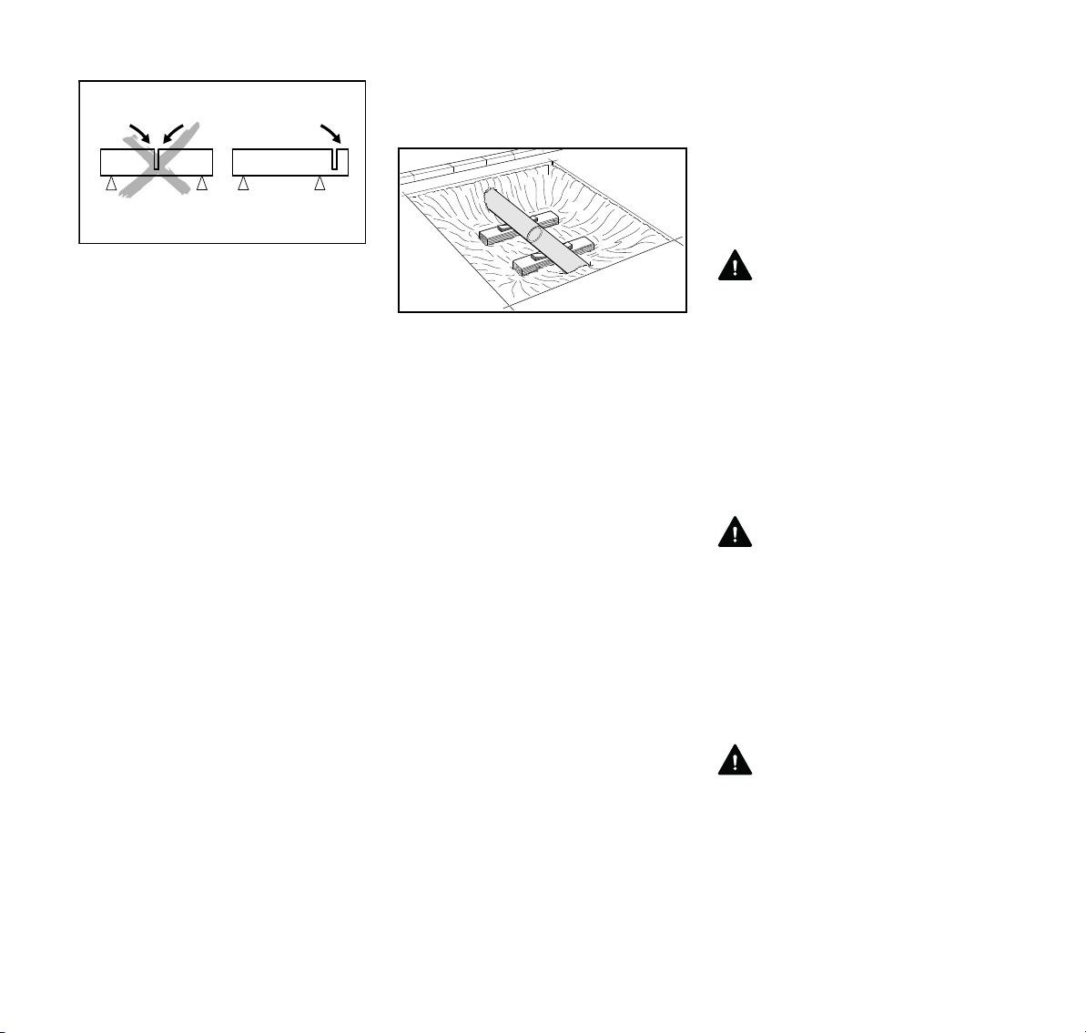
español / EE.UU
002BA146 KN
002BA603 KN
Evite el atascamiento. La pieza cortada
no debe atascar el disco abrasivo.
Esté alerta al movimiento potencial del
material que se está cortando o a
cualquier otra condición que pueda
causar el cierre del corte y la estricción
del disco. Para reducir el riesgo de
estricción, sujete el material de tal
manera que el corte permanezca abierto
durante la operación y al finalizar el
proceso (vea la ilustración). Nunca haga
un corte que cause el atascamiento del
disco. Si no es posible apoyar
correctamente el material, no utilice la
tronzadora para hacer el corte;
seleccione otra herramienta u otra
técnica de corte que no involucra el
riesgo de contragolpe.
Ante la posibilidad de que se produzca
una estricción, puede dejar una pieza
sin cortar, que impida el cierre de la
ranura de corte y la estricción del disco,
para luego cortarla manualmente. Al
realizar un corte completo, asegúrese
de que el final del corte (y la
consiguiente separación) se efectúe en
la parte superior del material, con la
parte inferior del disco. De esta forma,
cualquier estricción residual se
producirá en la parte inferior del disco,
donde podría originarse un culatazo,
pero no un contragolpe. Esté atento al
culatazo.
Los objetos que se cortarán deben estar
bien sujetos y fijos para que no rueden,
resbalen ni vibren.
Coloque un soporte para los tubos
descubiertos en una zanja, de manera
de que queden estables y puedan
sostener peso. Si los extremos de un
tubo están firmemente apoyados en el
suelo, este puede servir de apoyo en el
punto donde el tubo sale al exterior. No
obstante, será necesario utilizar un
soporte adicional cerca del corte para
evitar la combadura (vea la ilustración).
Esté atento a los tubos que se
encuentren bajo tensión y puedan
moverse durante el corte. Un tubo
colocado en el suelo puede estar en
tensión si la superficie es irregular.
Asegúrese de que todas las secciones
del tubo que se retirarán estén
correctamente sujetas y no puedan
moverse. Es posible que, después del
primer corte, deba mover los soportes o
agregar soportes adicionales para el
segundo corte, a fin de que ambos
lados, e incluso la sección que se
retirará, queden perfectamente
sostenidos. Esa sección también se
puede sostener desde arriba con una
correa suspendida, por ejemplo, de una
retroexcavadora. La sección deberá
estar sostenida de manera uniforme y lo
suficientemente tensa para que
permanezca en su posición y no tienda
a moverse hacia arriba o hacia abajo
como un conjunto o hacia un lado al
separarla.
Siempre preste atención en las zonas
de trabajo que se encuentren por debajo
del nivel del suelo, ya que el material de
soporte puede desmoronarse o
resbalarse.
ADVERTENCIA
Trabaje con especial cuidado al cortar
objetos como los tubos que poseen un
extremo abocinado o un tubo en una
zanja que, al no estar bien sostenido,
pueda combarse cuando se termine el
corte y atrapar el disco en la parte
superior del material que está cortando
o cerca de esta, y no en el lugar del
corte. Si la estricción se produce en el
cuadrante superior del disco abrasivo,
se puede producir un contragolpe.
ADVERTENCIA
Siempre que sea posible, use la técnica
de corte en mojado, ya que el agua
puede servir como un lubricante en las
zonas donde hay riesgo de estricción y
podría reducir la posibilidad de generar
fuerza reactivas. Si efectivamente se
producen tales fuerzas, se reducirá el
efecto de las mismas y será más fácil
mantener el control de la máquina.
ADVERTENCIA
Se recomienda usar únicamente
accesorios de corte marca STIHL. El
uso de discos de marcas diferentes a
STIHL puede ser extremadamente
peligroso. Por ejemplo, en el mercado
es posible obtener muchos discos
adiamantados de calidad inferior al nivel
TS 410, TS 420
65
Page 68
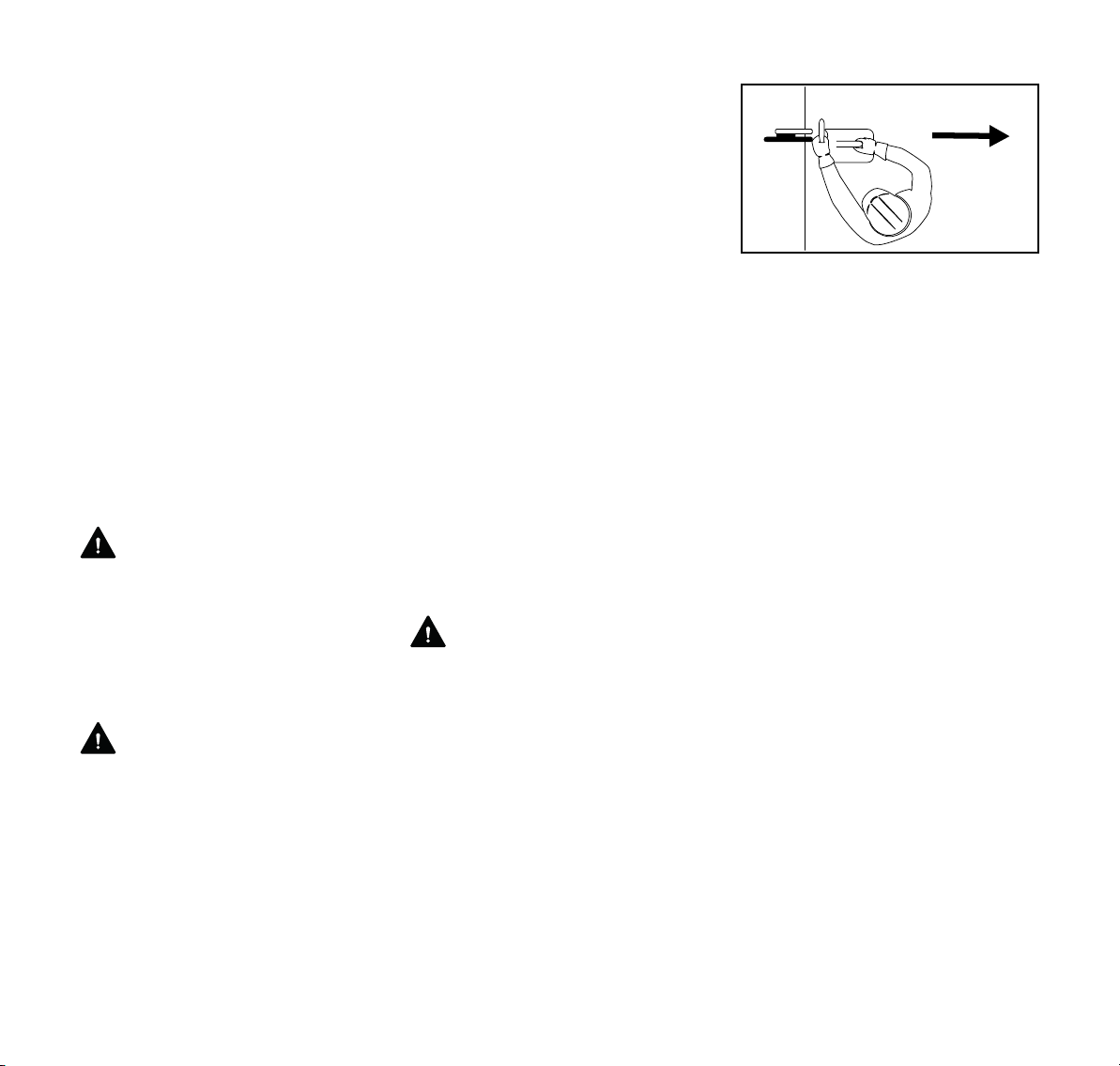
español / EE.UU
normal. Si no se fabrican con núcleos de
acero de calidad adecuada, si no están
debidamente tensados, o si adolecen de
otros defectos de diseño o fabricación,
podrían, por ejemplo, oscilar durante el
uso, perder algunos de sus segmentos,
o mostrar otros problemas que
aumentan significativamente el riesgo
de lesiones personales o mortales. Si un
disco adiamantado empieza a oscilar o
deja de hacerlo en la ranura de corte, el
cambio de comportamiento puede
resultar en el aprisionamiento severo y
la pérdida de control y/o contragolpe. Si
el disco que está usando empieza a
oscilar o lo ha hecho en el pasado,
deséchelo inmediatamente. A pesar de
que este disco puede dejar de oscilar
temporalmente, por ejemplo, al hacerlo
girar sin carga, siempre tendrá una
tendencia de volver a oscilar bajo ciertas
condiciones.
ADVERTENCIA
Algunos de los discos adiamantados de
marcas diferentes a STIHL se fabrican
con material abrasivo en los costados.
No utilice estos discos, ya que el
material abrasivo puede aumentar las
fuerzas reactivas en una situación de
estricción o de carga lateral.
ADVERTENCIA
Nunca use con la tronzadora los discos
abrasivos picados o discos de sierra
circulares, discos con puntas de
carburo, discos de rescate, ni discos
para madera o con dientes de tipo
alguno. El uso de tales discos aumenta
significativamente el riesgo de la
pérdida del control y de sufrir lesiones
personales graves o mortales como
resultado de las fuerzas reactivas,
puesto que la porción picada de un
disco abrasivo, o los dientes de un disco
de tronzadora circular pueden encajarse
en el material cortado y generar fuerzas
reactivas considerablemente más
intensas, incluso un contragolpe en
sentido giratorio.
Las tronzadoras han sido diseñadas
para usarse con discos abrasivos en
buenas condiciones solamente. Las
máquinas diseñadas para usar discos
abrasivos para madera y otros tipos de
discos con dientes utilizan sistemas
protectores diferentes que brindan la
protección necesaria para tales tipos de
discos. Las máquinas, tales como una
tronzadora, que se han diseñado para
usar discos abrasivos requieren un
sistema protector diferente, que no
ofrece protección contra todos los
peligros presentados por los discos de
sierra circular, los discos con puntas de
carburo, los discos para rescate o los
discos abrasivos para madera o con
dientes.
ADVERTENCIA
Para reducir el riesgo de lesionarse por
la pérdida del control causada por las
fuerzas reactivas, incluso el
contragolpe:
1. Sujete firmemente la máquina de
corte con ambas manos.
2. Mantenga los pies bien apoyados y
equilibrados en todo momento. No
corte nunca mientras está parado
en una escalera.
002BA554 AM
3. Coloque la tronzadora en tal
posición que su cuerpo quede
alejado del accesorio de corte. Evite
pararse en línea directa con el
disco. (Vea la ilustración.) No se
incline por encima del accesorio de
corte, especialmente cuando el
protector está deslizado hacia la
parte superior y existe riesgo de que
ocurran fuerzas reactivas.
Asegúrese de tener suficiente
libertad de movimiento,
especialmente en zanjas.
Cerciórese de que haya suficiente
espacio para el operador y para la
caída de la pieza cortada.
4. No corte a una altura superior a la
de los hombros.
5. Se recomienda el uso exclusivo de
los discos adiamantados y discos
abrasivos de material compuesto
de marca STIHL. El uso de discos
de marcas diferentes a STIHL
puede ser extremadamente
peligroso. Nunca trabaje con un
disco adiamantado que oscila, que
ha oscilado nunca o que se fabricó
con material abrasivo en sus
costados.
6. No corte madera ni ningún material
para el cual el disco abrasivo no
está diseñado o aprobado.
66
TS 410, TS 420
Page 69
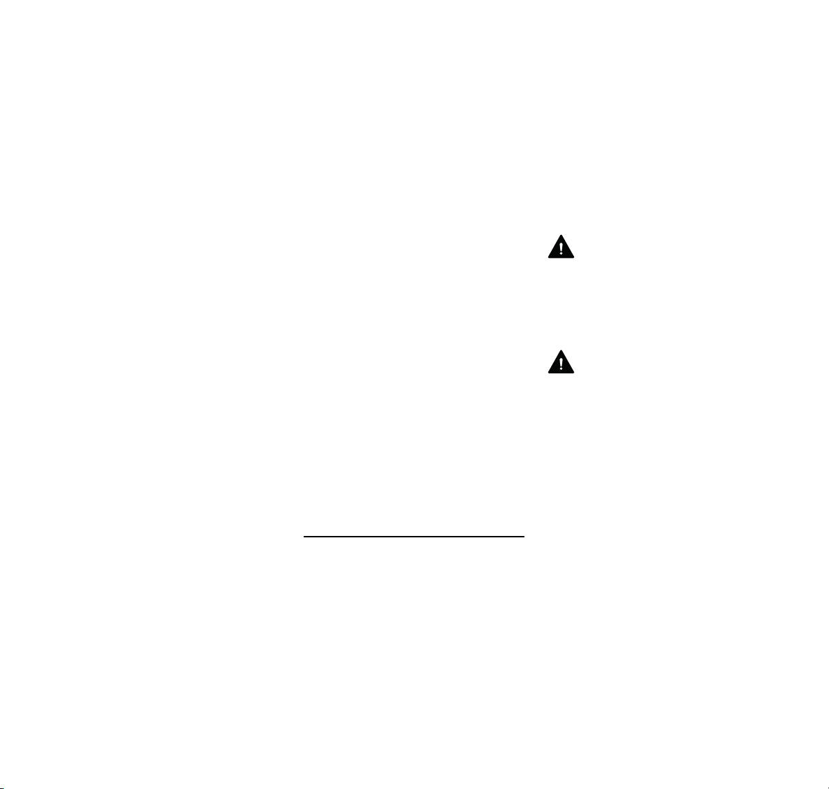
español / EE.UU
7. Nunca use discos de sierra circular,
discos con puntas de carburo,
discos reconstruidos, discos
abrasivos para madera ni discos
con dientes de tipo alguno. El
usarlos aumenta el riesgo de las
lesiones producidas por el contacto
con el disco, partículas lanzadas y
fuerzas reactivas, incluso el
contragolpe.
8. Empiece a cortar y continúe
trabajando a máxima aceleración.
9. No trate de alcanzar más lejos de lo
debido.
10. Nunca aplique una carga lateral al
disco en la ranura.
11. Use su tronzadora para cortar
solamente. No está diseñada para
usarla como una pala o barreta para
quitar objetos del paso.
12. Esté especialmente alerta a las
fuerzas reactivas, incluso el
contragolpe, cuando esté cortando
con el cuadrante superior del disco.
Nunca tire de la parte superior del
protector del disco más allá del tope
limitador.
13. Esté alerta al desplazamiento de la
pieza de trabajo o a otras fuerzas
que puedan causar el cierre del
corte y el aprisionamiento del disco,
especialmente en su cuadrante
superior. Sostenga la pieza de
trabajo de manera que el corte
permanezca abierto. Nunca haga
un corte que cause el atascamiento
del disco.
14. Utilice técnicas de corte mojado de
ser posible. En una situación de
aprisionamiento, el agua puede
actuar como lubricante y reducir la
energía de las fuerzas reactivas.
15. Deje de ejercer presión sobre la
máquina de corte cuando llegue al
extremo del corte. Demasiada
presión puede hacer que el
operador pierda control de la
máquina cuando el disco abrasivo
termina el corte. El disco abrasivo
puede hacer contacto con el
operador o chocar con algún objeto
extraño y romperse en pedazos.
16. Tenga mucho cuidado cuando
vuelva a entrar a un corte y no haga
girar el disco en un ángulo ni
empuje el disco contra el corte pues
podría quedar aprisionado.
Fuerzas giroscópicas
Esté alerta a las fuerzas giroscópicas
creadas por la rotación rápida del disco
de corte. Estas fuerzas se oponen a los
cambios de sentido, por ejemplo cuando
el operador intenta mover la máquina
lateralmente.
Mantenimiento, reparación y
almacenamiento de la tronzadora
Los trabajos de mantenimiento,
reemplazo o reparación de los
dispositivos y sistemas de control de
emisiones de escape pueden ser
realizados por cualquier taller o técnico
de motores no diseñados para
vehículos. Sin embargo, si usted está
reclamando cobertura de garantía para
algún componente que no ha sido
reparado o mantenido debidamente, o
cuando se utilizan repuestos no
autorizados, STIHL puede denegar la
garantía.
No maneje nunca una tronzadora que
esté dañada, que no haya sido bien
ajustada o que no se haya armado
completa o debidamente. Siga las
instrucciones de mantenimiento y
reparación dadas en las secciones
correspondientes del manual de
instrucciones.
ADVERTENCIA
Utilice solamente piezas de repuesto de
STIHL para el mantenimiento y
reparación. La utilización de piezas
fabricadas por otras empresas puede
causar lesiones graves o mortales.
ADVERTENCIA
Siempre apague la máquina y
asegúrese de que el disco esté detenido
antes de efectuar algún trabajo de
mantenimiento, reparación o limpieza
en la tronzadora. No intente hacer
ningún trabajo de mantenimiento o
reparación que no esté descrito en su
manual de instrucciones. Este tipo de
trabajo debe realizarse únicamente por
un concesionario de STIHL autorizado
para servicio.
Limpie el polvo producido una vez
acabado el trabajo. Apriete todas las
tuercas, pernos y tornillos, excepto los
tornillos de ajuste del carburador,
después de cada uso.
No limpie la máquina con una lavadora
a presión. El chorro fuerte de agua
puede dañar las piezas de la máquina.
TS 410, TS 420
67
Page 70

español / EE.UU
ADVERTENCIA
No pruebe nunca el sistema de
encendido con el casquillo
desconectado de la bujía, o sin tener
enroscada la bujía, ya que las chispas al
descubierto pueden causar un incendio.
ADVERTENCIA
Para reducir el riesgo de incendio y de
quemaduras, utilice solamente las
bujías autorizadas por STIHL. Siempre
inserte el casquillo de la bujía bien
apretado en el borne de la bujía del
tamaño adecuado. (Nota: Si el borne
tiene una tuerca adaptadora SAE
desmontable, tiene que ser instalada.)
Una conexión suelta entre el borne de la
bujía y el conector del cable de
encendido en el manguito puede crear
un arco voltaico y encender los vapores
del combustible y provocar un incendio.
Mantenga la bujía limpia, y asegúrese
que el conductor de encendido esté en
buen estado.
ADVERTENCIA
No maneje nunca la tronzadora si el
silenciador está dañado, se ha perdido o
fue modificado. Un silenciador mal
cuidado aumenta el riesgo de incendio y
puede causar pérdida de audición.
Nunca toque el silenciador cuando está
caliente ni le vierta combustible u otros
líquidos inflamables. Esto puede causar
quemaduras o incendios. Si el
silenciador está equipado con un
chispero para reducir el riesgo de
incendio (por ejemplo, en EE.UU.,
Canadá y Australia), no maneje nunca
su tronzadora si le falta el chispero o si
el mismo está dañado.
En California, constituiría una violación
de los acápites § 4442 o § 4443 del
Código de Recursos Públicos el uso de
herramientas con motor de gasolina en
tierras cubiertas por bosques, arbustos
o pastos, a menos que el sistema de
escape del motor cuente con un
chispero que satisfaga los requisitos
legales y reciba un mantenimiento
adecuado para estar en buenas
condiciones de funcionamiento. El
propietario/operador de este producto
es responsable del mantenimiento
adecuado del chispero. Otras
entidades/agencias estatales o
gubernamentales, tales como el
Servicio Forestal de los EE.UU., pueden
tener requisitos similares. Comuníquese
con el cuerpo de bomberos de su
localidad o con el servicio forestal para
informarse en cuanto a las leyes y
reglamentos relacionados con los
requisitos de protección contra
incendios.
Para todo trabajo de mantenimiento,
sírvase consultar la tabla de
mantenimiento y la declaración de
garantía que se encuentra al final del
manual de instrucciones.
Almacene los discos sobre una
superficie plana y en un lugar seco,
preferiblemente a una temperatura
constante, en donde no exista el riesgo
de congelación. No guarde la
tronzadora con un disco montado.
Guárdela en un lugar elevado o bajo
llave, fuera del alcance de los niños.
Vacíe el tanque de combustible antes de
guardar la máquina por un lapso de más
de unos cuantos días. Guarde el
combustible únicamente en envases
debidamente rotulados y aprobados
para ello. Evite el contacto directo del
combustible con la piel y no inhale sus
vapores.
68
TS 410, TS 420
Page 71
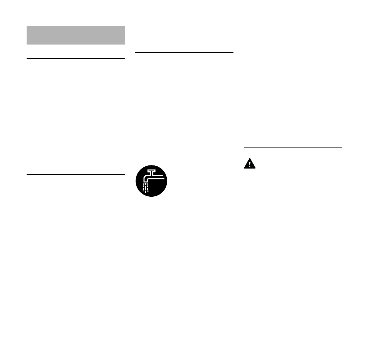
español / EE.UU
Ejemplos de usos
Conexión del agua
– La máquina tiene un juego de
conexión de agua que permite
utilizar todo tipo de suministros de
agua.
– STIHL ofrece un tanque de agua
presurizado con una capacidad de
10 litros (2,6 galones) para cortes
en mojado.
– También se ofrece un tanque de
agua que se monta en el carro
Cutquik para cortes en mojado.
La mayoría de los discos de corte
adiamantados son adecuados para el
corte en mojado.
Siempre que sea posible, utilice
técnicas de corte en mojado. Esto
prolonga la vida útil y la velocidad de
corte de los discos adiamantados.
Compruebe que el disco de corte tenga
un suministro abundante de agua.
El corte en mojado ayuda a suprimir el
polvo.
El agua captura el polvo.
El disco de corte requiere un suministro
de por lo menos 0,6 litros (20 oz. fl.) de
agua por minuto.
El corte en mojado puede reducir la
energía de las fuerzas reactivas. En
caso de un aprisionamiento, el agua
puede actuar como lubricante.
Los discos de resina compuesta pueden
usarse para el corte en seco de metales
o el corte en seco o en mojado de
hormigón, piedra o mampostería.
Discos de resina compuesta diseñados
para el corte en seco
Es necesario usar procedimientos
especiales para el corte mojado con un
disco no adiamantado de material
compuesto diseñado para el corte en
seco. Vea la sección titulada "Corte
mojado con discos abrasivos" en las
medidas de seguridad de este manual.
El corte en mojado generalmente no es
adecuado para cortar metales.
Discos de resina compuesta diseñados
para el corte mojado
Ajuste el caudal de agua
de modo que pueda aglu
tinar todo el polvo
producido (al menos
0,6 l/min [20 oz. fl./min]).
Un caudal de agua excesivo puede
hacer que el disco roce la superficie del
agua, reduciendo significativamente la
capacidad de corte. Para evitar esto, no
exceda un caudal de agua de
aproximadamente 4 l/min
(135 oz. fl./min).
Utilice el agua correctamente:
1. Asegúrese de aplicar agua a ambos
lados del disco, ya que la
distribución desigual puede causar
el desgaste desigual del disco y
posiblemente hasta su rotura.
2. Compruebe que el agua no fluya
sobre un disco que no esté en
marcha, ya que el disco absorbe el
agua, lo cual altera su equilibrio.
3. Al terminar el trabajo, haga
funcionar el disco de corte a la
velocidad de funcionamiento
normal durante 3 a 6 segundos sin
agua para quitar el agua residual.
Protección para las vías respiratorias
ADVERTENCIA
-
Cuando no se efectúa el corte mojado al
caudal recomendado, el operador y
cualquier persona que se encuentre
cerca siempre deben usar un respirador
aprobado por NIOSH / MSHA para el
material en uso. Incluso si está
empleando técnicas de corte mojado, un
operador cortando por más de dos
horas al día debe usar por lo menos un
respirador desechable del tipo aprobado
por NIOSH.
TS 410, TS 420
69
Page 72

español / EE.UU
180BA028 AM
Puntos que deben tomarse en cuenta al
usar discos de corte adiamantados y de
resina compuesta
El objeto a cortarse
– Debe estar completamente
apoyado
– Debe estar asegurado de modo que
no pueda rodar ni deslizarse
– Debe estar protegido contra las
vibraciones
La secuencia de corte
La secuencia de corte es importante
cuando se trabaja con aberturas y
recovecos. El último corte siempre debe
hacerse de manera que el disco de corte
no quede atrapado y el usuario no corra
riesgo de sufrir lesiones con la pieza
recortada.
Si corresponde, deje "puentes"
pequeños de material sin cortar para
sujetar a la pieza cortada en posición.
Estos puentes pueden romperse
posteriormente.
Es necesario decidir algunos puntos
antes de la separación final de la pieza
cortada:
– ¿Qué tan pesada es la pieza?
– ¿En qué sentido se moverá luego
de cortarla?
– ¿Se encuentra bajo tensión?
Los ayudantes no deberán correr el
peligro de lesionarse al separar o
romper la pieza.
Corte en varias pasadas
N Marque la línea de corte (A).
N Trabaje a lo largo de la línea de
corte. Si hay que hacer
correcciones, siempre ajuste la
posición del disco de corte,
procurando que no quede
atascado. La profundidad de corte
por pasada no deberá ser mayor
que 5 a 6 cm (2 a 2-1/2 pulg). Los
materiales más gruesos deberán
cortarse haciendo varias pasadas.
Corte de planchas
N Sujete firmemente las planchas (por
ejemplo, sobre una superficie
antideslizante, arenosa, etc.)
N Corte una ranura guía (A) a lo largo
de la línea marcada.
N Dele profundidad al corte
180BA027 AM
divisorio (B).
N Deje un puente (C) de material sin
cortar.
N Corte todo el grosor de la plancha
en sus extremos para evitar la
formación de picaduras en el
material.
N Después rompa la plancha para
separarla.
70
TS 410, TS 420
Page 73
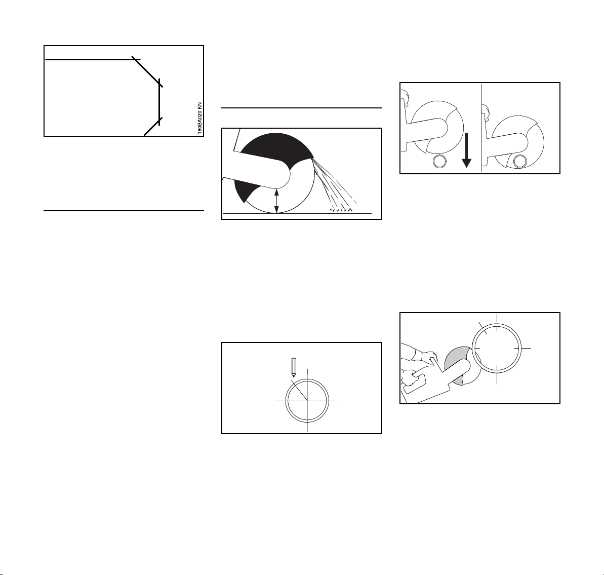
español / EE.UU
N Las curvas se cortan efectuando
varias pasadas rectas procurando
que el disco de corte no se atasque.
Corte de tubos y de piezas redondas y
huecas
N Sujete firmemente los tubos y
piezas redondas y huecas para
evitar que vibren, se resbalen o
rueden.
N Tenga en cuenta el sentido de la
caída y el peso de la pieza cortada.
N Defina y marque la línea de corte.
Evite los refuerzos metálicos
siempre que sea posible,
especialmente en la dirección del
corte divisorio.
N Determine la secuencia de los
cortes divisorios.
N Corte una ranura guía a lo largo de
la línea marcada.
N Profundice los cortes a lo largo de la
ranura guía. Respete la profundidad
de corte recomendada para cada
pasada. Para realizar pequeñas
correcciones en la dirección del
corte, no incline el disco abrasivo;
siempre vuelva a ubicarlo en otra
posición. De ser necesario, deje
partes pequeñas sin cortar que
sujeten la porción que se separará
en su posición. Corte estas partes
pequeñas manualmente después
del último corte.
Corte de tubos de hormigón
A
El procedimiento varía según el
diámetro exterior del tubo y la
profundidad máxima de corte del disco
abrasivo (A).
N Sujete firmemente el tubo para
evitar que vibre, se resbale o ruede.
N Tenga en cuenta el peso, la tensión
y el sentido de la caída de la pieza
que se cortará.
N Defina y marque la dirección del
corte.
N Determine la secuencia de los
cortes.
El diámetro exterior del tubo es más
pequeño que la profundidad máxima del
corte.
N Realice un corte de arriba hacia
abajo.
El diámetro exterior del tubo es más
002BA557 AM
grande que la profundidad máxima del
corte.
Primero planifique y luego corte. Se
requieren varios cortes: es importante
realizarlos en la secuencia correcta.
N Gire el protector hacia el tope
trasero.
N Siempre comience en la parte
002BA528 AM
inferior, y utilice las partes delantera
y superior del disco abrasivo para
cortar.
002BA558 AM
002BA560 AM
TS 410, TS 420
71
Page 74

español / EE.UU
002BA559 AM
180BA026 AM
3
4
Realice el último corte superior una vez
que haya finalizado todos los cortes
inferiores y laterales, y haya conectado
unos con otros.
1
2
N Utilice las partes delantera y
superior del disco abrasivo para
cortar la parte inferior del lado
opuesto. Asegúrese de que el corte
en la parte inferior se realice por
completo.
N A continuación, realice un primer
corte lateral en la mitad superior del
tubo, conectándolo con la ranura de
corte de la mitad inferior.
N Luego, efectúe un segundo corte
lateral en el área marcada. Para
evitar la estricción del tubo durante
este procedimiento, nunca corte el
área del último corte.
002BA561 AM002BA562 AM002BA563 AM
N Siempre efectúe el último corte
separador desde la parte superior
(aproximadamente, 15 % de la
circunferencia del tubo). Si el
material está bien sujeto, no debe
producirse ninguna estricción al
finalizar el corte. Sin embargo, de
ocurrir cualquier estricción residual,
esta se producirá en la parte inferior
del disco, donde podría originarse
un culatazo, pero no un
contragolpe. Esté atento al
culatazo.
Tubo de hormigón - Corte en recovecos
La secuencia de los cortes (1 a 4) es
importante:
N Primero, corte las áreas difíciles de
alcanzar.
180BA024 AM180BA025 AM
N Siempre realice los cortes divisorios
de modo de no ocasionar ninguna
estricción en el disco abrasivo.
N Utilice cuñas y/o deje partes
pequeñas que se rompen después
del corte.
N Si la pieza cortada no se separa del
recoveco después del corte (debido
a las cuñas o partes pequeñas
utilizadas), no siga cortando;
separe la pieza cortada.
72
TS 410, TS 420
Page 75

español / EE.UU
Discos de corte Discos de corte de resina
compuesta
Los discos de corte soportan grandes
cargas, especialmente durante los
cortes manuales.
Solo utilice discos abrasivos que
cumplan con la norma ANSI B 7.1 para
máquinas manuales y posean las
etiquetas correspondientes. Tenga en
cuenta que la velocidad máxima
permitida para el disco de corte debe
superar la velocidad máxima del árbol
que se indica en la etiqueta del protector
del disco.
Los discos de corte desarrollados para
STIHL por fabricantes de discos
abrasivos de buena reputación son de
alta calidad y han sido diseñados
precisamente para la aplicación
específica y para la potencia del motor
de la tronzadora en cuestión.
Transporte y almacenamiento
– No deje los discos de corte a plena
luz del sol ni los exponga a otras
fuentes de calor durante el
transporte y almacenamiento.
– Evite los golpes e impactos.
– Apile los discos de corte
uniformemente sobre una superficie
nivelada, en su embalaje original y
en un lugar seco, con una
temperatura lo más constante
posible.
– No almacene los discos de corte
cerca de fluidos corrosivos.
– Almacene los discos de corte en un
lugar libre de escarcha.
Tipos:
– para cortes en seco
– para cortes en mojado
Se obtienen beneficios económicos y se
evita el desgaste prematuro si se elige y
utiliza el disco de resina compuesta
correcto. El nombre corto (por ej.,
"asfalto", "hormigón")
– en la etiqueta y
– en la envoltura (tabla con usos
recomendados)
ayuda a elegir el modelo correcto.
Dependiendo de la versión, los discos
de corte de resina compuesta de STIHL
pueden usarse para cortar los
materiales siguientes:
– Asfalto
– Hormigón
– Piedra
– Tubos fundidos dúctiles
– Acero: los discos de corte de resina
compuesta de STIHL no pueden
usarse para cortar vías ferroviarias.
No corte ningún otro tipo de material:
¡evite el riesgo de accidentes!
Discos de corte
adiamantados
Para cortes en mojado.
Se obtienen beneficios económicos y se
evita el desgaste prematuro si se elige y
utiliza el disco adiamantado correcto. El
nombre corto (vea la explicación
siguiente)
– en la etiqueta y
– en la envoltura (tabla con usos
recomendados)
ayuda a elegir el modelo correcto.
Dependiendo de la versión, los discos
de corte adiamantados de STIHL
pueden usarse para cortar los
materiales siguientes:
– Asfalto
– Hormigón
– Piedra (roca dura)
– Hormigón abrasivo
– Hormigón fresco
– Ladrillos de arcilla
– Tubos de arcilla
– Hierro dúctil
– Acero estructural de hasta 10 mm
de espesor
TS 410, TS 420
73
Page 76

español / EE.UU
No corte ningún otro tipo de material.
Las tronzadoras no son aptas para
cortar determinados materiales y otras
sustancias.
Nunca utilice discos adiamantados
abrasivos que contengan materiales
abrasivos en sus laterales, puesto que,
en caso de estricción, pueden provocar
un contragolpe excesivo, con el
consiguiente riesgo de provocar
lesiones graves o mortales.
Nombres cortos
El nombre corto es una combinación de
letras y números con hasta cuatro
dígitos:
– Las letras indican el uso principal
del disco de corte.
– Los números identifican la
categoría de rendimiento del disco
adiamantado STIHL.
Letra Uso principal
A Asfalto
B Hormigón
BA Hormigón, asfalto
S Piedra (roca)
SB* Roca, hormigón
*)
puede emplearse con acero estruc
tural de hasta 10 mm de grosor y
con hierro dúctil – no adecuado
para el corte continuo de estos
tipos de materiales
Descentramiento radial y axial
Es indispensable que el cojinete del
árbol esté debidamente montado en la
tronzadora para que el disco
adiamantado tenga una vida útil
prolongada y un funcionamiento
eficiente.
Si se usa un disco de corte en una
tronzadora con un cojinete de árbol
averiado, se puede producir un
descentramiento axial y radial.
El descentramiento axial u oscilación del
eje (B) causa esfuerzos térmicos
elevados y produce cortes más anchos.
-
74
Un descentramiento radial (A) excesivo
causa sobrecargas en segmentos
adiamantados individuales y calor
excesivo. Esto a su vez puede causar
fracturas por esfuerzos en el centro del
disco o el ablandamiento de segmentos
individuales.
TS 410, TS 420
Page 77

Localización de averías
Disco de corte
español / EE.UU
Problema Causa Solución
Bordes ásperos o con roturas, el corte se
Descentramiento radial o axial Consulte con el concesionario
aleja de la línea, aumento del desgaste
de los costados de los segmentos
El disco de corte oscila Utilice un disco de corte nuevo
Bordes ásperos, el corte se aleja de la
línea, rendimiento de corte pobre o nulo,
producción de chispas
El disco de corte está romo; bordes con
acumulación de materiales en los discos
para piedra
Rectifique el disco para trabajar en piedra
cortando brevemente un material abra
sivo; utilice un disco nuevo para cortar
asfalto
Rendimiento deficiente de corte, des
gaste elevado de segmentos
Picaduras o roturas en centro y segmen
tos del disco
Socavamiento Se está cortando un material para el cual el
-
El disco de corte gira en sentido incorrecto Instale el disco de corte con el sentido de
rotación correcto
-
Sobrecarga Sustituya el disco de corte inmediata
mente por uno nuevo
Utilice un disco de corte nuevo; tome nota
disco no ha sido diseñado
de las capas de corte distintas de mate
riales diferentes
1)
STIHL recomienda acudir a un concesionario STIHL para servicio.
1)
-
-
-
TS 410, TS 420
75
Page 78

español / EE.UU
Socavamiento
El socavamiento es el desgaste del
núcleo de acero en los segmentos
adiamantados o justo debajo de ellos.
Cuando se cortan superficies
pavimentadas, no corte más
profundamente en la capa abrasiva
(grava, piedra picada) bajo la superficie,
la cual se indica porque produce un
polvo de color claro. Esto causa un
socavamiento excesivo, lo cual produce
la rotura y/o el lanzamiento de
segmentos del disco.
ADVERTENCIA
Reemplace un disco adiamantado de
inmediato si su centro tiene
socavamiento severo.
Bordes con acumulaciones,
rectificación
Los bordes con acumulaciones se
identifican por medio de depósitos gris
claro encima de los segmentos
adiamantados que obturan y reducen el
filo de los segmentos.
Los bordes pueden formar
acumulaciones:
– cuando se cortan materiales
extremadamente duros, tales como
el granito,
– como resultado del manejo
incorrecto, como la aplicación de
fuerza excesiva.
Los bordes con acumulaciones
aumentan las vibraciones, reducen el
rendimiento de corte y producen
chispas.
Los discos de corte adiamantados
requieren ser "rectificados" cuando se
producen señas de acumulaciones en
los bordes. Con este fin, corte
brevemente en un material de calidad
más abrasiva, tal como arenisca,
hormigón aireado o asfalto.
El corte mojado ayuda a evitar la
formación de acumulaciones en los
bordes.
Si se continúa usando un disco con
segmentos romos, éstos podrían
ablandarse como resultado del
calentamiento excesivo. El centro del
disco también se sobrecalienta y pierde
su resistencia mecánica. Esto puede
causar esfuerzos grandes, los cuales se
indican claramente por medio de las
roturas de esfuerzo y/o movimientos de
oscilación del disco.
ADVERTENCIA
Estos discos de corte pueden quebrarse
o lanzar algunos de sus segmentos
durante el uso, o causar fuerzas de
reacción significativas, causando
lesiones graves o mortales.
Reemplácelos de inmediato.
76
TS 410, TS 420
Page 79

español / EE.UU
1307BA001 KN
2
1
370BA085 KN
3
Sistema de control
electrónico de agua
Las tronzadoras STIHL podrían tener un
equipo electrónico de control de agua.
El sistema de control electrónico de
agua permite entregar la cantidad de
agua óptima al disco de corte. No se
entrega agua al disco de corte cuando la
máquina está en marcha en vacío o
apagada.
Antes de empezar a trabajar
N Con el motor apagado,
familiarícese con el tablero de
control y las secuencias de
movimientos necesarios.
N Todos los botones del tablero de
control están al alcance del pulgar
de la mano derecha cuando la
misma queda en el mango trasero.
N La mano izquierda siempre queda
en la barra de empuñadura.
Tablero de control
Cuando el motor está en marcha, se
puede activar/desactivar el sistema de
control electrónico de agua y regular el
caudal de agua.
1 Botón (+):
activa el sistema de control
electrónico de agua o aumenta el
caudal de agua suministrado al
disco de corte.
2 Botón (–):
activa el sistema de control
electrónico de agua o reduce el
caudal de agua suministrado al
disco de corte.
3 Desactiva el sistema de control
electrónico de agua; no se
suministra agua al disco de corte.
Uso del sistema de control electrónico
de agua
N Arranque el motor: consulte el
capítulo "Arranque/parada del
motor."
N Pulse momentáneamente el
botón (+) o (–) con el pulgar de la
mano derecha. La mano derecha
siempre debe mantenerse en el
mango trasero al hacerlo; la mano
izquierda siempre debe quedar en
la barra de empuñadura. No se
suministra agua al disco de corte
durante el funcionamiento a marcha
en vacío.
Durante el uso, la cantidad de agua
establecida se suministra al disco de
corte.
N Ajuste el caudal de agua según sea
necesario – para hacerlo, pulse
momentáneamente el botón (+) o (–
) con el pulgar de la mano derecha
hasta que se obtenga la cantidad de
agua correcta en una de las
posiciones de regulación. La mano
derecha siempre debe mantenerse
en el mango trasero al hacerlo; la
mano izquierda siempre debe
quedar en la barra de empuñadura.
La presión de agua afectará el caudal
real de agua en cualquiera de las
posiciones de regulación. Puede ser
necesario usar una posición de
regulación más alta con una presión de
agua baja, por ejemplo, cuando se usa
un tanque de agua a presión o de flujo
por gravedad. Para suprimir el polvo y
obtener el rendimiento de corte
deseado, siempre asegúrese que el
caudal de agua esté dentro del intervalo
correcto, tal como se describe en el
capítulo "Ejemplos de usos."
Si la tronzadora está en marcha en
vacío después del uso, el sistema de
control electrónico de agua queda
activado pero no se suministra agua al
disco de corte. Al reanudar el trabajo, se
aplicará automáticamente la última
posición de regulación empleada.
Si se para el motor y se lo vuelve a
arrancar, el control electrónico de agua
se desconecta.
TS 410, TS 420
77
Page 80
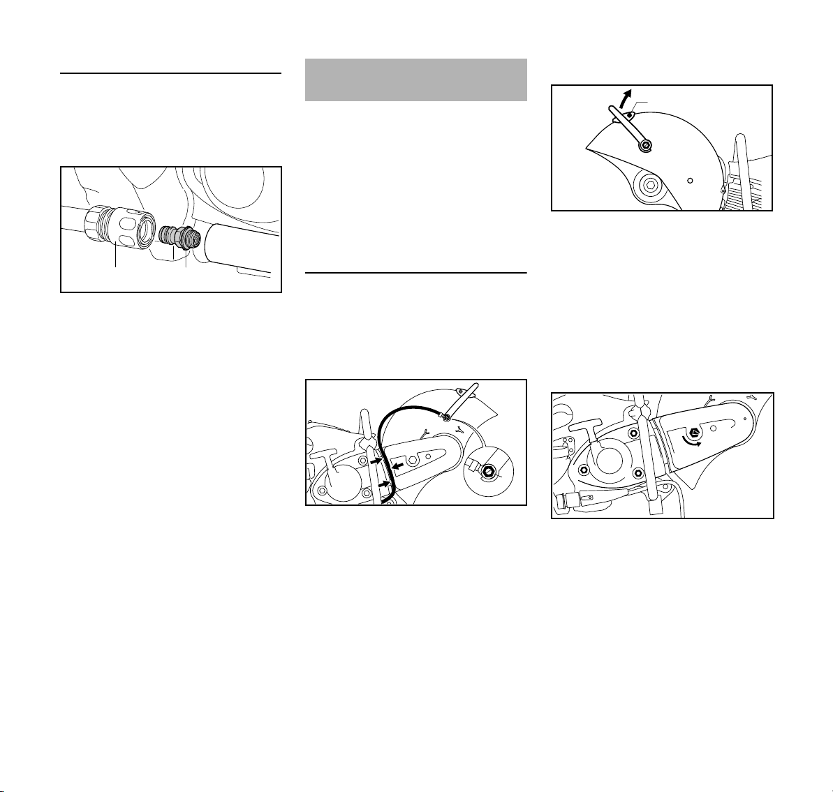
español / EE.UU
2
370BA086 KN
1
1
1
2
370BA068 KN
3
2
370BA069 KN
1
3
1
1
1
2
370BA070 KN
0
Mantenimiento y cuidado
Si no se suministra suficiente agua al
disco de corte durante el uso, a pesar de
que el sistema de control electrónico de
agua ha sido activado:
N quite el manguito acoplador (1);
N destornille la "conexión de agua con
tamiz" (2) y lávela en un chorro de
agua corriente - el tamiz queda
fijado a la conexión de agua.
Armado del brazo fundido y
protector
El fabricante instala el "brazo fundido
con protector" en el lado interior.
El "brazo fundido con protector" también
puede instalarse en el lado exterior,
dependiendo de los requerimientos.
Debido al equilibrio mejorado, se
recomienda la instalación en el lado
interior para el corte a mano libre.
Montaje al exterior
N Desmonte el disco de corte (vea
"Colocación / sustitución de un
disco de corte")
Quite el accesorio de agua
Retiro de la palanca de ajuste
N Destornille con la llave combinada
el perno banjo (1) y sáquelo con el
sello – al hacerlo, quite la tuerca
cuadrada de la guía del interior del
protector
N Quite el tornillo (2)
N Gire la palanca de ajuste (3) hacia
arriba y quítela
Aflojamiento de la correa trapezoidal
N Destornille con la llave combinada
el perno banjo (1) – al hacerlo, quite
la tuerca cuadrada de la guía del
interior del protector
N Quite la manguera de agua (2) con
su conector de la palanca de
ajuste (3)
N Extraiga la manguera de agua (2)
fuera de la guía (flechas) en el
protector de la correa trapezoidal
N Destornille las tuercas (1) - no los
quite
N Gire la tuerca tensora (2) en sentido
contrahorario con la llave
combinada – aprox. 1/4 de vuelta,
hasta que tope = 0
78
TS 410, TS 420
Page 81
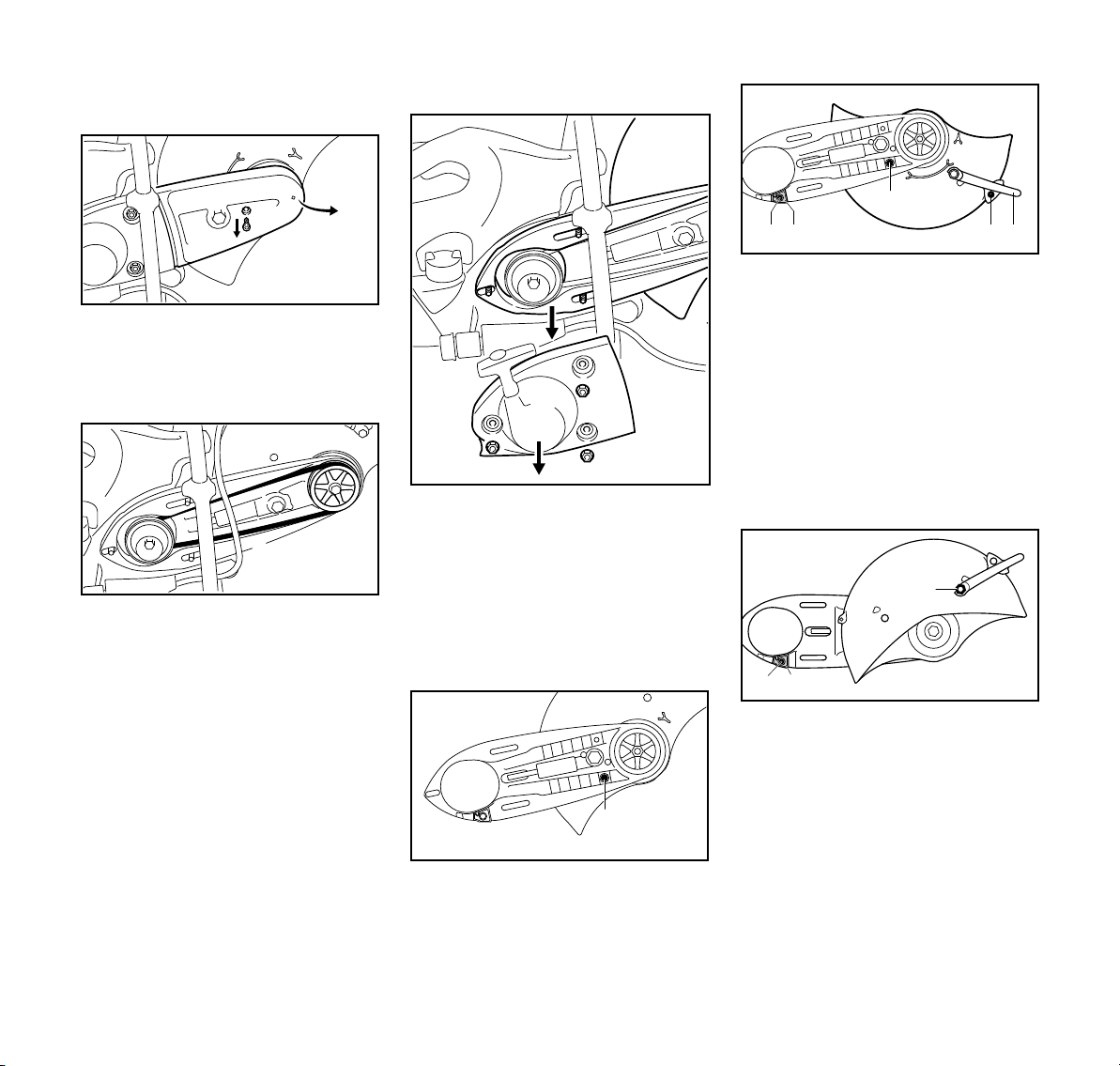
español / EE.UU
2
1
370BA071 KN
3
370BA079 KN
4
370BA072 KN
1
2
3
1
1
1
370BA073 KN
1
370BA074 KN
4 5
3
2
A
4
5
370BA075 KN
6
Retiro del protector de la correa
trapezoidal
N Quite el tornillo (1)
N Eleve un poco el protector de la
correa trapezoidal (2) y extráigalo
hacia adelante
N Quite la correa trapezoidal (3) de la
polea delantera (4)
Quite el "brazo fundido con protector"
N Destornille las tuercas (1)
N Quite la "cubierta del arrancador
con arrancador de cuerda" (2)
N Quite el "brazo fundido con
protector" (3) de los espárragos
Preparación del "brazo fundido con
protector" para montaje al exterior
N Gire el protector a la posición
ilustrada (vea la ilustración)
N Atornille y apriete el pasador de
tope (1)
N Mueva la palanca de ajuste (2) a la
posición A
N Atornille el perno (3) y apriételo
N Destornille el perno (4) del tope
limitador (5)
N Quite el tope limitador (5)
TS 410, TS 420
N Gire el "brazo fundido con protector"
para que el protector quede en el
lado exterior
N Inserte el tope limitador (5) – alinee
el agujero en el tope limitador con el
N Destornille el pasador de tope (1)
agujero en el brazo fundido
N Atornille el perno (4) y apriételo
79
Page 82

español / EE.UU
1
1
2
2
370BA008 KN
1
2
4
3
6
6
2
2
2
370BA051 KN
6
5
8
370BA077 KN
7
1
1
370BA078 KN
2
3
N Introduzca la tuerca cuadrada en la
guía en el protector y reténgala en
su lugar
N Atornille el perno banjo más
corto (6) y la arandela en la palanca
de ajuste y apriételos con la llave
combinada
Monte el "brazo fundido con protector" –
con el protector en el lado exterior
N Instale la "cubierta de arrancador
con arrancador de cuerda" (5)
sobre los espárragos (2)
N Apriete las tuercas (6) con la mano
N Empuje el protector de la correa
trapezoidal (7) en su lugar
N Atornille el perno (8) y apriételo
Conexión de agua
N Inserte el perno banjo más largo (1)
a través del conector (2) del
accesorio para agua – observe la
posición del conector
N Introduzca la tuerca cuadrada en la
guía en el protector y reténgala en
su lugar
N Instale el soporte con el perno banjo
más largo en la palanca de
ajuste (3) – atornille el perno banjo y
apriételo con la llave combinada
N Introduzca la manguera de agua del
grifo de corte en la guía en el
protector de la correa trapezoidal
(flecha) hacia el protector - evite
radios de curvatura aguda
N Empuje los agujeros cuadrados (1)
en el "brazo fundido con protector"
en los espárragos(2), guiando la
correa trapezoidal nervada sobre la
polea delantera
INDICACIÓN
Debe ser posible desplazar suavemente
la correa.
N El tensor de la correa (3) debe
quedar cerca de la orejeta (4)
80
TS 410, TS 420
Page 83
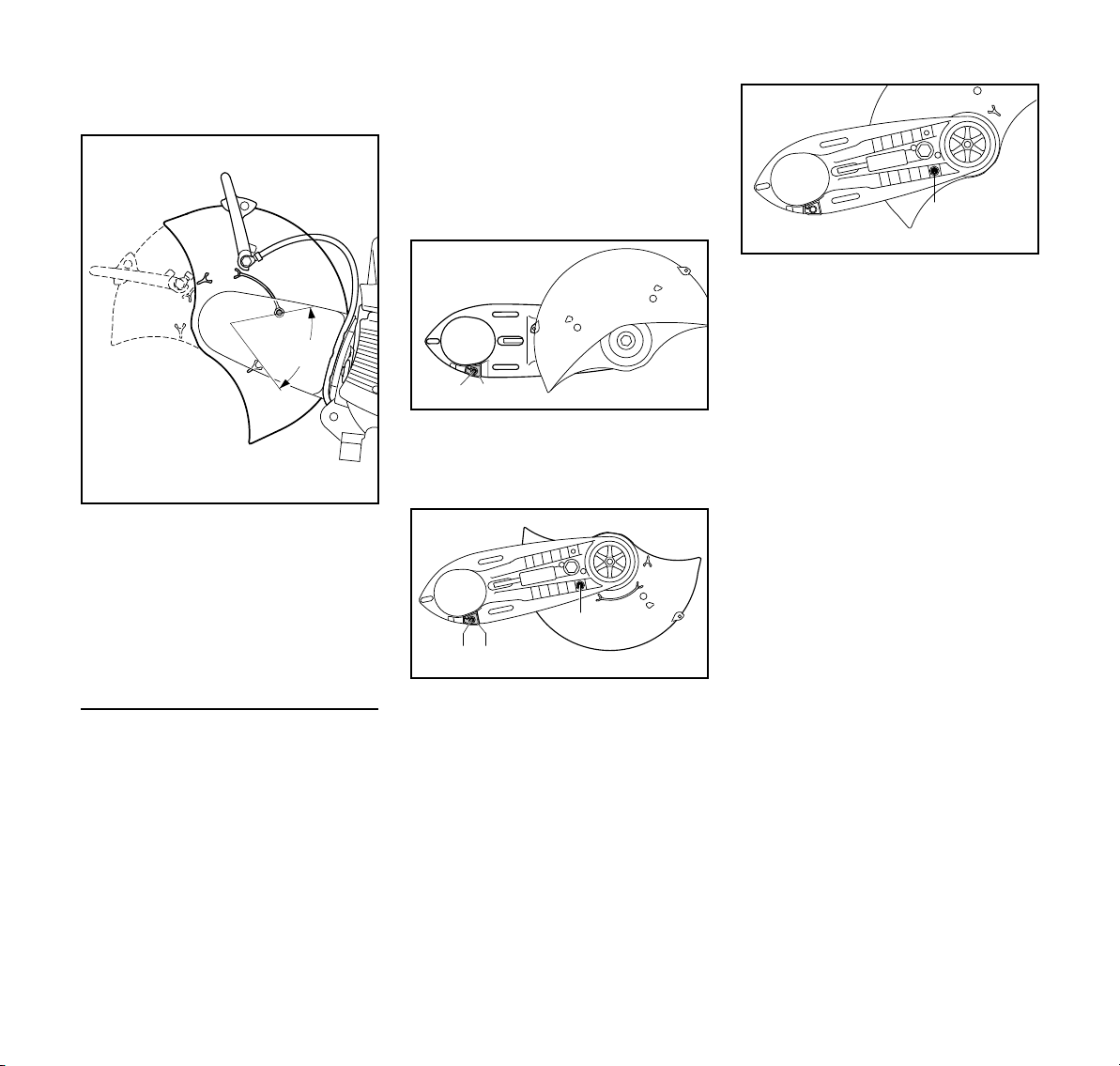
español / EE.UU
370BA076 KN
A
1
2
370BA080 KN
3
370BA081 KN
1
2
3
370BA082 KN
Revisión del intervalo de ajuste del
protector
N Gire el protector en lo posible hacia
adelante y atrás – el pasador de
tope (A) debe limitar el intervalo de
ajuste
Proceda de la manera indicada en el
capítulo "Tensado de la correa
trapezoidal".
N Quite el protector de la correa
trapezoidal
N Quite el "brazo fundido con
protector"
Preparación del "brazo fundido con
protector" para montaje al interior
N Destornille el tornillo (1) del tope
limitador (2)
N Quite el tope limitador (2)
N Gire el protector a la posición
ilustrada (vea la ilustración)
N Atornille y apriete el pasador de
tope (3)
N Instale la palanca de ajuste
N Monte el "brazo fundido con
protector" – con el protector en el
lado interior
N Coloque el protector de la correa
trapezoidal
N Conexión de agua
Montaje al interior
N Desmonte el disco de corte (vea
"Colocación / sustitución de un
disco de corte")
N Quite el accesorio de agua
N Quite la palanca de ajuste
N Suelte la correa trapezoidal
TS 410, TS 420
N Gire el "brazo fundido con protector"
para que el protector quede en el
lado interior
N Inserte el tope limitador (2) – alinee
el agujero en el tope limitador con el
agujero en el brazo fundido
N Atornille el perno (1) y apriételo
N Destornille el pasador de tope (3)
81
Page 84

español / EE.UU
A
370BA083 KN
1
1
1
2
370BA037 KN
0
1
1
1
370BA012 KN
1
1
1
370BA013 KN
Revisión del intervalo de ajuste del
protector
N Gire el protector en lo posible hacia
adelante y atrás – el pasador de
tope (A) debe limitar el intervalo de
ajuste
Proceda de la manera indicada en el
capítulo "Tensado de la correa
trapezoidal".
Tensado de la correa
trapezoidal nervada
Esta máquina tiene un dispositivo
automático con resorte para tensar la
correa trapezoidal.
Antes de tensar la correa trapezoidal
nervada, es necesario soltar las
tuercas (1) y la flecha en la tuerca
tensora (2) debe apuntar a 0.
N de lo contrario, afloje las tuercas (1)
y la tuerca tensora (2) en sentido
contrahorario con la llave
combinada – aprox. 1/4 de vuelta,
en lo posible = 0
ADVERTENCIA
La tuerca tensora está tensada por
resorte – agarre firmemente la llave
combinada.
N Gire la tuerca tensora aprox. 1/8 de
vuelta en sentido horario para que
el resorte encaje la misma
N Siga girándola aprox. 1/8 de vuelta
– hasta el tope
INDICACIÓN
No siga girando la llave combinada con
mucha fuerza.
En esta posición la fuerza del resorte
tensa automáticamente la correa
trapezoidal nervada.
N Quite la llave combinada de la
tuerca tensora
N Apriete las tuercas (1)
Tensado de nuevo de la correa
trapezoidal nervada
N para tensar la correa trapezoidal
nervada, coloque la llave
combinada sobre la tuerca tensora,
tal como se ilustra
82
No es necesario ajustar la tuerca
tensora para volver a tensar la correa
trapezoidal.
TS 410, TS 420
Page 85
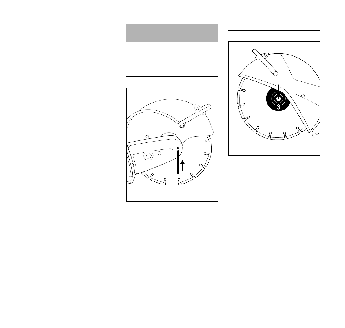
español / EE.UU
370BA014 KN
1
2
370BA053 KN
N Afloje las tuercas (1)
La fuerza del resorte tensa
automáticamente la correa trapezoidal.
N Vuelva a apretar las tuercas (1)
Colocación / sustitución de
un disco abrasivo
Es necesario apagar el motor para la
instalación o sustitución – ponga el
control deslizante en STOP o 0.
Bloqueo del eje
Retiro de un disco de corte
N Use la llave combinada para aflojar
y quitar el tornillo de cabeza
hexagonal (2).
N Retire la arandela de empuje
delantera (3) (brida) del eje junto
con el disco de corte
TS 410, TS 420
N Deslice el pasador de bloqueo (1) a
través de la cavidad en el protector
de la correa trapezoidal
N Haga girar el eje con la llave
combinada hasta que el pasador de
bloqueo (1) se encaje en la cavidad
detrás del protector
83
Page 86
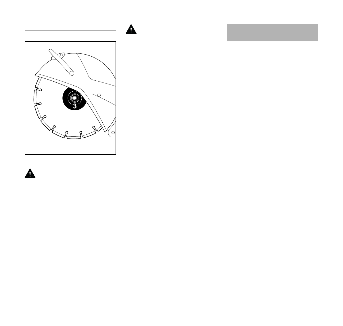
español / EE.UU
370BA054 KN
4
Instalación de un disco de corte nuevo
N Instale el nuevo disco de corte (4)
ADVERTENCIA
Observe las flechas que indican el
sentido de giro en los discos de corte
adiamantados.
N Coloque la arandela de empuje
delantera (3). Las trabas de la
arandela de empuje delantera (3)
(brida) deben engancharse en las
ranuras del eje.
N Atornille el perno hexagonal y
apriételo con la llave combinada – si
está usando una llave torsiométrica,
vea el par de apriete en las
"Especificaciones"
N Extraiga el pasador de bloqueo del
protector de la correa trapezoidal.
ADVERTENCIA
No use dos discos de corte al mismo
tiempo. El desgaste desigual resulta en
un ¡riesgo de rotura y la posibilidad de
lesiones!
Combustible
Este motor está certificado para
funcionar con una mezcla de 50 a 1 de
gasolina sin plomo y aceite STIHL para
motores de dos tiempos.
Su motor requiere una mezcla de
gasolina de alta calidad y aceite para
motores de dos tiempos enfriados por
aire.
Utilice gasolina sin plomo de grado
intermedio con un octanaje mínimo de
89 ((R+M)/2) y un contenido de etanol
no mayor que el 10%.
El combustible de octanaje bajo puede
aumentar la temperatura de
funcionamiento del motor. Esto, a su
vez, aumenta el riesgo de que se
agarrote el pistón y se dañe el motor.
La composición química del
combustible también es importante.
Algunos aditivos de combustible no
solamente tienen efectos perjudiciales
en los elastómeros (diafragmas de
carburador, sellos de aceite, tuberías de
combustible, etc.), sino también en las
piezas fundidas de magnesio y en los
convertidores catalíticos. Esto podría
causar problemas de funcionamiento e
incluso daño del motor. Por esta razón,
STIHL recomienda el uso exclusivo de
gasolina sin plomo reconocida de buena
calidad.
La gasolina con un contenido de etanol
mayor que el 10% puede causar
problemas de funcionamiento y averías
graves en motores, por lo cual no debe
utilizarse.
84
TS 410, TS 420
Page 87
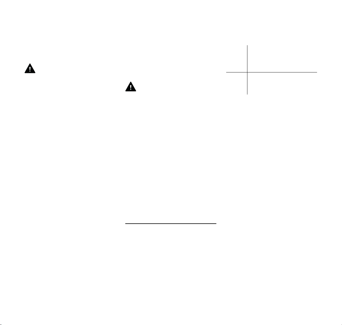
español / EE.UU
El contenido de etanol en la gasolina
afecta el régimen de marcha del motor –
podría resultar necesario reajustar el
carburador si se utilizan combustibles
con diversos niveles de contenido de
etanol.
ADVERTENCIA
Para reducir el riesgo de lesiones
personales debido a la pérdida de
control y/o al contacto con la
herramienta de corte en movimiento, no
use una máquina cuyo régimen de
marcha en vacío está mal regulado.
Cuando el marcha en vacío está
correctamente regulado, la herramienta
de corte no debe moverse.
Si su herramienta motorizada indica que
el régimen de marcha en vacío está mal
regulado, pida a su representante de
STIHL que revise la herramienta
motorizada y haga los ajustes o
reparaciones correspondientes.
Las velocidades de ralentí y máxima del
motor varían si se cambia el
combustible por otro con un contenido
mayor o menor de etanol.
Este problema se evita si siempre se
utiliza combustible con un mismo
contenido de etanol..
Use solamente el aceite STIHL para
motores de dos tiempos o un aceite de
marca equivalente para motores de dos
tiempos diseñado para usar
exclusivamente con los motores de dos
tiempos enfriados por aire.
Se recomienda usar aceite STIHL HP
Ultra para motores de 2 tiempos, puesto
que éste ha sido formulado
especialmente para uso en motores
STIHL.
No use aceites para mezclar con
designaciones BIA o TCW (para
motores de dos tiempos enfriados por
agua) ni otros aceites para mezclar
diseñados para usar en motores
enfriados por agua o por aire (por
ejemplo, en motores marinos fuera de
borda, motonieves, sierras de cadenas,
bicimotos, etc.).
ADVERTENCIA
Manipule la gasolina con sumo cuidado.
Evite el contacto directo con la piel y
evite inhalar los vapores de
combustible. Cuando se reabastece de
combustible, quite primero el envase del
vehículo y colóquelo en el suelo antes
de llenarlo. Para reducir el riesgo de la
formación de chispas causadas por la
descarga de electricidad estática y un
posible incendio y/o explosión, no llene
los envases de combustible cuando
están colocados dentro de un vehículo o
remolque.
Mantenga el envase bien cerrado para
limitar la cantidad de humedad que
penetre en la mezcla.
Limpie el tanque de combustible de la
máquina según sea necesario.
Duración de la mezcla de combustible
Mezcle una cantidad suficiente de
combustible para trabajar unos pocos
días, no lo guarde por más de 30 días.
Guárdelo únicamente en envases
aprobados para combustible. Para el
proceso de mezclado, vierta el aceite en
el envase primero y luego agregue la
gasolina. Cierre el envase y agítelo
vigorosamente a mano para asegurar
que se mezclen bien el aceite y la
gasolina.
-
Gaso
lina
gal
EE.UU.
12,6
2 1/2 6,4
5 12,8
Deseche los envases vacíos usados
para mezclar el aceite únicamente en
vertederos autorizados para ello.
Aceite (STIHL 50:1 ó aceite
de alta calidad equivalente)
oz fl
EE.UU.
TS 410, TS 420
85
Page 88
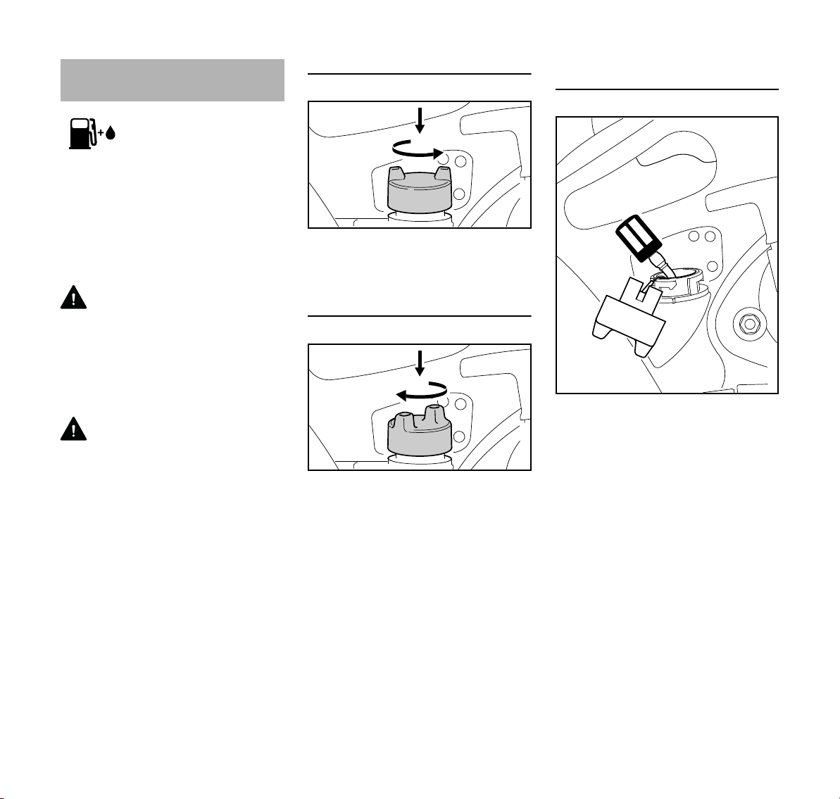
español / EE.UU
1.
2.
370BA017 KN
1.
2.
370BA018 KN
370BA019 KN
Llenado de combustible
Antes de llenar la máquina con
combustible, limpie la tapa de llenado y
la zona alrededor de la misma para
evitar la entrada de tierra al tanque.
Agite bien la mezcla en el recipiente
antes de llenar la máquina con
combustible.
ADVERTENCIA
Para evitar el riesgo de incendios y
lesiones ocasionadas por los escapes
de vapor de gasolina, abra la tapa de
llenado de combustible cuidadosamente
para que la presión excesiva en el
tanque pueda escapar lentamente.
ADVERTENCIA
Nunca utilice herramientas para abrir o
cerrar la tapa tipo bayoneta. Esto puede
dañar la tapa y permitir el escape de
combustible.
No derrame combustible y no llene en
exceso el tanque.
Abra la tapa de llenado de combustible
Presione a fondo la tapa con la mano,
gírela en sentido contrahorario
(aprox. 1/8 de vuelta) y quítela.
Cierre la tapa de llenado de combustible
N Coloque la tapa y gírela hasta que
se encaje en el punto de montaje
tipo bayoneta.
N Presione a fondo la tapa con la
mano y gírela en sentido horario
(aprox. 1/8 de vuelta) hasta que se
encaje completamente. Revisar el
apriete de la tapa.
Cambie el recogedor de combustible
una vez al año
N Vacíe el tanque de combustible.
N Extraiga el recogedor de
combustible del tanque con un
gancho y desconéctelo de la
manguera.
N Conecte un nuevo recogedor de
combustible a la manguera.
N Vuelva a colocar el recogedor de
combustible en el tanque.
86
TS 410, TS 420
Page 89

español / EE.UU
START
1
3
3
370BA020 KN
2
370BA055 KN
Choke
4
5
370BA101 KN
Arranque / parada del motor
N Pulse simultáneamente el bloqueo
del gatillo de aceleración (1) y el
gatillo de aceleración (2)
N Mantenga los dos gatillos oprimidos
N Mueva el control deslizante (3)
hacia la posición START y
manténgalo en esa posición
también
N Después suelte sucesivamente el
gatillo, la palanca de control y el
bloqueo del gatillo – la posición de
arranque
N Ajuste la palanca del
estrangulador (4) según la
temperatura del motor
c Si el motor está frío
e si el motor está tibio (incluso
cuando el motor está en marcha
pero todavía frío o si el motor tibio
ha sido apagado por menos de
5min)
f si el motor está caliente (el motor
caliente ha sido apagado durante
más de 5 min)
Versiones con válvula de
descompresión
N Pulse el botón (5) de la válvula de
descompresión antes de cada
intento de arranque
TS 410, TS 420
87
Page 90

español / EE.UU
6
370BA102 KN
370BA092 KN
4
370BA057 KN
Choke
Para todas las versiones
N Comprima el bulbo (6) de la bomba
de combustible manual 7-10 veces
– aunque el bulbo esté lleno de
combustible
Arranque
pueda tocar ningún objeto ni el
suelo Asegúrese que no haya nadie
dentro del alcance de la sierra
N Asegúrese de tener los pies bien
apoyados
N Presione la tronzadora firmemente
contra el suelo agarrando el mango
con la mano izquierda con el dedo
pulgar alrededor del mango
N Presione la tronzadora contra el
suelo colocando su rodilla derecha
en la envuelta
N Con la mano derecha tire
lentamente del mango de arranque
hasta que sienta el engrane – en
seguida dele un tirón fuerte y rápido
– no tire de la cuerda de arranque
totalmente hasta fuera
INDICACIÓN
No deje que el mango de arranque salte
bruscamente hacia atrás. ¡Puede
romperse! Guíelo lentamente en la caja
para que se enrolle correctamente.
Después de hacer girar el motor por
primera vez
N Ponga la palanca del estrangulador
(4) en f
N Pulse el botón de la válvula de
descompresión (depende del
modelo).
N siga intentando el arranque
Cuando el motor se encuentre en
marcha
N Oprima a fondo el gatillo de
aceleración y deje el motor
funcionar a máxima aceleración por
aprox. 30 s
N Cuando el motor está caliente,
ponga la palanca del estrangulador
en e
N Coloque la tronzadora
cuidadosamente sobre el suelo y
asegúrese que el disco abrasivo no
88
TS 410, TS 420
Page 91
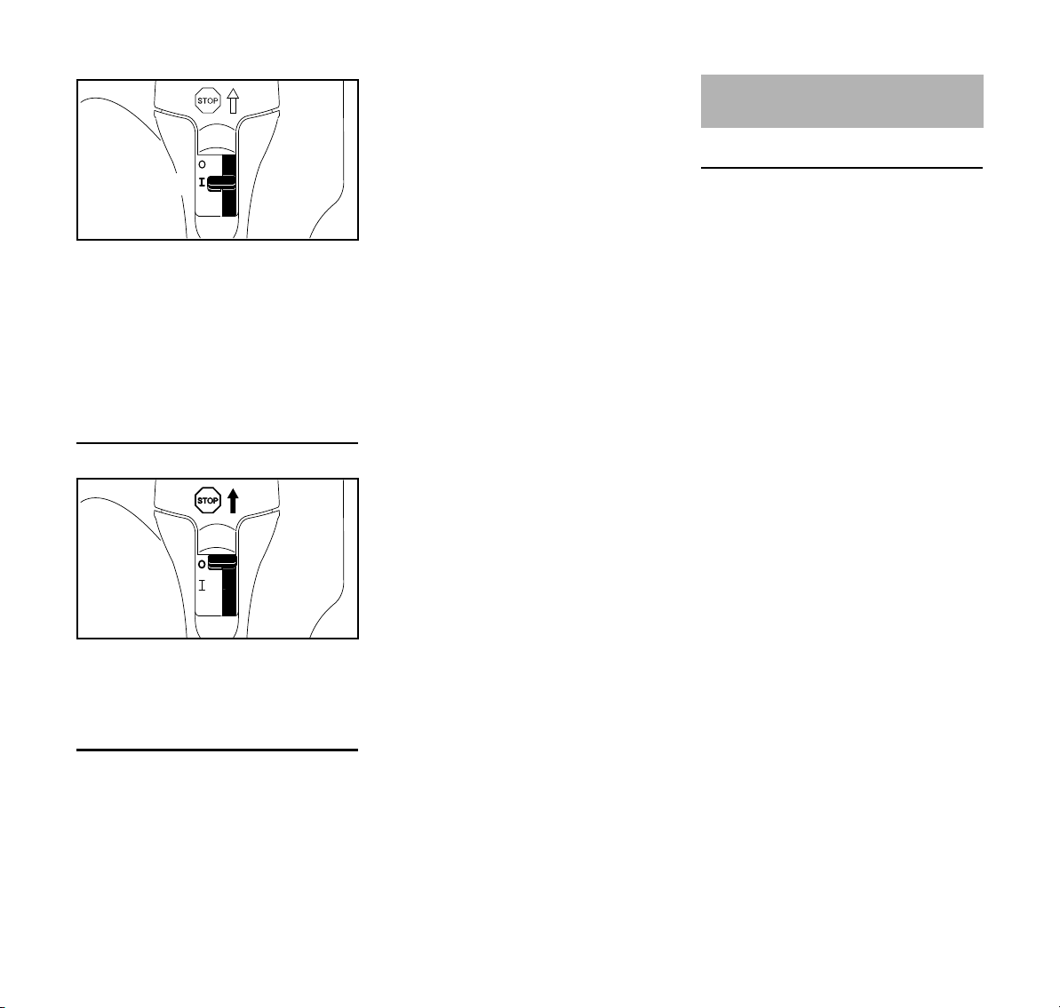
español / EE.UU
370BA058 KN
START
3
370BA059 KN
START
3
N El control deslizante (3) se mueve a
la posición normal F cuando se
oprima el gatillo de aceleración.
Si el carburador está debidamente
ajustado, el disco abrasivo no gira
cuando el motor funciona a ralentí.
La tronzadora está lista para usarse.
Apagado del motor
N Coloque el control deslizante en
START = la posición de arranque
N Ponga la palanca del estrangulador
en e = la posición de arranque
tibio, aun si el motor está frío
N Tire de la cuerda de arranque 10-20
veces para despejar la cámara de
combustión
N Vuelva a arrancar el motor
Si el tanque ha sido completamente
vaciado
N Carga de combustible
N Oprima el bulbo de la bomba de
combustible manual 7-10 veces,
aunque el bulbo esté lleno de
combustible.
N Ajuste la palanca del estrangulador
según la temperatura del motor
N Vuelva a arrancar el motor
Sistema de filtro de aire
Información básica
La vida útil promedio del filtro es más de
1 año. No desarme la cubierta del filtro
ni instale un filtro de aire nuevo a menos
que se produzca una pérdida notable de
potencia del motor.
En el sistema de filtro de aire de larga
vida útil con el sistema ciclónico de
separación inicial, el aire sucio se aspira
y se hace girar a propósito. De esta
manera se expulsan y extraen las
partículas grandes y pesadas llevadas
por la corriente de aire. Solamente el
aire prefiltrado entra al sistema de filtro
de aire y, como resultado, el filtro tiene
una vida útil extremadamente larga.
N Ponga el control deslizante (3) en
STOP o 0
Sugerencias adicionales para el
arranque
Si el motor no arranca
La palanca del estrangulador no se
colocó en la posición f en el momento
necesario después del primer intento de
arranque.
TS 410, TS 420
89
Page 92

español / EE.UU
1
2
3
4
370BA028 KN
1
1
Sustitución del filtro de aire
Solamente si hay una pérdida notable
de la potencia del motor
N Palanca del estrangulador en c
N Afloje los tornillos (1)
N Quite la cubierta del filtro (2) y
límpiela
N Retire el filtro principal (3)
N Quite el filtro auxiliar (4) –
asegúrese que la suciedad no entre
en la zona de admisión
N Limpie la zona del filtro de aire
N Introduzca un filtro auxiliar nuevo y
N Vuelva a colocar la cubierta del filtro
N Apriete los tornillos
un filtro principal nuevo
Siempre utilice los filtros de aire STIHL
originales. La alta calidad de estos
componentes aseguran el
funcionamiento sin problemas, una
larga vida útil del motor y una vida útil
extremadamente larga del filtro.
Gestión del motor
Las emisiones de gases de escape son
controladas por el diseño de parámetros
y componentes fundamentales del
motor (por ej. carburación, encendido,
regulación y regulación de las válvulas o
la lumbrera) sin la adición de ningún
equipo importante.
90
TS 410, TS 420
Page 93

español / EE.UU
370BA029 KN
370BA090 KN
Ajuste del carburador
Información básica
El sistema de encendido de esta sierra
tiene un limitador electrónico de
velocidad máxima. No es posible
aumentar la velocidad máxima más allá
de un límite especificado.
El carburador se ajusta en la fábrica al
ajuste estándar.
El carburador ha sido ajustado para el
rendimiento y la eficiencia de uso de
combustible óptimos en todas las
condiciones de funcionamiento.
Preparación de la máquina
N Apague el motor
N Revise el filtro de aire y límpielo o
sustitúyalo de ser necesario.
N Revise el chispero del silenciador
(depende del país) y límpielo o
sustitúyalo de ser necesario
Ajuste estándar
N Gire el tornillo de ajuste de
velocidad alta (H) en sentido
contrahorario hasta su tope (no más
de 3/4 de vuelta)
N Cuidadosamente gire el tornillo de
ajuste de velocidad baja (L)
completamente en sentido horario,
y luego gírelo 3/4 de vuelta en
sentido contrahorario
Ajuste de la velocidad de marcha en
vacío
N Establezca el ajuste normal
N Arranque el motor y caliéntelo
El motor se para durante el
funcionamiento a marcha en vacío
N Atornille el tornillo de ajuste de
marcha en vacío (LA) en sentido
horario hasta que el disco abrasivo
empiece a girarse y luego
destorníllelo en 1 vuelta
El disco abrasivo gira con el motor a
marcha en vacío
N Gire el tornillo de marcha en
vacío (LA) en sentido contrahorario
hasta que el disco abrasivo se
detenga y luego otra
vuelta completa en el mismo
sentido.
ADVERTENCIA
Si el disco abrasivo sigue girando con el
motor en marcha en vacío después de
llevarse a cabo el ajuste, pida que un
concesionario de servicio revise la
máquina.
TS 410, TS 420
Velocidad de marcha en vacío errática;
aceleración inadecuada (aunque se ha
corregido el ajuste de LA)
Ajuste de marcha en vacío con mezcla
muy pobre.
91
Page 94

español / EE.UU
2
370BA031 KN
1
N Gire el tornillo de ajuste de
velocidad baja (L) aprox. 1/4 de
vuelta en sentido contrahorario
hasta que el motor funcione y
acelere de modo uniforme – no más
allá del tope.
No es posible aumentar suficientemente
la velocidad de marcha en vacío usando
el tornillo de ajuste de marcha en
vacío (LA), el motor se para al cambiar
de carga parcial a marcha en vacío
Ajuste de marcha en vacío con mezcla
muy rica.
N Gire el tornillo de ajuste de
velocidad baja (L) aprox. 1/4 de
vuelta en sentido horario.
Cuando se ajusta el tornillo de velocidad
baja (L), normalmente es necesario
ajustar también el tornillo de ajuste de
marcha en vacío (LA).
Corrección del ajuste del carburador
para uso a alturas grandes
El ajuste puede requerir una corrección
mínima si el rendimiento del motor es
insatisfactorio a alturas elevadas:
N Establezca el ajuste normal
N Permita que el motor se caliente
N Gire el tornillo de ajuste de
velocidad alta (H) ligeramente en
sentido horario (mezcla más pobre)
– no más allá del tope
Si el ajuste es demasiado pobre, existe
riesgo de dañar el motor debido a una
lubricación insuficiente y
sobrecalentamiento.
Chispero en el silenciador
En algunos países, los silenciadores
tienen un chispero.
N Si el motor pierde potencia, revise el
chispero en el silenciador.
ADVERTENCIA
Espere a que el motor se enfríe por
completo antes de efectuar las
operaciones siguientes.
N Quite el tornillo (1)
N Extraiga el chispero (2) hacia
arriba, fuera del silenciador
N Limpie el chispero contaminado
N Si el chispero está dañado o con
depósitos gruesos de carbón,
instale uno nuevo
N Vuelva a instalar el chispero
invirtiendo el orden de los pasos de
retiro
INDICACIÓN
Si se ha descendido de una altura
elevada, restaure el carburador al ajuste
estándar.
92
TS 410, TS 420
Page 95

Bujía
1307BA030 KN
1
2
4
1307BA031 KN
3
000BA039 KN
A
1
2
000BA071 KN
Si el motor pierde potencia, es difícil
arrancarlo o funciona de modo irregular
a ralentí, revise la bujía primero.
Instale una bujía nueva después de
aprox. 100 horas de funcionamiento, o
más temprano si los electrodos están
muy gastados.
Si la mezcla del combustible es
incorrecta (demasiado aceite en la
gasolina), el filtro de aire está sucio, y
las condiciones de trabajo no son
favorables (especialmente a
aceleraciones intermedias) se afecta la
condición de la bujía. Estos factores
permiten la formación de depósitos en la
punta aislante, los cuales pueden
perjudicar el rendimiento.
Retiro de la bujía
N Pare el motor – mueva el interruptor
de parada a PARADA o 0
N Desenrosque el tornillo (1) y retire la
tapa (2) – el tornillo (1) está fijado a
la tapa (2) para evitar que se
extravíe.
TS 410, TS 420
N Quite el casquillo de la bujía (3).
N Destornille la bujía (4).
Revisión de la bujía
N Limpie la bujía si está sucia.
N Revise la separación entre
electrodos (A) y ajústela de ser
necesario – vea "Especificaciones".
N Utilice únicamente bujías tipo
resistencia cuyo margen de
rendimiento sea el aprobado.
Corrija los problemas que hayan
causado la contaminación de la bujía:
– demasiado aceite en la mezcla de
combustible,
– filtro de aire sucio,
– condiciones desfavorables de
funcionamiento, por ejemplo,
funcionando bajo carga parcial.
español / EE.UU
ADVERTENCIA
Para reducir el riesgo de incendio y de
quemaduras, utilice solamente las
bujías autorizadas por STIHL. Siempre
empuje el casquillo (1) de la bujía
firmemente en el borne (2) del tamaño
adecuado. (Nota: Si el borne tiene una
tuerca adaptadora SAE desmontable,
tiene que ser firmemente instalada).
Una conexión suelta entre el casquillo
de la bujía y el conector del cable de
encendido en el casquillo puede crear
un arco voltaico y encender los vapores
del combustible, provocando un
incendio.
Instalación de la bujía
N Coloque la bujía en su lugar y
atorníllela con la mano.
N Apriete la bujía con una llave
combinada
93
Page 96
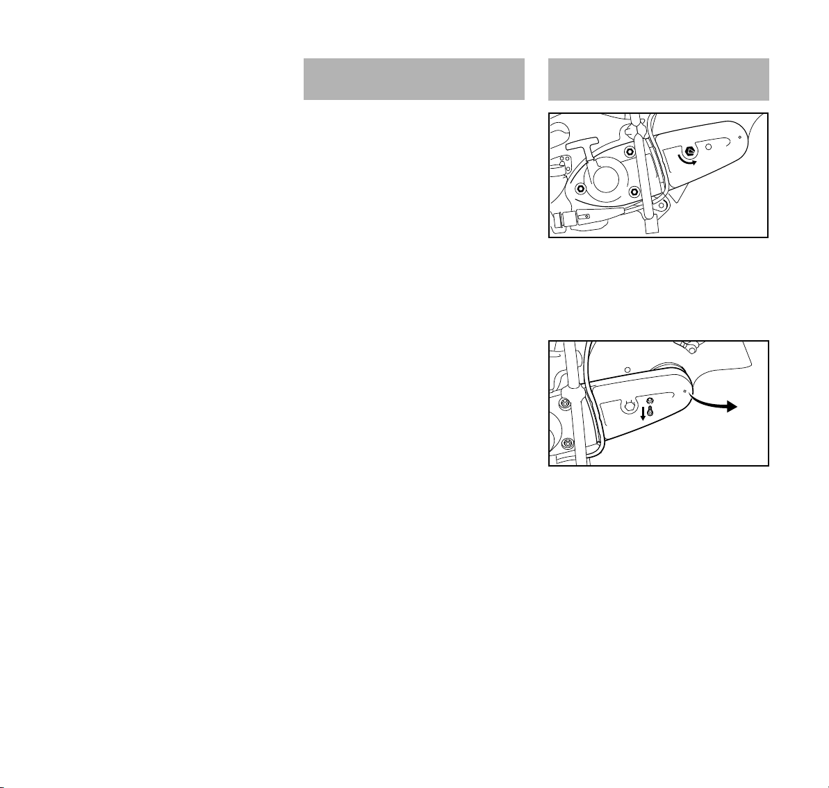
español / EE.UU
1
1
1
2
370BA037 KN
0
4
3
370BA061 KN
N Presione el casquillo firmemente
sobre la bujía
N Coloque la tapa en el casquillo de la
bujía y atorníllela
Dispositivo de arranque Sustitución de la correa
trapezoidal
Para prolongar la vida útil de la cuerda
de arranque, siempre observe los
puntos siguientes:
N Tire de la cuerda de arranque
solamente en el sentido
especificado.
N No tire de la cuerda sobre el borde
del buje guía.
N No tire de la cuerda más de lo
especificado.
N No deje que el mango de arranque
retroceda bruscamente, guíelo
lentamente hacia el interior de la
caja – vea el capítulo
"Arranque/Parada del motor."
Pida que el concesionario de servicio
sustituya la cuerda de arranque dañada
oportunamente. STIHL recomienda que
un concesionario STIHL autorizado
efectúe los trabajos de mantenimiento y
reparación.
N Afloje las tuercas (1)
N Gire la tuerca tensora (2) en sentido
contrahorario con la llave
combinada – aprox. 1/4 de vuelta,
hasta que tope = 0
N Extraiga la manguera de agua fuera
de la guía en el protector de la
correa trapezoidal
N Quite el tornillo (3)
N Eleve un poco el protector de la
correa trapezoidal (4) y extráigalo
hacia adelante
N Saque la correa trapezoidal de la
polea delantera
94
TS 410, TS 420
Page 97
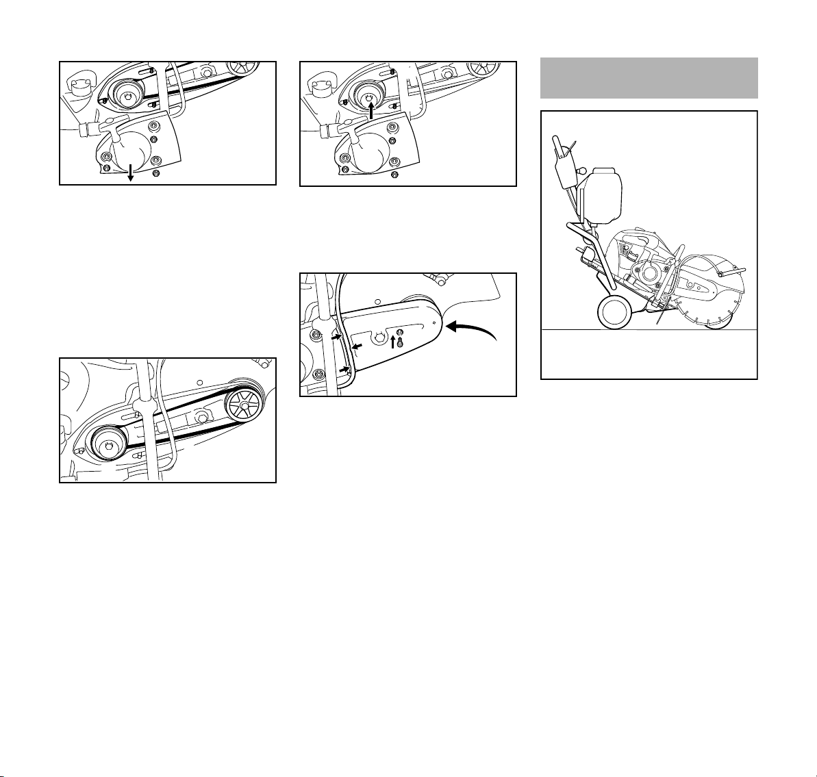
6
370BA062 KN
1
5
1
1
7
8
370BA063 KN
9
10
1
10
10
370BA064 KN
1
5
1
4
3
370BA065 KN
Carro para sierra
1307BA027 KN
español / EE.UU
N Destornille las tuercas (1)
N Quite la cubierta del arrancador (5)
N No quite el "brazo fundido con
protector" (6) – reténgalo en su
lugar en los espárragos hasta que
se coloque en su lugar la cubierta
del arrancador
N Quite la correa trapezoidal
defectuosa
N Coloque cuidadosamente la correa
trapezoidal (7) nueva en la polea de
la correa trapezoidal (8) en el motor
y en la polea delantera de la correa
trapezoidal (9)
INDICACIÓN
Debe ser posible desplazar suavemente
la correa.
N Instale la cubierta del
arrancador (5) sobre los
espárragos (10)
N Apriete las tuercas (1) con la mano
N Empuje el protector de la correa
trapezoidal (4) en su lugar
N Atornille el perno (3) y apriételo
N Introduzca la manguera de agua del
grifo de corte en la guía en el
protector de la correa trapezoidal
(flecha) hacia el protector - evite
radios de curvatura aguda
Proceda de la manera indicada en el
capítulo "Tensado de la correa
trapezoidal".
Al ejecutar unos pocos trabajos fáciles,
la tronzadora puede instalarse en un
carrito STIHL FW 20 (accesorio
especial) con unos cuantos pasos
fáciles.
El carrito para tronzadora lo hace fácil
– reparar el pavimento dañado de
calzadas para vehículos
– aplicar marcas en las calzadas para
vehículos
– cortar juntas de expansión.
TS 410, TS 420
95
Page 98

español / EE.UU
Almacenamiento de la
máquina
Si la máquina va a ser fuera de servicio
por aprox. 3 meses ó más
N Vacíe y limpie el tanque de
combustible en una zona bien
ventilada
N Deseche el combustible de acuerdo
con los reglamentos y teniendo en
mente el cuidado del medio
ambiente
N Haga funcionar el motor hasta que
el carburador se seque - esto ayuda
a evitar que los diafragmas del
carburador se peguen juntos
N Retire el disco abrasivo
N Limpie a fondo la máquina
N Almacene la máquina en un lugar
seguro y seco. Proteja contra el uso
desautorizado (por ejemplo, por los
niños)
96
TS 410, TS 420
Page 99

Información para mantenimiento
español / EE.UU
Los intervalos de mantenimiento dados a continuación corresponden a condicio
nes normales de trabajo. Los intervalos especificados deberán acortarse de modo
correspondiente si se trabaja por lapsos más largos que lo normal o bajo condicio
nes difíciles de corte (polvo excesivo, etc.).
Inspección visual (condición general,
Máquina completa
Controles de funcionamiento Comprobar el funcionamiento XX
Bomba de combustible manual (si la tiene)
Recogedor en el tanque de combustible
Depósito de combustible Limpiar X
Correa trapezoidal corrugada
Filtro de aire (todos sus componentes) Reemplazar Solamente si hay una pérdida notable de la potencia del motor
Aberturas de admisión de aire de
enfriamiento
Aletas del cilindro
Chispero en silenciador
Accesorio para agua
Carburador
2)
fugas)
Limpiar X
Revisar X
Solicite al concesionario especializado
su reparación
probar, revisar X
Reemplazar XXX
Limpiar / volver a tensar XX
Reemplazar XX
Limpiar X
Solicite al concesionario especializado
su limpieza
probar, revisar X
Limpiar o reemplazar X
probar, revisar xx
Solicite al concesionario especializado
su mantenimiento
Comprobar el ajuste de marcha en
vacío – el disco abrasivo no debe girar
Volver a ajustar la velocidad de mar
cha en vacío
1)
1)
1)
-
-
antes de comenzar el trabajo
al final del trabajo y/o
diariamente
Al volver a cargar el tanque
con combustible
XX
XX
-
Semanalmente
Mensualmente
Anualmente
si no funciona de modo
adecuado
Si tiene daños
X
X
x
Según se requiera
X
TS 410, TS 420
97
Page 100

español / EE.UU
Los intervalos de mantenimiento dados a continuación corresponden a condicio
nes normales de trabajo. Los intervalos especificados deberán acortarse de modo
correspondiente si se trabaja por lapsos más largos que lo normal o bajo condicio
nes difíciles de corte (polvo excesivo, etc.).
Ajustar la distancia entre electrodos X
Bujía
Todos los tornillos, tuercas y pernos acce
sibles (salvo los tornillos de ajuste)
Elementos antivibración
Disco abrasivo
Soportes/amortiguadores de caucho
(debajo de la máquina)
Etiquetas de advertencia Reemplazar X
1)
STIHL recomienda acudir a un concesionario STIHL especializado
2)
sólo disponible en algunos países
Cambiar después de cada 100 horas
de funcionamiento
-
Volver a apretar XX
probar, revisar XXX
Solicite al concesionario especializado
su sustitución
probar, revisar XX
Reemplazar XX
probar, revisar X
Reemplazar XX
1)
-
-
antes de comenzar el trabajo
al final del trabajo y/o
diariamente
Al volver a cargar el tanque
con combustible
Semanalmente
Mensualmente
Anualmente
si no funciona de modo
adecuado
X
Si tiene daños
Según se requiera
98
TS 410, TS 420
 Loading...