

Page 1

Page 2

&RQWHQWV
Main Parts of the TS 350 Cutquik
TM
Definitions 3
Safety precautions 4
The operator 4
- The cut-off machine 6
- The use of the cut-off machine 7
- Maintenance, repair and storing
of the cut-off machine 13
Storing the Machine 14
Mounting the Arbor Bearing
and Guard 15
Tensioning the V-belt 16
Abrasive Wheels 17
Limiting Adjustment on
Abrasive Wheel Guard 17
Mounting the Abrasive Wheel 18
Fuel mix 19
Fueling 19
2
Starting 20
Checking Spark Plug 22
General Notes on Operation 22
Air filter 23
Adjusting Carburetor 24
Motor Management 24
Rewind Starter 25
Changing the V-belt 27
STIHL Cutquik
TM
Cart 28
Spark arresting screen
in the muffler 28
Maintenance chart 29
Specifications 30
Andreas Stihl Limited Warranty
Federal Emission Control Systems
Utility Engines 31
This Manual contains operating and
safety instructions for your STIHL
TS 350 Cutquik
TM
Pay special attention to the safety
precautions outlined on pages 4 to 14.
Allow only persons who understand this
Manual to operate your cut-off machine.
To receive maximum performance and
satisfaction from your STIHL cut-off machine, it is important that you read and
understand the maintenance and
safety precautions before using your
cut-off machine. Contact your STIHL
dealer or the STIHL distributor for your
area if you do not understand any of the
instructions in this Manual.
Because a cut-off machine is a highspeed cutting tool, some special safety
precautions must be observed as with
any other cut-off machine to reduce the
risk of personal injury. Careless or
improper use may cause serious or
even fatal injury.
STlHL’s philosophy is to continually
improve all of its products. As a result,
engineering changes and improvements
are made from time-to-time.
If the operating characteristics or the
appearance of your cut-off machine
differs from those described in this
Manual, please contact your STIHL
dealer for information and assistance.
Printed on chlorine-free paper.
Printing inks contain vegetable oils,
paper is recyclable
1999 Andreas Stihl AG & Co, Waiblingen
0458 330 3021. M6. H9. T. Printed in Germany
76
Page 3

Main Parts of the TS 350 Cutquik
TM
2 TS 350
Page 4

'HILQLWLRQV
$EUDVLYH:KHHO
Can either be an abrasive wheel
or a diamond abrasive wheel.
:KHHO*XDUG
Guards the wheel and deflects sparks.
$GMXVWLQJ/HYHURI:KHHO*XDUG
For adjusting the wheel guard in a
way that the beam of sparks is
directed away from the operator
and the machine.
)URQW+DQGOH
Handle bar for the left hand
at front of cut-off machine.
0XIIOHU
Reduces engine exhaust noise
and directs the exhaustgases
6SDUN3OXJ%RRW
Connects the spark plug
with the ignition wire.
7KUXVW:DVKHU
Distributes claming pressure of
mounting nut evenly over abrasive wheel.
6WDUWHU*ULS
The grip of the pull starter
which is the device to start the engine.
6WRS6ZLWFK
Switches the engine’s ignition system
off and stops the engine.
)XHO)LOOHU&DS
For closing the fuel tank.
(Fits on fuel filler neck).
:LQJ1XWVRI)LOWHU&RYHU
For removing filter cover to permit
filter to be cleaned.
$LU)LOWHU
Prevents dust and foreign
matter from entering the carburetor.
(Not illustrated)
7KURWWOH7ULJJHU,QWHUORFN
Must be depressed before activating
the throttle trigger.
6WDUWLQJ7KURWWOH/RFN
Keeps the throttle partially open
during starting.
(FFHQWULF$GMXVWHU
For tensioning the V-belt.
&OXWFK
Couples engine to the V-belt pulley
when engine is accelerated beyond
idle speed.
(Not illustrated)
9%HOW3XOOH\
The wheel that drives the V-belt
and the abrasive wheel.
(Not illustrated)
5HDU+DQGOH
The support handle for the right hand,
located at or toward the rear of the
cut-off machine.
76
&KRNH/HYHU
A control used when starting cold
engine
7KURWWOH7ULJJHU
Controls the speed of the engine.
1RWH
Different models may have different
parts and controls.
Page 5

6DIHW\3UHFDXWLRQV
The use of any cut-off
machine may be
hazardous. Because a
cut-off machine is a
high-speed, fast-cutting
power tool, special safety precautions
must be observed to reduce the risk of
personal injury and fire.
It is important that you read, fully understand and observe the following safety
precautions and warnings.
Read the Owner’s
Manual and the safety
instructions periodically.
Careless or improper use of any
cut-off machine may cause serious or
fatal injury.
Have your STIHL dealer show you
how to operate your cut-off machine.
Observe all applicable local safety
regulations, standards and ordinances.
:DUQLQJ
Minors should never be allowed to use a
cut-off machine. Bystanders, especially
children and animals should not be
allowed in the area where a cut-off
machine is in use. Never let the cut-off
machine run unattended.
Do not lend or rent your cut-off machine
without the Owner’s Manual. Be sure
that anyone using your cut-off machine
understands the information contained
in this manual. Employers should establish a training program for operators of
gasoline powered, hand held portable,
cutt-off machines to assure safe operation of these machines. These safety
precautions and warnings apply to the
use of all STIHL Cutquiks
Different models may have different
parts and controls. See the appropriate
section of your owner’s manual for a
description of the controls and function
of the parts of your model cut-off
machine.
Safe use of a cut-off machine involves
- the operator
- the cut-off machine
- the use of the cut-off machine.
7+(23(5$725
3K\VLFDO&RQGLWLRQ
You must be in good physical condition
and mental health and not under the
influence of any substance (drugs.
alcohol, etc.) which might impair vision,
dexterity or judgement. Do not operate a
cut-off machine when you are fatigued.
Be alert - if you get tired while operating
your cut-off machine, take a break, tiredness may result in loss of control.
Working with any cut-off machine can be
strenuous. If you have any condition that
might be aggravated by strenuous work,
check with your doctor before operating
a cut-off machine.
TM
.
:DUQLQJ
Prolonged use of cut-off machines (or
other machines) exposing the operator
to vibrations may produce whitefinger
disease (Raynaud’s phenomenon) or
carpal tunnel syndrome. These
conditions reduce the hand’s ability to
feel and regulate temperature, produces
numbness and burning sensations and
cause nerve and circulation damage and
tissue necrosis. All factors which contribute to whitefinger disease are not
known, but cold weather, smoking and
diseases or physical conditions that
affect blood vessels and blood transport,
as well as high vibration levels and long
periods of exposure to vibration are
mentioned as factors in the development
of whitefinger disease. In order to
reduce the risk of whitefinger disease
and carpal tunnel syndrome, please
note the following:
- Most STIHL cut-off machine models
are available with an anti-vibration
("AV") system designed to reduce
the transmission of vibrations
created by the engine to the
operator’s hands. An AV system is
recommended for those persons
using cut-off machines on a regular
or sustained basis.
- Wear gloves and keep your hands
warm.
- Keep the AV system well maintained.
A cut-off machine with loose
components or with damaged or
76
Page 6

worn AV buffers will tend to have
higher vibration levels.
- Maintain a firm grip at all times, but
do not squeeze the handles with
constant, excessive pressures, take
frequent breaks.
All the above mentioned precautions do
not guarantee that you will not sustain
whitefinger disease or carpal tunnel
syndrome. Therefore continual and
regular users should monitor closely the
condition of their hands and fingers.
If any of the above symptoms appear,
seek medical advice immediately.
3URSHU&ORWKLQJ
Clothing must be sturdy
and snug-fitting, but allow
complete freedom of
movement. Avoid loose-
fitting jackets, scarfs,
neckties, jewelry, flared or cuffed pants,
unconfined long hair or anything that
could become caught on any obstacles
or moving parts of the unit. Wear overalls or long pants to protect your legs.
Do not wear shorts.
:DUQLQJ
When cutting metal, a cut-off machine
generates sparks which can ignite
clothing. Most fabrics used in clothing
are flammable - even flame retardant
fabrics will ignite at higher temperatures.
To reduce the risk of burn injury STIHL
recommends wearing clothing made of
leather, wool, flame-retardant treated
cotton or a tightly woven, heavier cotton
such as denim. Some flame-retardant
synthetic fabrics are also suitable but
others such as polyester, nylon, rayon
and acetate can melt during fire into a
tar-like matter that burns into the skin.
Keep clothing free of oil, fuel, grease
and other flammable substances.
Protect your hands with
gloves when handling the
cut-off machine.
Heavy-duty, nonslip
gloves improve your grip
and protect your hands.
Good footing is most important in cut-off machine
work.
Wear sturdy boots with
nonslip soles. Steel-toed
safety boots are recommended.
:DUQLQJ
Loose objects may be thrown toward the
operator by the cutting tool.
To reduce the risk of
injury to your eyes never
operate a cut-off machine
unless wearing goggles
or properly fitted safety
glasses with adequate top and side
protection complying with ANSI Z 87.1.
Proper eye protection is a must.
Wear an approved safety hard hat to
protect your head. cut-off machine noise
may damage your hearing.
Always wear sound barriers (ear plugs
or ear mufflers) to protect your hearing.
Regular users should have their hearing
checked regularly.
:DUQLQJ
Use of this product to cut
masonry, concrete, metal
and other materials can
generate dust, mists and
fumes containing
chemicals known to cause serious or
fatal injury or illness, such as respiratory
disease, cancer, birth defects or other
reproductive harm. If you are unfamiliar
with the risks associated with the particular material being cut, review the material
safety data sheet and/or consult your
employer, the material manufacturer/supplier, governmental agencies such
as OSHA and NIOSH and other sources
on hazardous materials. California and
some other authorities, for instance,
have published lists of substances
known to cause cancer, reproductive
toxicity, etc.
Control dust, mist and fumes at the
source where possible. In this regard
use good work practices and follow the
recommendations of the manufacturer/supplier, OSHA/NIOSH, and occupational and trade associations. A water
attachment kit is available for your cut-off
machine and should be used for dust
suppression when wet cutting is feasible.
When the inhalation of dust, mists and
fumes cannot be eliminated, the operator
76
Page 7

and any bystanders should always wear
a respirator approved by NIOSH/MSHA
for the material being cut.
:DUQLQJ
Cutting masonry, concrete and other
materials with silica in their composition
may give off dust containing crystalline
silica. Silica is a basic component of
sand, quartz, brick clay, granite and
numerous other minerals and rocks.
Repeated and/or substantial inhalation
of airborne crystalline silica can cause
serious or fatal respiratory diseases,
including silicosis. In addition, California
and some other authorities have listed
respirable crystalline silica as a substance known to cause cancer. When
cutting such materials, always follow the
respiratory precautions mentioned
above.
:DUQLQJ
Breathing asbestos dust is dangerous
and can cause severe or fatal injury,
respiratory illness or cancer. The use
and disposal of asbestos-containing
products have been strictly regulated by
OSHA and the Environmental Protection
Agency. Do not use your cutting-off
machine to cut or disturb asbestos,
asbestos-containing products, or products such as pipes which are wrapped
or covered with asbestos insulation. If
you have any reason to believe that you
might be cutting asbestos, immediately
contact your employer or a local OSHA
representative.
7+(&872))0$&+,1(
Parts of the cut-off machine, illustrations
and definitions of the parts see pages
2 and 3.
:DUQLQJ
Never modify a cut-off machine in any
way. Only attachments supplied by
STIHL or expressly approved by STIHL
for use with the specific STIHL cut-off
machine models are authorized.
Although certain unauthorized attachments are useable with the STIHL
powerhead, their use may, in fact be
extremely dangerous.
:DUQLQJ
Dust may collect on the powerhead,
especially around the carburetor and
may collect gasoline resulting in danger
of fire. Clean dust from the powerhead
regularly.
$EUDVLYHZKHHOV
:DUQLQJ
Before assembling your cutting wheel
make sure that the maximum operating
wheel speed is above or equal to the
spindle speed of your cut-off machine as
provided in the Specifications of this
manual.
Abrasive wheels for free-hand cutting
are subjected to particularly high
bending and compressive stresses.
:DUQLQJ
Unauthorized wheels may shatter or
break. Use only STIHL wheels or other
authorized wheels with approved RPM
ratings.
Inspect the abrasive
wheel frequently and
replace immediately if the
abrasive wheel is cracked
or warped. Cracked or
warped wheels may shatter or break
and cause serious personal injury.
Out-of-round or unbalanced abrasive
wheels increase vibration and reduce
the service life of the cut-off machine.
Use STIHL wheels approved for this unit.
Abrasive wheels are heat sensitive.
Always store your cut-off machine in a
place where the cutting wheel is not
exposed to direct sunlight or other
sources of heat. Store spare cutting
wheels in a dry place where there is no
risk of frost damage. Failure to follow
these directions may cause the wheel to
shatter or crack in use causing serious
or fatal injury.
76
Page 8

:DUQLQJ
Never use carbide-tipped, wood-cutting
or circular saw blades. They can cause
severe personal injury from reactive
forces, blade contact or thrown objects.
Your STIHL dealer stocks a range of
special abrasive wheels for the many
applications of the cut-off machine.
:DUQLQJ
Use of the wrong abrasive wheel or
material for which it was not designed
may cause that wheel to shatter causing
serious or fatal injury.
Only use the abrasive wheel approved
for the type of material to be cut. There
are different abrasive wheels each
specially marked, for example:
1. Stone
Also can be used for concrete,
masonary, reinforced concrete
and brick cutting.
2. Steel
Can be used for all ferrous metal
cutting.
3. Asphalt
Also can be used for aggregate
concrete cutting.
4. Ductile iron
Also can be used for certain grades
of cast iron (SG 17-24), bronze and
copper cutting.
For cutting composite materials please
ask your STIHL dealer.
'LDPRQGDEUDVLYHZKHHOV
Diamond abrasive wheels have a much
better cutting performance than the
abrasive wheels. The wheels are steel
centered and diamond particles are
imbedded in their cutting edges.
They can be used for concrete, asphalt,
natural stone, clay pipe, brick and the
like.
They are not suitable for cutting metal or
other materials.
Wet or dry cutting is possible. With wet
cutting you get a longer life of your
wheel. Water attachments are available
for your STIHL cut-off machine.
See the appropriate section of your
owner’s manual.
:DUQLQJ
Do not remount a used diamond
abrasive wheel without first inspecting
for under-cutting, flatness, core fatigue,
segment damage or loss, signs of
overheating (discoloration) and possible
arbor hole damage.
Check the wheel for cracks and make
sure that no pieces have broken off the
wheel before use.
Always fit the wheel so that the arrow on
the wheel points in direction of the
rotation of the spindle.
7+(86(2)7+(&872))0$&+,1(
7UDQVSRUWLQJWKH&XWTXLN
:DUQLQJ
Always stop the engine before putting a
cut-off machine down or carrying it. The
abrasive wheel continues to rotate for a
short while after the throttle trigger is
released (flywheel effect). Carrying a
cut-off machine with the engine running
is extremly dangerous. Accidental
acceleration of the engine can cause the
wheel to rotate. Avoid touching the hot
muffler.
By hand: When carrying your cut-off
machine by hand, the engine must be
stopped and the cut-off machine must
be in the proper position. Grip the front
handle and place the muffler at the side
away from the body.
:DUQLQJ
Always protect the cutting wheel from
hitting the ground or any other objects.
Damaged wheels may shatter and
cause serious or fatal injury.
%\YHKLFOHProperly secure your
cut-off machine to prevent turnover, fuel
spillage and damage to the cut-off
machine.
1HYHUWUDQVSRUWZLWKFXWWLQJZKHHO
PRXQWHG
70
76
Page 9

A wheel damaged during transportation
may shatter during operation and cause
serious personal injury.
3UHSDUDWLRQIRUWKHXVHRIWKH
FXWRIIPDFKLQH
For assembly, follow the procedure
described at the appropriate section of
your owner’s manual.
Before operation of your cut-off machine
be sure the controls (e.g. throttle trigger,
stop switch.) and the safety devices are
working properly, the carburetor idle and
maximum speed are correctly adjusted,
and the wheel guard is in place and
securely fastened to your unit.
All wheels should be carefully inspected
for good condition before mounting.
Adjust the wheel guard so
that sparks, dust and cut
material are deflected
away from the operator,
and cannot reach
flammable surroundings. See operating
instructions of your owner’s manual.
Never operate a cut-off machine that is
damaged, improperly adjusted or not
completely and securely assembled.
Inspect for safety in operation.
Proper tension of the V-belt is important.
In order to avoid a false setting the
tensioning procedure must be followed
as described in your Manual. Always
make sure the hexagonal collar nuts for
the cast arm are tightened securely.
Check V-belt tension after one hour of
operation and correct if necessary.
:DUQLQJ
IRU76DQG76RQO\
The STIHL TS 350 and TS 360
TM
Cutquik
elbow connector to facilitate easier
refueling. Always keep the connector
and fuel filler cap tightened and properly
sealed. A loose or improperly seated
connector or cap may vibrate loose
during operation causing fuel spillage
which may result in a fire which can
cause serious or fatal injury. Never
operate the unit with a cracked, broken
or improperly seated or adjusted filler
neck. This could permit fuel leakage and
lead to fire. Do not fill tank above the
threefourths level of the neck entry
diameter into the tank. Do not fill tank
above the "max" line on the fuel filler
elbow. Overfilling reduces the room in
the tank for fuel expansion and may lead
to fuel spillage through the tank vent and
risk of fire.
)XHOLQJ
Your STIHL cut-off machine uses an
oil-gasoline mixture for fuel (see chapter
"Fuel" of your owner’s manual).
is supplied with a fuel filler
:DUQLQJ
Gasoline is an extremely
flammable fuel. If spilled or
ignited by a spark or other
ignition source, it can cause
fire and serious burn injury
or property damage. Use extreme caution when handling gasoline or fuel mix.
Do not smoke or bring any fire or flame
near the fuel.
)XHOLQJ,QVWUXFWLRQV
Fuel your cut-off machine in well-ventilated areas, outdoors only.
Always shut off the engine and allow it to
cool before refueling. Relieve fuel tank
pressure by loosening the fuel cap
slowly.
Select bare ground for fueling and move
at least 10 feet (3 m) from fueling spot
before starting the engine. Wipe off any
spilled fuel and check for leakage.
:DUQLQJ
If fuel gets spilled on clothes, especially
trousers, it is very important to change
clothes immediately. Do not rely upon
evaporation. Flammable quantities of
fuel may remain on clothes after a spill
for longer than expected. Cutting metal
with cut-off machine when clothes are
wet or damp from gasoline is extremely
dangerous as the operator’s clothes
76
Page 10
might catch fire and cause serious or
fatal injury.
Always make sure that the fuel cap is
tightened securely. Check for fuel
leakage while refueling and during
operation. If a fuel leak is suspected,
do not start or run the engine until leak is
fixed and spilled fuel has been wiped
away.
Do not allow the grip to snap back, but
guide the starter rope slowly back to
permit the rope to rewind properly.
Failure to follow this procedure may
result in injuries to hand or fingers and
may damage the starter mechanism.
Always stop the engine and be sure the
wheel has stopped rotating before
setting down the cut-off machine.
:DUQLQJ
Unit vibrations can
cause an improperly
tightened fuel cap to
loosen or come off and
spill quantities of fuel.
In order to reduce risk of fuel spillage
and fire, tighten fuel cap by hand with as
much force as possible.
The screw driver end of the STIHL
combination wrench or other similar tool
can be used as an aid in tightening
slotted fuel caps.
6WDUWLQJ
:DUQLQJ
Your cut-off machine is a one-person
tool. Do not allow otherpersons to be
near the cut-off machine. Start and
operate your cut-off machine without
assistance. For specific starting instructions, see the appropriate section of your
owner’s manual.
Do not drop start. This method is very
dangerous because you may loose
control of the cut-off machine.
Place the cut-off machine on firm ground
or other solid surface in an open area.
Maintain a good balance and secure
footing. Be absolutely sure that the
cutting wheel is clear of you and all other
obstructions and objects, including the
ground; because when the engine starts
at starting-throttle, engine speed will be
fast enough for the clutch to engage
V-belt pulley and turn the wheel. Never
attempt to start the cut-off machine
when the abrasive wheel is in a cut.
When you pull the starter grip, don’t
wrap the starter rope around your hands.
:RUNLQJ&RQGLWLRQV
Operate the cut-off machine under good
visibility and daylight conditions only.
002BA058 KN
:DUQLQJ
Your cut-off machine
produces poisonous
exhaust fumes as soon
as the combustible
engine is running. These
gases (e.g. carbon monoxide) may be
colorless and odorless.
To reduce the risk of serious or fatal
injury from breathing toxic fumes, never
run the cut-off machine indoors or in
poorly ventilated locations. Ensure
proper ventilation when working in
trenches or other confined areas.
76
Page 11

002BA060 KN
002BA059 KN
002BA061 KN
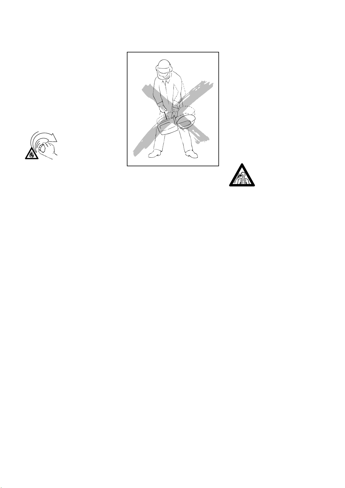
Never use the cut-off machine with one
hand. Your STIHL cut-off machine is
designed for hand-held use or operation
on a cut-off machine cart. Cutting with
your cut-off machine resting on the
ground or other surface can cause
excessive wear to the bracket designed
to protect the bottom of the tank
housing. Loss of fuel and personal injury
from fire may result. Replace damaged
or badly worn brackets immediately.
Grip: Always hold the cut-off machine
firmly with both hands when the engine
is running. Place your left hand on front
handle bar and your right hand on rear
handle and throttle trigger.
Left-handed users should follow this
instruction too.
Wrap your fingers tightly around the
handles, keeping the handles cradled
between your thumbs and forefingers.
Make sure your cut-off machine handles
and grip are in good condition and free
of moisture, pitch, oil or grease.
Avoid standing in direct line with the
wheel.
:DUQLQJ
Take extreme care in wet and freezing
weather (rain, snow, ice). Clear the area
where you are working.
:DUQLQJ
Avoid stumbling on obstacles and watch
out for holes or ditches. Be extremely
cautious when working on slopes or
uneven ground.
:DUQLQJ
Never operate the cut-off machine with
the starting-throttle lock engaged as this
does not permit proper control of the
speed of the unit and may lead to
serious injury.
:DUQLQJ
Sparks from cutting metal
can burn or cause cloth-
ing to catch fire. Don’t use
a cut-off machine on flammable ground. Always direct sparks
away from the operator or any flammable surroundings.
:DUQLQJ
To reduce the risk of injury from fire,
do not cut into any pipe, drum or other
container without first insuring that it
does not contain volatile or flammable
substance.
2SHUDWLQJ,QVWUXFWLRQV
:DUQLQJ
The wheel guard is adjustable. It is
extremely important that the wheel
guard is in place and set to suit the type
of work and your stance. The guard
should always be adjusted so that the
user is not endangered by particles of
the material being cut, sparks or pieces
of damaged wheels either directly or by
76
Page 12

ricochet. Failure to follow this instruction
could result in serious or fatal injury.
The ideal working speed of the cut-off
machine depends on many factors, e. g.,
the material being cut, the type and
quality of the cutting wheel.
It is essential to determine the direction
of the cut exactly before applying the
abrasive wheel to the work. Wheels are
constructed for UDGLDOpressure only.
/DWHUDO pressure must be avoided.
Check for cracks and make sure that no
pieces have broken off from the wheel
when it is stopped.
Check the wheel guard for cracks. If you
discover any cracks, fit a new guard.
:DUQLQJ
Hold the cut-off machine steady. Do not
change the direction of the cut during
the cut as this may produce a high
torsional load on the abrasive wheel and
may cause it to break or shatter.
To achieve a clean and efficient cut, pull
the abrasive wheel across the work or
move it "to and fro" in the cutting
direction. Do not use force to push the
abrasive wheel into the work.
Insert the wheel into the material only as
deep as necessary to make the cut.
To reduce the amount of dust created,
do not cut all the way through stone and
concrete materials - leave a thin piece
uncut. For most such materials, this
piece can be easily broken afterwards.
Do not cock, jam or wedge the wheel in
the cut.
:DUQLQJ
Do not use abrasive wheels for rough
grinding. Large bending stresses occur
during such work and abrasive wheels
may shatter or break and could cause
serious or fatal injury.
If a cut-off machine cart is used, sweep
debris from the path of the wheels as
such may cause flexing of the abrasive
wheel. This would result in high frictional
forces and thus greatly reduce the
engine power available for the actual
cutting work.
Always use the cart to cut in a straight
line.
:HWFXWWLQJZLWKDEUDVLYHZKHHOV
When cutting masonry with a water
attachment:
1. Make certain water does not flow on
wheel that is not running, since the
wheel will absorb water and that will
affect wheel balance.
2. Shut water off before wheel stops
so that excess water will be
dissipated.
3. Be certain water is applied to both
sides of wheel, since uneven
distribution can cause "one sided"
wear with possible wheel breakage.
4. Use these wheels up the same day.
Do not store and reuse a wheel that
has been used with water.
,PSRUWDQW$GMXVWPHQWV
At correct idle speed, wheel should not
turn. For direction to adjust idle speed,
see the appropriate section of your
owner’s manual.
Do not use a cut-off machine with incorrect idle speed adjustment. The rotating
wheel may cause injury.
Have your STIHL dealer check your
cut-off machine and make proper
adjustments or repairs.
Never touch a rotating wheel with your
hand or any part of your body.
5HDFWLYHIRUFHV
:DUQLQJ
Reactive forces may occur at any time
the cutting wheel on at cut-off machine
is rotating. If the wheel is slowed or
stopped by frictional contact with any
solid object or by a pinch, reactive forces
may occur instantly and with great force.
76
Page 13

These reactive forces may result in the
operator losing control of the cut-off
machine, which may, in turn, result in
serious or fatal injury.
An understanding of the causes of these
reactive forces may help you avoid loss
of control. Reactive forces are exerted in
a direction opposite to the direction in
which the wheel is moving at the point of
contact or pinch.
Pull-away, climbing and rotational
forces.
The most common reactive forces are
pull-away and climbing. If the contact is
at the bottom of the wheel, a cut-off
machine will try to pull away from the
operator (pull-away). If the contact is at
the front of the wheel, the wheel may
attempt to climb the object being cut
(climbing). If the wheel is severely
pinched at the front, the wheel may be
instantly thrown up and back towards
the operator with a great force in a
rotational motion. The greater the force
generated, the more difficult it will be for
the operator to control the cut-off
machine. Any of the reactive forces can,
in some circumstances, cause the
operator to lose control of a cut-off
machine, allowing the rotating wheel to
come into contact with the operator.
Severe personal injury or death can
result.
Use only cutting attachment authorized
by STIHL. 1HYHUuse chipped abrasive
wheels, circular saw blades, carbide
tipped blades, rescue blades or woodabrasive or toothed blades of any nature
on a cut-off machine. The use of such
wheels or blades will greatly increase
the risk of loss of control and severe
personal injury or death from reactive
forces, since the chipped section of an
abrasive wheel, or the teeth of a saw
blade may catch in the material being
cut and generate substantially greater
reactive forces.
Cut-off machines are designed for use
with abrasive wheels in good condition
RQO\Machines designed for use with
wood-abrasive or other toothed blades
use different types of guarding systems
which provide the protection neccessary
for those types of blades. Machines,
such as a cut-off machine, which are
designed for use with abrasive wheels,
require a different guarding system
which is not designed to provide protection against all dangers presented by
circular saw blades, carbide-tipped
blades, rescue blades or wood-abrasive
or toothed blades of any nature.
:DUQLQJ
To reduce the risk of injury from loss of
control or from the shattering of an
abrasive wheel:
1. Hold the cut-off machine firmly with
both hands.
2. Maintain good balance and footing at
all times. Never cut while standing
on a ladder.
3. Do not exceed the maximum
operating speed marked on the
wheel.
4. Do not use a wheel that has been
dropped.
5. Never use circular saw blades,
carbide-tipped blades, rescue
blades, wood-abrasive blades or
toothed blades of any nature. Their
use increases the risk of injury from
reactive forces, blade contact and
thrown tips.
6. Do not cut any material for which the
abrasive wheel is not authorized.
7. Position the cut-off machine in such
a way that your body is clear of the
abrasive attachment.
8. Begin abrasive and continue at full
throttle.
9. Do not overreach.
76
Page 14

15. Be alert to shifting of the work piece
or anything that could cause the cut
to close and pinch the wheel.
Follow the maintenance and repair
instructions in the appropriate section of
your owner’s manual.
10. Do not cut above shoulder height.
11. Use your cut-off machine for abrasive
only. It is not designed for prying or
shoveling away any objects.
12. Do not grind on side of the abrasive
wheel.
13. Do not twist, thrust, knock or drop the
machine. This can cause damage
to the wheel.
14. Be especially alert for reactive forces
when abrasive with the front of the
wheel.
16. Release the pressure on the
cut-off machine as you reach the
end of the cut. Too much pressure
may cause the operator to lose
control of the cut-off machine when
the abrasive wheel completes the
cut. The abrasive wheel may contact the operator or strike some
foreign object and shatter.
17. Use extreme caution when
re-entering a cut and do not turn
the wheel at an angle or push the
002BA062 KN
wheel into the cut as this may result
in a pinching of the wheel.
0DLQWHQDQFH5HSDLUDQG6WRULQJ
RIWKH&XW2II0DFKLQH
0DLQWHQDQFHUHSODFHPHQWRUUHSDLU
RIWKHHPLVVLRQFRQWUROGHYLFHVDQG
V\VWHPVPD\EHSHUIRUPHGE\DQ\
QRQURDGHQJLQHUHSDLUHVWDEOLVKPHQW
RULQGLYLGXDO+RZHYHULI\RXFODLP
ZDUUDQW\IRUDFRPSRQHQWZKLFKKDV
QRWEHHQVHUYLFHGRUPDLQWDLQHGSUR
SHUO\RULIQRQDSSURYHGUHSODFHPHQW
SDUWVZHUHXVHG67,+/PD\GHQ\
ZDUUDQW\
Never operate a cut-off machine that is
damaged, improperly adjusted or not
completely or securely assembled.
Use only STIHL replacement parts for
maintenance and repair. Use of parts
manufactured by others may cause
serious or fatal injury.
:DUQLQJ
Always stop the engine and make sure
that the wheel is stopped before doing
any maintenance or repair work or
cleaning the cut-off machine. Do not
attempt any maintenance or repair work
not described in your owner’s manual.
Have such work performed at your
STIHL service shop only.
Clean grinding dust after finishing work.
Empty the fuel tank before storing for
longer than a few days.
Fuel may only be stored in correctly
labeled and approved containers.
Avoid direct skin contact and do not
in-hale the petrol vapours.
Keep the handles dry, clean and free of
oil and fuel.
Tighten all nuts, bolts and screws except
the carburetor adjustment screws after
each use.
76
Page 15

6WRULQJWKH0DFKLQH
:DUQLQJ
Never test the ignition system with
ignition wire terminal removed from
spark plug or with unseated spark plug,
since uncontained sparking may cause
a fire.
:DUQLQJ
To reduce the risk of fire and burn injury,
use only spark plugs authorized by
STIHL. Always press spark plug boot
snugly onto spark plug terminal of the
proper size. (Note: If terminal has
detachable SAE adapter nut, it must be
attached.) A loose connection between
spark plug terminal and ignition wire
connector in the boot may create arcing
that could ignite combustible fumes and
cause a fire. Keep spark plug clean, and
make sure ignition lead is in good
condition.
:DUQLQJ
Do not operate your cut-off machine if
the muffler is damaged, missing or modified. An improperly maintained muffler
will increase the risk of fire and hearing
loss.
your cut-off machine if the screen is
missing or damaged.
For any maintenance please refer to the
maintenance chart DQGWRWKHZDUUDQW\
VWDWHPHQW near the end of this manual.
Store spare wheels on a flat surface in a
dry place preferably at a constant
temperature where there is not risk of
frost, preferably at a constant
temperature. Store cut-off machine in a
high or locked place, away from children.
Do not store a cut-off machine with a
wheel mounted on the machine.
For periods of about 3 months or longer:
Drain and clean the fuel tank.
•
Run engine until carburetor is dry -
•
this helps prevent the carburetor
diaphragms sticking together.
Remove the abrasive wheel.
•
Thoroughly clean the machine -
•
pay special attention to the
cylinder fins and air filter.
Store the machine in a dry, high
•
or locked location - out of the
reach of children and other
unauthorized persons.
Never touch a hot muffler or spill fuel or
other flammable liquid over it. Burn injuries or fire will result. If your muffler was
equipped with a spark-arresting screen
to reduce the risk of fire (e. g. in the USA,
Canada and Australia), never operate
76
Page 16

Mounting the Arbor Bearing and Guard
The cutting blade drive (bearing with arbor and blade
guard) must be assembled before the machine is used for
the first time. The arbor bearing can be mounted to the
inboard or outboard side of the cast arm to suit cutting
requirements. Under normal circumstances the drive
should be mounted inboard of the arm because of the
better balance and only mounted outboard when required.
Inboard mounting
First fit V-belt (1) on the belt pulley (2) and position the
bearing plate (3) against the inside of the cast arm (4) so
that the tapped holes line up with the slots in the cast arm.
Position V-belt guard (5) against the outside of the arm
(4). Insert a hex. head screw (6) through one of the two
front holes and screw it into the bearing plate-move V-belt
guard to and fro to ease insertion. Now let go of the
bearing. Fit the other two screws (6) through the holes in
the V-belt guard (5) and screw them into the bearing plate
- the eccentric adjuster (7) must be fitted on the rear
screw.
Top: V-belt in position for inboard mounting
Center: Tightening hex. head screw
Bottom: V-belt in pos ition for outboard moun ting
Outboard mounting
Position the bearing plate (3) against the outside of the
arm (4) and fit the V-belt (1) on the belt pulley (2). If the
V-belt is new, this operation is easier if the M 10 hex. head
nut (8) is turned counterclockwise with the combination
wrench (17 mm), i.e. this turns the belt pulley (2). Position
bearing plate (3) so that the tapped holes line up with the
slots in the arm.
TS 350 15
Page 17

g
Tensioning the V-belt
Top: Inserting hex. head screw
Bottom: Bearin
mounted outboard
Fit the V-belt guard (5) on the inside of the arm. Insert a
hex. head screw (6) through one of the two front holes
and screw it into the bearing plate (3) - move V-belt guard
(5) to and fro to ease insertion. The assembly sequence is
otherwise as for "Inboard mounting".
Turning eccentric adjuster to tension V-belt
To tension the V-belt, first slacken off the two front hex.
head screws (6) and moderately tighten the rear one (with
eccentric adjuster). Then use a 13 mm open end wrench
to turn the eccentric adjuster (7) clockwise. This causes
the bearing to be shifted away from the engine and thus
tension the V-belt.
Once the correct tension has been reached, release the
eccentric adjuster (7) (as the rear hex. head screw has
been tightened down slightly the bearing and adjuster
remain in the set position). Then finally tighten down the
hex. head screws (6), starting with the rear one (with
eccentric adjuster).
The V-belt is correctly tensioned if it can be depressed
slightly (5-10 mm/
3
/16-3/8") with moderate thumb pressure.
Overtensioning of the V-belt will accelerate wear.
When the cutting wheel is mounted outboard the wheel
guard does not have the full 360° adjustment since the
movement of the adjusting lever is restricted by the
On a new machine, or if a new V-belt has been fitted, it is
advisable to check V-belt tension after about 1 operating
hour and correct it if necessary.
handlebar mounting, i. e. reduced by about 20°.
16 TS 350
Page 18

Abrasive Wheels
Cutting wheels for free-hand cutting operations are subjected to particularly high bending and compressive stresses. STIHL has therefore developed - together with leading abrasive wheel manufacturers - top quality cutting
blades which exactly match the engine characteristics of
the cut-off-saw. They are of a consistently high quality
and perfectly balanced.
Out-of-round or poorly balanced abrasive wheels
increase vibration and reduce the service life of the
cut-off-saw. Good abrasive performance can only be
achieved with the abrasive wheels supplied by STIHL.
Abrasive wheels are heat sensitive. Always store your
cutoff-saw in a place where it is not exposed to direct
sunlight or other sources of heat.
Store spare cutting wheels in a dry place where there is
no risk of frost, preferably at a constant temperature.
Limiting adjustment on abrasive wheel guard
Adjustment range of abrasive wheel guard
On the USA version a stop (1) is attached to the cut-offsaw's bearing plate.
The rubber buffer (2) of this stop projects through the
flange of the abrasive wheel guard so that its adjustment
is limited to the range shown (see illustration). This
prevents the guard being turned too far.
Your STIHL dealer stocks a range of special abrasive
wheels (3 and 6 mm / 0.12 and 0.24 in thick) for the manifold applications cut-off-saw. For example, wheels for
abrasive bituminous material, gravel asphalt, stone, concrete, clay pipe, structural steel, highly alloyed steel, cast
iron, non-ferrous metals etc.
It is necessary to take out the mounting screws (3) and
remove the rubber buffer (2) to turn the guard through
approx. 180° when the abrasive wheel is fitted on the outboard side of the cast arm. Then turn the guard to the
required position and refit the rubber buffer on the stop.
TS 350 17
Page 19

Mounting the abrasive Wheel
The engine must be switched off and the arbor blocked
before mounting or removing the abrasive wheel. To do
this, push the locking pin squarely through the hole in the
V-belt guard. If one of the V-belt pulley spokes is in the
way, use the combination wrench to turn the arbor until the
locking pin can be inserted.
Slacken off and remove the M 10 hex. head screw with the
combination wrench (17 mm) and take it off the arbor
together with the front thrust washer.
The cutting wheel can now be pulled off the arbor and
taken out of the guard. This operation is made easier if the
blade guard is turned so that its lower edge is vertical.
Before fitting the new abrasive wheel, check that the rear
thrust washer is positioned so that the notch in its center
hole engages over the lug on the arbor.
Mount the new abrasive wheel in the reverse sequence to
that described above. Make sure that the locking tab on
the front thrust washer engages in one of the two slots in
the arbor. Use combination wrench to securely tighten the
M 10 hex. head screw.
Top: Blocking the arbor
Center: Removing hex. head screw
Bottom: Rear thrust washer correctly positioned
Pay attention to arrows for direction of rotation when fitting
a diamond abrasive wheel.
If a wider kerf is required (e. g. for installing induction
loops in road surfaces), two diamond abrasive wheels
can be used side by side. In such a case it is essential to
ensure that the segments of both wheels are positioned
exactly next to one another.
Important! Two composite wheels must never be used
simultaneously, for they may break and cause injuries
as they wear down unevenly.
18 TS 350
Page 20

)XHOPL[
)XHOLQJ
This engine is certified to operate on
unleaded gasoline and with the
mix ratio 50:1.
Your two-stroke engine requires a
mixture of brand-name gasoline and
quality two-stroke engine oil with the classification TC.
Use regular branded unleaded gasoline
with a minimum octane rating of
90 RON (U.S.A./Canada: pump octane
min. 89!). If the octane number of the
regular grade gasoline in your area is
lower use premium unleaded fuel.
Fuel with a lower octane rating may
result in preignition (causing "pinging")
which is accompanied by an increase in
engine temperature. This, in turn,
increases the risk of the piston seizure
and damage to the engine.
The chemical composition of the fuel is
also important. Some fuel additives not
only detrimentally affect elastomers
(carburetor diaphragms, oil seals, fuel
lines etc.), but magnesium castings as
well. This could cause running problems
or even damage the engine. For this
reason it is essential that you use only
name branded fuels!
Use only STIHL two-stroke engine oil or
equivalent branded two-stroke aircooled engine oils with the classification
TC for mixing.
We recommend STIHL 50:1 two-stroke
engine oil since it is specially formulated
for use in STIHL engines.
Do not use BIA or TCW (two-stroke
water cooled) mix oils!
Take care when handling gasoline.
Avoid direct contact with the skin and
avoid inhaling fuel vapour.
The canister should be kept tightly
closed in order to avoid any moisture
getting into the mixture.
The fuel tank and the canister in which
fuel mix is stored should be cleaned
from time to time.
)XHOPL[DJHV
Only mix sufficient fuel for a few days
work, not to exceed 3 months of storage.
Store in approved safety fuel-canisters
only. When mixing, pour oil into the
canister first, and then add gasoline.
Gaso- Oil (STIHL 50:1 or
line equivalent branded TC oils)
US gal. US fl.oz
1 2.6
2 1/2 6.4
512.8
Before fueling, clean the filler cap
and the area around it to ensure that no
dirt falls into the tank.
Always thoroughly shake the mixture in
the canister before fueling your machine.
:DUQLQJ
In order to reduce the risk of burns or
other personal injury from escaping gas
vapor and fumes, remove the fuel filler
cap carefully so as to allow any pressure
build-up in the tank to release slowly.
:DUQLQJ
After fueling, tighten fuel cap
as securely as possible by hand.
Change the fuel pick up body every year.
Before storing your machine for a long
period, drain and clean the fuel tank and
run engine until carburetor is dry.
004 KN
Dispose empty mixing-oil canisters only
at authorized disposal locations.
76
Page 21

Startin
g
To start, place cut-off-saw on ground, make sure you
have a firm foothold and the cutting blade is clear of all
obstructions. Nobody else should be standing within the
working range of the machine.
Starting procedure
1. If the engine is cold, move choke lever (1) to "Choke".
If the engine is warm, move choke lever (1) away from
"Choke". This procedure also applies when the engine
has been running but is still cold.
2. Move stop switch (2) away from "STOP".
3. Set throttle trigger (3) to half-throttle position by
pressing in throttle trigger interlock (4), throttle trigger
(3) and starting-throttle lock (5) in that order. Let go of
throttle trigger (3) first and then the starting-throttle-lock
(5).
4. Now hold the saw firmly on the ground with your left
hand on the handlebar (6).
5. Pull starter grip (5) slowly with your right hand until you
feel the starter engage. Then give starter rope a brisk,
strong pull, but do not pull it out more than approx.
70 cm (27.5 in) as it might otherwise break.
Continue cranking until engine begins to fire. Then, if
you are starting from cold, move choke lever (1)
immediately away from "Choke" (choke opens) and pull
again.
Top: Choke lever in "CHOKE" position (cold start)
Center: Stop switch away from "Stop"
Bottom: Starting-throttle position
6. As soon as the engine is running, disengage starting
throttle lock (5) immediately by briefly squeezing the
throttle trigger so that the engine can settle down to
idle speed.
7. The engine is stopped by moving the stop switch (2) to
the "STOP" position.
20 TS 350
Page 22

Points to observe when starting:
The choke lever is mechanically connected to the
carburetor's choke valve. The choke valve is closed when
the choke lever is on "Choke" and open when the choke
lever is moved away from "Choke".
When starting a cold engine only keep the choke lever in
the "Choke" position until the engine begins to fire. Then
move the choke lever immediately, away from "Choke",
even if the engine stops and you have to repeat the
starting procedure. If you leave the choke lever on
"Choke", the combustion chamber will flood and stall the
engine.
If you have moved the choke lever away from "Choke"
after the engine fired and the engine still does not run after
several attempts, it is already flooded. In such a case,
remove and dry off the spark plug. Clear the combustion
chamber by pulling starter rope several times with the
spark plug still removed and the stop switch in the "STOP"
position. When you now try to start, move the choke lever
away from "Choke", even if the engine is cold, and set the
throttle trigger to the starting-throttle position.
Top: Starting
Center: Throttle trigger in idle position
Bottom: Stop switch in "STOP" position
In very cold weather only open the choke sligtly after
starting-move choke lever to center position. Allow engine
to warm up for a brief period at half-throttle. Then move
choke lever away from "Choke" and disengage the
starting throttle lock.
A new engine or one which has been run until the fuel
tank is dry will not start first time after fueling because fuel
only begins to reach the carburetor when the engine has
been turned over few times on the starter
.
TS 350 21
Page 23

&KHFNLQJ6SDUN3OXJ
A
000BA039 KN
*HQHUDO1RWHVRQ2SHUDWLRQ
6WDUWLQJIRUILUVWWLPH
A factory new machine should be run
with the carburetor set slightly on the
rich side for the first three tank fillings
(see chapter on "Carburetor") so that the
cylinder bore and the bearings receive
additional lubrication during the break-in
period.
Wrong fuel mix (too much engine oil in
the gasoline), a dirty air filter and
unfavorable running conditions (mostly
at part throttle etc.) affect the condition of
the spark plug. These factors cause
deposits to form on the insulator nose
which may result in trouble in operation.
If engine is down on power, difficult to
start or runs poorly at idling speed,
first check the spark plug.
Remove spark plug -
•
see chapter “Starting”:
Clean dirty spark plug.
•
Check electrode gap -
•
it should be 0.5mm/0.02" $ -
readjust if necessary.
Use only resistor type spark plugs
•
of the approved range.
Rectify problems which have caused
fouling of spark plug:
Incorrect carburetor setting, too much oil
in fuel mix, dirty air filter,
unfavorable running conditions, e.g.
operating at part load.
1
Fit a new spark plug after
•
approx. 100 operating hours or earlier if the electrodes are
badly eroded.
:DUQLQJ
To reduce the risk of fire and burn injury,
use only spark plugs authorized by
STIHL (see “Specifications”). Always
press spark plug boot snugly onto
spark plug terminal of the proper
size. (Note: If terminal has detachable
SAE adapter nut, it must be attached.)
A loose connection between spark plug
terminal and ignition wire connector in
the boot may create arcing that could
ignite combustible fumes and cause a
fire.
As all the moving parts have to bed in
during the break-in period, the frictional
resistances in the engine are greater
during this period. For this reason the
engine only develops its maximum
power after about 5 to 15 tank fillings.
The carburetor setting must never be
made leaner in order to achieve an
000BA036 TR
apparent increase in power as this could
cause the engine to exceed its maximum
permissible rpm (see "Specifications"
and "Carburetor").
'XULQJRSHUDWLRQ
After a long period of working at full load
it is advisable not to shut off the engine
immediately, but let run for a short while
at idling speed. This allows the heat
which has been generated in the engine
during full throttle operation to be
dissipated by the flow of cooling air and
also protects engine-mounted
components (ignition, carburetor) from
thermal overload.
76
Page 24

p
Air Filte
r
The air filter's function is to intercept dust and dirt in the
combustion air and thus reduce wear on engine
components.
Clogged air filters reduce engine power, increase fuel
consumption and make starting more difficult.
The filter system consists of a prefilter, main filter and
auxiliary filter. Always clean the prefilter first if engine
power begins to drop off. It should be knocked out on the
palm of your hand or blown out with compressed air. The
prefilter can also be washed out in clean gasoline if it is
very dirty, but must be completely dry before you refit it.
For this reason we recommend that you use two prefilters
in rotation.
Always renew a dirty main filter. We do not recommend
cleaning this paper element since the results are
unsatisfactory and the risk of damaging the filter paper is
too great.
If the main filter should fail for any reason (e.g. damage),
the auxiliary filter will protect the engine from damage.
Failure of the main filter is indicated by a noticeable layer
of dirt on the flocked wire mesh of the auxiliary filter. If this
happens, clean the auxiliary filter when you change the
main filter.
As long as the main filter is in good condition there is no
need to clean the auxiliary filter as it is normally kept free
from dirt.
Close the choke shutter - move choke lever to "Choke".
Unscrew the wingnuts (1) and take off the filter cover (2)
and silencer (3). Pull the prefilter (4) off the main filter (5).
If necessary, also remove the auxiliary filter (6), knock it
out on the palm of your hand and wash it in a
non-flammable cleaning solution (warm soapy water).
Top: Removing air filter
Bottom: Com
When refitting, put the auxiliary filter onto the studs so that
its sealing edges over the shoulder inside the filter
housing. Slip the prefilter over the main filter and install.
Place silencer and filter cover on the studs, fit wingnuts
and tighten down moderately.
onent parts in correct sequence
TS 350 23
Page 25

$GMXVWLQJ&DUEXUHWRU
0RWRUPDQDJHPHQW
Exhaust emissions are controlled by the
design of the fundamental engine
parameters and components
(e.g. carburation, ignition, timing and
valve or port timing) without the addition
of any major hardware.
The carburetor is set at the factory to
guarantee an optimum fuel-air mixture
under all operating conditions.
It ensures that your machine will run
smoothly, be fuel efficient, operate
reliably and produce low emissions.
6WDQGDUGVHWWLQJDQGH[SODQDWLRQRI
VHWWLQJSLFWRJUDPV
Check the air filter and clean or
•
replace it if necessary
Check the spark arresting screen
•
and clean or replace it if necessary
Turn the high speed adjusting
H
screw + counterclockwise as far
1/4
as stop, i.e. 1/4 turn from max.
lean setting
Turn the low speed adjusting
L
screw / clockwise as far as stop -
1/4
then back off the screw one quar-
ter of a turn
L
H
&RUUHFWLRQRIFDUEXUHWRUVHWWLQJIRU
KLJKHUDOWLWXGHV
If the engine runs unsatisfactorily, slight
readjustment may be necessary:
Check standard setting
•
warm up the engine
•
Turn the high speed adjusting
•
screw + clockwise (leaner)
:DUQLQJ
If you make the setting too lean, the
engine might be damaged as a result of
insufficient lubrication and overheating.
1/4
L
LA
H
1/4
6HWWLQJLGOLQJVSHHG
It is usually necessary to change the
setting of the idle speed adjusting screw
/$ after every correction to the low
speed adjusting screw /.
(QJLQHVWRSVDWLGOHVSHHG
Set to standard setting!
Turn the idle speed adjusting
•
screw /$ clockwise until
the cutting wheel starts to run,
then back off the screw one quarter
of a turn
&XWWLQJZKHHOUXQVRQDWLGOHVSHHG
Set to standard setting!
330BA001 KN
Turn the idle speed adjusting
•
screw /$ counterclockwise until
the cutting wheel stops running,
then turn screw another quarter
turn in the same direction
(UUDWLFLGOLQJEHKDYLRU
SRRUDFFHOHUDWLRQ
Idle setting is too lean (e.g. at cold
ambient temp.)
Turn the low speed adjusting
•
screw / counterclockwise no further than stop until engine runs and accelerates
smoothly
76
Page 26

Rewind Starte
r
Removing the mounting screws
Replacing the starter rope
First remove the three screws which retain the fan
housing. Then take off the fan housing.
Use a screwdriver or a suitable pair of pliers to carefully
remove the spring slip (1) from the starter post. Now take
off the thrust washer (2) and pawl (3) and pull the rope
rotor (4) off the starter post. Remove remaining rope from
the rotor and starter grip (5).
Thread the new rope - Part No. 1122 190 2900 - through
the top of the starter grip and down through the guide
bush (6). Pull the rope through the rotor and secure it with
a simple overhand knot.
Top: Possible special knots
Bottom: Component parts of the starter assembly
Slide rotor onto the starter post and turn it back and forth
until the rewind spring's anchor loop (7) engages.
TS 350 25
Page 27

Installing the spring clip
Tensioning the rewind spring
back of the rope rotor. Rotate the rotor back and forth until
Tensioning the rewind spring
the slotted area engages the starter rewind spring anchor
loop.
Rewind the starter rope by turning the rotor in
counterclockwise direction until the starter grip has
Now insert pawl in rope rotor and press spring clip onto
starter post with a suitable pair of pliers, making sure that
the spring clip engages on the pawl's guide pin and points
it in the clockwise direction. Then tension rewind spring.
reached a distance of about 20 cm (8 in) from the fan
shroud. Form a loop in the remaining rope next to the rim
of the rope rotor. Use this loop to turn the rope rotor
clockwise by three full revolutions and hold the rope rotor
in place by hand. Pull out and straighten the twisted rope.
Gradually release the rope rotor and pull in the starter
Replacing a broken rewind spring
rope until it is fully rewound on the rope rotor by spring
force.
Remove the rope rotor as above. The spring housing
together with the rewind spring can then be removed from
the fan housing by turning the fan housing over and let it
drop out of the recess in the fan housing. A replacement
spring and spring housing are supplied as an assembly.
Lubricate the spring with a few drops of non-resinous oil
before installing it.
The rewind spring is tensioned correctly if the starter grip
is held firmly in place against the starter housing by spring
tension and does not droop. If more tension is required
add one more turn on the rope rotor. The rope rotor should
be able to be rotated by at least one-half an extra turn with
the rope pulled all the way out. If spring tension is too
great pull out the starter rope, hold the rotor firmly by
Drop the rewind spring/housing assembly (with the bottom
hand, and remove one turn of the rope.
plate area up) into the fan shroud recess. If the spring
should pop out of its housing during installation re-insert it
in its housing starting from outside to inside in
counterclockwise direction. Reassemble the rope rotor as
above.
A rewind spring that is tensioned too heavily will
probably break.
Re-install the fan shroud with the three retaining screws
securely tightened.
26 TS 350
Page 28

Changing the V-belt
Arbor bearing and guard mounting screws
To change the V-belt, first remove the arbor bearing and
abrasive wheel guard. To do this, unscrew the three
mounting screws, take off the V-belt guard and lift the
arbor bearing and abrasive-blade guard away from the Vbelt.
Now remove the three mounting screws from the cast
arm. Push the engine slightly to one side and take off the
cast arm.
Top: Mounting screws on cast arm
Center: Removing cast arm
Bottom: Cast arm with V-belt
Place the new V-belt in the cast arm (see illustration) and
reassemble. Check the position and freedom of movement of the V-belt before finally tightening the mounting
screws. Refit the arbor bearing and abrasive wheel guard
- refer to "Assembling the Arbor Bearing and Guard" and
"Tensioning the V-belt".
TS 350 27
Page 29

STIHL CutquikTM Cart 4201 710 1403
and Cutting Depth Limiter 42010071041
(special accessory)
Spark arresting screen
The spark arresting screen in the muffler
must be checked if the engine
performance deteriorates.
• Unscrew the screw (1)
• Remove the spark arresting
The TS 350 can be mounted on a cart which greatly
simplifies handling of the machine and enables smooth,
straight cuts to be obtained for road repairs and applying
road markings as well as when abrasive joints and edges.
A abrasive depth limiter is also available as a special
accessory and enables a constant depth of cut to be
maintained when working with a diamond abrasive wheel.
screen (2) with suitable pliers.
• Clean the soiled spark arresting
screen, do not widen the mush
• The screen must be replaced if it is
damaged or if there is a severe
build-up of carbon
• Refit the spark arresting screen
• Fit the screw
• Do not operate the engine without
screen in place.
28 TS 350
Page 30

0DLQWHQDQFHFKDUW
The following information refers to normal operating conditions.
The specified intervals must be reduced accordingly when working under
aggravated conditions (severe dust formation, etc.) and with longer daily
working hours.
Complete machine
Throttle trigger, throttle trigger interlock,
slide control Functional test
Filter in fuel tank
Fuel tank Clean
V-belt
Air filter (prefilter, auxiliary filter) Clean
Air filter (all filter components) Replace
Cooling air intake ports Clean
Cylinder fins Clean
Spark arresting screen in the muffler
Carburetor
Spark plug Adjust electrode gap
Accessible nuts and bolts
(but not adjusting screws)
Rubber buffer (AV element)
Abrasive wheel
Support/Bracket/Rubber buffer
(Bottom side of unit)
Visual inspection (condition, absence of leaks)
Clean
Check
Replace
Clean
Replace
Inspect
Clean or replace
Check idle speed -
the cutting wheel must not run on
Adjust idle speed
Retighten
Have replaced by the
STIHL customer service
Check
Replace
Check
Replace
Before
starting work
After work or daily
Every time
after refuelling
Weekly
Monthly
In the event of a
malfunction
If damaged
As required
Refer to page
xx
x
xx
x
x
x
x16
xx 27
xx23
xx 23
x
x
x28
x28
xx 24
x24
x22
x
x
xx
xx 18
x
xx
The user of this unit should carry out
only the maintenance operations
described in this manual. Other repair
work may be performed only by an
authorized STIHL Service dealer.
:DUUDQW\FODLPVIROORZLQJUHSDLUV
FDQEHDFFHSWHGRQO\LIWKHUHSDLU
KDVEHHQSHUIRUPHGE\DQDXWKRUL]HG
67,+/6HUYLFHGHDOHUXVLQJRULJLQDO
67,+/VSDUHSDUWV
Original STIHL parts can be identified
by the STlHL part number, the
T logo and the STIHL parts
symbol The symbol may appear
alone on small parts.
76
Page 31

6SHFLILFDWLRQV
(QJLQH
STIHL single-cylinder two-stroke engine
Displacement: 60.3 cm
3
(3.68 cu.in)
Cylinder bore: 49 mm (1.93 in)
Piston stroke: 32 mm (1.26 in)
Power: 3.0 kW (4.1 HP)
Rated spindle
speed: 5,000 r.p.m.
(make sure that the maximum operating
wheel speed is above or equal to the
rated spindle speed of your cut-off machine).
,JQLWLRQV\VWHP
Type:
Electronically controlled
(breakerless) magneto ignition
Spark plug
(interferencesuppressed): Bosch WSR 6 F
Champion RCJ 6 Y
or NGK BPMR 7 A,
Electrode gap: 0.5 mm (0.02 in)
Spark plug thread: M14 x 1.25,
9.5 mm (0.37 in)
long
)XHOV\VWHP
Carburetor:
All-position diaphragm carburetor with
integrated fuel pump
Air filter:
Prefilter, large main filter (paper filter
cartridge) and flocked auxiliary filter
Fuel tank capacity:
0.55 litres (1.2 pt)
Fuel mix:
refer to the chapter " Fuel mix".
$EUDVLYHZKHHOV
Composite abrasive wheels for steel,
stone, asphalt, ductile cast pipes
and plastics*.
Diamond abrasive wheels for stone
and asphalt.
Dia. 300 mm (12 in) or 350 mm (14 in)
2.6 to 6 mm (0.10 to 0.24 in) thick
Cutting depth approx.
100 mm (3.9 in) with
300 mm (12 in) wheel
115 mm (4.5 in) with
350 mm (14 in) wheel
'LPHQVLRQV
Length including mounted abrasive
wheel dia. 300 mm
(12 in): 760 mm (29.9 in)
Height up to guard: 330 mm (13.0 in)
Width including
handle bar: 310 mm (12.2 in)
:HLJKW (without abrasive wheel)
with dia. 300 mm: 9.55 kg (21 lb)
with dia. 350 mm: 9.95 kg (22 lb)
$FFHVVRULHV
Set of tools
6SHFLDODFFHVVRULHV
TM
STIHL Cutquik
Attachment (TS 350) for Cutquik
cart
TM
cart
Cutting depth limiter
Water attachment for wet cutting
Water container
* Not available in all countries
76
Page 32

67,+/,QFRUSRUDWHG)HGHUDO(PLVVLRQ&RQWURO:DUUDQW\6WDWHPHQW
<RXU:DUUDQW\5LJKWV
DQG2EOLJDWLRQV
The U.S. Environmental Protection
Agency (EPA) and STIHL Incorporated
are pleased to explain the Emission
Control System Warranty on your equipment type engine. In the U.S. new 1997
and later model year small off-road
equipment engines must be designed,
built and equipped, at the time of sale, to
meet the U.S. EPA regulations for small
non road engines. The equipment engine
must be free from defects in materials
and workmanship which cause it to fail
to conform with U.S. EPA standards for
the first two years of engine use from the
date of sale to the ultimate purchaser.
STIHL Incorporated must warrant the
emission control system on your small
off-road engine for the period of time
listed below provided there has been no
abuse, neglect or improper maintenance
of your small off-road equipment engine.
Your emission control system includes
parts such as the carburetor and the
ignition system. Also included may be
hoses, and connectors and other
emission related assemblies.
Where a warrantable condition exists,
STIHL Incorporated will repair your small
off-road equipment engine at no cost to
you, including diagnosis (if the
diagnostic work is performed at an
authorized dealer), parts, and labor.
0DQXIDFWXUHU¶V:DUUDQW\&RYHUDJH
In the U.S., 1997 and later model year
small off-road equipment engines are
warranted for two years. If any emissionrelated part on your engine is defective,
the part will be repaired or replaced by
STIHL Incorporated free of charge.
2ZQHU¶V:DUUDQW\5HVSRQVLELOLWLHV
As the small off-road equipment engine
owner, you are responsible for the
performance of the required maintenance listed in your owner’s manual.
STIHL Incorporated recommends that
you retain all receipts covering maintenance on your small off-road equipment
engine, but STIHL Incorporated cannot
deny warranty solely for the lack of
receipts or for your failure to ensure the
performance of all scheduled maintenance.
Any replacement part or service that is
equivalent in performance and durability
may be used in non-warranty maintenance or repairs, and shall not reduce
the warranty obligations of the engine
manufacturer.
As the small off-road equipment engine
owner, you should be aware, however,
that STIHL Incorporated may deny you
warranty coverage if your small off-road
equipment engine or a part has failed
due to abuse, neglect, improper maintenance or unapproved modifications.
You are responsible for presenting your
small off-road equipment engine to a
STIHL service center as soon as a
problem exists. The warranty repairs will
be completed in a reasonable amount of
time, not to exceed 30 days.
If you have any questions regarding
your warranty rights and responsibilities,
please contact a STIHL customer
service representative at 1-800-4678445 or you can write to
STIHL Inc.,
536 Viking Drive, P.O. Box 2015,
Virginia Beach, VA 23450-2015.
&RYHUDJHE\67,+/,QFRUSRUDWHG
STIHL Incorporated warrants to the
ultimate purchaser and each subsequent purchaser that your small off-road
equipment engine will be designed, built
and equipped, at the time of sale, to
meet all applicable regulations. STIHL
Incorporated also warrants to the initial
purchaser and each subsequent
76
Page 33

purchaser that your engine is free from
defects in materials and workmanship
which cause the engine to fail to conform
with applicable regulations for a period
of two years.
:DUUDQW\3HULRG
The warranty period will begin on the
date the utility equipment engine is
purchased by the initial purchaser and
you have signed and sent back the
warranty card to STIHL. If any emission
related part on your engine is defective,
the part will be replaced by STIHL
Incorporated at no cost to the owner.
Any warranted part which is not
scheduled for replacement as required
maintenance, or which is scheduled only
for regular inspection to the effect of
"repair or replace as necessary" will be
warranted for the warranty period. Any
warranted part which is scheduled for
replacement as required maintenance
will be warranted for the period of time
up to the first scheduled replacement
point for that part.
'LDJQRVLV
You, as the owner, shall not be charged
for diagnostic labor which leads to the
determination that a warranted part is
defective. However, if you claim warranty
for a component and the machine is
tested as non-defective, STIHL
Incorporated will charge you for the cost
of the emission test.
Mechanical diagnostic work will be
performed at an authorized STIHL
servicing dealer. Emission test may be
performed either at STIHL Incorporated
or at any independent test laboratory.
:DUUDQW\:RUN
STIHL Incorporated shall remedy
warranty defects at any authorized
STIHL servicing dealer or warranty
station. Any such work shall be free of
charge to the owner if it is determined
that a warranted part is defective. Any
manufacturer-approved or equivalent
replacement part may be used for any
warranty maintenance or repairs on
emission-related parts and must be
provided without charge to the owner.
STIHL Incorporated is liable for damages
to other engine components caused by
the failure of a warranted part still under
warranty.
The following list specifically defines the
emission-related warranted parts:
Carburetor
Choke (Cold start enrichment system)
Intake manifold
Air filter
Spark plug
Magneto or electronic ignition system
(ignition module)
Catalytic converter (if applicable)
Fasteners
:KHUHWRPDNHDFODLPIRU:DUUDQW\
6HUYLFH
Bring the product to any authorized
STIHL servicing dealer and present the
signed warranty card.
0DLQWHQDQFH5HTXLUHPHQWV
The maintenance instructions in this
manual are based on the application of
the recommended 2-stroke fuel-oil
mixture (see also instruction "Fuel").
Deviations from this recommendation
regarding quality and mixing ratio of fuel
and oil may require shorter maintenance
intervals.
/LPLWDWLRQV
This Emission Control Systems Warranty
shall not cover any of the following:
- repair or replacement required
because of misuse, neglect or lack of
required maintenance,
- repairs improperly performed or
replacements not conforming to
STIHL Incorporated specifications that
adversely affect performance and/or
durability, and alterations or
modifications not recommended or
approved in writing by STIHL
Incorporated,
and
- replacement of parts and other
services and adjustments necessary
for required maintenance at and after
the first scheduled replacement point.
76
Page 34

 Loading...