

Stihl FS 56 Instruction Manual [en, fr]

STIHL FS 56
Instruction Manual
Notice d’emploi

G Instruction Manual
1 - 38
F Notice d’emploi
39 - 80

Contents
English
Guide to Using this Manual 2
Safety Precautions and Working
Techniques 2
Approved Combinations of Cutting
Attachment, Deflector, Handle and
Harness 11
Mounting the Bike Handle 12
Mounting the Loop Handle 14
Fitting the Carrying Ring 15
Original Instruction ManualPrinted on chlorine-free paper
Mounting the Deflector 16
Mounting the Cutting Attachment 16
Fuel 19
Fueling 20
Fitting the Harness 21
Balancing the Machine 21
Starting / Stopping the Engine 22
Transporting the Unit 25
Operating Instructions 25
Cleaning the Air Filter 26
Engine Management 26
Adjusting the Carburetor 27
Spark Plug 27
Printing inks contain vegetable oils, paper can be recycled.
Engine Running Behavior 28
Storing the Machine 28
Sharpening Metal Cutting Blades 29
Maintaining the Mowing Head 29
Inspections and Maintenance by
Dealer 30
Maintenance and Care 31
Main Parts 33
Specifications 35
Maintenance and Repairs 36
Disposal 36
STIHL Limited Emission Control
Warranty Statement 36
Dear Customer,
Thank you for choosing a quality
engineered STIHL product.
It has been built using modern
production techniques and
comprehensive quality assurance.
Every effort has been made to ensure
your satisfaction and trouble-free use of
the product.
Please contact your dealer or our sales
company if you have any queries
concerning this product.
Your
Dr. Nikolas Stihl
© ANDREAS STIHL AG & Co. KG, 2022
0458-547-8221-D. VA5.E22.
0000001106_020_GB
FS 56, FS 56 R, FS 56 C, FS 56 RC
This instruction manual is protected by copyright. All rights reserved, especially the rights to reproduce, translate and process
with electronic systems.
1
English
Guide to Using this Manual
Pictograms
The meanings of the pictograms
attached to the machine are explained in
this manual.
Depending on the model concerned, the
following pictograms may be attached to
your machine.
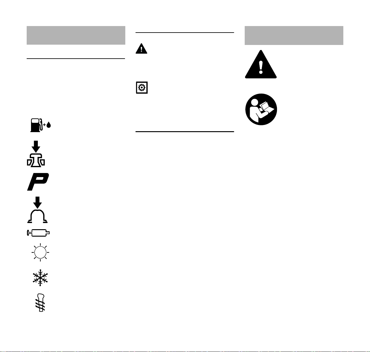
Fuel tank; fuel mixture of
gasoline and engine oil
Operate decompression
valve
Manual fuel pump
Operate manual fuel
pump
Tube of grease
Intake air: Summer
operation
Intake air: Winter
operation
Handle heating
Symbols in text
WARNING
Warning where there is a risk of an
accident or personal injury or serious
damage to property.
NOTICE
Caution where there is a risk of
damaging the machine or its individual
components.
Engineering improvements
STIHL's philosophy is to continually
improve all of its products. For this
reason we may modify the design,
engineering and appearance of our
products periodically.
Therefore, some changes, modifications
and improvements may not be covered
in this manual.
Safety Precautions and
Working Techniques
Because the machine is a
high-speed fast-cutting
power tool, special safety
precautions must be
observed to reduce the
risk of personal injury.
It is important that you
read and understand the
User Manual before commissioning and keep it in
a safe place for future reference. Non-compliance
with the User Manual
may cause serious or
even fatal injury.
Observe all applicable local safety
regulations, e.g. by trade organizations,
social insurance institutions, labor safety
authorities etc.
If you have never used a power tool
before: Have your dealer or other
experienced user show you how to
operate your machine – or attend a
special course to learn how to operate it.
Minors should never be allowed to use
the machine – except for apprentices
over the age of 16 when working under
supervision.
Children, animals and onlookers must
remain at a safe distance.
When not using the machine, it must be
laid down in such a way that it does not
endanger anyone. Ensure that the
machine cannot be used without
authorization.
2
FS 56, FS 56 R, FS 56 C, FS 56 RC

English
The user is responsible for accidents or
risks involving third parties or their
property.
Do not lend or rent your power tool
without the User Manual. Be sure that
anyone using it understands the
information contained in this manual.
The use of machines that emit noise
may be limited to certain hours of the
day as specified by national and/or
regional or local regulations.
Anyone operating the machine must be
well rested, in good physical health and
in good mental condition.
If you have any condition that might be
aggravated by strenuous work, check
with your doctor before operating a
machine.
If you have a pacemaker: The ignition
system of your machine produces an
electromagnetic field of very low
intensity. This field may interfere with
some pacemakers. STIHL recommends
that persons with pacemakers consult
their physician and the pacemaker
manufacturer to reduce any health risk.
Anyone who has consumed alcohol or
drugs or medicines affecting their ability
to react must not operate a power tool.
Depending on the cutting attachment
fitted, use your power tool only for
cutting grass, wild growth, shrubs,
scrub, bushes, small diameter trees and
similar materials.
The machine must not be used for any
other purposes – risk of accidents!
Only use cutting attachments and
accessories that are explicitly approved
for this power tool model by STIHL or
are technically identical. If you have any
questions in this respect, consult your
dealer. Use only high-quality parts and
accessories. in order to avoid the risk of
accidents and damage to the machine.
STIHL recommends the use of genuine
STIHL tools and accessories. They are
specifically designed to match the
product and meet your performance
requirements.
Never attempt to modify your power tool
in any way since this may increase the
risk of personal injury. STIHL excludes
all liability for personal injury and
damage to property caused while using
unauthorised attachments.
The guard provided with your machine
may not protect the operator from all
foreign objects (gravel, glass, wire etc.)
ejected by the revolving cutting
attachment. Ejected objects may also
ricochet and strike the operator.
Do not use a high-pressure washer to
clean the power tool. The solid jet of
water may damage parts of the unit.
Clothing and equipment
Wear proper protective clothing and
equipment.
Clothing must be robust
but allow complete freedom of movement. Wear
close-fitting clothes such
as a boiler suit, not a
loose jacket.
Do not wear clothing which could
become trapped in wood, brush or
moving parts of the machine. Do not
wear a scarf, necktie or jewelry. Tie up
and confine long hair above your
shoulders.
Wear safety boots with
steel toe caps and nonslip soles.
Sturdy shoes with non-slip shoes are
permissible only when using mowing
heads.
WARNING
To reduce the risk of eye
injuries, wear close-fitting safety glasses in
accordance with European Standard EN 166.
Make sure the safety
glasses are a snug fit.
Wear face protection and make sure it is
a good fit. Face protection alone is not
sufficient to protect the eyes.
Wear "personal" sound protection, e.g.
ear defenders.
Wear a safety hard hat for thinning
operations, when working in high scrub
and where there is a danger of head
injuries from falling objects.
Wear sturdy protective
gloves made of a resistant material (e.g.
leather).
STIHL can supply a comprehensive
range of personal protective equipment.
FS 56, FS 56 R, FS 56 C, FS 56 RC
3
English
002BA601 KN
002BA272 KN
Transporting the machine
Always stop the engine.
Carry the machine hanging on the
harness or by the shaft in such a way
that it is balanced.
To reduce the risk of cut injuries, fit
transport guard on the cutting
attachment, even when carrying the tool
for short distances – see also "Mounting
the Transport Guard".
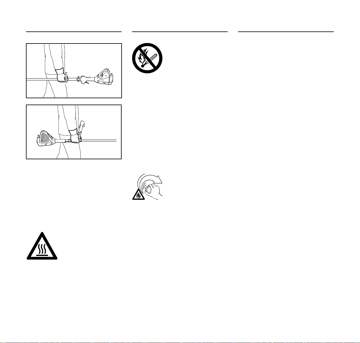
Avoid touching hot parts
of the machine and gearbox – risk of burns!
By vehicle: When transporting in a
vehicle, properly secure your machine to
prevent turnover, damage and fuel
spillage.
Refueling
Gasoline is highly flammable – keep away from
fire or flame – do not spill
any fuel – no smoking.
Always shut off the engine before
refueling.
Do not fuel a hot engine – fuel may spill
and cause a fire.
Open the fuel cap carefully to allow any
pressure build-up in the tank to release
slowly and avoid fuel spillage.
Only refuel the machine in a well
ventilated place. If fuel has been spilled,
immediately clean the machine – do not
allow your clothes to be splashed with
fuel. If that happens, change your
clothes at once.
After refueling, close the
fuel cap as tightly as
possible.
This helps reduce the risk of engine
vibrations causing an incorrectly
tightened fuel cap to loosen or come off
and spill fuel.
Check for leaks. Do not start the engine
if there is a fuel leak – serious or fatal
burns could result!
Before starting
Check that your power tool is properly
assembled and in good condition – refer
to appropriate chapters in the User
Manual.
– Check the fuel system for leaks,
especially the visible parts, e. g.,
fuel cap, hose connections, manual
fuel pump (only in machines with a
manual fuel pump). In case of
leakage and damage, do not start
the engine – risk of fire! Have the
machine serviced by a dealer
before using it
– Use only an approved combination
of cutting attachment, deflector,
handle and harness. All parts must
be assembled properly and
securely
– The stop switch / slide control must
be easy to actuate
– Check the choke lever, throttle
trigger and throttle trigger lockout
for smooth action – throttle trigger
must return automatically to idle
position. The choke lever must
spring back from the g and <
positions to the run position F when
the throttle trigger lockout and
throttle trigger are squeezed
– Check that the spark plug boot is
secure – a loose boot may cause
sparking that could ignite
combustible fumes and cause a fire!
– Cutting attachment or
interchangeable attachment:
correctly fitted, secure and in
perfect condition
4
FS 56, FS 56 R, FS 56 C, FS 56 RC

English
002BA257 KN
002BA080 KN
– Safety devices (e. g., deflector for
cutting attachments, rider plate) for
damage and/or wear. Always
replace damaged parts. Do not use
the machine with a damaged
deflector or worn rider plate (if the
writing and arrows are no longer
discernible)
– Never attempt to modify the controls
or safety devices.
– Keep the handles dry and clean –
free from oil and dirt – this is
important for safe control of the
machine
– Adjust the harness and handle(s) to
suit your height and reach Note the
information in the chapters "Fitting
the Harness" and "Balancing the
Machine".
To reduce the risk of personal injury, do
not operate your power tool if it is
damaged or not properly assembled!
To prepare for emergencies when using
a harness: Practice setting down the
machine quickly. To avoid damage, do
not throw the machine to the ground
when practicing.
Starting the engine
Start the engine at least 3 meters from
the fueling spot, outdoors only.
Place the unit on firm ground in an open
area. Make sure you have good balance
and secure footing. Hold the unit
securely. The cutting attachment must
be clear of the ground and all other
obstructions because it may begin to run
when the engine starts.
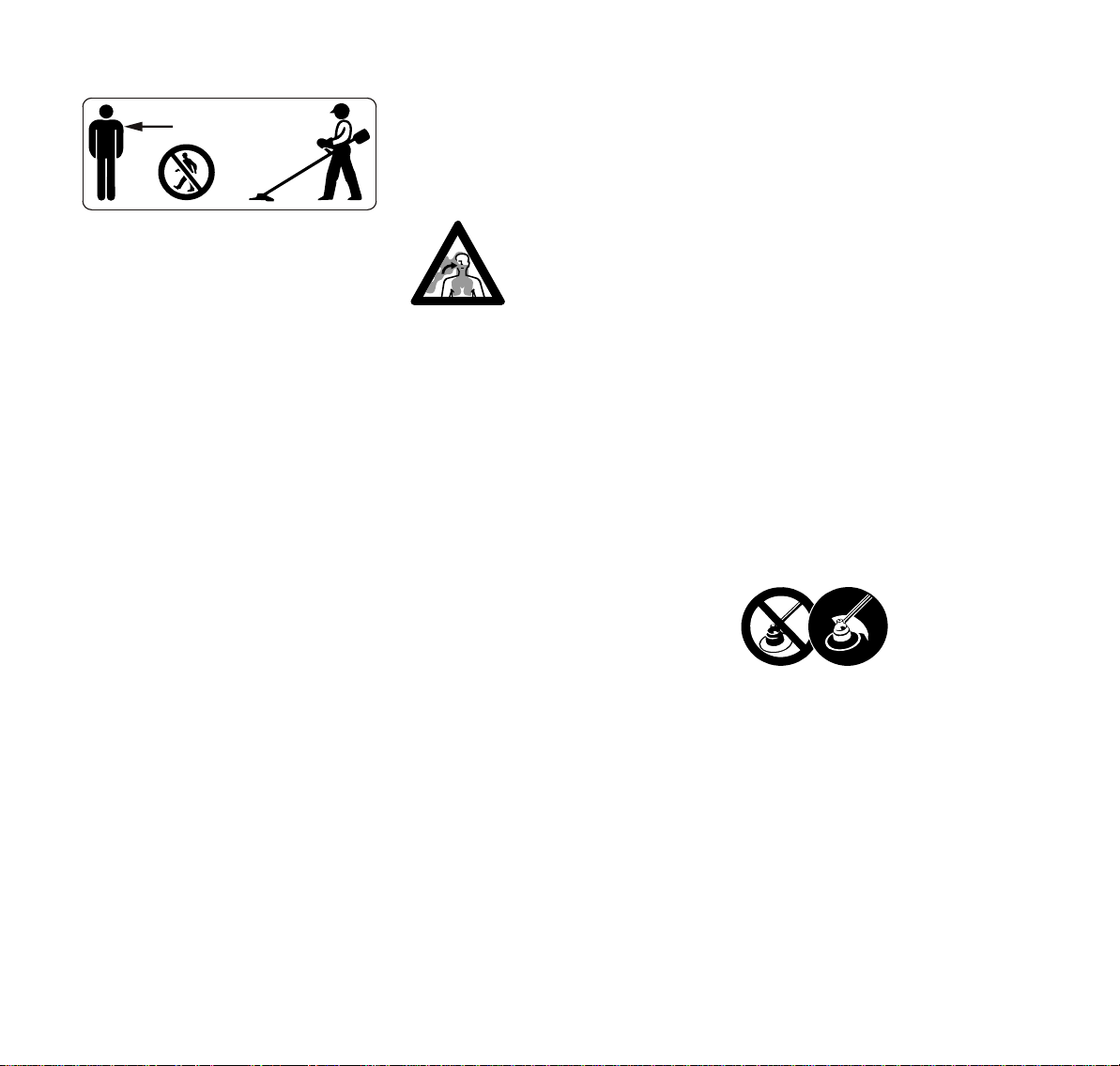
This is a one-person machine – ensure
that there is no-one within 15 meters of
the machine, not even when starting the
power tool! Risk of injury due to ejected
objects!
Avoid contact with the
cutting attachment – risk
of injury!
Do not drop-start the
power tool – start the
engine as described in
the User Manual. The
cutting attachment runs
on for a short while after
releasing the throttle trigger – coasting effect!
Check engine idling: The cutting
attachment must remain at a standstill
when the engine idles – throttle trigger
released.
Keep easily combustible materials
(e. g., wood chips, bark, dry grass, fuel)
away from hot exhaust gases and hot
muffler surfaces – risk of fire!
Holding and guiding the machine
Always hold the unit firmly with both
hands on the handles.
Make sure you always have a firm and
secure footing.
For versions with bike handle
Right hand on control handle, left hand
on grip on handlebar.
For versions with loop handle
Left hand on loop handle, right hand on
control handle, even if you are lefthanded.
While working
Make sure you always have a firm and
secure footing.
In the event of impending danger or in
an emergency, shut off the engine
immediately – move the stop switch /
slide control in the direction of 0.
FS 56, FS 56 R, FS 56 C, FS 56 RC
5
English
15m (50ft)
There is a risk of accident from ejected
objects within a wide area around the
working space, so you must ensure that
there is no-one within a 15 m radius of
the machine. This distance must also be
maintained in relation to objects
(vehicles, window panes) – risk of
property damage! Even at distances
beyond 15 m, the danger cannot be
ruled out.
Check that the engine is properly idling
so that the cutting tool will not continue
rotating after you release the throttle
trigger.
Check and correct the idle speed setting
at regular intervals. If the cutting
attachment still rotates at idle speed,
have your dealer make proper
adjustments or repairs. STIHL
recommends you have this work done
by a STIHL servicing dealer.
Take special care in slippery conditions
– damp, snow, ice, on slopes or uneven
ground.
Watch out for obstacles: tree stumps,
roots – risk of tripping or stumbling!
Only work while standing on the ground,
never on a ladder, work platform or other
unstable surface.
Be particularly alert and cautious when
wearing hearing protection because
your ability to hear warnings (shouts,
alarms, etc.) is restricted.
Take breaks when you start getting tired
or feeling fatigue – risk of accidents!
Work calmly and carefully – in daylight
conditions and only when visibility is
good. Proceed with caution, do not put
others in danger.
As soon as the engine is
running, the power
machine generates toxic
exhaust gas.As soon as
the engine is running, the
power machine generates toxic exhaust gas.
These gases may be
odorless and invisible
and may contain
unburned hydrocarbons
and benzene. Never run
the engine indoors or in
poorly ventilated locations, even if your model
is equipped with a catalytic converter.
To reduce the risk of serious or fatal
injury from breathing toxic fumes,
ensure proper ventilation when working
in trenches, hollows or other confined
locations.
Stop work immediately if you start
suffering from nausea, headaches,
impaired vision (e.g. your field of vision
gets smaller), impaired hearing,
dizziness, or impaired concentration –
these symptoms may possibly be the
result of too-high exhaust gas
concentration – Risk of accidents!
Operate your power tool so that it
produces a minimum of noise and
emissions – do not run the engine
unnecessarily, accelerate the engine
only when working.
To reduce the risk of fire, do not smoke
while operating or standing near your
power tool. Combustible fuel vapor may
escape from the fuel system.
Dust, fumes and smoke produced while
working may be hazardous to health.
Wear respiratory protection in case of
heavy dust or smoke emission.
If your power tool is subjected to
unusually high loads for which it was not
designed (e.g. heavy impact or a fall),
always check that it is in good condition
before continuing work – see also
"Before Starting".
Check in particular that the fuel system
has no leaks and the safety equipment is
fully operative. Never use a power tool
that is no longer safe to operate. In case
of doubt, contact a dealer.
Do not operate your power tool with the
choke lever in the warm start position <
– the engine speed cannot be controlled
in this position.
Never operate the
unit without the
correct deflector for
the type of cutting
attachment being
used – risk of injury
from ejected
objects!
6
FS 56, FS 56 R, FS 56 C, FS 56 RC

English
Check the work site –
rocks, metal objects etc.
could get caught up and
ejected – potentially
beyond a distance of
15 m – risk of injury! Such
objects can also damage
the cutting attachment
and other property (e.g.
parked vehicles,
windows).
Be particularly careful when working on
difficult, densely grown terrain.
When mowing in high shrubbery, under
shrubbery and hedges: Hold the cutting
tool at a working height of at least 15 cm
– avoid risks to animals.
Always shut off the engine before
leaving the unit unattended.
Examine the cutting attachment
periodically at short intervals and as
soon as you note any noticeable
changes:
– Stop the engine, hold the machine
securely, allow the cutting
attachment to come to a stop
– Check condition and secure fitting;
watch out for cracks
– Ensure that the cutting blades are
sharp
– Replace damaged or blunt cutting
attachments immediately, even in
the event of minor hairline cracks
Clean grass and plant residue off the
cutting attachment mounting at regular
intervals – remove any accumulated
material from the cutting attachment and
deflector.
To reduce the risk of injury, shut off the
engine before replacing the cutting
attachment.
The gearbox gets hot
during operation. Never
touch the gearbox – risk
of burns!
If a rotating cutting attachment touches a
rock or another hard object, sparks may
be generated which may possibly ignite
combustible materials. Also dried-out
plants and brushwood are combustible,
above all in hot and dry weather. If there
is a risk of fire, do not use cutting
attachments in the vicinity of
combustible materials, dried-out plants
or brushwood. It is mandatory that you
ask the responsible forestry office about
current fire hazards.
Using mowing heads
Extend the cutting attachment deflector
with the attached parts specified in the
User Manual.
Only use a deflector with a properly fitted
blade, which limits the mowing line to the
permissible length.
For manually adjustable mowing heads,
always switch off the engine before
adjusting the mowing line – risk of injury!
Misuse with mowing lines that are too
long reduces the working speed of the
engine. The constant slipping of the
clutch causes overheating and damage
to important components (e. g. clutch,
plastic housing parts) – e. g. due to the
cutting attachment rotating during idling
– risk of injury!
When using metal cutting attachments
STIHL recommends the use of original
STIHL metal cutting attachments. These
have been optimized for the machine
and the user’s requirements.
Metal cutting attachments rotate very
fast, generating forces acting on the
attachments and on the cuttings.
Metal cutting attachments must be
sharpened in regular intervals in
accordance with the instructions.
Unevenly sharpened metal cutting
attachments generate an imbalance
which may cause extreme loads on the
machine – risk of breakage!
Dull or improperly sharpened cutting
edges can put a higher load on the
cutting attachment and increase the risk
of injuryfrom cracked or broken parts.
After each contact of the metal cutting
attachment with hard objects (e.g.
stones, rocks, metal parts), check it for
damage (e.g. tears and deformation).
Burrs and other visible accumulated
material must be removed since they
may come loose at any time while the
machine is running and then be ejected
– risk of injury!
Do not continue using or attempt to
repair damaged or cracked cutting
attachments by means of welding,
straightening or modifying the shape
(unbalanced).
Particles or pieces may come off and hit
the operator or a bystander at a high
speed – risk of most severe injuries!
To reduce the above-named risks
involved in operating a metal cutting
attachment, ensure that the diameter of
FS 56, FS 56 R, FS 56 C, FS 56 RC
7

English
your metal cutting attachment is not too
big. Also, the attachment must not be
too heavy. It must be made of highquality materials and have a suitable
geometry (shape, thickness).
A metal cutting attachment not made by
STIHL must not have a different weight,
thickness, shape or a larger diameter
than the largest STIHL metal cutting
attachment approved for this metal
cutting attachment – risk of injury!
Vibrations
Prolonged use of the power tool may
result in vibration-induced circulation
problems in the hands (whitefinger
disease).
No general recommendation can be
given for the length of usage because it
depends on several factors.
The period of usage is prolonged by:
– Hand protection (wearing warm
gloves)
– Work breaks
The period of usage is shortened by:
– Any personal tendency to suffer
from poor circulation (symptoms:
frequently cold fingers, tingling
sensations).
– Low outside temperatures.
– The force with which the handles
are held (a tight grip restricts
circulation).
Continual and regular users should
monitor closely the condition of their
hands and fingers. If any of the above
symptoms appear (e.g. tingling
sensation in fingers), seek medical
advice.
Maintenance and Repairs
Service the machine regularly. Do not
attempt any maintenance or repair work
not described in the instruction manual.
Have all other work performed by a
servicing dealer.
STIHL recommends that you have
servicing and repair work carried out
exclusively by an authorized STIHL
servicing dealer. STIHL dealers are
regularly given the opportunity to attend
training courses and are supplied with
the necessary technical information.
Only use high-quality replacement parts
in order to avoid the risk of accidents
and damage to the machine. If you have
any questions in this respect, consult a
servicing dealer.
STIHL recommends the use of genuine
STIHL replacement parts. These parts
are specifically designed to match your
machine model and meet your
performance requirements.
To reduce the risk of injury from
unintentional engine startup, always
shut off the engine and disconnect the
spark plug boot before performing any
repairs, maintenance or cleaning work. –
Exception: Carburetor and idle speed
adjustments.
Do not turn the engine over on the
starter with the spark plug boot or spark
plug removed since there is otherwise a
risk of fire from uncontained sparking.
To reduce the risk of fire, do not service
or store your machine near open flames.
Check the fuel filler cap for leaks at
regular intervals.
Use only a spark plug of the type
approved by STIHL and make sure it is
in good condition – see "Specifications".
Inspect the ignition lead (insulation in
good condition, secure connection).
Check the condition of the muffler.
To reduce the risk of fire and damage to
hearing, do not operate your machine if
the muffler is damaged or missing.
Do not touch a hot muffler since burn
injury will result.
Maintenance, replacement, or repair of
the emission control devices and
systems may be performed by any
nonroad engine repair establishment or
individual. However, if you make a
warranty claim for a component which
has not been serviced or maintained
properly, STIHL may deny coverage.
For any maintenance please refer to the
maintenance chart and to the warranty
statement near the end of the instruction
manual.
Symbols on Deflectors
An arrow on the deflector shows the
correct direction of rotation of the cutting
attachments.
Some of the following symbols are
applied to the outside of the deflector to
indicate the approved combination of
cutting tool and deflector.
8
FS 56, FS 56 R, FS 56 C, FS 56 RC
English
000BA015 KN
002BA049 KN
Shoulder strap
Use deflector in
combination with
mowing heads
only. Do not use
metal cutting
attachments.
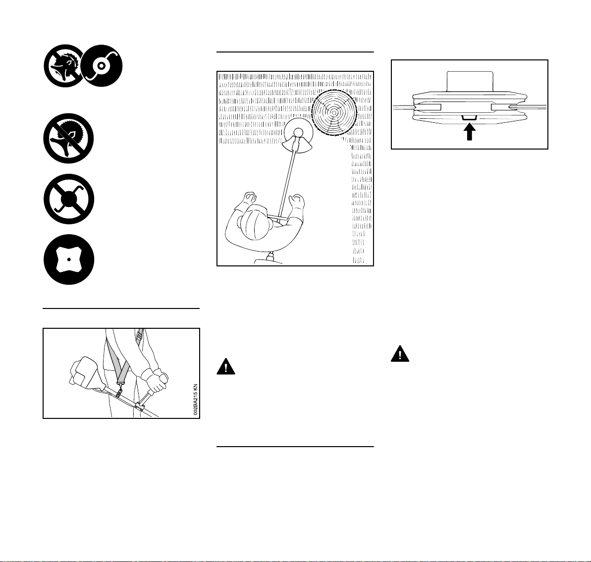
Do not use deflector with
brush knives or circular
saw blades.
Do not use deflector with
mowing heads.
Use deflector in combination with grass cutting
blades only.
Mowing Head with Nylon Line
Nylon line achieves a soft cut for edging
and trimming around trees, fence posts,
etc. – less risk of damaging tree bark.
The mowing head comes with an
instruction leaflet. Refill the mowing
head with nylon line as described in the
instruction leaflet.
WARNING
To reduce the risk of serious injury,
never use wire or metal-reinforced line in
place of the nylon line.
Check the wear limit marks!
If one of the wear limit marks on the
PolyCut mowing head is worn through
(arrow): Do not continue using the
mowing head. Install a new one. There
is otherwise a risk of injury from thrown
parts of the head.
It is important to follow the maintenance
instructions for the PolyCut mowing
head.
The PolyCut can also be equipped with
mowing line in place of the polymer
blades.
The mowing head comes with
instruction leaflets. Equip the mowing
head with polymers blades or nylon line
as described in the instruction leaflets.
WARNING
Never use wire in place of the nylon
mowing line – risk of injury.
N Use a shoulder strap.
N With the engine running, attach the
machine to the shoulder strap.
Grass cutting blades must always be
used in combination with a shoulder
strap.
FS 56, FS 56 R, FS 56 C, FS 56 RC
STIHL Polycut Mowing Head with
Polymer Blades
For mowing unobstructed edges of
meadows (without posts, fences, trees
or similar obstacles).
9
English
002BA135 KN
000BA020 KN
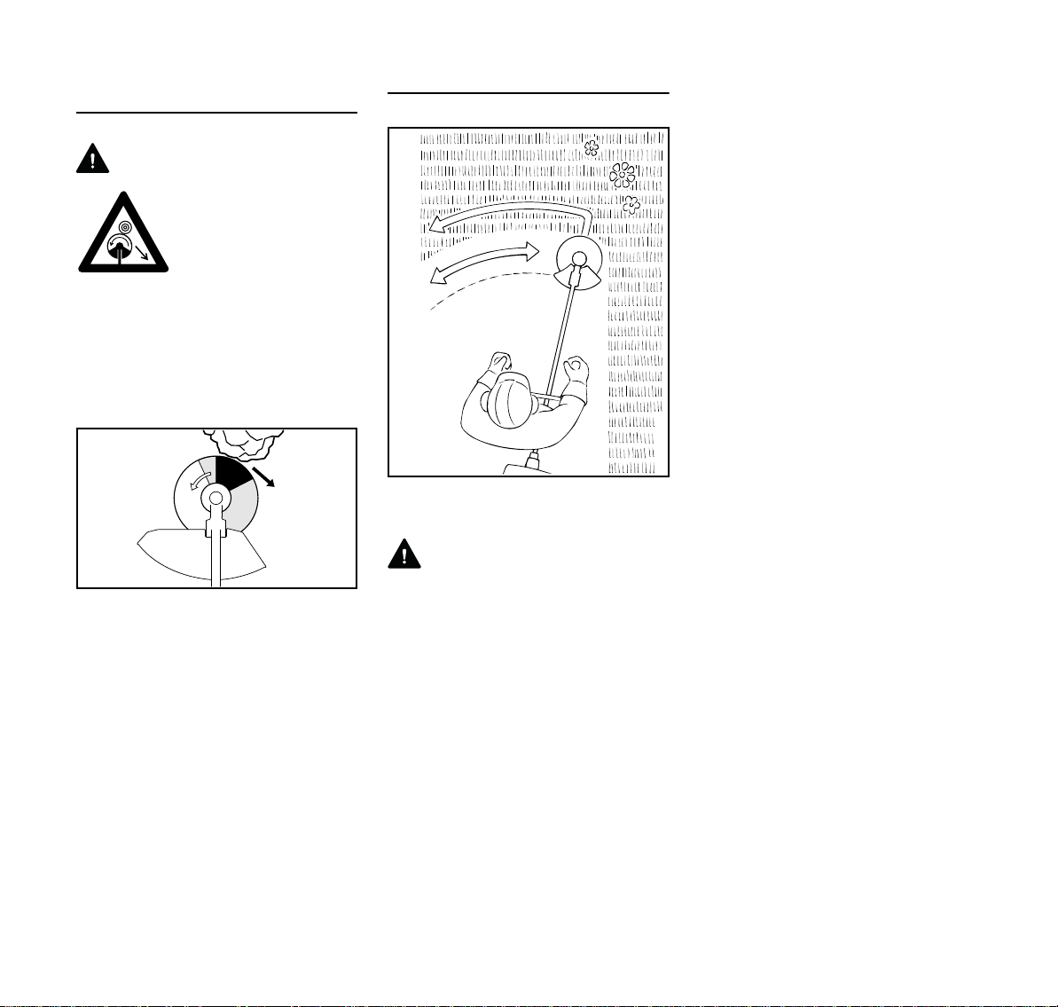
Risk of Kickout (Blade Thrust) with Metal
Cutting Attachments
WARNING
When using metal cutting attachments there is
a risk of kickout when the
rotating blade comes into
contact with a solid object
such as a tree trunk,
branch, tree stump, rock
or similar. The machine is
thrown to the right or to
the rear – opposite to the
attachment's direction of
rotation.
The risk of kickout is greatest when the
black area of the rotating cutting
attachment comes into contact with a
solid object.
Grass Cutting Blade
Use for grass and weeds only – sweep
the brushcutter in an arc like a scythe.
WARNING
Improper use may damage the grass
cutting blade – risk of injury from thrown
parts.
Resharpen the grass cutting blade
according to instructions when it has
dulled noticeably.
10
FS 56, FS 56 R, FS 56 C, FS 56 RC
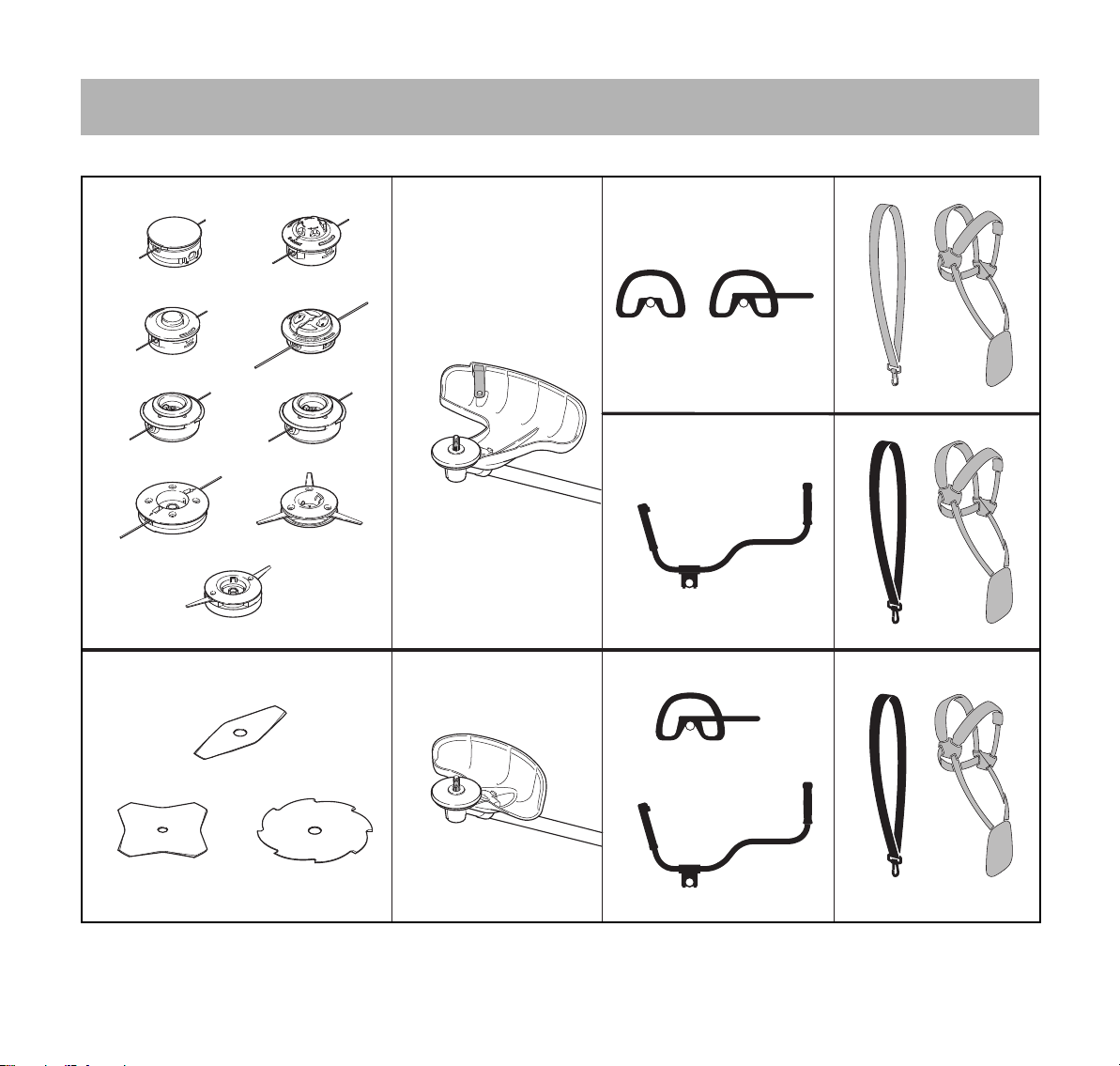
Approved Combinations of Cutting Attachment, Deflector, Handle and Harness
Cutting attachment Deflector Handle Carrying strap
English
1
2
15
16
17
3
4
19
21
13
5
7
6
8
18
20
21
9
16
17
10
14
11
FS 56, FS 56 R, FS 56 C, FS 56 RC
12
18
20
21
0000078652_003
11
English
Permissible combinations
Choose the correct combination from
the table depending on the cutting tool!
WARNING
For safety reasons only the cutting
attachments, deflector, handle and
harness versions within one line of the
table may be combined with one
another. No other combinations are
permitted because of the risk of
accidents.
Cutting attachments
Mowing heads
1 STIHL SuperCut 20-2
2 STIHL AutoCut C 25-2
3 STIHL AutoCut 25-2 / AutoCut 27-2
4 STIHL AutoCut C 26-2
5 STIHL TrimCut 31-2
6 STIHL TrimCut 32-2
7 STIHL DuroCut 20-2
8 STIHL PolyCut 20-3
9 STIHL PolyCut 28-2
Metal cutting tools
10 Grass cutting blade 230-2
(230 mm dia.)
11 Grass cutting blade 230-4
(230 mm dia.)
12 Grass cutting blade 230-8
(230 mm dia.)
WARNING
Grass cutting blades of materials other
than metal must not be used.
Deflectors
13 Guard with blade for mowing heads
14 Deflector for metal cutting
attachments
Handles
15 Loop handle
16 Loop handle with
17 Barrier bar
18 Bike handle
Shoulder straps
19 Shoulder strap can be used
20 Shoulder strap must be used
21 Full harness can be used
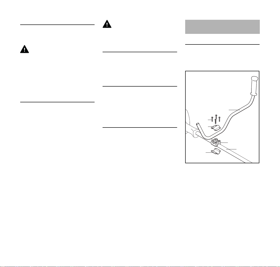
Mounting the Bike Handle
Mounting the Handlebar
Mount the handlebar on the drive tube
about 10 cm (4 in) forward of the engine
housing.
3
5
4
1
2
6
002BA274 KN
N Place the handle support (1) on the
drive tube (2).
N Place the handlebar (3) in the
handle support.
N Fit the clamp (4) on the handle
support. Insert the screws (5)
through the holes in the parts and
screw them into clamp (6) as far as
stop – tighten them only moderately
at this stage.
12
FS 56, FS 56 R, FS 56 C, FS 56 RC
English
3
6
547BA027 KN
1
2
4
6
5
A
1
B
002BA275 KN
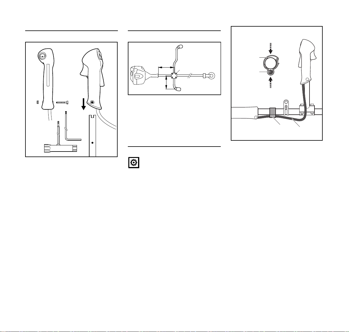
Mounting the Control Handle
N Take out the screw (1) – the nut (2)
remains in the control handle (3).
N Push the control handle onto the
handlebar (5) until the holes (6) line
up – the throttle trigger (4) must
point towards the gearbox.
N Insert the screw (1) and tighten it
down firmly.
Adjusting and securing the handlebar
N Align the handlebar so that
distance A is about 20 cm (8 in) and
distance B about 15 cm (6 in).
N Tighten down the screws (1) firmly
in a crosswise pattern.
Fitting the Throttle Cable
NOTICE
Do not kink the throttle cable or lay it in
tight radii – make sure the throttle trigger
moves freely.
2
1
2
N Position the throttle cable
retainer (2) and throttle cable (1)
against the drive tube.
N Close the throttle cable retainer (2).
The retainer (2) snaps into place.
1
002BA276
FS 56, FS 56 R, FS 56 C, FS 56 RC
13

English
002BA586 KN
002BA587 KN
4
002BA588 KN
3
5
3
5
1
2
1
2
3
3
002BA609 KN
8
6
4
002BA610 KN
7
9
1
1
Mounting the Loop Handle
A factory-new machine comes with the
loop handle already mounted.
Using the Barrier Bar
A barrier bar may have to be mounted to
suit the cutting attachment you intend to
use – see "Approved Combinations of
Cutting Attachment, Deflector, Handle
and Harness".
The barrier bar comes standard with the
machine or is available as a special
accessory.
Mounting the Barrier Bar
N Take out the screws (1) and remove
along with washers (2) and nuts (3).
N Remove the loop handle (4) and
clamps (5).
N Fit the square nuts (3) in the barrier
bar (6); the holes must line up.
N Place the clamp (7) in the loop
handle (4) and position them both
against the drive tube (8).
N Position the clamp (8) against the
drive tube.
N Place the barrier bar (6) in position
as shown.
N Line up the holes.
N Insert the screws (1) in the holes
and screw them into the barrier bar
as far as stop.
N Go to "Adjusting and Securing the
Loop Handle".
Leave the barrier bar permanently
mounted to the loop handle.
14
FS 56, FS 56 R, FS 56 C, FS 56 RC

English
4
002BA611 KN
A
1
002BA529 KN
002BA142 KN
1
2
1
Adjusting and Securing the Loop Handle
The loop handle can be adjusted to suit
the height and reach of the operator and
the application by changing
distance (A).
Recommendation: distance (A):
about 15 cm (5.9 in)
N Slide the handle to the required
position.
N Line up the loop handle (4).
N Tighten down the screws until the
loop handle can no longer be
rotated on the drive tube. If no
barrier bar is fitted – lock the nuts if
necessary.
Fitting the Carrying Ring
Polymer Version
For position of carrying ring see "Main
Parts".
N Push the carrying ring (1) over the
drive tube.
N Insert the M5 nut in the hex recess
in the carrying ring.
N Fit the M5x14 screw.
N Line up the carrying ring.
N Tighten down the screw firmly.
Metal Version
For position of carrying ring see "Main
Parts".
N Place the clamp (1) against the
drive tube with the tapped hole on
the left (viewed from engine).
N Squeeze the two ends of the clamp
together and hold in that position.
N Insert the M6x14 screw (2).
N Line up the carrying ring.
N Tighten down the screw firmly.
FS 56, FS 56 R, FS 56 C, FS 56 RC
The carrying ring comes standard with
the machine or is available as a special
accessory.
15
English
002BA262 KN
1
002BA263 KN
2
0414BA007 KN
002BA104 KN
002BA265 KN
1
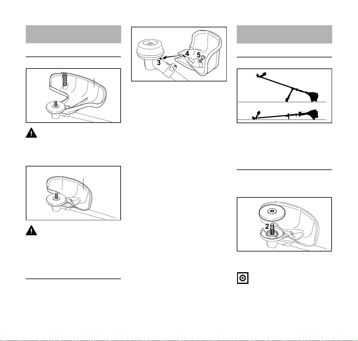
Mounting the Deflector
Use the right deflector
WARNING
Deflector (1) is approved for mowing
heads only and must therefore be
mounted before fitting a mowing head
Mounting the Cutting
Attachment
Placing power tool on the ground
N Position the deflector against the
gearbox so that the lug (3) engages
the recess (4) in the deflector.
N Insert the screw (5) and tighten it
down firmly.
N Shut off the engine.
N Lay your power tool on its back so
that the cutting attachment
mounting face is pointing up.
Fitting the Thrust Plate
The machine comes standard with the
thrust plate.
WARNING
Deflector (2) is approved for grass
cutting blades only and must therefore
be mounted before fitting a grass cutting
blade.
Mounting the Deflector
Deflectors (1) and (2) are both mounted
to the gearbox in the same way.
16
N Slip the thrust plate (1) over the
shaft (2).
NOTICE
The thrust plate on the gearbox is
necessary for mounting cutting tools.
FS 56, FS 56 R, FS 56 C, FS 56 RC

English
2
002BA266 KN
002BA267 KN
3
4
5
7
8
2
002BA166 KN
7
Mounting Hardware for Cutting
Attachments
The mounting hardware supplied
depends on the cutting attachment that
comes as original equipment with the
new machine.
If mounting hardware is not packed with
machine
Only mowing heads may be used which
mount directly to the shaft (2).
If mounting hardware is packed with
machine
Mowing heads and metal cutting tools
may be mounted.
The nut (3), rider plate (4) and thrust
washer (5) are required to secure some
mowing heads.
These parts are included in a kit
supplied with the machine and are also
available as special accessories.
Block the shaft.
N Insert the stop pin (7) or offset
screwdriver (7) in the hole (8) in the
gearbox as far as stop – and apply
slight pressure.
N Rotate shaft or cutting attachment
until the stop pin slips into position
and blocks the shaft.
Mounting the Cutting Attachment
WARNING
Use a deflector that matches the cutting
attachment – see "Mounting the
Deflector".
Fitting the mowing head with screw
mounting
Keep the supplement sheet for the
mowing head in a safe place.
FS 56, FS 56 R, FS 56 C, FS 56 RC
The output shaft (2) must be blocked
with the stop pin (7) or screwdriver (7) to
mount or remove cutting tools. These
parts come standard with the machine or
are available as special accessories.
17

English
1
002BA385 KN
1
3
2
681BA050 KN
681BA051 KN
6
9
7
8
5
4
WARNING
Wear protective gloves to reduce the
risk of direct contact with the sharp
cutting edges.
Mount only metal cutting attachments.
Check direction of rotation of cutting
attachment
N Fit the thrust plate
N Turn the mowing head
anticlockwise on the shaft (1) as far
as it will go
N Retain the shaft
N Tighten the mowing head
NOTICE
Remove the tool that was used to block
the shaft.
Removing the Mowing Head
N Retain the shaft
N Turn the mowing head clockwise
Mounting Metal Cutting Attachment
Keep the leaflet and packaging of the
metal cutting tool in a safe place.
18
The cutting edges of the grass cutting
blades (1) and (2) may point in either
direction – these cutting attachments
must be turned over regularly to reduce
one-sided wear.
Cutting edges of grass cutting blade (3)
must point clockwise.
WARNING
Direction of rotation is indicated by an
arrow on the inside of the deflector.
N Place the cutting attachment (4) on
the thrust plate (5).
WARNING
Collar (see arrow) must engage the
cutting attachment's mounting hole.
Securing the cutting attachment
N Fit the thrust washer (6) – convex
side must face up.
N Fit the rider plate (7).
N Block the shaft (8).
N Screw the mounting nut (9) on to the
shaft counterclockwise and tighten
it down firmly.
WARNING
If the mounting nut has become too
loose, fit a new one.
FS 56, FS 56 R, FS 56 C, FS 56 RC

English
NOTICE
Remove the tool used to block the shaft.
Removing the Metal Cutting Attachment
WARNING
Wear protective gloves to reduce the
risk of direct contact with the sharp
cutting edges.
N Block the shaft.
N Unscrew the mounting nut
clockwise.
N Remove cutting attachment and its
mounting hardware from the
gearbox – but do not remove the
thrust plate (5).
Fuel
This engine is certified to operate on
unleaded gasoline and with the mix ratio
50:1.
Your engine requires a mixture of highquality premium gasoline and highquality two-stroke air-cooled engine oil.
Use premium branded unleaded
gasoline with a minimum octane rating
of 89 (R+M)/2.
Note: Models equipped with a catalytic
converter require unleaded gasoline. A
few tankfuls of leaded gasoline can
reduce the efficiency of the catalytic
converter by more than 50%.
Fuel with a lower octane rating may
result in preignition (causing "pinging")
which is accompanied by an increase in
engine temperature. This, in turn,
increases the risk of the piston seizure
and damage to the engine.
The chemical composition of the fuel is
also important. Some fuel additives not
only detrimentally affect elastomers
(carburetor diaphragms, oil seals, fuel
lines etc.), but magnesium castings as
well. This could cause running problems
or even damage the engine. For this
reason it is essential that you use only
high-quality fuels!
Fuels with different percentages of
ethanol are being offered. Ethanol can
affect the running behaviour of the
engine and increase the risk of lean
seizure.
Gasoline with an ethanol content of
more than 10% can cause running
problems and major damage in engines
with a manually adjustable carburetor
and should not be used in such engines.
Engines equipped with M-Tronic can be
run on gasoline with an ethanol content
of up to 25% (E25).
Use only STIHL two-stroke engine oil or
equivalent high-quality two-stroke aircooled engine oils for mixing.
We recommend STIHL 50:1 two-stroke
engine oil since it is specially formulated
for use in STIHL engines.
To ensure the maximum performance of
your STIHL engine, use a high quality 2cycle engine oil. To help your engine run
cleaner and reduce harmful carbon
deposits, STIHL recommends using
STIHL HP Ultra 2-cycle engine oil or ask
your dealer for an equivalent fully
synthetic 2-cycle engine oil.
To meet the requirements of EPA and
CARB we recommend to use STIHL HP
Ultra oil.
Do not use BIA or TCW (two-stroke
water cooled) mix oils!
Use only STIHL 50:1 heavy-duty engine
oil or an equivalent quality two-stroke
engine oil for the fuel mix in models
equipped with a catalytic converter.
Take care when handling gasoline.
Avoid direct contact with the skin and
avoid inhaling fuel vapour.
The canister should be kept tightly
closed in order to avoid any moisture
getting into the mixture.
FS 56, FS 56 R, FS 56 C, FS 56 RC
19

English
547BA045 KN
002BA447 KN
002BA448 KN
The fuel tank and the canister in which
fuel mix is stored should be cleaned
from time to time.
Fuel mix ratio
Only mix sufficient fuel for a few days
work, not to exceed 30 days of storage.
Store in approved safety fuel-canisters
only. When mixing, pour oil into the
canister first, and then add gasoline.
Examples
Gasoline Oil (STIHL 50:1 or equiva-
lent high-quality oils)
liters liters (ml)
10.02(20)
5 0.10 (100)
10 0.20 (200)
15 0.30 (300)
20 0.40 (400)
25 0.50 (500)
Dispose of empty mixing-oil canisters
only at authorized disposal locations.
Fueling
Preparations
N Before fueling, clean the filler cap
and the area around it to ensure that
no dirt falls into the tank.
N Position the machine so that the
filler cap is facing up.
Opening the Tank Cap
Filling Up with Fuel
Take care not to spill fuel while fueling
and do not overfill the tank.
STIHL recommends you use the STIHL
filler nozzle for fuel (special accessory).
N Fill up with fuel.
Closing the Tank Cap
N Place the cap in the opening.
N Turn the cap clockwise as far as
stop and tighten it down as firmly as
possible by hand.
20
N Turn the cap counterclockwise until
it can be removed from the tank
opening.
N Remove the tank cap.
FS 56, FS 56 R, FS 56 C, FS 56 RC

English
3
002BA228 KN
2
1
1
2
1
2
002BA311 KN
Fitting the Harness
The type and style of the harness
depend on the market.
The use of the harness is described in
the chapter on "Approved Combinations
of Cutting Attachment, Deflector, Handle
and Harness".
Shoulder strap
Full Harness
N Put on the harness (1) and close the
locking plate (3).
N Adjust the length of the strap – with
the machine attached, the
carabiner (2) must be about a
hand's width below your right hip.
N Balance the machine – see
"Balancing the Machine".
Balancing the Machine
The type and style of the harness and
carabiner (spring hook) depend on the
market.
The carrying ring is integrated in the
control handle on loop-handled units–
see "Main Parts". Loop-handled units do
not need to be balanced.
Attaching the unit to the harness
N Attach the carabiner (1) to the
carrying ring (2) on the drive tube.
N Put on the shoulder strap (1).
N Adjust the length of the strap so that
the carabiner (2) is about a hand’s
width below your right hip.
N Balance the machine.
FS 56, FS 56 R, FS 56 C, FS 56 RC
21

English
002BA313 KN
1
2
1
2
002BA312 KN
1
002BA268 KN
2
3
N Loosen the screw (3).
Floating position
When the correct floating position has
been reached:
N Tighten down the screw on the
carrying ring firmly.
Detaching the unit from the harness
N Press down the bar on the
carabiner (1) and pull the carrying
ring (2) out of the carabiner.
Starting / Stopping the
Engine
Controls
Version with Bike Handle
N Mowing heads and grass cutting
blades should just touch the ground.
Proceed as follows to adjust the floating
position:
N Move the carrying ring up or down
the drive tube – tighten the screw
moderately – let the unit go and wait
until is its balanced – then check the
floating position.
22
1 Throttle trigger lockout
2 Throttle trigger
3 Stop switch with Run and 0 =Stop
positions.
FS 56, FS 56 R, FS 56 C, FS 56 RC

English
002BA269 KN
1
3
2
4
457BA046 KN
5
547BA016 KN
5
547BA017 KN
547BA018 KN
Version with Loop Handle
1 Throttle trigger lockout
2 Throttle trigger
3 Stop switch with Run and 0 = Stop
positions.
Function of stop switch and ignition
system
The stop switch is normally in the Run
position, i.e. when it is not depressed:
The ignition is switched on – the engine
is ready to start. If the stop switch is
moved to the 0 position, the ignition is
switched off. The ignition is switched on
again automatically after the engine
stops.
Starting the Engine
N Press the manual fuel pump
bulb (4) at least five times – even if
the bulb is filled with fuel.
Cold engine (cold start)
N Press in the choke lever (5) and turn
it to g at the same time.
Warm engine (warm start)
Also use this setting if the engine has
been running but is still cold.
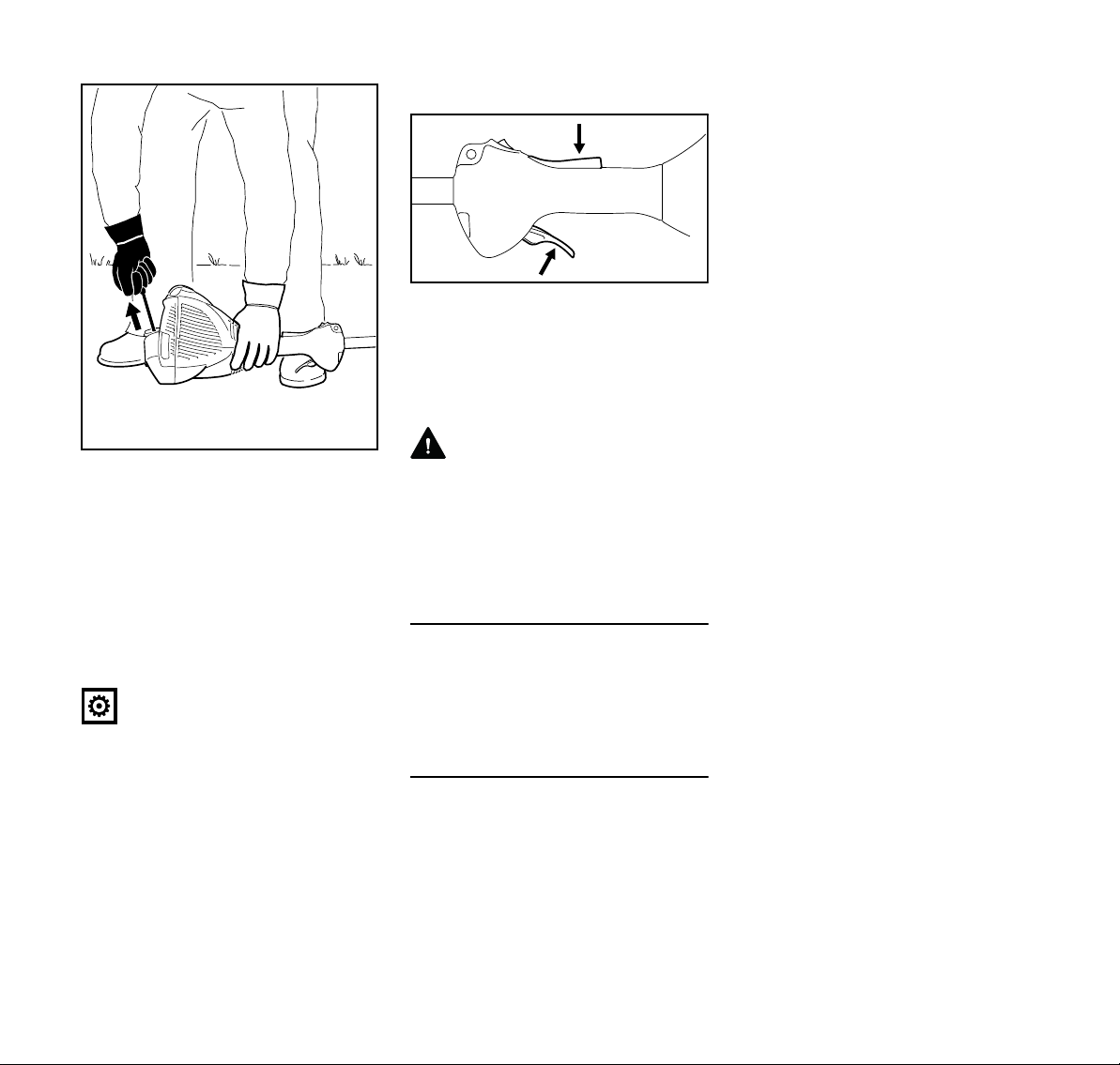
Cranking
N Place the unit on the ground: It must
rest securely on the engine support
and the deflector.
N If fitted: Remove the transport guard
from the cutting attachment.
To reduce the risk of accidents, check
that the cutting attachment is not
touching the ground of any other
obstacles.
N Make sure you have a firm footing,
either standing, stooping or
kneeling.
N Hold the unit firmly on the ground
with your left hand and press down
– do not touch the throttle trigger,
lockout lever or stop switch.
NOTICE
Do not stand or kneel on the drive tube.
FS 56, FS 56 R, FS 56 C, FS 56 RC
N Press in the choke lever (5) and turn
it to < at the same time.
23
English
547BA020 KN
547BA021 KN
N Hold the starter grip with your right
hand.
Version without ErgoStart
N Pull the starter grip slowly until you
feel it engage and then give it a brisk
strong pull.
Version with ErgoStart
N Pull the starter grip steadily.
NOTICE
Do not pull out the starter rope all the
way – it might otherwise break.
N Do not let the starter grip snap back.
Guide it slowly back into the housing
so that the starter rope can rewind
properly.
N Continue cranking until the engine
runs.
As soon as the engine runs
N Press down the throttle trigger
lockout and open the throttle – the
choke lever moves to the run
position F. After a cold start, warm
up the engine by opening the
throttle several times.
WARNING
Make sure the carburetor is correctly
adjusted. The cutting attachment must
not rotate when the engine is idling.
Your machine is now ready for
operation.
Stopping the Engine
N Move the stop switch in the direction
of 0 – the engine stops – release
the stop switch – it springs back to
the run position.
Other Hints on Starting
Engine stalls in cold start position g or
under acceleration
N Move the choke knob to < and
continue cranking until the engine
runs.
Engine does not start in warm start
position <
N Move the choke knob to g and
continue cranking until the engine
runs.
If the engine does not start
N Check that all settings are correct.
N Check that there is fuel in the tank
and refuel if necessary.
N Check that the spark plug boot is
properly connected.
N Repeat the starting procedure.
Engine is flooded
N Move the choke knob to F and
continue cranking until the engine
runs.
Fuel tank run until completely dry
N After refueling, press the manual
fuel pump bulb at least five times –
even if the bulb is filled with fuel.
N Set the choke lever to suit the
engine temperature.
N Now start the engine.
24
FS 56, FS 56 R, FS 56 C, FS 56 RC
 Loading...