

Stihl RE 140 K, RE 160 K Repair Manual

RE 140 K, 160 K
CONTENTS
1. Foreword 2
1.1 Note on RE 160 K 2
2. Safety regulations 2
3. Technical
specifications 3
3.1 Motor 3
3.2 Pump 3
3.3 Weights and
dimensions 3
3.4 Capacities 3
3.5 Tightening torques 4
4. Summary of
possible faults 5
4.1 High-pressure pump 5
4.2 Electric motor 7
5. Housing 8
5.1 Removing /
fitting the shroud 8
5.2 Removing /
installing the motor /
pump unit 8
5.3 Chassis 9
6. Safety control block 9
7.4 Removing / installing
pump housing and
pump piston 15
7.5 Disassembly /
assembly of
pump piston 15
7.6 Replacing
high-pressure cups
and oil seals 16
7.7 Replacing thrust
bearings 17
8. Electric motor 18
8.1 Removal 18
8.2 Installation 21
9. Electrical system 23
9.1 Circuit diagram 23
9.2 Removing / installing
electrical components 24
9.2.1 Switch housing 24
9.2.2 Switch 25
9.2.3 Power cable 25
9.2.4 Capacitor 26
9.2.5 Microswitch 27
10. Spray attachment 27
10.1 Spray gun 28
10.2 Spray lance,
spray head 28
6.1 Removing / installing
11. Oil change 30
the safety control block 9
6.2 Removing / installing
the control piston 10
6.3 Setting the pressure
12. Special tools and
service tools 31
control system 11
6.4 Injector 12
6.5 Non-return valve 12
12.1 Special tools 31
12.2 Service tools 31
6.6 Detergent metering
and non-return valve 13
7. High-pressure pump 14
7.1 Screen in intake port
(water inlet) 14
7.2 Removing / installing
delivery valves 14
7.3 Removing / installing
valve block and
intake valves 14
© 2000, Andreas Stihl AG & Co., Waiblingen
RE 140 K, 160 K 1

1. FOREWORD 2. Safety regulations1.1 Note on RE 160 K
This Repair Manual contains a
detailed description of the
fundamental repair work on STIHL
high-pressure cleaners of series
STIHL RE 140 K, 160 K.
A test bed with the necessary
water and power supplies should
be provided for the repair work.
The unit must be connected to the
pressurized water supply and the
fault described by the customer
reproduced, with the customer
demonstrating the fault if
necessary. The customer’s
attention must be drawn to the
User Manual if the machine is
operated incorrectly.
Faults may be due to several
causes. The "Summary of
possible faults" should therefore
be consulted see 4.
The illustrated spare parts lists
must also be used for all repair
work. These lists show the
installation position and order in
which the individual assemblies
should be assembled. Microfilms
are more up-to-date than printed
spare parts lists.
Please refer to the preceding
Repair Manual for the RE 160 K if
the procedures described and
illustrated in this Repair Manual do
not correspond with your machine.
High-pressure cleaners may only
be repaired by qualified
electricians (in accordance with
DIN VDE 0701 and accident
prevention regulations VBG 4 in
Germany) with due regard for
national safety regulations and the
provisions of the User Manual.
Note the "Technical Information"
bulletins! They contain
information on technical changes
implemented after publication
of this Repair Manual. The
Technical Information bulletins
also supplement the spare parts
list until a new edition is printed!
Repair Manuals and Technical
Information bulletins should
always be kept on hand wherever
repairs are carried out.
They must not be passed on to
third parties.
Only original STIHL spare parts
maybeused!
2 RE 140 K, 160 K

3. TECHNICAL SPECIFICATIONS
RE 140 K RE 160 K
3.1 Motor
Voltage: 230 V / 240 V *) 230 V / 240 V *)
Frequency: 50 Hz / 60 Hz *) 50 Hz / 60 Hz *)
Power output: 2.3 - 2.9 kW *) 2.2 - 3.3 kW *)
Fuse: 16A**) 16A**)
Protection class: I I
Type of protection: IP X5 IP X5
3.2 Pump
Max. working pressure: 140 bar 150 bar
Permissible excess pressure: 150 bar 160 bar
Flow rate: 500 l/h 500 - 550 l/h *)
Suctionlift: 0.5m 0.5m
Max. water feed temperature:
- Pressurized water supply: 50 °C 50 °C
- In suction operation: 40 °C 40 °C
3.3 Weights and dimensions
Length approx.: 370 mm 370 mm
Width approx.: 270 mm 270 mm
Height approx.: 860 mm 860 mm
Weight approx.: 20.0 kg 25.0 kg
3.4 Capacities
High-pressure pump: 100 ml 100 ml
Oil grade: SAE 15 W 40 SAE 15 W 40
*) Depends on country concerned
**) Australia / New Zealand: 10 A
**) GB / N. Ireland / Malaysia: 13 A
**)
RE 140 K, 160 K 3

3.5 Tightening torques
Tightening torque
Assembly Connecting element Thread size Nm Remarks
Safety control block Socket-head screw M5x30 7 1)
to valve block
Valve block to Socket-head screw M6x35 15 1)
pump housing
Pump housing to Socket-head screw M6x30 10 1)
drive housing
Drive housing to Socket-head screw M5x25 7 1) 2)
stator housing
Bearing cover and Hex bolt M6x25 7 1) 3)
drive housing to
stator housing
Screw plug, Hexagonal socket-head bolt R1/4" 7 3)
drive housing
Remarks
1) Thread must be clean and dry
2) RE 140 K only
3) RE 160 K only
4 RE 140 K, 160 K

4. SUMMARY OF POSSIBLE FAULTS
4.1 High-pressure pump
Problem Cause Remedy
Pump runs, but does not build Pressure control sleeve not Set required working pressure
up the specified pressure set correctly
Nozzle in spray head worn Replace nozzle
Air in system Vent system; briefly operate
machine without
high-pressure hose
Leak in high-pressure system Seal high-pressure system
Pressure fluctuates or drops Shortage of water Turn on water tap, keep within
maximum suction head
(max. 0.5 m)
Water feed hose too long or Use specified water
cross-section too small feed hose
Water filter clogged Clean water filter in pick-up
body and pump inlet
Pump draws air Check intake line for leaks and
replace if necessary
High-pressure cups worn Replace high-pressure cups
Pump does not run smoothly Water feed temperature is Reduce water feed temperature
too high (see technical specifications)
Intake line is damaged, Replace intake line
pump draws air
Intake / delivery valves of Clean or replace valves
high-pressure pump
soiled or worn
Safety control block cycles after Leak in high-pressure system so Seal, clean and grease the
switching off the spray gun that safety control block does not safety control block
(constant audible switching sound), switch over correctly and the
pump becomes hot bypass does not open completely
Oil contains water High-pressure cups worn Replace high-pressure cups
Oil leak Gaskets in high-pressure pump Replace gaskets
worn
RE 140 K, 160 K 5

Problem Cause Remedy
No supply of detergents Detergent tank is empty Fill detergent tank
Detergent metering valve Set required detergent quantity
is closed on metering valve
Pressure control sleeve Set pressure control sleeve
not set to "CHEM." to "CHEM."
High-pressure hose coupling Tighten screw coupling
is not screwed tight
Detergent intake hose clogged Clean
Injector clogged Clean
Gasket on high-pressure hose Replace or fit gasket
connection defective or missing
Weak, ragged, High-pressure nozzle in Clean high-pressure nozzle
unclean jet spray head is soiled or worn with nozzle-cleaning needle
or replace if necessary
6 RE 140 K, 160 K

4.2 Electric motor
Problem Cause Remedy
Motor hums but does not run Mains voltage too low Check electrical connection
when switched on
Spray gun closed Actuate spray gun
Pump stiff Turn motor by hand as described
(blocked or frozen) for "Starting up after prolonged
storage" (User Manual)
Extension lead with wrong Use correct cable cross-section
cross-section (see User Manual)
Motor does not start Connector has not been plugged Check plug, cable and switch
when switched on in correctly, break in power supply
Mains fuse has been tripped Refit mains fuse
Motor stops Overload protection (in winding) Check that supply voltage matches
tripped because motor specified machine voltage.
overheating or overloaded Switch off machine and allow
to cool for at least 3 minutes.
Spray head soiled Clean nozzle in spray head
Note: A correct power supply is essential if the machines are to operate faultlessly. The voltage drop in the
motor during operation must not be excessive, otherwise the motor will turn too slowly and take up too much
power. This causes the windings to heat up and the overload switch cuts out the machine after only a short
period of operation. Moreover, the machine cannot build up the rated power output and problems may arise
during the starting phase, i.e. between switching on the motor and reaching the nominal speed.
RE 140 K, 160 K 7
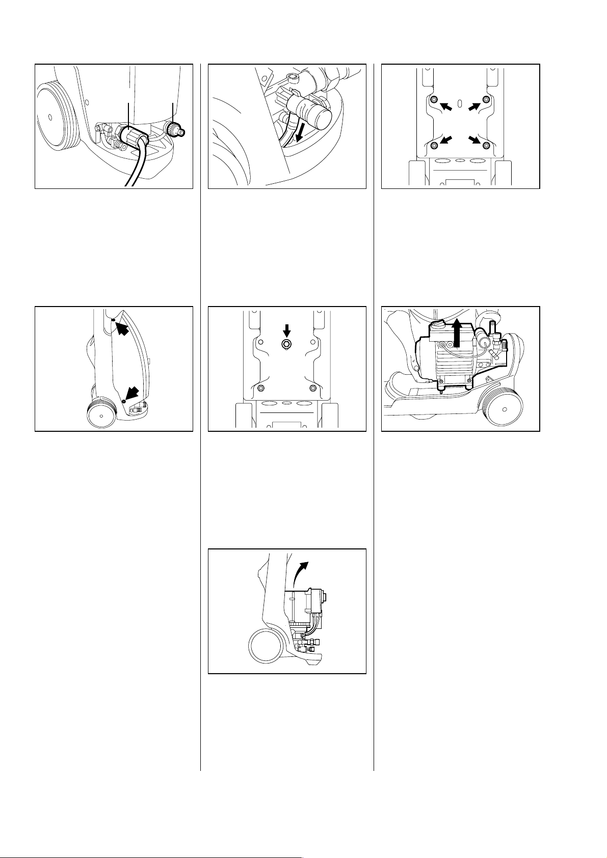
5. HOUSING
5.1 Removing / fitting the
5.2 Removing / installing motor / pump unit
1
•
Unscrew high-pressure hose (1).
•
Unscrew hose connector (2)
from water inlet.
2
621RA001 BL
•
Disconnect detergent intake
hose from metering valve.
- Remove shroud (see 5.1).
- Stand machine upright.
RE 140 K
621RA084 KN
RE 160 K
•
Undo fastening nuts on motor /
pump unit, steadying the bolts at
the same time if necessary.
Hold the machine steady and
ensure that washers are not lost.
- Lay machine in a horizontal
position.
621RA087 KN
•
Undo fastening screws (rear
screw not shown).
•
Remove shroud.
Ensure that spring nuts and
power cable are not lost.
Reassemble parts in reverse order.
621RA002 BL
•
Undo fastening screw on motor /
pump unit, steadying the
machine with the other hand at
thesametime.
•
Lift motor / pump unit out of
frame.
621RA085 KN
•
Lift motor / pump unit out of
frame. Ensure that rubber
buffers, screws and washers
are not lost.
All models
Reassemble parts in reverse order.
621RA086 KN
621RA005 BL
8 RE 140 K, 160 K
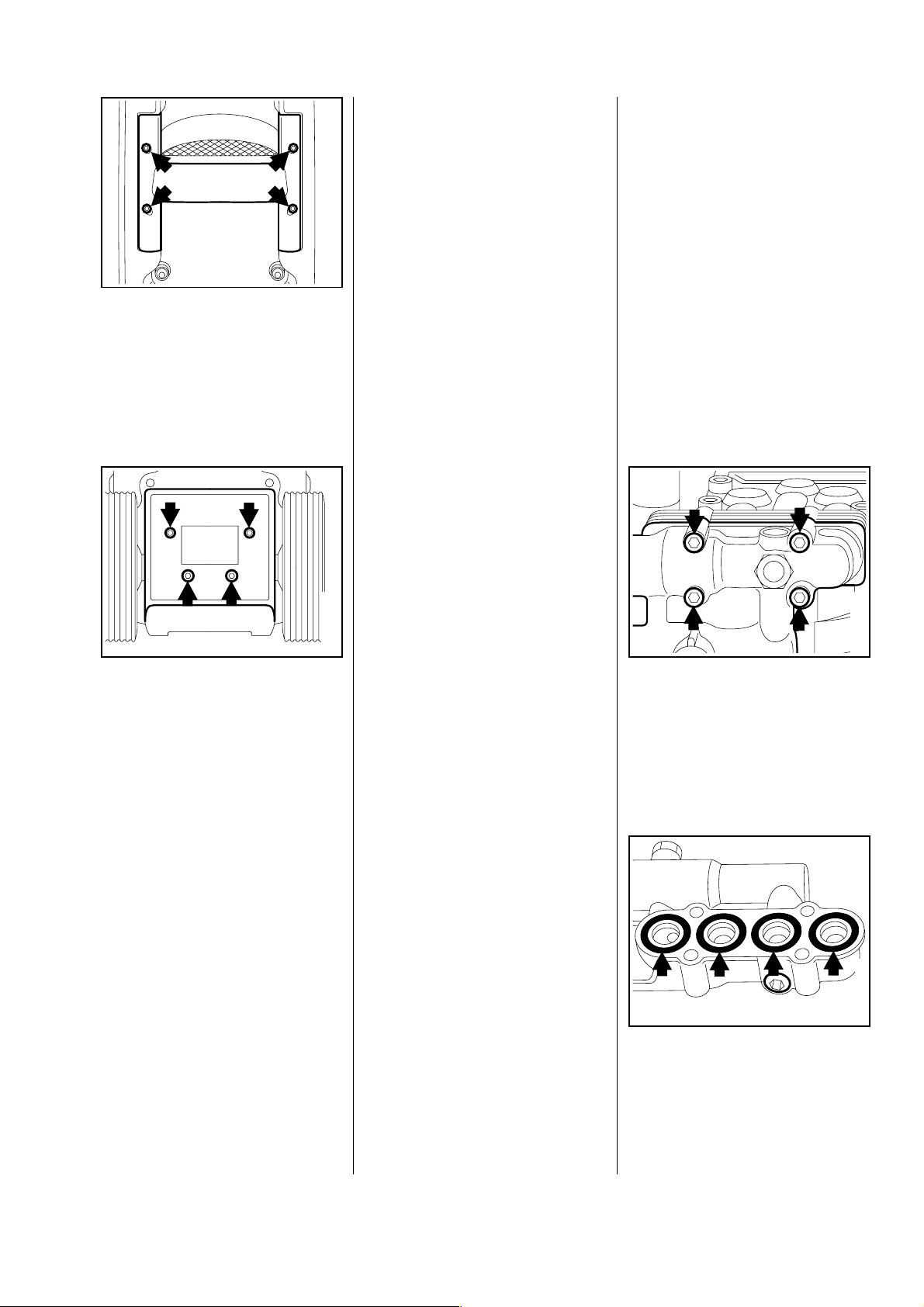
5.3 Chassis 6. SAFETY CONTROL BLOCK
6.1 Removing / installing thesafetycontrolblock
•
Remove handle:
•
Undo fastening screws with
size 5 hexagon socket wrench.
- Remove handle and replace if
necessary.
Important: The O-rings must
always be replaced when carrying
out repair work.
Before assembling the parts, all
moving parts, sealing rings and
screw threads must be thinly
coated with special grease
for high-pressure cleaners
0781 145 3516. Exceptions to
this rule are mentioned where
621RA007 BL
appropriate.
Note: The permissible working
pressure of the machine has been
set on the safety control block by
the manufacturer and must not be
changed. A lead seal is fitted to
the safety control block for this
reason.
The permissible working pressure
must be reset after all repairs and
a new lead seal fitted to the safety
control block.
- Remove shroud (see 5.1) and
motor / pump unit (see 5.2).
Note: The screw plug should only
be removed if leaking.
Remove retainer and shaft:
•
Undo fastening screws with
size 5 hexagon socket wrench.
- Remove retainer and shaft.
Proceed as described for the
high-pressure cleaners of series
STIHL RE 310 K, 340 K and 440 K
for changing wheels.
Replace faulty parts.
Reassemble parts in reverse order.
621RA008 BL
•
Undo fastening screws.
•
Carefully remove the safety
control block. Ensure that the
adjusting screw for the microswitch, O-rings and delivery
valves are not lost.
621RA009 BL
621RA010 BL
•
Replace O-rings.
RE 140 K, 160 K 9
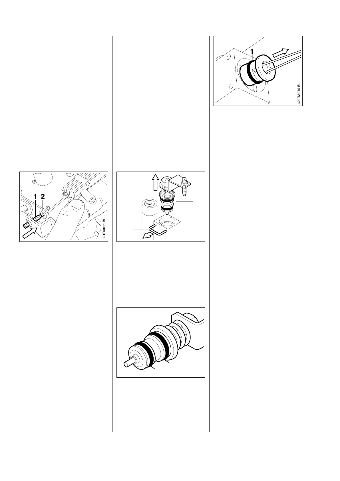
6.2 Removing / installing the control piston
To replace the safety control block
housing:
Remove
-controlpiston(see6.2),
- injector (see 6.4),
- non-return valve (see 6.5) and
- detergent metering valve
(see 6.6).
Reassemble parts in reverse order
and ensure that O-rings are fitted.
- Remove shroud (see 5.1).
•
Draw valve body out of
safety control block with hook
5910 890 2900. Remove ball
and valve-seat insert from safety
control block.
•
Replace O-ring (1) in valve body.
- Examine valve body, ball and
valve-seat insert; replace if necessary.
- Clean valve seat in safety control
2
block.
•
Carefully insert adjusting
screw (1) into opening (2) in
microswitch.
- Turn in fastening screws and
tighten down crosswise with a
torque of 7 Nm.
- Then set the working and cutout
pressure (see 6.3) and refit the
lead seal on the safety control
block.
1
•
Carefully prise off U-bar (1) with
a screwdriver if necessary and
pull it out.
•
Draw control piston (2) out of
safety control block housing.
2
1
Reassemble parts in reverse order.
Note: Thinly coat valve-seat
insert, valve body and O-ring with
621RA013 BL
special grease for high-pressure
cleaners 0781 145 3516 before
fitting them.
- Fit control piston and secure with
U-bar.
•
Then set pressure control
system (see 6.3).
621RA014 BL
•
O-rings (1, 2) on control piston
must always be replaced.
- Examine control piston for signs
of damage and replace
completely if necessary. Ensure
that correct control piston is fitted
(spare parts list).
10 RE 140 K, 160 K
 Loading...