

Page 1

{
STIHL GS 461
Instruction Manual
Page 2

Page 3

Contents
English
Guide to Using this Manual 2
Safety Precautions and Working
Techniques 2
Sample applications 9
Cutting Attachment 11
Mount guide bar and diamond
abrasive chain 11
Tension diamond abrasive chain 13
Check tension of diamond abrasive
Original Instruction ManualPrinted on chlorine-free paper
chain 13
Fuel 14
Fueling 15
Starting / Stopping the Engine 16
Operating Instructions 19
Air Filter System 20
Remove air filter 20
Cleaning the Air Filter 21
Adjusting the Carburetor 21
Spark Arresting Screen in Muffler 22
Spark Plug 23
Replacing the Starter Rope and
Rewind Spring 24
Printing inks contain vegetable oils, paper can be recycled.
Storing the Machine 26
Taking Care of the Guide Bar 26
Checking and Replacing the Chain
Sprocket 27
Maintain and sharpen diamond
abrasive chain 28
Maintenance and Care 29
Minimize Wear and Avoid Damage 31
Main Parts 32
Specifications 33
Special Accessories 34
Maintenance and Repairs 34
Disposal 34
EC Declaration of Conformity 35
Quality Certification 35
Dear Customer,
Thank you for choosing a quality
engineered STIHL product.
This machine has been built using
modern production techniques and
comprehensive quality assurance.
Every effort has been made to ensure
your satisfaction and troublefree use of
the machine.
Please contact your dealer or our sales
company if you have any queries
concerning your machine.
Your
Hans Peter Stihl
{
© ANDREAS STIHL AG & Co. KG, 2012
0458-761-0121-A. VA3.J12.
0000006258_002_GB
GS 461
This instruction manual is protected by copyright. All rights reserved, especially the rights to reproduce, translate and process
with electronic systems.
1
Page 4
English
Guide to Using this Manual
Pictograms
Pictograms that appear on the machine
are explained in this Instruction Manual.
Depending on the machine and
equipment version, the following
pictograms may appear on the machine.
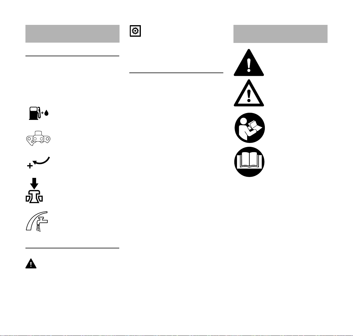
Fuel tank; fuel mixture of
gasoline and engine oil
Direction of chain travel
Tension diamond abrasive chain
Actuate decompression
valve
Water connection, shutoff cock
Symbols in text
WARNING
Warning where there is a risk of an
accident or personal injury or serious
damage to property.
NOTICE
Caution where there is a risk of
damaging the machine or its individual
components.
Engineering improvements
STIHL's philosophy is to continually
improve all of its products. For this
reason we may modify the design,
engineering and appearance of our
products periodically.
Therefore, some changes, modifications
and improvements may not be covered
in this manual.
Safety Precautions and
Working Techniques
Because the chain of a
concrete cutter runs at
very high speeds, special safety precautions
must be observed to
reduce the risk of personal injury.
It is important that you
carefully read the entire
Instruction Manual before
using the machine for the
first time and keep it in a
safe place for future reference. Non-compliance
with the Instruction Manual may cause serious or
even fatal injury.
Observe the national safety regulations
issued, e. g. by the employers' liability
insurance association, social security
institutions, occupational safety and
health authorities or other organizations.
If you have never used a power tool
before: Ask the salesperson or another
expert to explain how to use it safely – or
attend a training course.
Minors should never be allowed to use
the machine – except for young trainees
over the age of 16 when working under
supervision.
Children, animals and bystanders must
remain at a distance.
2
GS 461
Page 5

English
When not using the machine, it must be
laid down in such a way that it does not
endanger anyone. Ensure that the
machine cannot be used without
authorization.
The user is responsible for accidents or
risks involving third parties or their
property.
The machine should only be provided or
loaned to people familiar with this model
and its operation. The Instruction
Manual should always be handed over
with the machine.
Use of machines that emit noise may be
restricted in terms of time by national
and/or on-site, local regulations.
The machine may only be operated by
people who are fit, in good physical
health and in good mental condition.
If you have any condition that might be
aggravated by strenuous work, check
with your doctor before operating a
machine.
If you have a pacemaker: The ignition
system of your machine produces an
electromagnetic field of very low
intensity. An effect on individual
pacemaker types cannot be excluded
entirely. STIHL recommends that you
consult your doctor and the
manufacturer of your pacemaker in
order to avoid health hazards.
Anyone who has consumed alcohol,
medicines affecting their ability to react
or drugs must not operate the machine.
Postpone the work if the weather is bad
(rain, snow, ice, wind) – higher risk of
accidents!
The machine may only be used for
cutting.
The machine must not be used for any
other purposes – risk of injury!
It is not suitable for cutting wood or
wooden objects.
Asbestos dust is extremely toxic - the
machine must therefore never be used
to cut asbestos!
Only use tools, guide bars, diamond
abrasive chains or accessories that
have been approved by STIHL for this
machine or which are technically
equivalent. Contact a servicing dealer if
in doubt. Only use high-quality tools or
accessories. Otherwise there may be a
risk of accidents or damage to the
machine.
STIHL recommends the use of genuine
STIHL guide bars, diamond abrasive
chains, chain sprockets and
accessories. These have been
optimized for the product and the user's
requirements.
Never modify the machine in any way,
as this could be extremely dangerous.
STIHL excludes all liability for personal
injury and damage to property caused
while using unauthorized attachments.
Do not use high-pressure cleaners to
clean the machine. The hard water jet
can damage parts of the machine.
Clothing and equipment
Wear proper protective clothing and
equipment.
Clothing must be sturdy
and snug-fitting, but allow
complete freedom of
movement. Wear snug
fitting clothing – an overall, not a loose-fitting
jacket.
Do not wear clothing that could become
trapped in moving parts of the machine
– no scarves, no neckties, no jewelry.
Long hair must be tied up and covered.
Wear safety boots with
steel toe caps and nonslip soles.
Wear a hard hat wherever there is any risk of
falling objects. Wear goggles to protect the eyes
against flying objects.
Wear "personal" hearing
protection – e. g., ear
defenders.
A face mask alone is not sufficient to
protect the eyes.
Dust (e. g., crystalline material from the
object being cut), fumes and smoke may
be produced while cutting - health
hazard!
Always wear a dust mask if dust is
generated.
If fumes or smoke are anticipated (e. g.,
when cutting composite materials), wear
respiratory protection.
Wear sturdy gloves.
GS 461
3
Page 6
English
STIHL can supply a comprehensive
range of protective clothing and
equipment.
Transporting the machine
Always stop the engine and attach the
chain scabbard.
Carry the machine only by the top
handle – guide bar towards the rear –
with the hot muffler facing away from the
body.
Avoid touching hot parts of the machine,
especially the surface of the muffler –
risk of burns!
In vehicles: Properly secure your
machine to prevent turnover, damage
and fuel spillage.
Refueling
Gasoline is an extremely
flammable fuel – keep
clear of naked flames and
fire – do not spill any fuel
– no smoking.
Switch off the engine before refueling.
Never refuel the machine while the
engine is still hot – the fuel may spill over
– risk of fire!
Open the fuel filler cap carefully so that
any excess pressure is relieved
gradually and fuel does not splash out.
The machine may only be refueled in a
well ventilated place. Clean the machine
immediately if fuel is spilled. Change
your clothes immediately if they are
contaminated with fuel.
Dust may collect on the engine unit,
particularly around the carburetor. If the
dust is soaked with gasoline, it may
catch fire. For this reason, ensure that
the dust is always removed.
Check for fuel leakage
while refueling and during
operation. Never start the
engine if fuel has been
spilled or is leaking –
Fatal burns may result!
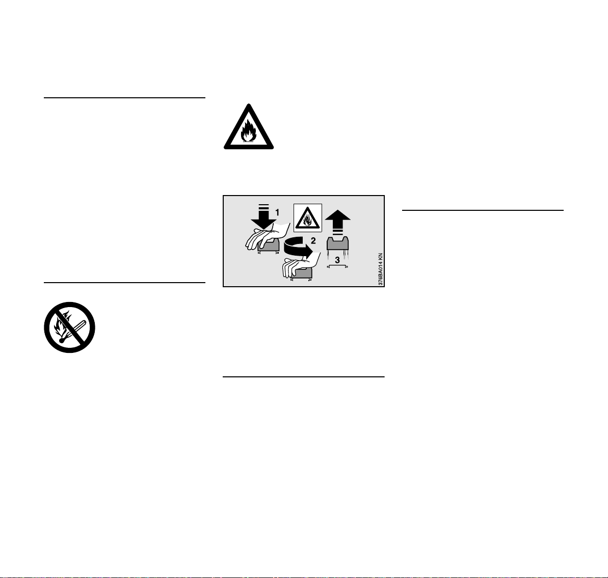
Bayonet filler cap
Never use a tool to open or close the
bayonet filler cap. This could damage
the cap and cause fuel to leak out.
Secure the bayonet filler cap tightly after
refueling.
Diamond abrasive chain
The diamond abrasive chain, guide bar
and chain sprocket must match each
other and your concrete cutter.
Use only approved diamond abrasive
chains. If unauthorized chains are used,
aggressive cutting cannot be ruled out.
This may lead to uncontrolled and
exceedingly dangerous reaction forces
(kickback) in the machine – risk of fatal
injuries!
Only use diamond abrasive chain for the
specified materials, observe diamond
abrasive chain codes.
Always cut with water.
Before fitting used diamond abrasive
chains, check that they are not cracked,
chipped, check also that there are no
damaged or missing segments, signs of
overheating (discoloration).
Never use diamond abrasive chains that
are cracked or have chipped segments.
Visit your servicing dealer.
Before starting
Check that concrete cutter is properly
assembled and in good condition – refer
to appropriate chapters in the Instruction
Manual:
– Check fuel system for leaks,
especially the visible parts, e. g.,
filler cap, hose connections, fuel
pump. Do not start the engine if
there are leaks or damage – risk of
fire! Have the machine repaired by a
servicing dealer before using it
– functional, front hand guard
– Check chain sprocket
– Sprocket nose moves easily
– Correctly mounted guide bar
– The diamond abrasive chain must
be suitable for the material to be cut.
It must be in good condition and
fitted correctly (direction of running).
– Correctly tensioned diamond
abrasive chain
4
GS 461
Page 7

English
2411BA046 KN
– The throttle trigger and throttle
trigger lockout must move easily –
throttle trigger must return
automatically to the idle position
when released
– Master control lever can be moved
to STOP or 0
– Check that the spark plug boot is
secure. A loose boot can lead to
flying sparks which may ignite the
escaping fuel/air mixture – risk of
fire!
– Never attempt to modify the controls
or safety devices
– Keep the handles dry and clean,
free from oil and dirt – important for
safe control of the concrete cutter
The concrete cutter should only be used
if it is in full working order – risk of
accident!
Starting the engine
Move at least 3 meters away from the
place at which the machine was refueled
and never start the machine in enclosed
spaces.
The machine may only be used on level
ground. Ensure a firm and secure
footing and hold the machine firmly. The
diamond abrasive chain must not touch
any objects or the ground and must not
be in the cut, because it may begin to
rotate when the machine is started.
The machine is operated by only one
person. There should not be any other
person within the working area, not even
when starting the machine.
Do not drop-start the engine – start as
described in the Instruction Manual.
Before starting, open the shut-off valve
completely and ensure a supply of water
to the diamond abrasive chain – do not
allow diamond abrasive chain to run dry.
Holding and guiding the machine
Always hold the machine firmly with both
hands: Right hand on the rear handle –
even if you are left-handed. To ensure
reliable control, wrap your thumbs tightly
around the handlebar and handle.
The object that is to be cut must be
positioned firmly; always guide the
machine to the workpiece – never vice
versa.
During work
Ensure you always have a firm and safe
footing.
In the event of impending danger or in
an emergency, switch off the engine
immediately by moving the master
control lever to STOPor0.
The machine is operated by only one
person. There should not be any other
person within the working area.
Use extreme caution with openings,
recesses, etc., someone could be
standing behind them – look
beforehand.
Never let the machine run unattended.
When the engine is running: The
diamond abrasive chain continues to run
for some time after the throttle trigger
has been released – Risk of injury due to
coasting effect!
Beware of slipping on ice, water, snow
or uneven ground!
Never work on a ladder or on any other
unsteady support. Do not work above
shoulder height and never operate the
machine with one hand - risk of
accidents!
Ensure that the working area is clear –
watch out for obstacles, holes and pits.
Do not work alone – keep within calling
distance of others in case help is
needed.
More care and attention than usual are
required when wearing ear protection –
warning sounds (shouts, alarms, etc.)
cannot be heard properly.
Take breaks in due time in order to
prevent tiredness and exhaustion – risk
of accidents!
Keep easily combustible materials away
from hot exhaust gases and hot mufflers
– risk of fire! Mufflers with catalytic
converters can become especially hot.
GS 461
5
Page 8
English
2411BA001 KN
A
2411BA002 KN
B
Your power tool produces
toxic exhaust fumes as
soon as the engine is
running. These gases
may be colorless and
odorless and may contain
unburnt hydrocarbons
and benzene. Never run
the engine indoors or in
poorly ventilated areas,
even if your model is
equipped with a catalytic
converter.
Ensure proper ventilation when working
in trenches, hollows or other confined
areas. Toxic fumes can kill!
If you feel sick, if you have a headache,
vision problems (e.g., your field of vision
gets smaller), hearing problems,
dizziness or inability to concentrate, stop
work immediately. Such symptoms may
be caused by an excessively high
concentration of exhaust emissions –
risk of accident!
No smoking when working with or near
the machine - risk of fire! Combustible
fuel vapor may escape from the fuel
system.
Examine the diamond abrasive chain
periodically at short intervals, check that
they are not cracked, chipped, check
also that there are no damaged or
missing segments, signs of overheating
(discoloration).
Never use diamond abrasive chains that
are cracked or have chipped segments.
Visit your servicing dealer.
In the event of noticeable changes in
cutting behavior (e. g., increased
vibration, reduced cutting performance),
stop work and eliminate the causes of
the changes.
– Switch off the engine and wait until
the diamond abrasive chain is
stationary
– Check condition and correct tension
of diamond abrasive chain
– Ensure that the cutting blades are
sharp
Never touch the diamond abrasive chain
when the motor is running. If the
diamond abrasive chain becomes
jammed by an object, switch off the
engine immediately before attempting to
remove the object – risk of injury!
To change the diamond abrasive chain,
switch off the engine – risk of injury!
If the machine is subjected to unusually
high loads for which it was not designed
(e. g., heavy impact or a fall), always
check that it is in good condition before
continuing work – refer also to the
section "Before starting". Check the fuel
system for leaks and make sure the
safety devices are working properly.
Never continue using a power tool that is
not in perfect working order. Consult a
servicing dealer if in doubt.
Check for correct idling, so that the
diamond abrasive chain stops moving
when the throttle trigger is released.
Check and/or correct the idle setting
regularly. Have the machine repaired by
a STIHL servicing dealer if the diamond
abrasive chain continues to run
nevertheless.
Reactive forces
The most frequently occurring reactive
forces are pull-in and pushback.
Pull-in (A)
When the diamond abrasive chain on
the bottom of the guide bar –
overbucking – is jammed or encounters
a solid object, the concrete cutter may
suddenly be drawn forward to the
workpiece.
Pushback (B)
When the diamond abrasive chain on
the top of the guide bar – underbucking
– is jammed or encounters a solid object,
the concrete cutter may suddenly be
driven straight back toward the operator.
6
GS 461
Page 9
English
002BA146 KN
2411BA003 KN
– Do not allow the guide bar to
become jammed
– Always be aware that the object to
be cut may move and other factors
may cause the cut to close and jam
the diamond abrasive chain
– The object to be cut must be
secured and supported so that the
cut remains open during and after
cutting
– Do not twist the guide bar in the cut
Working – abrasive cutting
Ensure sufficient water supply to
diamond abrasive chain – do not allow
diamond abrasive chain to run dry.
Always wet cut – regardless of the
material to be cut.
The diamond abrasive chain must be
guided straight in the cut, without
wedging. Never exert lateral pressure on
the diamond abrasive chain.
Do not use the diamond abrasive chain
for lateral grinding or scrubbing.
Do not use the starting throttle position
for cutting. Engine speed cannot be
controlled with the throttle trigger in this
position.
Examine the workplace. Avoid all
danger due to damaged piping or
electrical wiring.
The machine must not be used near
inflammable substances or gases.
Never use the machine to cut inside
pipes, metal troughs or other containers
unless you are absolutely sure that they
do not contain any volatile or
inflammable substances.
Never leave the machine unattended
with the engine running. Switch off the
engine before leaving the machine
(e. g., for a break).
Work calmly and methodically – only
with good lighting and visibility. Do not
endanger others – stay alert at all times.
Make certain that all parts of your body
are well clear of the extended range of
travel of the diamond abrasive chain.
Only pull concrete cutter out of the
object being cut with the diamond
abrasive chain running.
Only use concrete cutter for cutting – no t
for prying or shoveling away objects.
Always decide the cutting direction
before positioning the concrete cutter.
After that, do not change the cutting
direction. Avoid knocks and bumps with
the machine while in the cut – do not
drop the machine into the cut – danger of
breakage!
If cutting performance begins to
deteriorate, check the sharpness of the
diamond abrasive chain, resharpen as
needed. To do this, briefly cut through
abrasive material, e. g., sandstone,
aerated concrete or asphalt.
When working above ground level:
– Always use a lift bucket
– Never use the machine while
standing on a ladder
– Never use the machine in unsteady
locations
– Never cut above shoulder height
– Never use the machine with one
hand
Begin cutting with the concrete cutter at
full throttle.
At the end of the cut, the concrete cutter
is no longer supported by the cutting
attachment in the cut. The machine's
weight must be borne by the user – risk
of loss of control!
Keep water and sludge away from
electric cables - risk of electric shocks!
Vibrations
Prolonged use of the power tool may
result in vibration-induced circulation
problems in the hands (whitefinger
disease).
No general recommendation can be
given for the length of usage because it
depends on several factors.
GS 461
7
Page 10

English
The period of usage is prolonged by:
– Hand protection (wearing warm
gloves)
– Work breaks
The period of usage is shortened by:
– Any personal tendency to suffer
from poor circulation (symptoms:
frequently cold fingers, tingling
sensations).
– Low outside temperatures.
– The force with which the handles
are held (a tight grip restricts
circulation).
Continual and regular users should
monitor closely the condition of their
hands and fingers. If any of the above
symptoms appear (e.g. tingling
sensation in fingers), seek medical
advice.
Maintenance and repairs
The machine must be serviced regularly.
Do not attempt any maintenance or
repair work not described in the
Instruction Manual. All other work should
be carried out by a servicing dealer.
STIHL recommends that maintenance
and repair work be carried out only by
authorized STIHL dealers. STIHL
dealers receive regular training and are
supplied with technical information.
Use only high-quality spare parts.
Otherwise, there may be a risk of
accidents or damage to the machine.
Contact a servicing dealer if in doubt.
STIHL recommends the use of genuine
STIHL spare parts. Such parts have
been optimized for the machine and the
user's requirements.
Before starting any maintenance or
repair work and before cleaning the
machine, always stop the engine – risk
of injury! – Exception: adjustment of
carburetor and idle speed.
To reduce the risk of fire due to ignition
outside the cylinder, move the slide
control to STOP or 0 before turning the
engine over on the starter with the spark
plug boot removed or the spark plug
unscrewed.
Do not service or store the machine near
a naked flame – risk of fire due to the
fuel.
Check fuel cap regularly for tightness.
Use only spark plugs that are in perfect
condition and have been approved by
STIHL – see "Specifications".
Inspect ignition lead (insulation in good
condition, secure connection).
Check that the muffler is in perfect
working condition.
Do not use the machine if the muffler is
damaged or missing – risk of fire! –
Hearing damage!
Never touch a hot muffler – risk of burns!
The condition of the antivibration
elements influences vibration behavior –
inspect antivibration elements
periodically.
Switch off the engine
– to check the chain tension
– to retension the chain
– to change chains
– for remedying malfunctions
8
GS 461
Page 11
English
3.
2411BA004 KN
1.
2.
A
2411BA005 KN
2411BA006 KN
Sample applications
Use diamond abrasive
chain only with water.
Connect concrete cutter
to water supply network
(min. 1.5 bar).
The water introduced is used to cool the
diamond abrasive chain and rinse the
cutting attachment, and for binding dust.
After finishing work, run the concrete
cutter for a few seconds with water and
at operating speed to rinse the cutting
attachment.
If the water pressure or water volume is
too low, this leads to significantly
increased wear and irreparable damage
to the cutting attachment – danger of
breakage!
Objects to be cut
– Must be fully supported
– Must be secured so it cannot roll or
slip off
– Must be prevented from vibrating
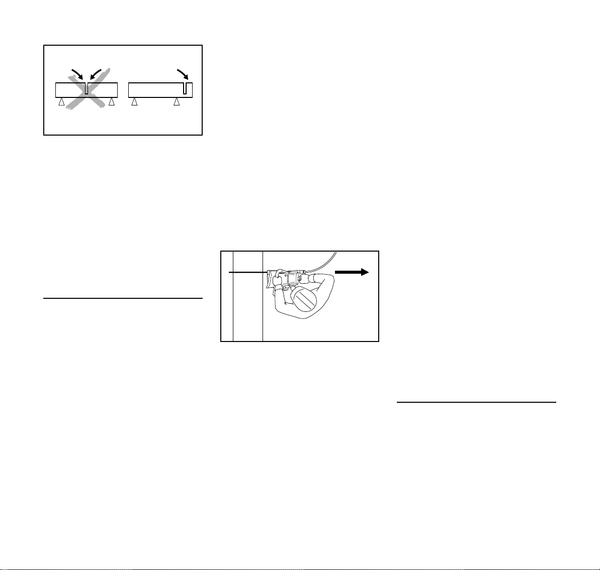
Severed parts
With openings, recesses, etc., the
sequence of the cuts is important.
Always make the last cut so that the
diamond abrasive chain does not
become jammed and so that the
operator is not endangered by the
severed or separated part.
If necessary, use wedges and if
necessary, leave small ridges that hold
the part that is to be separated in
position. Break these ridges later.
Before finally separating the part,
determine:
– how heavy the part is
– how it can move after separation
– whether it is under tension
When breaking out the part, do not
endanger assistants.
Plunge-cutting
Begin cutting with the concrete cutter at
full throttle.
1. Apply the lower portion of the guide
bar nose
2. Swing slowly into the plunge-cutting
position
3. Make the plunge cut very carefully
When making the plunge cut into
existing, narrower joints, proceed with
extreme care.
Cut in several passes
N Mark cutting line (A)
N Work along the cutting line. When
making corrections, do not tilt the
diamond abrasive chain, always
reposition it afresh
GS 461
9
Page 12
English
2411BA007 KN
2411BA008 KN
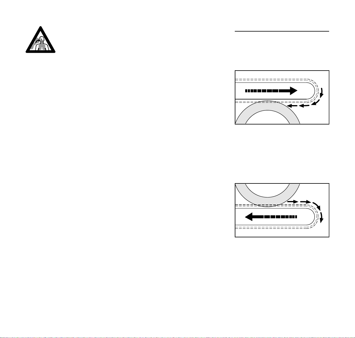
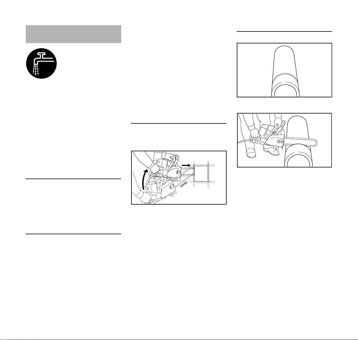
Cutting round and hollow bodies
N Secure pipes, round bodies, etc.
against rolling away
N Mark a cutting line - when
determining the cutting line, avoid
reinforcement, especially in the
direction of the severing cut
N Make the plunge cut very carefully
N Feed with full cutting depth along
the cutting line – for small
corrections of direction, do not tilt
the diamond abrasive chain, but
always position it anew instead – if
necessary, use wedges and if
necessary, leave small ridges that
hold the part that is to be separated
in position. Break these ridges later
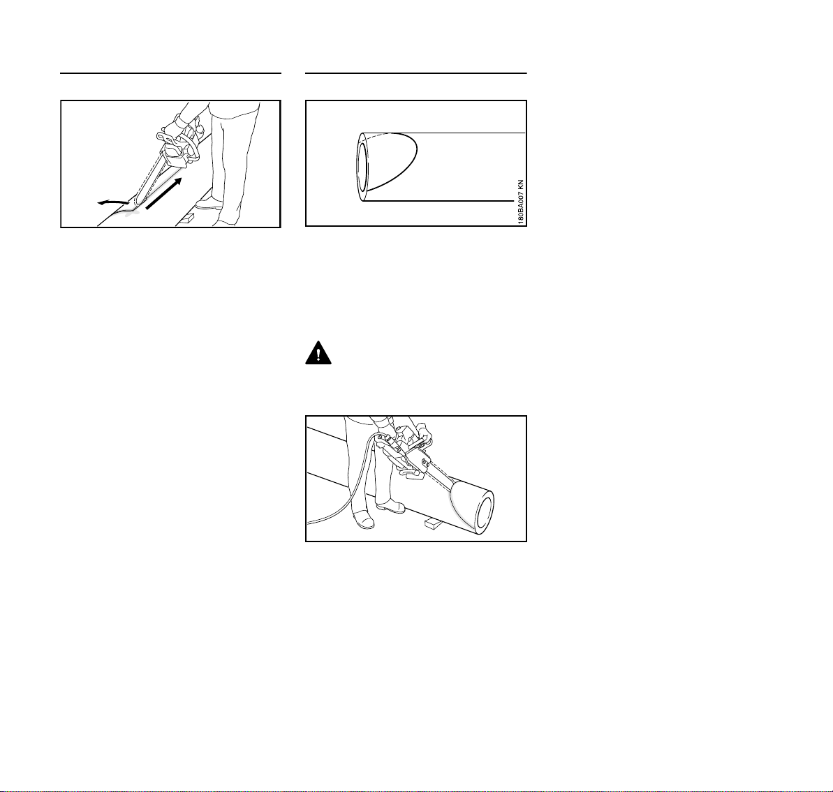
Shaping pipe
N Secure pipes, round bodies, etc.
against rolling away
N Mark a cutting line - when
determining the cutting line, avoid
reinforcement, especially in the
direction of the severing cut
DANGER
Manual cutting along this line requires
particular caution and precision.
always position it anew instead – if
necessary, use wedges and if
necessary, leave small ridges that
hold the part that is to be separated
in position. Break these ridges later
10
N Cut into pipes, round bodies, etc. in
the area at the ends of the cutting
line, so that the material does not
break away
N Make the plunge cut very carefully
at the apex and cut outward on both
sides - feed with full cutting depth
along the cutting line – for small
corrections of direction, do not tilt
the diamond abrasive chain, but
GS 461
Page 13

English
2411BA009 KN
1
2
3
a
t = a : 2
1
1
2411BA011 KN
2
4
2411BA012 KN
3
Cutting Attachment
STIHL is the only manufacturer who
manufactures concrete cutters, guide
bars, diamond abrasive chains and
chain sprockets itself.
Diamond abrasive chain, guide bar and
chain sprocket make up the cutting
attachment.
The cutting attachment that is supplied
has been optimized for the concrete
cutter.
– The pitch (t) of the diamond
abrasive chain (1), chain sprocket
and sprocket nose of the Rollomatic
guide bar must match
– The drive link gauge (2) of the
diamond abrasive chain (1) must be
matched to the groove width of the
guide bar (3)
When pairing components that are not
compatible with each other, the cutting
attachment may become damaged
beyond repair after only a short period of
operation.
Diamond abrasive chain
The correct use of the STIHL diamond
abrasive chain ensures economical use
and avoids accelerated wear.
The STIHL diamond abrasive chain is
suitable for cutting the following
materials:
– Concrete
– Reinforced concrete
– General blocks
– Masonry
– Stone pipes
– Abrasive stone*, e. g. asphalt and
bricks (sandstone)
– Hard stone*, granite*
– ductile cast iron pipes*
*) Restrictions on power and service life
are possible
Do not cut any other materials – risk of
accident!
Chain scabbard
The product contents includes a chain
scabbard that is suitable for the bar and
chain.
Mount guide bar and
diamond abrasive chain
Removing the chain sprocket cover
N Unscrew nuts (1) from the studs –
nuts are fastened to the chain
sprocket cover so that they are
secured against loss
N Remove chain sprocket cover (2)
N Turn the screw (3) to the left until
the tensioner slide (4) butts against
the left end of the housing slot
GS 461
11
Page 14

English
2411BA013 KN
4
1
1
2411BA0014 KN
4
1
1
2411BA049 KN
Fit diamond abrasive chain
N Fit the diamond abrasive chain
starting at the nose of the guide bar
N Position the guide bar over the
bolts (1) – align drive links so that
the position lines up with the symbol
(arrow)
WARNING
If the drive links are not directionally
aligned one behind the other correctly,
the diamond abrasive chain and chain
sprocket will be damaged beyond repair.
N Position the right locating hole (2)
over the peg of the tensioner slide –
simultaneously place the diamond
abrasive chain over the sprocket
wheel (3)
N Turn screw (4) to the right until there
is very little diamond abrasive chain
sag on the underside of the bar and
the lugs of the drive links engage in
the bar groove
N Refit the chain sprocket cover – and
then screw on the nut by hand until
it is fingertight
N Go to chapter "Tensioning the
diamond abrasive chain"
Moving the guide bar
Only move the guide bar if the diamond
abrasive chain cannot be tensioned
properly.
N Removing the chain sprocket cover
N Remove guide bar with diamond
abrasive chain
N Fit the diamond abrasive chain
starting at the nose of the guide bar
WARNING
If the drive links are not directionally
aligned one behind the other correctly,
the diamond abrasive chain and chain
sprocket will be damaged beyond repair.
N Position the left locating hole (5)
over the peg of the tensioner slide –
simultaneously place the diamond
abrasive chain over the sprocket
wheel (3)
N Turn screw (4) to the right until there
is very little diamond abrasive chain
sag on the underside of the bar and
the lugs of the drive links engage in
the bar groove
N Refit the chain sprocket cover – and
then screw on the nuts by hand until
they are fingertight
N Go to chapter "Tensioning the
diamond abrasive chain"
12
N Position the guide bar over the
bolts (1) – align drive links so that
the position lines up with the symbol
(arrow)
GS 461
Page 15

English
1
2411BA0015 KN
2411BA0045 KN
a
2411BA016 KN
Tension diamond abrasive
chain
For retensioning during operation:
N Switch off the engine
N Put on protective gloves
N Loosen nuts
N Raise the guide bar at the nose
N Use the screwdriver to turn the
screw (1) to the right until the
distance (a) = approx. 5 mm
If the distance (a) = approx. 5 mm
cannot be set due to an elongated
diamond abrasive chain, move guide bar
– see installing "guide bar and diamond
abrasive chain".
N Raise the guide bar further and
tighten the nuts securely
N Check tension of diamond abrasive
chain – diamond abrasive chain can
be pulled across the guide bar by
hand
A new diamond abrasive chain must be
retensioned more frequently than one
that has been in use already for an
extended period.
N Check chain tension frequently –
see "Operating Instructions"
Check tension of diamond
abrasive chain
N Switch off the engine
N Diamond abrasive chain can sag a
maximum of a = 15 mm
N Retension diamond abrasive chain
if necessary – see "Tensioning the
diamond abrasive chain".
If the diamond abrasive chain sags too
much, this leads to significantly
increased wear of the cutting
attachment.
A new diamond abrasive chain must be
retensioned more frequently than one
that has been in use already for an
extended period.
N Check chain tension frequently –
see "Operating Instructions"
GS 461
13
Page 16

English
Fuel
The engine requires a mixture of
gasoline and engine oil.
WARNING
Avoid direct skin contact with and
breathing in of gasoline fumes.
STIHL MotoMix
STIHL recommends using STIHL
MotoMix. This pre-blended fuel is free of
benzene and lead, stands out because
of a high octane rating, and always
provides the proper mixing ratio.
STIHL MotoMix is blended with STIHL
HP Ultra two-stroke engine oil for
maximum engine life.
MotoMix is not available in all markets.
Mixing fuel
NOTICE
Unsuitable fuels or a mixing ratio that
deviates from the specification can lead
to severe engine damage. The engine,
seals, fuel lines and fuel tank may be
damaged if poor quality gasoline or
engine oil is used.
Gasoline
Use only high-quality gasoline with an
octane rating of at least 90 ROC –
leaded or unleaded.
Unleaded gasoline must be used in
machines equipped with a catalytic
converter.
NOTICE
Using multiple tankfuls of leaded
gasoline can substantially reduce the
effectiveness of the catalytic converter.
Gasoline with an alcohol component
exceeding 10% can cause impaired
engine performance in engines with
manually adjustable carburetors and
thus should not be used in these
engines.
Engines with M-Tronic deliver full engine
performance using gasoline with an
alcohol component of up to 25% (E25).
Engine oil
Use only high-quality two-stroke engine
oil – ideally STIHL HP, HP Super or
HP Ultra two-stroke engine oil, as they
are specially engineered for STIHL
engines. HP Ultra ensures maximum
performance and engine life.
The engine oils are not available in all
markets.
Only STIHL two-cycle engine oil 1:50
may be used to produce the fuel mixture
for machines with a catalytic converter.
Mixing ratio
for STIHL two-cycle engine oil 1:50;
1:50 = 1 part oil + 50 parts gasoline
Examples
Quantity of
gasoline
Liters Liters (ml)
1 0.02 (20)
5 0.10 (100)
10 0.20 (200)
15 0.30 (300)
20 0.40 (400)
25 0.50 (500)
N Pour oil into an approved safety fuel
canister first, then add gasoline and
mix thoroughly
Storing fuel mixture
Store in approved safety fuel canisters
only in a dry, cool and secure place
protected against light and sunlight.
Fu el m ixture a ges – mix only as much as
needed for a few weeks. Do not store
fuel mixture for longer than
three months. The fuel mixture can
become unusable faster if exposed to
light, sunlight or low or high
temperatures.
N Shake the canister containing the
fuel mixture thoroughly before
refueling
WARNING
Pressure can build up inside the canister
– open carefully.
N The fuel tank and the canister in
which fuel mixture is stored should
be cleaned thoroughly from time to
time
STIHL two-cycle engine
oil 1:50
14
GS 461
Page 17

English
2411BA017 KN
2.
1.
2411BA018 KN
2.
1.
Residual fuel and the liquid used for
cleaning must be disposed of in
accordance with regulations and without
harming the environment!
Fueling
Preparing the machine
N Before fueling, clean the filler cap
and the area around it so that dirt
cannot fall into the tank
N Always position the machine so that
the filler cap is facing upwards
WARNING
Never use a tool to open the bayonet
filler cap. This could damage the cap
and cause fuel to leak out.
Opening the twist lock
Refuel
Take care not to spill fuel while fueling
and do not overfill the tank. STIHL
recommends use of the STIHL filling
system for fuel (special accessory).
Closing the filler cap
N Fit the cap and turn it until it
engages in the bayonet catch
N Press the cap down as far as
possible with your hand and turn it
clockwise (approx. 1/8 of a turn)
until it engages properly
GS 461
N Press the filler cap down as far as
possible by hand, then turn it
counterclockwise (approx. 1/8 turn)
and remove
15
Page 18

English
2411BA019 KN
STOP
0
001BA140 KN
Changing the fuel pickup body every
year
N Drain the fuel tank
N Pull the fuel pickup body out of the
tank with a hook and disconnect it
from the hose
N Connect a new fuel pickup body to
the hose
N Return the fuel pickup body to the
tank
Starting / Stopping the
Engine
The four positions of the Master Control
lever
STOP or 0 – engine off – ignition is
switched off
Run F – engine is running or can start
Warm start n – this position is for
starting the warm engine
Cold start l – this position is for starting
the cold engine
To set the Master Control lever to warm
start n, first set it to cold start l, then
push the Master Control lever into the
warm start n position.
Changing to warm start n is only
possible from the cold start l position.
When the throttle trigger is squeezed,
the Master Control lever returns from
warm start n to run F.
To switch off the engine, set the master
control lever to STOP or 0.
Position cold start l
– If the engine is cold
– If the engine stalls during opening of
throttle after starting
– If the fuel tank has run empty
(engine stalled out)
Position warm start n
– If engine is warm (once the engine
has been running for approx. one
minute)
– When the engine has fired for the
first time
– After ventilation of the combustion
chamber, if the engine was flooded
16
Adjusting the Master Control lever
The throttle trigger lockout and throttle
trigger must be pressed simultaneously
to adjust the Master Control lever from
run F to cold start l.
GS 461
Page 19

English
2411BA025 KN
2411BA020 KN
0001BA021 KN
Connect concrete cutter to water supply
network
N Connect concrete cutter to water
supply network (min. 1.5 bar)
N Before starting, open shut-off valve
(arrow) completely
Hold concrete cutter
There are two ways to hold the concrete
cutter during starting.
On the ground
N Place the concrete cutter securely
on the ground – assume a steady
stance- the diamond abrasive chain
must not touch any objects or the
ground
N Press the concrete cutter firmly
against the ground, holding the front
handle with your left hand, thumb
wrapped round the handle
N Place your right foot into the rear
handle
Between the knees or thighs
N Clamp the rear handle between the
knees or thighs
N Grip the handlebar firmly with the
left hand – thumb wrapped around
the handlebar
GS 461
17
Page 20

English
2411BA022 KN
2411BA023 KN
2
1
2411BA024 KN
STOP
Starting
N With the right hand, pull the starter
grip slowly until you feel it engage –
and then give it a brisk strong pull –
simultaneously press down on the
handlebar – do not pull the starter
rope out all the way – risk of
breakage! Do not let the starter grip
snap back – guide it vertically back
into the housing so that the starter
rope can rewind properly
Starting the concrete cutter
Decompression valve
N Press the button, the
decompression valve will be
opened
The decompression valve is closed
automatically when the engine fires for
the first time. For this reason, press the
button again before each additional
starting attempt.
DANGER
There must not be anyone within the
swivel range of the concrete cutter.
N Simultaneously press the throttle
trigger lockout (2) and throttle
trigger (3) – set the master control
lever
Position cold start l
– If engine is cold (even if the engine
has stalled during opening of
throttle after starting)
Position warm start n
– If engine is warm (once the engine
has been running for approx. one
minute)
N Hold and start the concrete cutter
Before starting, open the shut-off valve
completely and ensure a supply of water
to the diamond abrasive chain – do not
allow diamond abrasive chain to run dry.
18
GS 461
Page 21

English
1
2411BA026 KN
STOP
2
1
2411BA027 KN
STOP
When the engine has turned over for the
first time
N Move the Master Control lever (1) to
the position warm start n
N Press the button on the
decompression valve
N Hold and continue cranking the
concrete cutter
Once the engine is running
N Blip the throttle trigger (2); the
Master Control lever (1) jumps to
run F and the engine begins to idle
The concrete cutter is now ready for use.
At very low temperatures
N Let the engine warm up briefly with
the throttle slightly open
GS 461
Switch off the engine
N Set master control lever to STOP or
0
If the engine does not start
The Master Control lever was not
returned to its "warm start" position n in
time when the engine turned over for the
first time and has now flooded.
N Remove the spark plug - see "Spark
plug"
N Dry the spark plug
N Set master control lever to STOP or
0
N Crank the engine several times with
the starter – to clear the combustion
chamber
N Reinstall the spark plug – see
"Spark plug"
N Set the Master Control lever to
warm start n – even if the engine is
cold
N Restart the engine
Wet filter
N Dry wet filter if necessary – do not
expose to extreme heat
N If the filter is very dirty, clean the
filter thoroughly – see "Cleaning the
air filter"
Operating Instructions
During the break-in period
A factory new machine should not be run
at high revs (full throttle off load) for the
first three tank fillings. This avoids
unnecessarily high loads during the
break-in period. As all moving parts
have to bed in during the break-in
period, the frictional resistances in the
shortblock are greater during this period.
The engine develops its maximum
power after about 5 to 15 tank fillings.
During work
CAUTION
Always work with water.
CAUTION
Do not make the mixture leaner to
achieve an apparent increase in power –
this could damage the engine – see
"Adjusting the Carburetor".
Check chain tension frequently
The diamond abrasive chain stretches
and begins to sag. The drive links on the
underside of the bar must not come out
of the bar groove by more than 15 mm –
the diamond abrasive chain may
otherwise jump off the bar – retension
the diamond abrasive chain – see
"Tensioning the diamond abrasive
chain".
19
Page 22

English
2411BA030 KN
2411BA031 KN
If the diamond abrasive chain sags too
much, this leads to significantly
increased wear of the diamond abrasive
chain and chain sprocket – retension the
diamond abrasive chain – see
"Tensioning the diamond abrasive
chain".
A new diamond abrasive chain must be
retensioned more frequently than one
that has been in use already for an
extended period.
After a long period of full-throttle
operation
After a long period of full-throttle
operation, allow engine to run for a while
at idle speed so that the heat in the
engine can be dissipated by flow of
cooling air. This protects enginemounted components (ignition,
carburetor) from thermal overload.
After finishing work
Short-term storage
Wait for engine to cool down. Keep the
machine with a full tank of fuel in a dry
place, well away from sources of
ignition, until you need it again.
Clean and dry guide bar and diamond
abrasive chain, and spray with STIHL
multispray – in particular the bearing of
the sprocket nose – corrosion protection.
Do not spray engine unit!
Air Filter System Remove air filter
When dry, STIHL filters attain a long
service life.
N Always use STIHL filters dry
Fouled air filters will impair engine
performance, increase fuel consumption
and make the machine more difficult to
start.
N Turn screw plug above the rear
handle in the direction of the arrow
and remove filter cover – screw plug
is secured in the filter cover
N Detach the air filter
Do not remove and clean the auxiliary
filter.
Long-term storage
See "Storing the machine"
20
GS 461
Page 23

Cleaning the Air Filter Adjusting the Carburetor
3443BA001 KN
3443BA002 KN
English
If there is a noticeable loss of engine
power:
N Dry wet air filter if necessary – do
not expose to extreme heat
N If the air filter is very dirty, clean the
filter thoroughly
Thorough filter cleaning
N Wash the air filter in STIHL special-
purpose cleaner (special
accessory) or a clean, nonflammable cleaning liquid (e. g.,
warm soapy water) – rinse the air
filter from inside to out under a water
flow – do not use high-pressure
washers
N Dry the air filter – do not expose to
extreme heat, do not dry with
compressed air
N Do not oil the air filter
N Reinstall air filter
Always replace a damaged air filter.
Basic information
The carburetor comes from the factory
with a standard setting.
The carburetor has been adjusted for
optimum performance and fuel
efficiency in all operating states.
The adjusting screws on this carburetor
can only be set within narrow limits.
The ignition module limits the maximum
speed. It is therefore not possible to
increase the maximum speed by further
turning the high speed screw (H) in the
clockwise direction (making the mix
leaner).
NOTICE
If you make the setting too lean it will
increase the risk of engine damage
through lack of lubrication and
overheating.
Standard setting
N Turn the high speed screw (H)
counterclockwise as far as possible
(max. 3/4 turn)
N Turn the low speed screw (L)
clockwise – as far as possible – then
back off 1/4 turn
Setting the idle speed
Before starting, open the shut-off valve
completely and ensure a supply of water
to the diamond abrasive chain – do not
allow diamond abrasive chain to run dry.
Engine stops when idling or diamond
abrasive chain rotates at idle speed
GS 461
N Switch off the engine
N Check the air filter – clean or replace
it if necessary
N Check the spark arresting screen in
the muffler (present only in some
countries) – clean or replace it if
necessary
N Check standard setting
N Turn the idle speed adjusting
screw (LA) clockwise until the
diamond abrasive chain begins to
run – then turn it back 1 1/2 turns.
21
Page 24

English
3443BA003 KN
3443BA009 KN
1
3
2
3443BA010 KN
WARNING
If the diamond abrasive chain continues
to keep rotating in idle even after
adjustment, have the concrete cutter
checked by a servicing dealer.
Speed erratic when idling; poor
acceleration (despite low speed
screw = 1/4)
N Idle speed setting is too lean – turn
the low speed adjusting screw (L)
counterclockwise until the engine
runs and accelerates smoothly
Whenever the low speed adjusting
screw (L) has been adjusted, it is usually
also necessary to readjust the idle
speed adjusting screw (LA).
NOTICE
After descending from a high altitude,
restore the carburetor setting to the
standard setting.
If you make the setting too lean it will
increase the risk of engine damage
through lack of lubrication and
overheating.
Spark Arresting Screen in
Muffler
In some countries, the muffler is fitted
with a spark arresting screen.
N If engine performance deteriorates,
check the spark arresting screen in
the muffler
N Let the muffler cool down
N Remove four screws
N Remove exhaust casing (1) of the
muffler
Correcting the carburetor setting for use
at high altitudes
The setting may have to be marginally
corrected if engine performance is
unsatisfactory at high altitudes:
N Check standard setting
N Let the engine warm up
N Turn the high speed adjusting
screw (H) slightly clockwise (leaner)
– max. up to the stop
22
N Bend back the retaining lugs (2)
N Pull out spark arresting screen (3)
N Clean the dirty spark arresting
screen, replace if damaged or
heavily carbonized
N Refit the spark arresting screen in
reverse order of steps
GS 461
Page 25

Spark Plug
2411BA030 KN
2
2411BA032 KN
1
000BA039 KN
A
1
000BA045 KN
1
2411BA033 KN
2
N If the engine is down on power,
difficult to start or runs poorly at idle
speed, first check the spark plug.
N Fit a new spark plug after about 100
operating hours – or sooner if the
electrodes are badly eroded. Install
only suppressed spark plugs of the
type approved by STIHL – see
"Specifications".
Remove the spark plug
N Remove coarse dirt from the
machine
N Lift the air baffle (1) up and off
N Unplug spark plug boot (2)
N Unscrew spark plug
Checking the spark plug
English
WARNING
If the spark plug comes with a
detachable adapter nut (1), screw the
adapter onto the thread and tighten it
down firmly to reduce the risk of arcing
and fire.
Installing the spark plug
N Turn screw plug above the rear
handle in the direction of the arrow
and remove filter cover – screw plug
is secured in the filter cover
GS 461
N Clean dirty spark plug.
N Check electrode gap (A) and
readjust if necessary – see
"Specifications".
N Rectify the problems which have
caused fouling of the spark plug.
Possible causes are:
– Too much oil in fuel mix.
– Dirty air filter.
– Unfavorable running conditions.
N Install in the spark plug and tighten
N Press on the spark plug boot (1)
firmly
N Insert the air baffle (2) from above
N Mount filter cover
23
Page 26

English
1
1
1
1
2
3
2411BA034 KN
5
2411BA035 KN
4
6
7
6
213BA019 KN
8
7
2411BA036 KN
Replacing the Starter Rope
and Rewind Spring
Removing the fan housing
N Remove screws (1)
N Push the hand guard (2) upwards
N Pull the bottom of the fan
housing (3) away from the
crankcase and remove downwards
Replacing a torn starter rope
N Carefully press the spring clip (4) off
of the axle with a screw driver or
suitable pliers
N Remove washer (5)
N Remove the pawls (6)
N Remove the rope rotor (7)
N Lever the rope out of the starter
handle with a screwdriver
N Remove the remainder of the rope
from the rotor and starter handle
N Thread the starter handle with the
starter rope from top to bottom
through the rope guide bush (8)
N Pull the starter rope through the
rope rotor (7) and secure it with an
overhand knot
N Coat the bearing bore in the rope
rotor with non-resinous oil
N Slip the rope rotor onto the starter
post (9) – turn it back and forth a
little until the anchor loop of the
rewind spring engages
N Thread a new ElastoStart starter
rope from top to bottom through the
starter handle and
N Press the remaining rope into the
24
handle until the nipple is flush with
the handle
GS 461
Page 27

N Fit the pawls (6) in the rope rotor
5
2411BA037 KN
4
6
6
2411BA038 KN
2411BA039 KN
213BA022 KN
N Place the washer (5) on the starter
post
N Press the spring clip (4) on to the
starter post and over the pegs of the
pawls with a screwdriver or suitable
pliers - note position of spring clip
Tension the rewind spring
N Make a loop in the unwound starter
rope and use it to turn the rope rotor
six full revolutions in the direction of
the arrow
N Hold the rope rotor tight – pull out
the twisted rope and untangle it
N Release the rope rotor
N Slowly let go of the rope so that it
winds on to the rotor. The starter
grip must be drawn firmly into the
rope guide bushing. If it tips
sideways: increase the spring
tension by another turn.
N It must be possible to turn the rope
rotor another half-turn when the
rope has been drawn out
completely. If not, the spring has
been tensioned too tightly and may
break! Remove one turn of the rope
from the rotor
N Install the fan housing
N Set master control lever to STOP or
0 and press the remaining rope into
the handle – until the nipple is flush
with the handle
Replacing broken rewind spring
N Remove the rope rotor - see section
"Replacing torn starter rope"
WARNING
The broken pieces of spring may still be
under tension and can spring apart
unexpectedly on removal – risk of injury!
Wear a face shield and protective
gloves.
English
N Undo the screws and remove the
spring housing
N Carefully pry out the broken pieces
of spring with a screwdriver
N Apply a few drops of non-resinous
oil to the new replacement spring
N Position the replacement spring
with frame in the fan housing – the
anchor loop (arrow) must be located
over the retaining lug in the fan
housing
N Apply suitable tools (screwdriver,
punch, etc. ) to the recesses and
push the spring into its seat in the
fan housing – the spring slides out of
the frame holder.
N Remove spring housing, reinstall
the rope rotor, tension the rewind
spring, replace the fan housing and
screw it into place
GS 461
25
Page 28

English
2
3
1
2411BA028 KN
Storing the Machine Taking Care of the Guide Bar
If the machine is to remain out of use for
approx. 3 months or more
N Drain and clean the fuel tank in a
well ventilated place
N Dispose of fuel in accordance with
the regulations and having regard
for the environment
N Run the engine until the carburetor
is dry, this helps to prevent the
carburetor diaphragms sticking
together
N Remove, clean and dry diamond
abrasive chain and guide bar, and
spray with STIHL multispray – in
particular the bearing of the
sprocket nose – corrosion
protection.
N Thoroughly clean the machine - pay
special attention to the cylinder fins
and air filter
N Store machine in a safe and dry
place. Protect against unauthorized
use (e. g., by children)
N Flip the guide bar – each time the
chain is changed – to avoid uneven
wear, especially at the sprocket
nose and on the bottom
N Periodically clean the water inlet
hole (1), water outlet channel (2)
and bar groove (3)
N Measure groove depth – using the
measuring tool on the file gauge
(special accessory) – in the area
with the greatest wear
If the groove is not at least 6 mm deep:
N Replace guide bar
Otherwise the drive links will grind
against the base of the groove – tie
straps will not lie against the bar.
If the guide bar runs in the cut:
N Check guide bar for uneven wear
(ridge offset)
N Flip the guide bar, if necessary
remove the bore of the guide bar
with guide bar straightener
26
GS 461
Page 29

English
2411BA040 KN
1
3
2
2411BA041 KN
6
1
5
3
2
4
2411BA042 KN
Checking and Replacing the
Chain Sprocket
N Remove chain sprocket cover,
diamond abrasive chain and guide
bar
Replacing rim sprocket
– If the diamond abrasive chain is
being replaced, also replace the rim
sprocket
– If the wear marks (arrows) are
deeper than 0.5 mm – otherwise the
service life of the diamond abrasive
chain is reduced – use check gauge
(special accessory) to test
Using two diamond abrasive chains in
alternation helps preserve the chain
sprocket.
N Remove cap (1)
N Remove rim sprocket (2)
N Inspect transport profile on the
clutch drum (3) – if there are also
heavy signs of wear, also replace
the clutch drum (3)
Installing rim sprocket
N Fit rim sprocket (2)
N Fit cap (1)
Replacing clutch drum
Installing the clutch drum
N Clean crankshaft stub and needle
cage and lubricate with STIHL
lubricant (special accessory)
N Slip the needle cage onto the
crankshaft stub.
N Fit clutch drum
N Fit rim sprocket
N Refit washer and E-clip on the
crankshaft
N Fit cap
Removing rim sprocket
If only the rim sprocket is removed, the
clutch drum does not need to be
removed.
GS 461
N Remove cap (1)
N Remove rim sprocket (4)
N Use a screwdriver to remove the E-
clip (2)
N Remove washer (3)
N Remove clutch drum (5) with needle
cage (6) from the crankshaft
27
Page 30

English
Maintain and sharpen
diamond abrasive chain
Maintaining the diamond abrasive chain
After finishing work:
N Remove diamond abrasive chain
and guide bar
N Rinse diamond abrasive chain and
guide bar with water
N Dry diamond abrasive chain and
guide bar
N Spray diamond abrasive chain and
guide bar with STIHL multispray – in
particular the bearing of the
sprocket nose – corrosion
protection
Check diamond abrasive chain regularly
N Check the diamond abrasive chain
for cracks and damaged rivets
N Replace damaged or worn chain
components – contact a servicing
dealer
Never use a dull or damaged diamond
abrasive chain – this leads to increased
physical strain, increased vibration load,
unsatisfactory results and increased
wear.
If cutting performance begins to
deteriorate, check the sharpness of the
diamond abrasive chain, resharpen as
needed. To do this, briefly cut through
abrasive material, e. g., sandstone,
aerated concrete or asphalt.
28
GS 461
Page 31

Maintenance and Care
The following information applies under normal operating conditions. The specified intervals must be
shortened accordingly when working for longer than normal or under difficult cutting conditions
(extensive dust, etc.).
before starting work
at the end of work and/or
daily
whenever tank is refilled
weekly
Complete machine
Throttle trigger, throttle trigger lockout, master control lever
Fuel pickup body in fuel tank
Fuel tank clean X
Water supply, chain lubrication check X
Diamond abrasive chain
Guide bar
Chain sprocket check, replace if necessary X
Air filter
Antivibration elements
Cooling air intake slits clean X
visual inspection (condition, leaks) XX
clean X
Checking operation XX
check X
replace XXX
check, pay attention to sharpness XX
Check chain tension, retension if necessary; also
check every 15 minutes while working, retension
if necessary
sharpen X
clean and spray with STIHL multispray X
check (wear, damage, action of sprocket nose) X
clean and spray with STIHL multispray X
flip X
deburr X
replace XX
clean XX
replace X
check XX
have them replaced by a specialist dealer
1)
XX
3)
monthly
yearly
English
if faulty
if damaged
XX
X
as required
GS 461
29
Page 32

English
The following information applies under normal operating conditions. The specified intervals must be
shortened accordingly when working for longer than normal or under difficult cutting conditions
(extensive dust, etc.).
before starting work
at the end of work and/or
daily
whenever tank is refilled
weekly
monthly
yearly
if faulty
Cylinder fins clean XX
Carburetor
Spark plug
All accessible screws, nuts and bolts (not adjusting
2)
screws)
Spark arresting screen (present only in some
countries)
Exhaust bore
Safety information labels replace X
1)
STIHL recommends STIHL servicing dealers
2)
During initial use, tighten the cylinder block screws after 10 to 20 hours of operation
3)
If diamond abrasive chain is mounted or changed
Check idle adjustment – chain must not rotate XX
Set the idle speed X
adjust electrode gap X
replace after 100 hours’ operation
retighten X
1)
check
clean or replace if necessary
decarbonise after 139 hours of operation, subse-
quently after every 150 hours of operation
1)
X
if damaged
as required
X
X
30
GS 461
Page 33

English
Minimize Wear and Avoid
Damage
Observing the instructions in this manual
helps reduce the risk of unnecessary
wear and damage to the power tool.
The power tool must be operated,
maintained and stored with the due care
and attention described in this owner's
manual.
The user is responsible for all damage
caused by non-observance of the safety
precautions, operating and maintenance
instructions in this manual. This includes
in particular:
– Alterations or modifications to the
product not approved by STIHL.
– Using tools or accessories which
are neither approved or suitable for
the product or are of a poor quality.
– Using the product for purposes for
which it was not designed.
– Using the product for sports or
competitive events.
– Consequential damage caused by
continuing to use the product with
defective components.
Maintenance Work
All the operations described in the
"Maintenance Chart" must be performed
on a regular basis. If these maintenance
operations cannot be performed by the
owner, they should be performed by a
servicing dealer.
STIHL recommends that you have
servicing and repair work carried out
exclusively by an authorized STIHL
servicing dealer. STIHL dealers are
regularly given the opportunity to attend
training courses and are supplied with
the necessary technical information.
If these maintenance operations are not
carried out as specified, the user
assumes responsibility for any damage
that may occur. Among other parts, this
includes:
– Damage to the engine due to
neglect or deficient maintenance
(e.g. air and fuel filters), incorrect
carburetor adjustment or
inadequate cleaning of cooling air
inlets (intake ports, cylinder fins).
– Corrosion and other consequential
damage resulting from improper
storage.
– Damage to the machine resulting
from the use of poor quality
replacement parts.
Parts Subject to Wear and Tear
Some parts of the power tool are subject
to normal wear and tear even during
regular operation in accordance with
instructions and, depending on the type
and duration of use, have to be replaced
in good time. Among other parts, this
includes:
– Diamond abrasive chain, guide bar
– Drive components (clutch, clutch
drum, chain sprocket)
– Filters (air, fuel)
– Rewind starter
– Spark plug
– Components of antivibration system
GS 461
31
Page 34

English
1
4
14
16
17
19
7
2411BA043 KN
2
3
5
8
9
10
11
12
13
15
18
20
#
Main Parts
1 Twist lock
2 Spark plug boot
3 Carburetor adjusting screws
4 Water connection, shut-off cock
5 Chain sprocket cover
6 Chain sprocket
7 Chain tensioner
8 Guide bar
9 Diamond abrasive chain
10 Muffler
11 Front hand guard
12 Front handle (handlebar)
13 Decompression valve
14 Starter grip
15 Fuel filler cap
16 Master Control lever
17 Throttle trigger
18 Throttle trigger lockout
19 Rear handle
20 Rear hand guard
# Serial number
32
GS 461
Page 35

English
Specifications
Engine
STIHL single cylinder two-stroke engine
Displacement: 76.5 cm
Bore: 52 mm
Stroke: 36 mm
Engine power to
ISO 7293:
4.3 kW (5.8 HP)
at 9,800 rpm
Idle speed: 2,500 rpm
Engine cut-off
speed: 13,500 rpm
Ignition System
Electronic magneto ignition
Spark plug (resistor
type):
Bosch WSR 6 F,
NGK BPMR 7 A
Electrode gap: 0.5 mm
Fuel System
3
Cutting Attachment (GS 461)
Rollomatic G guide bar
Bar lengths (3/8"
pitch): 40 cm
Groove width: 1.6 mm
3/8" diamond abrasive chain
36 GBM, Type 3210
Pitch: 3/8" (9.32 mm)
Drive link gauge: 1.6 mm
Chain sprockets
7-tooth for 3/8" (rim sprocket)
Sound and vibration levels
When determining sound and vibration
levels, idling and full load are taken into
account in a ratio of 1:6.
For further details concerning
compliance with the Physical Agents
Directive Vibration 2002/44/EC, see
www.stihl.com/vib.
The K-factor in accordance with
Directive 2006/42/EC is 2.5 dB(A) for
the sound pressure level and sound
power level; the K-factor in accordance
with Directive 2006/42/EC is 2.0 m/s
2
for the vibration measurement.
REACH
REACH is an EC regulation and stands
for the Registration, Evaluation,
Authorisation and Restriction of
Chemical substances.
For information on compliance with the
REACH regulation (EC) No. 1907/2006
see www.stihl.com/reach.
All position diaphragm carburetor with
integral fuel pump
Fuel tank capacity: 0.78 L
Weight
dry, without bar and chain: 7.6 kg
GS 461
Sound pressure level L
peq
105 dB(A)
Sound power level L
to ISO 11201
weq
115 dB(A)
Vibration level a
to ISO 19432
hv,eq
Handle,
left
GS 461 4.5 m/s
to ISO 11201
Handle,
right
2
4.0 m/s
2
33
Page 36

English
000BA073 KN
Special Accessories Maintenance and Repairs Disposal
– Check gauges
– STIHL grease
– STIHL filling system for fuel –
prevents spillage or overfilling
during filling
– Guide bar straightener
Ask your STIHL servicing dealer for
current information about this and other
special accessories.
Users of this machine may only carry out
the maintenance and service work
described in this user manual. All other
repairs must be carried out by a
servicing dealer.
STIHL recommends that you have
servicing and repair work carried out
exclusively by an authorized STIHL
servicing dealer. STIHL dealers are
regularly given the opportunity to attend
training courses and are supplied with
the necessary technical information.
When repairing the machine, only use
replacement parts which have been
approved by STIHL for this power tool or
are technically identical. Only use highquality replacement parts in order to
avoid the risk of accidents and damage
to the machine.
STIHL recommends the use of original
STIHL replacement parts.
Original STIHL parts can be identified by
the STIHL part number, the {
logo and the STIHL parts symbol K
(the symbol may appear alone on small
parts).
Observe all country-specific waste
disposal rules and regulations.
Do not throw your STIHL product in the
garbage can. Take the product,
accessories and packaging to an
approved disposal site for environmentfriendly recycling.
Contact your STIHL servicing dealer for
the latest information on waste disposal.
34
GS 461
Page 37

English
000BA025 LÄ
EC Declaration of Conformity
ANDREAS STIHL AG & Co. KG
Badstr. 115
D-71336 Waiblingen
hereby confirms that
Model: Stone cutter
Make: STIHL
Type: GS 461
Serial identification
number: 4252
Displacement: 76.5 cm
conform to the specifications of
Directives 2006/42/EC and
2004/108/EC and have been developed
and built in compliance with the following
standards:
EN ISO 12100, EN 55012,
EN 61000-6-1
The technical documentation has been
retained by:
ANDREAS STIHL AG & Co. KG
Product approval
The year of construction and the serial
number are shown on the machine.
Waiblingen, 03.05.2012
ANDREAS STIHL AG & Co. KG
pp.
3
Quality Certification
All STIHL products comply with the
highest quality standards.
An independent organization has
certified that all products manufactured
by STIHL meet the strict requirements of
the ISO 9001 standard for quality
management systems in terms of
product development, materials
purchasing, production, assembly,
documentation and customer service.
Elsner
Head of Product Group Management
GS 461
35
Page 38

English
36
GS 461
Page 39

Page 40

0458-761-0121-A
englisch
G
www.stihl.com
*04587610121A*
0458-761-0121-A
 Loading...