

Page 1

STIHL FT 250
Instruction Manual2 - 32
Page 2

English
Contents
1 Guide to Using this Manual.........................2
2 Safety Precautions and Working Techni‐
ques............................................................ 3
3 Using the Unit............................................. 9
4 Approved Combinations of Cutting Attach‐
ment, Deflector, Limit Stop and Harness.. 10
5 Mounting the Bike Handle.........................10
6 Adjusting the Throttle Cable......................12
7 Fitting Padding.......................................... 12
8 Mounting the Deflector..............................12
9 Mounting the Cutting Attachment..............13
10 Fuel........................................................... 14
11 Fueling...................................................... 15
12 Fitting the Harness....................................16
13 Starting / Stopping the Engine.................. 20
14 Transporting the Unit................................ 22
15 Operating Instructions...............................22
16 Cleaning the Air Filter............................... 23
17 Adjusting the Carburetor........................... 24
18 Spark Plug................................................ 25
19 Engine Running Behavior......................... 26
20 Lubricating the Gearbox............................26
21 Replacing the Starter Rope and Rewind
Spring........................................................26
22 Storing the Machine.................................. 28
23 Sharpening Metal Cutting Blades............. 28
24 Inspection and Maintenance by User........28
25 Inspections and Maintenance by Dealer...29
26 Maintenance and Care..............................29
27 Minimize Wear and Avoid Damage...........30
28 Main Parts.................................................31
29 Specifications............................................31
30 Maintenance and Repairs......................... 32
31 Disposal.................................................... 32
Dear Customer,
Thank you for choosing a quality engineered
STIHL product.
It has been built using modern production techni‐
ques and comprehensive quality assurance.
Every effort has been made to ensure your satis‐
faction and trouble-free use of the product.
Please contact your dealer or our sales company
if you have any queries concerning this product.
Your
Dr. Nikolas Stihl
1 Guide to Using this Manual
1.1 Pictograms
The meanings of the pictograms attached to the
machine are explained in this manual.
Depending on the model concerned, the follow‐
ing pictograms may be attached to your
machine.
Fuel tank; fuel mixture of gasoline
and engine oil
Operate decompression valve
Manual fuel pump
Operate manual fuel pump
Tube of grease
Intake air: Summer operation
Intake air: Winter operation
Handle heating
1.2 Symbols in text
WARNING
Warning where there is a risk of an accident or
personal injury or serious damage to property.
Original Instruction Manual
0000000795_016_GB
Printed on chlorine-free paper
Printing inks contain vegetable oils, paper can be recycled.
© ANDREAS STIHL AG & Co. KG 2021
0458-262-0121-C. VA0.F21.
NOTICE
Caution where there is a risk of damaging the
machine or its individual components.
1.3 Engineering improvements
STIHL's philosophy is to continually improve all
of its products. For this reason we may modify
2 0458-262-0121-C
Page 3

2 Safety Precautions and Working Techniques English
the design, engineering and appearance of our
products periodically.
Therefore, some changes, modifications and
improvements may not be covered in this man‐
ual.
2 Safety Precautions and
Working Techniques
Some special safety precautions
must be observed to reduce the risk
of personal injury when operating this
power tool because of the very high
speed of its cutting attachment.
It is important you read and under‐
stand the User Manual before com‐
missioning and keep it in a safe place
for future reference. Non-compliance
with the User Manual may cause seri‐
ous or even fatal injury.
Observe all applicable local safety regulations,
e.g. by trade organizations, social insurance
institutions, labor safety authorities etc.
If you have never used a power tool before:
Have your dealer or other experienced user
show you how to operate your machine – or
attend a special course to learn how to operate
it.
Minors should never be allowed to use the
machine – except for apprentices over the age of
16 when working under supervision.
Children, animals and bystanders must remain at
a distance.
When not using the machine, it must be laid
down in such a way that it does not endanger
anyone. Ensure that the machine cannot be
used without authorization.
The user is responsible for avoiding injury to third
parties or damage to their property.
Do not lend or rent your power tool without the
User Manual. Be sure that anyone using it under‐
stands the information contained in this manual.
The use of machines that emit noise may be limi‐
ted to certain hours of the day as specified by
national and/or regional or local regulations.
Anyone operating the machine must be well res‐
ted, in good physical health and in good mental
condition.
If you have any condition that might be aggrava‐
ted by strenuous work, check with your doctor
before operating a machine.
If you have a pacemaker: The ignition system of
your machine produces an electromagnetic field
of very low intensity. This field may interfere with
some pacemakers. STIHL recommends that per‐
sons with pacemakers consult their physician
and the pacemaker manufacturer to reduce any
health risk.
Anyone who has consumed alcohol or drugs or
medicines affecting their ability to react must not
operate a power tool.
Use your power tool only for cutting
and pruning tea plants – not logs.
The machine must not be used for any other pur‐
poses – risk of accidents!
Only use cutting attachments and accessories
that are explicitly approved for this power tool
model by STIHL or are technically identical. If
you have any questions in this respect, consult
your dealer. Use only high quality parts and
accessories. in order to avoid the risk of acci‐
dents and damage to the machine.
STIHL recommends the use of original STIHL
tools and accessories. They are specifically
designed to match the product and meet your
performance requirements.
Never attempt to modify your power tool in any
way since this may increase the risk of personal
injury. STIHL excludes all liability for personal
injury and damage to property caused while
using unauthorized attachments.
Do not use a high-pressure washer to clean the
power tool. The solid jet of water may damage
parts of the unit.
The guard provided with your machine may not
protect the operator from all foreign objects
(gravel, glass, wire etc.) ejected by the revolving
cutting attachment. Ejected objects may also ric‐
ochet and strike the operator.
2.1 Clothing and equipment
Wear proper protective clothing and equipment.
Clothing must be sturdy but allow
complete freedom of movement.
Wear close-fitting clothes such as a
boiler suit, not a loose jacket.
Do not wear clothing which could
become trapped in wood, brush or
moving parts of the machine. Do not
wear a scarf, necktie or jewelry. Tie
up and confine long hair above your
shoulders.
0458-262-0121-C 3
Page 4

262BA029 KN
English 2 Safety Precautions and Working Techniques
Wear safety boots with steel toe caps
and non-slip soles.
WARNING
To reduce the risk of eye injuries,
wear close-fitting safety glasses in
accordance with European Standard
EN 166. Make sure the safety
glasses are a snug fit.
Wear face protection and make sure it is a good
fit. Face protection alone is not sufficient to pro‐
tect the eyes.
Wear "personal" sound protection, e.g. ear
defenders.
Wear a safety hard hat for thinning operations,
when working in high scrub and where there is a
danger of head injuries from falling objects.
Wear sturdy protective gloves made
of a resistant material (e. g. leather).
STIHL can supply a comprehensive range of per‐
sonal protective equipment.
2.2 Transporting the machine
2.3 Refueling
Gasoline is extremely flammable –
keep it away from naked flames – do
not spill any fuel – no smoking.
Always shut off the engine before refueling.
Do not fuel a hot engine – fuel may spill and
cause a fire.
Open the fuel cap carefully to allow any pressure
build-up in the tank to release slowly and avoid
fuel spillage.
Only refuel the machine in a well ventilated
place. If fuel has been spilled, immediately clean
the machine – do not allow your clothes to be
splashed with fuel. If that happens, change your
clothes at once.
After refueling, close the fuel cap as
tightly as possible.
This helps reduce the risk of unit vibrations caus‐
ing an incorrectly tightened fuel cap to loosen or
come off and spill quantities of fuel.
Check for leaks. Do not start the engine if there
is a fuel leak – serious or fatal burns could result!
2.4 Before starting
Check that your power tool is properly assem‐
bled and in good condition – refer to appropriate
chapters in the User Manual:
Check the fuel system for leaks, especially the
–
visible parts, e. g., fuel cap, hose connections,
manual fuel pump (only in machines with a
manual fuel pump). In case of leakage and
damage, do not start the engine – risk of fire!
Have the machine serviced by a dealer before
using it
Use only an approved combination of cutting
Always stop the engine.
Carry the machine hanging on the harness or by
the shaft so that it is balanced.
To reduce the risk of cut injuries, fit transport
guard on the cutting attachment, even when car‐
rying the tool for short distances – see also
"Transporting the Unit".
Avoid touching hot parts of the
machine and gearbox – risk of burns!
By vehicle: When transporting in a vehicle, prop‐
erly secure your machine to prevent turnover,
damage and fuel spillage.
–
attachment, deflector, handle and harness. All
parts must be assembled properly and
securely
Slide control / stop switch must move easily to
–
STOP or 0
Throttle trigger lockout (if installed) and throttle
–
trigger must move easily – the throttle trigger
must return to the idle position automatically
Check that the spark plug boot is secure – a
–
loose boot may cause sparking that could
ignite combustible fumes and cause a fire!
Check cutting attachment for correct and
–
secure assembly and good condition
Check safety devices (e. g., deflector for cut‐
–
ting attachments) for damage and/or wear.
4 0458-262-0121-C
Page 5

262BA048 KN
15m (50ft)
2 Safety Precautions and Working Techniques English
Always replace damaged parts. Never operate
the unit with a damaged deflector
Never attempt to modify the controls or safety
–
devices
Keep the handles dry and clean – free from oil
–
and dirt – this is important for safe control of
the machine
Adjust the harness and handles to suit your
–
height and reach – see "Fitting the Harness".
To reduce the risk of personal injury, do not
operate your machine if it is not in a safe condi‐
tion.
To prepare for emergencies when using a har‐
ness: Practice setting down the machine quickly.
To avoid damage, do not throw the machine to
the ground when practicing.
2.5 Starting the engine
Start the engine at least 3 meters from the fuel‐
ing spot, outdoors only.
Place the unit on firm ground in an open area.
Make sure you have good balance and secure
footing. Hold the unit securely. The cutting
attachment must be clear of the ground and all
other obstructions because it may begin to run
when the engine starts.
Your power tool is a one-person unit. To reduce
the risk of injury from ejected objects, do not
allow other persons within a radius of 15 meters
of your own position – even when starting.
Avoid contact with the cutting attach‐
ment – risk of injury!
2.6 Holding and guiding the machine
Always hold the unit firmly with both hands on
the handles.
Make sure you always have good balance and
secure footing.
Right hand on control handle, left hand on grip
on handlebar.
2.7 While working
Make sure you always have good balance and
secure footing.
In the event of impending danger or in an emer‐
gency, switch off the engine immediately - move
the slide control/stop switch to STOP or 0.
Do not drop-start the power tool –
start the engine as described in the
User Manual. The cutting attachment
runs on for a short while after releas‐
ing the throttle trigger – coasting
effect!
Check engine idling: The cutting attachment
must remain at a standstill when the engine idles
– throttle trigger released.
Keep easily combustible materials (e. g., wood
chips, bark, dry grass, fuel) away from hot
exhaust gases and hot muffler surfaces – risk of
fire!
0458-262-0121-C 5
Within a wide area around the workplace, there
is a risk of accident by ejected objects, therefore
ensure that there is no-one within a 15 m radius
of the machine. This distance must also be main‐
tained in relation to objects (vehicles, window
panes) – risk of property damage! Even at a dis‐
tance over 15 m, danger cannot be ruled out.
Never touch the rotating cutting
attachment – risk of serious injury.
Check that the engine is properly idling so that
the cutting tool will not continue rotating after you
release the throttle trigger.
Check and correct the idle speed setting at regu‐
lar intervals. If the cutting attachment still rotates
at idle speed, have your dealer make proper
Page 6

English 2 Safety Precautions and Working Techniques
adjustments or repairs. STIHL recommends you
have this work done by a STIHL servicing dealer.
Take special care in slippery conditions – damp,
snow, ice, on slopes or uneven ground.
Watch out for obstacles: tree stumps, roots – risk
of tripping or stumbling!
Only work while standing on the ground, never
on a ladder or mobile elevated work platform.
Be particularly alert and cautious when wearing
hearing protection because your ability to hear
warnings (shouts, alarms, etc.) is restricted.
Take breaks when you start getting tired or feel‐
ing fatigue – risk of accidents!
Work calmly and carefully – in daylight conditions
and only when visibility is good. Proceed with
caution, do not put others in danger.
As soon as the engine is running, the
power machine generates toxic
exhaust gas.As soon as the engine is
running, the power machine gener‐
ates toxic exhaust gas. These gases
may be odorless and invisible and
may contain unburned hydrocarbons
and benzene. Never run the engine
indoors or in poorly ventilated loca‐
tions, even if your model is equipped
with a catalytic converter.
To reduce the risk of serious or fatal injury from
breathing toxic fumes, ensure proper ventilation
when working in trenches, hollows or other con‐
fined locations.
Stop work immediately if you start suffering from
nausea, headaches, impaired vision (e.g. your
field of vision gets smaller), impaired hearing,
dizziness, or impaired concentration – these
symptoms may possibly be the result of too-high
exhaust gas concentration – Risk of accidents!
Operate your power tool so that it produces a
minimum of noise and emissions – do not run the
engine unnecessarily, accelerate the engine only
when working.
To reduce the risk of fire, do not smoke while
operating or standing near your power tool. Com‐
bustible fuel vapor may escape from the fuel sys‐
tem.
Dust, fumes and smoke produced while working
may be hazardous to your health. Wear respira‐
tory protection in case of heavy dust or smoke
emission.
If your power tool is subjected to unusually high
loads for which it was not designed (e.g. heavy
impact or a fall), always check that it is in good
condition before continuing work – see also
"Before Starting".
Check in particular that the fuel system has no
leaks and the safety equipment is fully operative.
Never use a power tool that is no longer safe to
operate. In case of doubt, contact a dealer.
Do not operate your power tool in the starting
throttle position – engine speed cannot be con‐
trolled in this position.
To reduce the risk of injury from
thrown objects, never operate the unit
without the proper deflector for the
type of cutting attachment being
used.
Check the work site – rocks, metal
objects etc. may be caught up and
ejected – possibly over a distance of
15 m – risk of injury! – They can also
damage the cutting attachment and
other property (e. g. parking vehicles,
windows).
Be particularly careful when working on difficult,
densely grown terrain.
When mowing in high shrubbery, under shrub‐
bery and hedges: Hold the cutting tool at a work‐
ing height of at least 15 cm – avoid risks to ani‐
mals.
Before you leave the machine: Shut the engine
off.
Examine the cutting attachment periodically at
short intervals and as soon as you note any
noticeable changes:
Stop the engine, hold the machine securely,
–
allow the cutting attachment to come to a stop
Check condition and secure fitting; watch out
–
for cracks
Ensure that the cutting blades are sharp
–
Replace damaged or dull cutting attachments
–
immediately, even if they have only superficial
cracks
Clean grass and plant residue off the cutting
attachment mounting at regular intervals –
remove any build up of material from the cutting
attachment and deflector.
To reduce the risk of injury, shut off the engine
before replacing the cutting attachment.
The gearbox gets hot during opera‐
tion. Never touch the gearbox – risk
of burns!
6 0458-262-0121-C
Page 7

2 Safety Precautions and Working Techniques English
2.8 When using metal cutting attachments
STIHL recommends the use of original STIHL
metal cutting attachments. These have been
optimized for the machine and the user’s require‐
ments.
Metal cutting attachments rotate very fast, gener‐
ating forces acting on the attachments and on
the cuttings.
Metal cutting attachments must be sharpened in
regular intervals in accordance with the instruc‐
tions.
Unevenly sharpened metal cutting attachments
generate an imbalance which may cause
extreme loads on the machine – risk of break‐
age!
Dull or improperly sharpened cutting edges can
put a higher load on the cutting attachment and
increase the risk of injuryfrom cracked or broken
parts.
After each contact of the metal cutting attach‐
ment with hard objects (e.g. stones, rocks, metal
parts), check it for damage (e.g. tears and defor‐
mation). Burrs and other visible material accumu‐
lations must be removed since they may come
loose at any time while the machine is running
and then be ejected – risk of injury!
If a rotating metal cutting attachment touches a
rock or another hard object, sparks may be gen‐
erated which may possibly ignite combustible
materials. Also dried-out plants and brushwood
are combustible, above all in hot and dry
weather. If there is a risk of fire, do not use metal
cutting attachments in the vicinity of combustible
materials, dried-out plants or brushwood. It is
mandatory that you ask the responsible forestry
office about the current fire hazard.
Do not continue using or attempt to repair dam‐
aged or cracked cutting attachments by welding,
straightening or modifying the shape (out of bal‐
ance).
Particles or pieces may come off and hit the
operator or a bystander at a high speed – risk of
most severe injuries!
To reduce the above-named risks involved in
operating a metal cutting attachment, ensure that
the diameter of your metal cutting attachment is
not too big. Also, the attachment must not be too
heavy. It must be made of high-quality materials
and have a suitable geometry (shape, thickness).
A metal cutting attachment not made by STIHL
must not have a different weight, thickness,
shape and a larger diameter than the largest
STIHL metal cutting attachment approved for this
metal cutting attachment – risk of injury!
2.9 Vibrations
Prolonged use of the power tool may result in
vibration-induced circulation problems in the
hands (whitefinger disease).
No general recommendation can be given for the
length of usage because it depends on several
factors.
The period of usage is prolonged by:
Hand protection (wearing warm gloves)
–
Work breaks
–
The period of usage is shortened by:
Any personal tendency to suffer from poor cir‐
–
culation (symptoms: frequently cold fingers,
tingling sensations).
Low outside temperatures.
–
The force with which the handles are held (a
–
tight grip restricts circulation).
Continual and regular users should monitor
closely the condition of their hands and fingers. If
any of the above symptoms appear (e.g. tingling
sensation in fingers), seek medical advice.
2.10 Maintenance and Repairs
Service the machine regularly. Do not attempt
any maintenance or repair work not described in
the instruction manual. Have all other work per‐
formed by a servicing dealer.
STIHL recommends that you have servicing and
repair work carried out exclusively by an author‐
ized STIHL servicing dealer. STIHL dealers are
regularly given the opportunity to attend training
courses and are supplied with the necessary
technical information.
Only use high-quality replacement parts in order
to avoid the risk of accidents and damage to the
machine. If you have any questions in this
respect, consult a servicing dealer.
STIHL recommends the use of genuine STIHL
replacement parts. They are specifically
designed to match your model and meet your
performance requirements.
To reduce the risk of injury, always shut off the
engine before carrying out any maintenance or
repairs or cleaning the machine. – Exception:
Carburetor and idle speed adjustments.
0458-262-0121-C 7
Page 8

002BA226 KN
1 2
262BA049 KN
262BA071 KN
English 2 Safety Precautions and Working Techniques
Do not turn the engine over on the starter with
the spark plug boot or spark plug removed
unless the slide control / stop switch is on STOP
or 0 since there is otherwise a risk of fire from
uncontained sparking.
To reduce the risk of fire, do not service or store
your machine near open flames.
Check the fuel filler cap for leaks at regular inter‐
vals.
Use only a spark plug of the type approved by
STIHL and make sure it is in good condition –
see "Specifications".
Inspect the ignition lead (insulation in good con‐
dition, secure connection).
Check the condition of the muffler.
To reduce the risk of fire and damage to hearing,
do not operate your machine if the muffler is
damaged or missing.
Do not touch a hot muffler since burn injury will
result.
Vibration behavior is influenced by the condition
of the AV elements – check the AV elements at
regular intervals.
For safety reasons, the tea plant pruner may only
be operated with the following cutting attach‐
ment:
Circular saw blade 250-100 (scratcher tooth)
Circular saw blades made of any other non-metal
material are not permitted.
2.11 Symbols on Deflectors
2.12.1 Shoulder strap with 2 carabiners
(included with machine)
► Attach the shoulder strap to the machine.
► With the engine running, put on the shoulder
strap with the machine.
2.12.2 Shoulder strap with 1 carabiner (spe‐
cial accessory)
► With the engine running, attach the machine to
the shoulder strap.
2.13 Circular Saw Blade
For cutting shrubs up to a stem diameter of 6 cm.
Before starting the cut, accelerate the engine up
to full throttle. Perform cut with uniform pressure.
Use circular saw blade only with a matching limit
stop of the correct diameter.
Arrows on top of the circular saw blade (1) and
limit stop (2) show the correct direction of rota‐
tion.
2.12 Harness
► Use a shoulder strap.
8 0458-262-0121-C
Page 9

002BA449 KN
262BA050 KN
3 Using the Unit English
WARNING
To reduce the risk of blade damage, avoid con‐
tact with stones and the ground. Resharpen the
blade properly in good time – dull teeth may
result in the blade cracking and shattering and
causing serious injury.
2.13.1 Risk of kickout
The risk of kickout is highest in the black area of
the blade: Do not use this area of the circular
saw blade for cutting.
There is also a risk of kickout when using the
lighter shaded areas of the blade: These areas
of the blade should only be used by experienced
operators with specialized training.
STIHL recommends that you use the non-sha‐
ded area of the circular saw blade. Always start
the cut with this area of the blade.
Use your tea plant pruner only for cutting and
pruning tea bushes.
3.1 Preparations
► To reduce the risk of accidents or injury,
remove all obstacles and objects from the
work area.
► Before starting cutting work, scare away small
animals to ensure they are not injured.
► Put on the harness – see "Fitting the Harness".
► Start the engine – see "Starting / Stopping the
Engine".
► Put on the harness with machine – see "Fitting
the Harness".
WARNING
Do not operate your tea plant pruner without the
harness.
► Swing the tea plant pruner to and fro at the
same height while moving forwards.
3 Using the Unit
0458-262-0121-C 9
Page 10

681BA261 KN
1
2
3
4
3
262BA032 KN
1
2
4
5
English
4 Approved Combinations of Cutting Attachment, Deflector, Limit Stop and Har‐
ness
4 Approved Combinations of Cutting Attachment, Deflector, Limit
Stop and Harness
Cutting attachment Deflector, limit stop Carrying strap
4.1 Permissible combinations
Choose the correct combination from the table
depending on the cutting tool!
WARNING
For safety reasons no other combinations are
permitted – risk of accidents!
4.2 Metal cutting attachment
1 Circular saw blade 250-100 scratcher tooth
(Ø 250 mm)
4.3 Deflector, limit stop
2 Limit stop for circular saw blades 250
4.4 Carrying strap
3 Shoulder Strap with 1 Carabiner
4 Shoulder Strap with 2 Carabiners
5 Mounting the Bike Handle
5.1 Mounting the Handlebar
► Place the rubber liner (1) in the clamp (2) and
against the drive tube (3).
► Position rubber liner (4) on the drive tube so
that it lines up exactly with the lower rubber
liner.
► Place the handle support (5) on the rubber
liner.
10 0458-262-0121-C
Page 11

9
2
7
8
6
262BA033 KN
262BA051 KN
A
2
1
1
3
4
5
6
002BA241 KN
6
2
2
21
2
1
262BA052
5 Mounting the Bike Handle English
5.3 Mounting the Control Handle
► Fit the handlebar (6) in the handle support –
the rubber handle (7) must be on the left
(viewed from the engine).
► Place the clamp (8) on the handle support and
handlebar.
► Insert the screws (9) through the holes in the
parts and screw them into the lower clamp (2)
– do not finally tighten yet.
5.2 Aligning the handlebar
► Unscrew the screw (1) – the nut (2) remains in
the control handle (3)
► Push the control handle with the throttle trig‐
ger (4) facing toward the gearbox onto the
handlebar (5) until the holes (6) align
► Insert and tighten screw (1)
5.4 Fastening the Throttle Cable
NOTICE
Do not kink the throttle cable or lay it in tight radii
– make sure the throttle trigger moves freely.
► Fasten the handlebar (1) before the motor at a
distance A of approx. 43 cm (17 in.) ahead of
the engine on the shaft (2)
► Line up the handlebar and tighten down the
0458-262-0121-C 11
screws firmly
► Position the throttle cable retainer (2) and the
throttle cable (1) on the shaft
► Squeeze the throttle cable retainer (2). The
throttle cable retainer (2) engages in position
with an audible click
Page 12

002BA163 KN
STOP
249BA017 KN
1
2
262BA053 KN
2
262BA054 KN
262BA021 KN
1
2
English 6 Adjusting the Throttle Cable
5.5 Adjusting the throttle cable
► Check adjustment of throttle cable – see chap‐
ter on "Adjusting the Throttle Cable".
► Place the padding (1) against the underside of
the drive tube and fold it up and around the
drive tube.
6 Adjusting the Throttle
Cable
A properly adjusted throttle cable is the precondi‐
tion for correct operation in the full throttle, start‐
ing throttle and idle positions.
Adjust the throttle cable only after the unit is fully
assembled – the control handle must be in the
normal operating position.
► Close the padding with the press studs (2).
► Rotate the padding until the press studs are
under the drive tube.
8 Mounting the Deflector
8.1 Mounting the Limit Stop
► Use a suitable tool to push the slide to the end
of the slot (see illustration).
► Press down the throttle trigger lockout (1) and
squeeze the throttle trigger (2) (full throttle) –
this sets the throttle cable correctly.
7 Fitting Padding
WARNING
The limit stop (1) must be mounted on the gear‐
head when you use a circular saw blade.
► Position the limit stop (1) on the gearhead
flange.
► Fit the three M6 x 14 mm screws (2) provided
and tighten them down firmly.
12 0458-262-0121-C
Page 13

262BA022 KN
2
3
1
262BA068 KN
4
5
6
7
262BA069 KN
3
9 Mounting the Cutting Attachment English
9 Mounting the Cutting
Attachment
9.3 Removing the Mounting Hard‐
ware
9.1 Placing power tool on the ground
► Shut off the engine.
► Lay your power tool on its back so that the cut‐
ting attachment mounting face is pointing up.
9.2 Blocking the Shaft
The drive shaft must be blocked with the stop pin
to mount and remove the cutting attachment.
The stop pin is included with the machine and is
available as a special accessory.
► Block the shaft.
► Use the combination wrench (4) to loosen and
remove the nut (5) clockwise (left-hand
thread).
► Take the thrust washer (6) off the shaft (3). Do
not remove the thrust plate (7).
9.4 Mounting Metal Cutting Attach‐
ment
Keep the leaflet and packaging of the metal cut‐
ting attachment in a safe place.
► Insert the stop pin (1) in the bore (2) in the
gearhead as far as stop, apply slight pressure.
► Rotate the output shaft (3) until the stop pin
slips into position.
► Push it home as far as stop.
WARNING
Wear protective gloves to reduce the risk of
direct contact with the sharp cutting edges.
Mount only one metal cutting attachment.
0458-262-0121-C 13
Page 14

262BA060 KN
6
5
8
English
9.4.1 Mounting the cutting attachment
► Place the circular saw blade (8) in position –
check direction of saw teeth (magnified view).
WARNING
Collar of thrust plate (arrows) must engage the
cutting attachment's mounting hole.
9.4.2 Securing the cutting attachment
► Fit the thrust washer (6) – convex side must
face up.
► Block the shaft.
► Screw on the nut (5) counterclockwise and
tighten it down firmly.
10 Fuel
WARNING
If the mounting nut has become too loose, fit a
new one.
NOTICE
Remove the tool used to block the shaft.
9.5 Removing the Metal Cutting Attachment
WARNING
Wear protective gloves to reduce the risk of
direct contact with the sharp cutting edges.
► Block the shaft.
► Unscrew the mounting nut clockwise.
► Take the parts off the shaft – do not remove
the thrust plate.
10 Fuel
Your engine requires a mixture of gasoline and
engine oil.
WARNING
For health reasons, avoid direct skin contact with
gasoline and avoid inhaling gasoline vapor.
10.1 STIHL MotoMix
STIHL recommends the use of STIHL MotoMix.
This ready-to-use fuel mix contains no benzol or
lead, has a high octane rating and ensures that
you always use the right mix ratio.
STIHL MotoMix uses STIHL HP Ultra two-stroke
engine oil for an extra long engine life.
MotoMix is not available in all markets.
10.2 Mixing Fuel
NOTICE
14 0458-262-0121-C
Unsuitable fuels or lubricants or mix ratios other
than those specified may result in serious dam‐
age to the engine. Poor quality gasoline or
engine oil may damage the engine, sealing rings,
hoses and the fuel tank.
10.2.1 Gasoline
Use only high-quality brand-name gasoline with
a minimum octane rating of 90 – leaded or unlea‐
ded.
Page 15

256BA060 KN
11 Fueling English
Gasoline with an ethanol content of more than
10% can cause running problems in engines with
a manually adjustable carburetor and should not
be used in such engines.
Engines equipped with M-Tronic deliver full
power when run on gasoline with an ethanol con‐
tent of up to 25% (E25).
10.2.2 Engine Oil
If you mix the fuel yourself, use only STIHL twostroke engine oil or another high-performance
engine oil in accordance with JASO FB, JASO
FC, JASO FD, ISO-L-EGB, ISO-L-EGC or ISO-LEGD.
STIHL specifies STIHL HP Ultra two-stroke
engine oil or an equivalent high-performance
engine oil in order to maintain emission limits
over the machine’s service life.
10.2.3 Mix Ratio
STIHL 50:1 two-stroke engine oil: 50 parts gaso‐
line to 1 part oil
10.2.4 Examples
Gasoline STIHL engine oil 50:1
Liters Liters (ml)
1 0.02 (20)
5 0.10 (100)
10 0.20 (200)
15 0.30 (300)
20 0.40 (400)
25 0.50 (500)
► Use a canister approved for storing fuel. Pour
oil into canister first, then add gasoline and
mix thoroughly.
10.3 Storing Fuel
Store fuel only in approved safety-type fuel can‐
isters in a dry, cool and safe location protected
from light and the sun.
Fuel mix ages – only mix sufficient fuel for a few
weeks work. Do not store fuel mix for longer than
30 days. Exposure to light, the sun, low or high
temperatures can quickly make the fuel mix
unusable.
STIHL MotoMix may be stored for up to 2 years
without any problems.
► Thoroughly shake the mixture in the canister
before fueling your machine.
WARNING
Pressure may build up in the canister – open it
carefully.
► Clean the fuel tank and canister from time to
time.
Dispose of remaining fuel and cleaning fluid
properly in accordance with local regulations and
environmental requirements.
11 Fueling
11.1 Preparations
► Before fueling, clean the filler cap and the area
around it to ensure that no dirt falls into the
tank.
► Position the machine so that the tank cap
faces up.
11.2 Filling Up with Fuel
Take care not to spill fuel while fueling and do
not overfill the tank. STIHL recommends you use
the STIHL filler nozzle for fuel (special acces‐
sory).
► Open the tank cap.
► Fill up with fuel.
► Closing the Tank Cap
0458-262-0121-C 15
Page 16

266BA061 KN
1
2
1
2
002BA311 KN
262BA070 KN
262BA062 KN
English 12 Fitting the Harness
WARNING
After fueling, tighten down the filler cap as
securely as possible by hand.
12.2.2 Putting on shoulder strap with
machine
12 Fitting the Harness
12.1 Use the Shoulder Strap
The type and style of the shoulder strap and car‐
abiner depend on the market.
STIHL recommends you use the shoulder strap
supplied with the machine because it is specifi‐
cally designed to match the machine and the
application, and ensure ergonomic operation.
12.2 Shoulder Strap with 2 Carabi‐
ners (included with machine)
12.2.1 Attaching the shoulder strap
► Grip the handle support with your right hand
and lift the machine.
► Pull the shoulder strap over your head with
your left hand and place it on your left shoul‐
der.
► Attach both carabiners (1) to the two carrying
rings (2) on the drive tube.
16 0458-262-0121-C
Page 17

262BA063 KN
262BA072 KN
262BA073 KN
262BA064 KN
12 Fitting the Harness English
12.2.3 Adjusting the straps
► Push the sliding adjuster up to loosen the
strap.
► Adjust the length of the strap so that the
machine and cutting attachment point down‐
wards at a shallow angle.
12.2.6 Removing the machine
Adjust the length of the straps with the front
(arrow) and rear sliding adjusters.
12.2.4 Tightening the straps
► Grip the handle support with your right hand
and lift the machine.
► Lift the strap off your left shoulder and over
your head with your left hand.
12.3 Shoulder Strap with 1 Carabi‐
ner (special accessory)
The shoulder strap with 1 carabiner requires a
carrying ring between the handle support and
► Pull the end of the strap down to tighten the
strap.
12.2.5 Loosening the straps
0458-262-0121-C 17
padding.
Use either the front carrying ring or an additional
carrying ring (available as special accessory).
Page 18

2
262BA066 KN
1
1
262BA065 KN
2
1
1
2
1
2
002BA311 KN
English 12 Fitting the Harness
12.3.1 Fitting the carrying ring
12.3.2 Putting on the shoulder strap
► Place the clamp (1) against the drive tube with
the tapped hole on the left (viewed from
engine).
► Squeeze the two ends of the clamp together
and hold in that position.
► Insert the M6x14 screw (2).
► Line up the carrying ring.
► Tighten down the screw firmly.
► Put the shoulder strap (1) over your left shoul‐
der.
► Adjust the length of the strap so that the cara‐
biner (2) is about a hand’s width below your
right hip.
12.3.3 Attaching machine to shoulder strap
► Attach the carabiner (1) to the carrying ring (2)
on the drive tube.
12.3.4 Holding and controlling the power tool
► Let the machine go until it is balanced, then
check the floating position.
18 0458-262-0121-C
Page 19
A
262BA057 KN
3
2
002BA390 KN
1
2
1
2
002BA312 KN
1
2
1
2
002BA312 KN
12 Fitting the Harness English
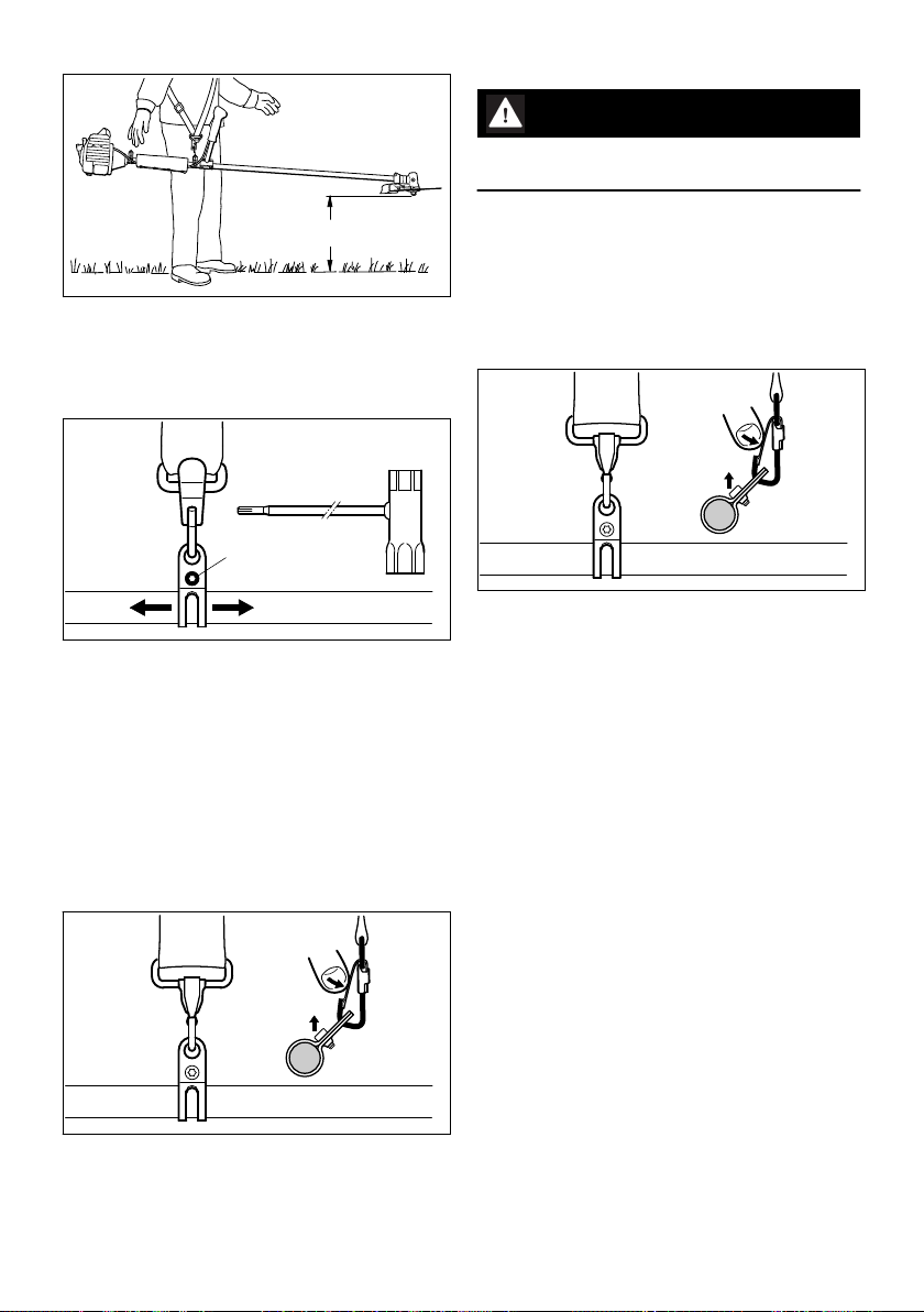
12.4 Throwing Off the Machine
WARNING
The machine must be quickly thrown off in the
event of imminent danger.
12.4.1 Method 1:
To throw off the machine, use the procedure
described under "Removing the machine".
Distance A to the saw blade should be such that
the machine with a half-full fuel tank "hovers"
horizontally above the ground.
Adjust as follows:
► Loosen the screw (3).
► Slide the carrying ring (2) along the drive tube.
► Tighten the screw moderately.
► Let the machine go until it is balanced, then
check the floating position.
When the correct floating position has been
reached:
► Tighten down the screw on the carrying ring
firmly.
12.3.5 Disconnecting machine from shoulder
strap
12.4.2 Method 2:
► Grip the handle support with your right hand
and lift the machine.
► Press down the bar on one carabiner (1) and
pull the carrying ring (2) out of the carabiner.
► Slip the strap off your left shoulder.
► Let the machine and shoulder strap fall to the
ground.
12.4.3 Both methods:
Practice removing and putting down the machine
as you would in an emergency. To avoid dam‐
age, do not throw the power tool to the ground
when practicing.
► Press down the bar on the carabiner (1) and
pull the carrying ring (2) out of the carabiner.
0458-262-0121-C 19
Page 20

3
STOP
56
4
7
002BA182 KN
1
2
START
STOP-
250BA018 KN
9
8
262BA067 KN
English 13 Starting / Stopping the Engine
13 Starting / Stopping the
Engine
13.1 Controls
13.1.1 Control handle on handlebar
► Move the slide control to START and hold it
there.
► Now release the throttle trigger, slide control
and trigger lockout in that order. This is the
starting throttle position.
► Set the choke knob (8) to:
if the engine is cold
g
for warm start – also use this position if the
e
engine has been running but is still cold.
► Press the manual fuel pump bulb (9) at least
five times – even if the bulb is filled with fuel.
13.2.1 Cranking
► If fitted: Remove the transport guard from the
cutting attachment.
1 Throttle trigger lockout
2 Throttle trigger
3 Slide control
13.1.2 Positions of slide control
4 STOP‑0 – engine off – the ignition is switched
off.
5
F – normal run position – the engine is running
or can start
6 START – ignition is switched on – the engine
can start
13.1.3 Symbol on slide control
7
h – stop symbol and arrow. To stop the
engine, push the slide control in the direction
of the arrow on the stop symbol (h) to
STOP‑0.
► Place the power tool on the ground so that it
rests on the machine support:
► Rest the gearbox end of the drive tube on a
raised support, e.g. trestle, tea bush or some‐
thing similar, to ensure that the cutting attach‐
ment can rotate freely when the engine starts.
To reduce the risk of accidents, check that the
cutting attachment is not touching the ground of
any other obstacles.
13.2 Starting
► Press down the trigger lockout lever and
squeeze the throttle trigger
► and hold them in that position.
20 0458-262-0121-C
Page 21

262BA039 KN
262BA058 KN
262BA041 KN
13 Starting / Stopping the Engine English
► Continue cranking.
13.2.2 When engine begins to fire
►
Turn the choke knob to e.
► Continue cranking until the engine runs.
13.2.3 As soon as the engine runs
► Blip the throttle trigger immediately. The slide
control moves to the normal run position F –
and the engine settles down to idle speed.
WARNING
Make sure the carburetor is correctly adjusted.
The cutting attachment must not rotate when the
engine is idling.
Your machine is now ready for operation.
13.3 Stopping the Engine
► Push the slide control in the direction of the
arrow on the stop symbol (h) to STOP‑0.
13.4 At very low outside tempera‐
► Make sure you have a firm footing, either
standing, stooping or kneeling.
► Hold the unit firmly on the ground with your left
hand and press down – do not touch the throt‐
tle trigger or lockout lever – your thumb should
be under the fan housing.
NOTICE
Do not stand or kneel on the drive tube.
► Hold the starter grip with your right hand.
► Pull the starter grip slowly until you feel it
engage and then give it a brisk strong pull.
NOTICE
Do not pull out the starter rope all the way – it
might otherwise break.
► Do not let the starter grip snap back. Guide it
slowly back into the housing so that the starter
rope can rewind properly.
As soon as the engine runs:
► Blip the throttle trigger to disengage the start‐
► Open the throttle slightly.
► Warm up the engine for a short period.
13.5 If the engine does not start
13.5.1 Choke knob
If you did not turn the choke knob to e quickly
enough after the engine began to fire, the com‐
bustion chamber is flooded.
►
► Select the starting throttle position.
► Start the engine by pulling the starter rope
If the engine still does not start
► Push the slide control in the direction of the
► Remove the spark plug – see "Spark Plug".
► Dry the spark plug.
► Open the throttle wide.
► Crank the engine several times with the starter
► Refit the spark plug – see "Spark Plug".
► Move the slide control to START.
►
► Start the engine.
tures
ing throttle position. The slide control moves to
the normal run position F – and the engine set‐
tles down to idle speed.
Turn the choke knob to e.
briskly – 10 to 20 pulls may be necessary.
arrow on the stop symbol (h) to STOP‑0.
to clear the combustion chamber.
Set the choke knob to e – even if the engine
is cold.
0458-262-0121-C 21
Page 22

681BA289 KN
681BA275 KN
1.
2.
681BA296 KN
681BA297 KN
2.
English 14 Transporting the Unit
13.5.2 Throttle Cable Adjustment
► Check adjustment of throttle cable – see chap‐
ter on "Adjusting the Throttle Cable".
13.5.3 Fuel tank run until completely dry
Recommendation: Carry out the following steps
irrespective of the engine's operating condition
before the tank was run dry.
►
Turn the choke knob to g.
► Go to section on "Starting" and re-start the
engine as described for a cold engine.
14 Transporting the Unit
14.1 Using Transport Guard
The type of transport guard depends on the
metal cutting attachment supplied with the
machine. Transport guards are available as spe‐
cial accessories.
14.1.1 Fitting the transport guard
► Fit transport guard on saw blade from below,
making sure the limit stop is properly seated in
the recess.
The transport guard can be used for 250 mm
(9.8 in) circular saw blades.
► Attach spring clip to hook on transport guard.
15 Operating Instructions
15.1 During break-in period
A factory-new machine should not be run at high
revs (full throttle off load) for the first three tank
► Unhook spring clip on transport guard and
swing it outwards.
22 0458-262-0121-C
fillings. This avoids unnecessary high loads dur‐
ing the break-in period. As all moving parts have
to bed in during the break-in period, the frictional
resistances in the engine are greater during this
period. The engine develops its maximum power
after about 5 to 15 tank fillings.
15.2 During Operation
After a long period of full throttle operation, allow
the engine to run for a short while at idle speed
Page 23

16 Cleaning the Air Filter English
so that engine heat can be dissipated by the flow
of cooling air. This protects engine-mounted
components (ignition, carburetor) from thermal
overload.
16.2 Fabric Filter with Foam Filter
15.3 After Finishing Work
Storing for a short period: Wait for the engine to
cool down. Empty the fuel tank and keep the
machine in a dry place, well away from sources
of ignition, until you need it again. For longer outof-service periods – see "Storing the Machine".
16 Cleaning the Air Filter
16.1 If there is a noticeable loss of engine power.
►
Turn the choke knob to g
16.2.1 Fabric filter
► Remove and inspect the fabric filter (3) –
replace if damaged.
► Knock out the fabric filter on a suitable surface
or blow it clear with compressed air from the
clean air side.
If filter is caked with dirt:
► Wash the fabric filter in STIHL special cleaner
or a clean, non-flammable solution (e.g. warm
soapy water) and then dry.
► Refit the clean fabric filter.
► Press in the tab (1) and remove the filter
cover (2).
► Clean away loose dirt from around the filter
and inside the filter cover.
16.2.2 Foam filter
► Remove the foam filter (4) from the filter cover
and inspect it – replace if damaged.
► Wash the foam filter in STIHL special cleaner
or a clean, non-flammable solution (e.g. warm
soapy water) and then dry.
0458-262-0121-C 23
Page 24

255BA006 KN
H
L
255BA007 KN
LA
English 17 Adjusting the Carburetor
► Coat dry foam filter uniformly with STIHL or
Oelheld air filter oil (see “Special Accesso‐
ries”) and knead it gently. Repeat the process
as necessary until oil drips from the filter.
New foam filters come impregnated with filter oil.
► Fit the foam filter in the filter cover.
► Refit the filter cover.
16.3 Paper Filter (Special Acces‐
sory)
The paper filter – see "Special Accessories" –
may be used in place of the fabric filter and foam
filter combination.
► Turn high speed screw (H) counterclockwise
as far as stop (no more than 3/4 turn).
► Turn the low speed screw (L) carefully clock‐
wise as far as stop, then turn it back 3/4 turn.
17.4 Adjusting Idle Speed
► Carry out the standard setting.
► Start and warm up the engine.
► Remove and check the paper filter (5) –
replace if dirty or damaged.
► Install the paper filter in the filter cover.
► Refit the filter cover.
17 Adjusting the Carburetor
17.1 General Information
The carburetor comes from the factory with a
standard setting.
This setting provides an optimum fuel-air mixture
under most operating conditions.
17.2 Preparations
► Shut off the engine.
► Mounting the circular saw blade.
► Check the air filter and clean or replace if nec‐
essary.
► Check that the throttle cable is properly adjus‐
ted – readjust if necessary – see chapter on
"Adjusting the Throttle Cable".
17.3 Standard setting
High speed screw (H) 3/4 turns
–
Low speed screw (L) 3/4 turns
–
24 0458-262-0121-C
17.4.1 Engine stops while idling
► Turn the idle speed screw (LA) clockwise until
the engine runs smoothly – the saw blade
must not rotate.
17.4.2 Circular saw blade rotates when
engine is idling
► Turn the idle speed screw (LA) counterclock‐
wise until the saw blade stops rotating and
then turn the screw another 1/2 to 1 full turn in
the same direction.
WARNING
If the saw blade continues to rotate when the
engine is idling, have your machine checked and
repaired by your servicing dealer.
17.4.3 Erratic idling behavior, poor accelera‐
tion (despite correction to setting of LA
screw).
Idle setting is too lean
► Turn the low speed screw (L) counterclock‐
wise, no further than stop, until the engine
runs and accelerates smoothly.
Page 25

250BA054 KN
000BA039 KN
A
1
000BA045 KN
18 Spark Plug English
17.4.4 Erratic idling behavior
Idle setting is too rich
► Turn the low speed screw (L) clockwise, no
further than stop, until the engine runs and
accelerates smoothly.
It is usually necessary to change the setting of
the idle speed screw (LA) after every correction
to the low speed screw (L).
18.2 Checking the Spark Plug
17.5 Fine Tuning for Operation at High Altitude
A slight correction of the setting may be neces‐
sary if engine does not run satisfactorily:
► Carry out the standard setting.
► Warm up the engine.
► Turn high speed screw (H) slightly clockwise
(leaner) – no further than stop.
NOTICE
After returning from high altitude, reset the car‐
buretor to the standard setting.
If the setting is too lean there is a risk of engine
damage due to insufficient lubrication and over‐
heating.
► Clean dirty spark plug.
► Check electrode gap (A) and readjust if neces‐
sary – see "Specifications".
► Rectify the problems which have caused foul‐
ing of the spark plug.
Possible causes are:
Too much oil in fuel mix.
–
Dirty air filter.
–
Unfavorable running conditions.
–
18 Spark Plug
► If the engine is down on power, difficult to start
or runs poorly at idle speed, first check the
spark plug.
► Fit a new spark plug after about 100 operating
hours – or sooner if the electrodes are badly
eroded. Install only suppressed spark plugs of
the type approved by STIHL – see "Specifica‐
tions".
18.1 Removing the Spark Plug
► Turn off the engine.
WARNING
Arcing may occur if the adapter nut (1) is loose
or missing. Working in an easily combustible or
explosive atmosphere may cause a fire or an
explosion. This can result result in serious inju‐
ries or damage to property.
► Use resistor type spark plugs with a properly
tightened adapter nut.
► Pull off the spark plug boot (1).
► Unscrew the spark plug.
0458-262-0121-C 25
Page 26

2
002BA446 KN
1
1
262BA027 KN
2
1
1
1
1
256BA075 KN
3
2
4
256BA032 KN
English 19 Engine Running Behavior
18.3 Installing the Spark Plug
► Unscrew the filler plug (1). If no grease can be
seen on the inside of the filler plug, screw the
tube (2) of STIHL gear lubricant (special
accessory) into the filler hole.
► Squeeze up to 5 g grease into the gearbox.
NOTICE
Do not completely fill the gearbox with grease.
► Remove the tube of grease (2).
► Refit the filler plug (1) and tighten it down
firmly.
21 Replacing the Starter Rope
and Rewind Spring
21.1 Removing the Fan Housing
► Screw the spark plug (2) into the cylinder and
fit the boot (1) (press it down firmly).
19 Engine Running Behavior
If engine running behavior is unsatisfactory even
though the air filter is clean and the carburetor
and throttle cable are properly adjusted, the
cause may be the muffler.
Have the muffler checked by a servicing dealer
for contamination (carbonization).
STIHL recommends that you have servicing and
repair work carried out exclusively by an author‐
ized STIHL servicing dealer.
► Take out the screws (1).
► Remove the fan housing.
21.2 Replacing the Starter Rope
20 Lubricating the Gearbox
► Remove the spring clip (2).
► Carefully remove the rope rotor with
washer (3) and pawl (4).
► Check the grease level regularly – about every
25 hours of operation.
26 0458-262-0121-C
Page 27

6
5
256BA033 KN
256BA034 KN
3
2
4
256BA032 KN
427BA016 KN
21 Replacing the Starter Rope and Rewind Spring English
WARNING
The rewind spring may pop out and uncoil during
this operation – take care to avoid the risk of
injury.
► Fit the pawl (4).
► Fit the washer (3).
► Push the spring clip (2) into position – it must
point counterclockwise as shown and engage
the pawl's peg.
21.3 Tension the rewind spring.
► Pry the cap (5) out of the grip.
► Remove the remaining rope from the rotor and
starter grip.
► Tie a simple overhand knot in the new rope
and then thread it through the top of the grip
and the rope bushing (6).
► Refit the cap in the grip.
► Thread the rope through the rotor and secure
it with a simple overhand knot.
► Coat the rope rotor bearing bore with non-res‐
inous oil.
► Slip the rotor over the starter post – turn it
back and forth to engage the anchor loop of
the rewind spring.
0458-262-0121-C 27
► Make a loop in the unwound starter rope and
use it to turn the rope rotor six full revolutions
counterclockwise.
► Hold the rope rotor steady.
► Pull out and straighten the twisted rope.
► Release the rope rotor.
► Slowly release the starter rope so that it winds
onto the rotor.
The starter grip must sit firmly in the rope bush‐
ing. If the grip droops to one side: Add one more
turn on the rope rotor to increase spring tension.
NOTICE
When the starter rope is fully extended it must
still be possible to rotate the rotor another one
and a half turns. If this is not the case, the spring
is overtensioned and could break.
► Take one turn of the rope off the rotor.
► Install the fan housing.
21.4 Replacing a Broken Rewind
Spring
► Remove the rope rotor as described in
"Replacing the Starter Rope".
Page 28

7
7
271BA053 KN
002BA432 KN
250BA072 KN
English 22 Storing the Machine
WARNING
The bits of the spring may still be under tension
and could fly apart when you remove the rope
rotor and spring housing. To reduce the risk of
injury, Wear a face shield and work gloves.
► Take out the screws (7).
► Remove the spring housing and pieces of
spring.
► Lubricate the new, ready-to-fit replacement
spring in the new spring housing with a few
drops of resin-free oil.
► Place the replacement spring with spring
housing in position – bottom plate facing up.
If the spring pops out and uncoils, refit it in the
clockwise direction, starting outside and working
inwards.
► Fit the screws.
► Refit the rope rotor as described in "Replacing
the Starter Rope".
► Tension the rewind spring.
► Install the fan housing.
23 Sharpening Metal Cutting
Blades
See cutting attachment packaging for sharpening
instructions.
24 Inspection and Mainte‐
nance by User
24.1 Changing the Fuel Pickup Body
22 Storing the Machine
If the machine is to remain out of use for approx.
3 months or more
► Drain and clean the fuel tank in a well ventila‐
ted place
► Dispose of fuel in accordance with the regula‐
tions and having regard for the environment
► Run the engine until the carburetor is dry. This
helps to prevent the carburetor diaphragms
sticking together.
► Remove, clean and inspect the cutting attach‐
ment. Treat metal cutting attachments with
protective oil.
► Thoroughly clean the machine
► Store the machine in a dry and safe place, out
of the reach of children and other unauthor‐
ized users
28 0458-262-0121-C
Change the fuel pickup body every year:
► Drain the fuel tank.
► Use a hook to pull the fuel pickup body out of
the tank and take it off the hose.
► Push the new pickup body into the hose.
► Place the pickup body in the tank.
Page 29

250BA066 KN
25 Inspections and Maintenance by Dealer English
25 Inspections and Mainte‐
nance by Dealer
25.1 Maintenance Work
STIHL recommends that you have servicing and
repair work carried out exclusively by an author‐
ized STIHL servicing dealer.
25.2 Antivibration Element
26 Maintenance and Care
The following intervals apply for normal operating
conditions. The specified intervals must be short‐
ened accordingly when working for longer than nor‐
mal or under difficult cutting conditions (extensive
dust, etc.).
A vibration-absorbing rubber element is installed
between the powerhead and the drive tube.
Have it checked if there are signs of wear or a
noticeable increase in vibration levels.
Weekly
Before starting work
Whenever tank is refilled
Monthly
If faulty
Annually
If damaged
As required
Complete machine Visual inspection (condi‐
Control handle Function test X X
Air filter, plastic fabric fil‐
ter
Air filter, paper filter Visual inspection X X
Manual fuel pump (if
present)
Fuel pickup body in fuel
tank
Fuel tank Clean X X X
0458-262-0121-C 29
tion, leaks)
Clean X
Replace any damaged
parts
Visual inspection X X
Clean X
replace X X
1)
Replace
check X
Have repaired by a spe‐
cialist dealer
check X
replace X X X
2)
At the end of work and/or daily
X X
X X
X
X
Page 30

English 27 Minimize Wear and Avoid Damage
The following intervals apply for normal operating
conditions. The specified intervals must be short‐
ened accordingly when working for longer than nor‐
mal or under difficult cutting conditions (extensive
dust, etc.).
Weekly
Before starting work
Whenever tank is refilled
Monthly
If faulty
Annually
If damaged
As required
Carburetor Check idle adjustment,
Spark plug Set electrode gap X
Intake port for cooling air Visual inspection X
Exhaust bore have cleaned after 139
All accessible screws,
nuts and bolts (not
adjusting screws)
Anti-vibration elements check X X X
Cutting attachment Visual inspection X X
Metal cutting attachment sharpen X X
Gearbox lubrication check X X X
Safety information label replace X
1)Only if there is a noticeable loss of engine power2)STIHL recommends STIHL dealers
cutting attachment must
not turn
Adjust idle speed X
Replace after every 100
hours of operation
Clean X
hours of operation, after‐
wards after every 150
hours of operation by
2)
dealer
Tighten X
Have replaced by serv‐
icing dealer
replace X
Check for secure fit X X
top up X
2)
27 Minimize Wear and Avoid
Damage
Observing the instructions in this manual helps
reduce the risk of unnecessary wear and dam‐
age to the power tool.
The power tool must be operated, maintained
and stored with the due care and attention
described in this owner's manual.
The user is responsible for all damage caused by
non-observance of the safety precautions, oper‐
At the end of work and/or daily
X X
X
ating and maintenance instructions in this man‐
ual. This includes in particular:
Alterations or modifications to the product not
–
approved by STIHL.
Using tools or accessories which are neither
–
approved or suitable for the product or are of a
poor quality.
Using the product for purposes for which it
–
was not designed.
Using the product for sports or competitive
–
events.
X
30 0458-262-0121-C
Page 31

13
14
262BA059 KN
17
18
11 11
6
7
8
9
15
1
2
3
4
5
16
#
19
20
10
12
10
28 Main Parts English
Consequential damage caused by continuing
–
to use the product with defective components.
28 Main Parts
27.1 Maintenance Work
All the operations described in the "Maintenance
Chart" must be performed on a regular basis. If
these maintenance operations cannot be per‐
formed by the owner, they should be performed
by a servicing dealer.
STIHL recommends that you have servicing and
repair work carried out exclusively by an author‐
ized STIHL servicing dealer. STIHL dealers are
regularly given the opportunity to attend training
courses and are supplied with the necessary
technical information.
If these maintenance operations are not carried
out as specified, the user assumes responsibility
for any damage that may occur. Among other
parts, this includes:
Damage to the engine due to neglect or defi‐
–
cient maintenance (e.g. air and fuel filters),
incorrect carburetor adjustment or inadequate
cleaning of cooling air inlets (intake ports, cyl‐
inder fins).
Corrosion and other consequential damage
–
resulting from improper storage.
Damage to the machine resulting from the use
–
of poor quality replacement parts.
27.2 Parts Subject to Wear and Tear
Some parts of the power tool are subject to nor‐
mal wear and tear even during regular operation
in accordance with instructions and, depending
on the type and duration of use, have to be
replaced in good time. Among other parts, this
includes:
Cutting attachments (all types)
–
Mounting hardware for cutting attachments
–
(rider plate, nut, etc.)
Deflectors for cutting attachments
–
Clutch
–
Filters (air, fuel)
–
Rewind starter
–
Spark plug
–
Antivibration elements
–
1 Tank cap
2 Carburetor adjusting screws
3 Starter grip
4 Spark plug boot
5 Muffler
6 Bike handle (handlebar)
7 Throttle trigger
8 Slide control
9 Throttle trigger lockout
10 Carrying ring
11 Throttle cable retainer
12 Padding
13 Manual fuel pump
14 Choke knob
15 Air filter cover
16 Fuel tank
17 Machine support
18 Handle support
19 Metal cutting attachment
20 Limit stop
# Serial number
29 Specifications
29.1 Engine
STIHL single cylinder two-stroke engine
Displacement:
Bore: 40 mm
Stroke: 32 mm
40.2 cc
0458-262-0121-C 31
Page 32

000BA073 KN
English 30 Maintenance and Repairs
Engine power to ISO 8893: 1.6 kW (2.2 bhp) at
Idle speed: 2,800 rpm
Cut-off speed (rated): 10,500 rpm
Max. output shaft speed
(cutting attachment):
9,000 rpm
9,270 rpm
29.2 Ignition system
Electronic magneto ignition
Spark plug (resistor type): NGK BPMR 7 A,
Electrode gap: 0.5 mm
Bosch WSR 6 F
29.3 Fuel System
All position diaphragm carburetor with integral
fuel pump
Fuel tank capacity:
640 cc (0.64 l)
29.4 Weight
dry, without cutting attachment and
limit stop:
6.1 kg
29.5 Overall length
without cutting attachment 1545 mm
29.6 Exhaust Emissions
The CO2value measured in the EU type approval
procedure is specified at www.stihl.com/co2.
The measured CO2value was determined on a
representative engine in accordance with a
standardized test procedure under laboratory
conditions and does not represent either an
explicit or implied guarantee of the performance
of a specific engine.
The applicable exhaust emission requirements
are fulfilled by the intended usage and mainte‐
nance described in this instruction manual. The
type approval expires if the engine is modified in
any way.
When repairing the machine, only use replace‐
ment parts which have been approved by STIHL
for this power tool or are technically identical.
Only use high-quality replacement parts in order
to avoid the risk of accidents and damage to the
machine.
STIHL recommends the use of original STIHL
replacement parts.
Original STIHL parts can be identified by the
STIHL part number, the { logo and the
STIHL parts symbol K (the symbol may appear
alone on small parts).
31 Disposal
Observe all country-specific waste disposal rules
and regulations.
STIHL products must not be thrown in the gar‐
bage can. Take the product, accessories and
packaging to an approved disposal site for envi‐
ronment-friendly recycling.
Contact your STIHL servicing dealer for the lat‐
est information on waste disposal.
30 Maintenance and Repairs
Users of this machine may only carry out the
maintenance and service work described in this
user manual. All other repairs must be carried
out by a servicing dealer.
STIHL recommends that you have servicing and
repair work carried out exclusively by an author‐
ized STIHL servicing dealer. STIHL dealers are
regularly given the opportunity to attend training
courses and are supplied with the necessary
technical information.
32 0458-262-0121-C
Page 33

31 Disposal English
0458-262-0121-C 33
Page 34

English 31 Disposal
34 0458-262-0121-C
Page 35

31 Disposal English
0458-262-0121-C 35
Page 36

www.stihl.com
*04582620121C*
0458-262-0121-C
*04582620121C*
0458-262-0121-C
 Loading...