

STIHL FS 561 C-M
Instruction Manual
Notice d’emploi

G Instruction Manual
1 - 50
F Notice d’emploi
51 - 106

Contents
English
Guide to Using this Manual 2
Safety Precautions and Working
Techniques 3
Approved Combinations of Cutting
Attachment, Deflector, Limit Stop
and Harness 13
Mounting the Bike Handle 15
Adjusting the Throttle Cable 18
Mounting the Deflector 19
Original Instruction ManualPrinted on chlorine-free paper
Mounting the Cutting Attachment 21
Fuel 27
Fueling 28
Fitting the Full Harness 28
Balancing the Machine 29
Starting / Stopping the Engine 30
Transporting the Unit 32
Operating Instructions 34
Air filter 34
Engine Management 35
M-Tronic 35
Winter Operation 36
Spark Plug 38
Printing inks contain vegetable oils, paper can be recycled.
Engine Running Behavior 39
Lubricating the Gearbox 39
Storing the Machine 39
Sharpening Metal Cutting Blades 40
Maintaining the Mowing Head 40
Inspection and Maintenance by
User 41
Inspections and Maintenance by
Dealer 42
Maintenance and Care 43
Main Parts 45
Specifications 47
Maintenance and Repairs 48
Disposal 48
STIHL Limited Emission Control
Warranty Statement 49
Allow only persons who fully understand
this manual to operate your clearing
saw.
To receive maximum performance and
satisfaction from your STIHL clearing
saw, it is important that you read,
understand and follow the safety
precautions and the operating and
maintenance instructions in chapter
"Safety Precautions and Working
Techniques" before using your clearing
saw. For further information you can go
to www.stihlusa.com.
Contact your STIHL dealer or the STIHL
distributor for your area if you do not
understand any of the instructions in this
manual.
WARNING
Because a clearing saw is a high-speed
cutting tool some special safety
precautions must be observed to reduce
the risk of personal injury. Careless or
improper use may cause serious or even
fatal injury.
Make sure your unit is equipped with the
proper deflector or limit stop, handle and
harness for the type of cutting
attachment being used. Always wear
proper eye protection.
© ANDREAS STIHL AG & Co. KG, 2022
0458-856-8221-A. VA4.B22.
0000009340_004_GB
FS 561 C-M
This instruction manual is protected by copyright. All rights reserved, especially the rights to reproduce, translate and process
with electronic systems.
1
English
Guide to Using this Manual
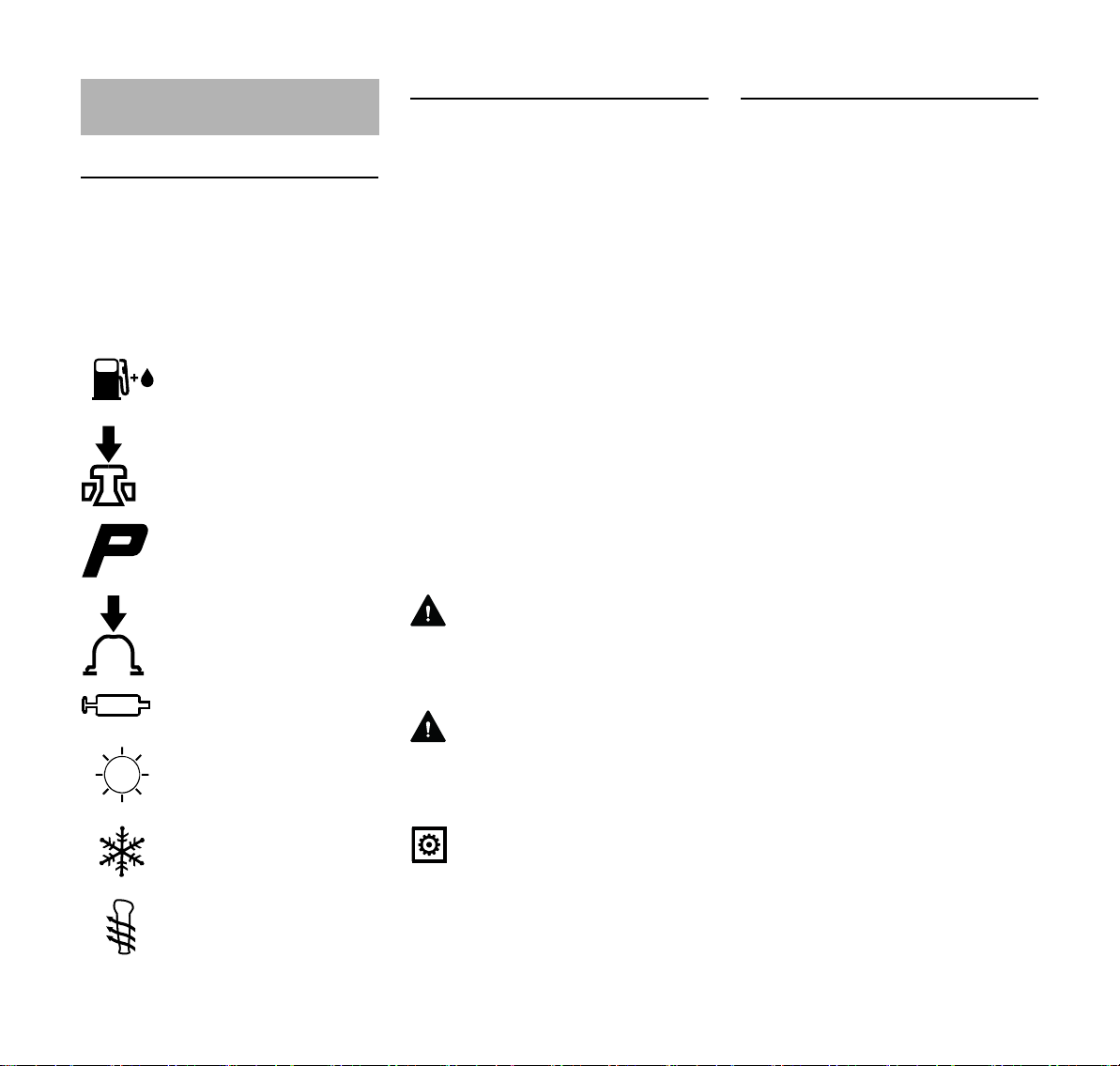
Pictograms
The meanings of the pictograms
attached to or embossed on the
machine are explained in this manual.
Depending on the model concerned, the
following pictograms may be on your
machine.
Fuel tank for gasoline
and engine oil mixture
Press to operate decom
pression valve
Manual fuel pump
Press to operate manual
fuel pump
Filler hole for gear
lubricant
Air intake summer mode
Air intake winter mode
Handle heating
Symbols in Text
Many operating and safety instructions
are supported by illustrations.
The individual steps or procedures
described in the manual may be shown
in different ways:
N A bullet indicates a step or
procedure.
A description of a step or procedure that
refers directly to an illustration may
contain item numbers that appear in the
illustration. For example:
N Remove the screw (1)
N Pull the spark arresting screen (2)
-
upwards out of the muffler
In addition to the operating instructions,
this manual may contain paragraphs
that require your special attention. Such
paragraphs are indicated with the
symbols and signal words described
below:
DANGER
Indicates a hazardous situation that, if
not avoided, will result in death or
serious injury.
WARNING
Indicates a hazardous situation that, if
not avoided, could result in death or
serious injury.
NOTICE
Indicates a risk of property damage,
including damage to the machine or its
individual components.
Engineering Improvements
STIHL’s philosophy is to continually
improve all of its products. As a result,
engineering changes and improvements
are made from time to time. Therefore,
some changes, modifications and
improvements may not be covered in
this manual. If the operating
characteristics or the appearance of
your machine differs from those
described in this manual, please contact
your STIHL dealer or the STIHL
distributor for your area for assistance.
2
FS 561 C-M

English
Safety Precautions and
Working Techniques
Because the machine is a
high-speed fast-cutting
power tool, special safety
precautions must be
observed to reduce the
risk of personal injury.
It is important you read
and understand the User
Manual before commis
sioning and keep it in a
safe place for future ref
erence. Non-compliance
with the User Manual
may cause serious or
even fatal injury.
Observe all applicable local safety
regulations, e.g. by trade organizations,
social insurance institutions, labor safety
authorities etc.
If you have never used a power tool
before: Have your dealer or other
experienced user show you how to
operate your machine – or attend a
special course to learn how to operate it.
Minors should never be allowed to use
the machine – except for apprentices
over the age of 16 when working under
supervision.
Children, animals and bystanders must
remain at a distance.
When not using the machine, it must be
laid down in such a way that it does not
endanger anyone. Ensure that the
machine cannot be used without
authorization.
-
-
The user is responsible for accidents or
risks involving third parties or their
property.
Do not lend or rent your power tool
without the User Manual. Be sure that
anyone using it understands the
information contained in this manual.
The use of machines that emit noise
may be limited to certain hours of the
day as specified by national and/or
regional or local regulations.
Anyone operating the machine must be
well rested, in good physical health and
in good mental condition.
If you have any condition that might be
aggravated by strenuous work, check
with your doctor before operating a
machine.
If you have a pacemaker: The ignition
system of your machine produces an
electromagnetic field of very low
intensity. This field may interfere with
some pacemakers. STIHL recommends
that persons with pacemakers consult
their physician and the pacemaker
manufacturer to reduce any health risk.
Anyone who has consumed alcohol or
drugs or medicines affecting their ability
to react must not operate a power tool.
Depending on the cutting attachment
fitted, use your power tool only for
cutting grass, wild growth, shrubs,
scrub, bushes, small diameter trees and
similar materials.
The machine must not be used for any
other purposes – risk of accidents!
Only use cutting attachments and
accessories that are explicitly approved
for this power tool model by STIHL or
are technically identical. If you have any
questions in this respect, consult your
dealer. Use only high quality parts and
accessories. in order to avoid the risk of
accidents and damage to the machine.
STIHL recommends the use of original
STIHL tools and accessories. They are
specifically designed to match the
product and meet your performance
requirements.
Never attempt to modify your power tool
in any way since this may increase the
risk of personal injury. STIHL excludes
all liability for personal injury and
damage to property caused while using
unauthorized attachments.
Do not use a high-pressure washer to
clean the power tool. The solid jet of
water may damage parts of the unit.
The guard provided with your machine
may not protect the operator from all
foreign objects (gravel, glass, wire etc.)
ejected by the revolving cutting
attachment. Ejected objects may also
ricochet and strike the operator.
Clothing and equipment
Wear proper protective clothing and
equipment.
Clothing must be sturdy
but allow complete free
dom of movement. Wear
close-fitting clothes such
as a boiler suit, not a
loose jacket.
Do not wear clothing which could
become trapped in wood, brush or
moving parts of the machine. Do not
-
FS 561 C-M
3
English
002BA479 KN
wear a scarf, necktie or jewelry. Tie up
and confine long hair above your
shoulders.
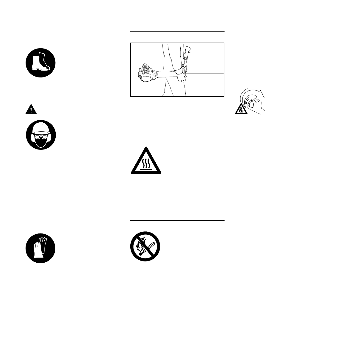
Wear safety boots with
steel toe caps and nonslip soles.
Sturdy shoes with non-slip shoes are
permissible only when using mowing
heads.
WARNING
To reduce the risk of eye
injuries, wear close-fit
-
ting safety glasses in
accordance with Euro
-
pean Standard EN 166.
Make sure the safety
glasses are a snug fit.
Wear face protection and make sure it is
a good fit. Face protection alone is not
sufficient to protect the eyes.
Wear "personal" sound protection, e.g.
ear defenders.
Wear a safety hard hat for thinning
operations, when working in high scrub
and where there is a danger of head
injuries from falling objects.
Wear sturdy protective
gloves made of a resist
-
ant material (e. g.
leather).
Transporting the machine
Always stop the engine.
Carry the machine hanging on the
harness or by the shaft so that it is
balanced. Fit transport guard on metal
cutting attachments to avoid the risk of
injury from blade contact
Avoid touching hot parts
of the machine and gear
box – risk of burns!
By vehicle: When transporting in a
vehicle, properly secure your machine to
prevent turnover, damage and fuel
spillage.
Refueling
Gasoline is highly flam
-
mable – keep away from
fire or flame – do not spill
any fuel – no smoking.
Open the fuel cap carefully to allow any
pressure build-up in the tank to release
slowly and avoid fuel spillage.
Only refuel the machine in a well
ventilated place. If fuel has been spilled,
immediately clean the machine – do not
allow your clothes to be splashed with
fuel. If that happens, change your
clothes at once.
After fueling, tighten
down the screw-type fuel
cap as securely as
possible.
This helps reduce the risk of engine
vibrations causing an incorrectly
tightened fuel cap to loosen or come off
and spill fuel.
Check for leaks. Do not start the engine
-
if there is a fuel leak – serious or fatal
burns could result!
STIHL can supply a comprehensive
range of personal protective equipment.
4
Always shut off the engine before
refueling.
Do not fuel a hot engine – fuel may spill
and cause a fire.
FS 561 C-M

English
002BA480 KN
Before starting
Check that your power tool is properly
assembled and in good condition – refer
to appropriate chapters in the User
Manual.
– Check the fuel system for leaks,
especially the visible parts, e. g.,
fuel cap, hose connections, manual
fuel pump (only in machines with a
manual fuel pump). In case of
leakage and damage, do not start
the engine – risk of fire! Have the
machine serviced by a dealer
before using it
– Use only an approved combination
of cutting attachment, deflector,
handle and harness. All parts must
be assembled properly and
securely
– The stop switch must be easy to
push
– Check the choke lever, throttle
trigger and throttle trigger lockout
for smooth action - throttle trigger
must return automatically to idle
position. The choke lever must
spring back from the } position to
the run position F when the throttle
trigger lockout and throttle trigger
are squeezed.
– Check that the spark plug boot is
secure – a loose boot may cause
sparking that could ignite
combustible fumes and cause a fire!
– Cutting attachment or
interchangeable attachment:
correctly fitted, secure and in
perfect condition
– Safety devices (e. g., deflector for
cutting attachments, rider plate) for
damage and/or wear. Always
replace damaged parts. Do not use
the machine with a damaged
deflector or worn rider plate (if the
writing and arrows are no longer
discernible)
– Never attempt to modify the controls
or safety devices
– Keep the handles dry and clean –
free from oil and dirt – this is
important for safe control of the
machine
– Adjust the harness and handle(s) to
suit your height and reach Note the
information in the chapters "Fitting
the Harness" and "Balancing the
Machine".
To reduce the risk of personal injury, do
not operate your power tool if it is
damaged or not properly assembled!
To prepare for emergencies when using
a harness: Practice setting down the
machine quickly. To avoid damage, do
not throw the unit to the ground when
practicing.
Starting the engine
Start the engine at least 3 meters from
the fueling spot, outdoors only.
Place the unit on firm ground in an open
area. Make sure you have good balance
and secure footing. Hold the unit
securely. The cutting attachment must
be clear of the ground and all other
obstructions because it may begin to run
when the engine starts.
This is a one-person machine – ensure
that there is no-one within 15 meters of
the machine, not even when starting the
power tool! Risk of injury due to ejected
objects!
Avoid contact with the
cutting attachment – risk
of injury!
Do not drop-start the
power tool – start the
engine as described in
the User Manual. The
cutting attachment runs
on for a short while after
releasing the throttle trig
ger – coasting effect!
Keep easily combustible materials
(e. g., wood chips, bark, dry grass, fuel)
away from hot exhaust gases and hot
muffler surfaces – risk of fire!
Holding and guiding the machine
Always hold the unit firmly with both
hands on the handles.
Make sure you always have good
balance and secure footing.
Right hand on control handle, left hand
on grip on handlebar.
-
FS 561 C-M
5

English
15m (50ft)
While working
Make sure you always have good
balance and secure footing.
In the event of imminent danger or in an
emergency, push the stop switch to stop
the engine.
Within a wide area around the
workplace, there is a risk of accident by
ejected objects, therefore ensure that
there is no-one within a 15 m radius of
the machine. This distance must also be
maintained in relation to objects
(vehicles, window panes) – risk of
property damage! Even at a distance
over 15 m, danger cannot be ruled out.
Check that the engine is properly idling
so that the cutting tool will not continue
rotating after you release the throttle
trigger. If the cutting attachment still
rotates at idle speed, have your dealer
make proper adjustments or repairs.
STIHL recommends you have this work
done by a STIHL servicing dealer.
Take special care in slippery conditions
– damp, snow, ice, on slopes or uneven
ground.
Watch out for obstacles: tree stumps,
roots – risk of tripping or stumbling!
Only work while standing on the ground,
never on a ladder, work platform or other
unstable surface.
Be particularly alert and cautious when
wearing hearing protection because
your ability to hear warnings (shouts,
alarms, etc.) is restricted.
Take breaks when you start getting tired
or feeling fatigue – risk of accidents!
Work calmly and carefully – in daylight
conditions and only when visibility is
good. Proceed with caution, do not put
others in danger.
As soon as the engine is
running, the power
machine generates toxic
exhaust gas. These
gases may be odorless
and invisible and may
contain unburned hydro
carbons and benzene.
Never run the engine
indoors or in poorly venti
lated locations, even if
your model is equipped
with a catalytic converter.
To reduce the risk of serious or fatal
injury from breathing toxic fumes,
ensure proper ventilation when working
in trenches, hollows or other confined
locations.
Stop work immediately if you start
suffering from nausea, headaches,
impaired vision (e.g. your field of vision
gets smaller), impaired hearing,
dizziness, or impaired concentration –
these symptoms may possibly be the
result of too-high exhaust gas
concentration – Risk of accidents!
Operate your power tool so that it
produces a minimum of noise and
emissions – do not run the engine
unnecessarily, accelerate the engine
only when working.
To reduce the risk of fire, do not smoke
while operating or standing near your
power tool. Combustible fuel vapor may
escape from the fuel system.
Dust, fumes and smoke produced while
working may be hazardous to your
health. Wear respiratory protection in
case of heavy dust or smoke emission.
If your power tool is subjected to
unusually high loads for which it was not
designed (e.g. heavy impact or a fall),
always check that it is in good condition
before continuing work – see also
"Before Starting".
Check in particular that the fuel system
has no leaks and the safety equipment is
-
fully operative. Never use a power tool
that is no longer safe to operate. In case
of doubt, contact a dealer.
-
To reduce the risk
of injuryfrom
thrown objects,
never operate the
unit without the
proper deflector for
the type of cutting
attachment being
used.
Check the work site –
rocks, metal objects etc.
may be caught up and
ejected – possibly over a
distance of 15 m – risk of
injury! – They can also
damage the cutting
attachment and other
property (e. g. parking
vehicles, windows).
Be particularly careful when working on
difficult, densely grown terrain.
6
FS 561 C-M

English
When mowing in high shrubbery, under
shrubbery and hedges: Hold the cutting
tool at a working height of at least 15 cm
– avoid risks to animals.
Always shut off the engine before
leaving the unit unattended.
Examine the cutting attachment
periodically at short intervals and as
soon as you note any noticeable
changes:
– Stop the engine, hold the machine
securely, allow the cutting
attachment to come to a stop
– Check condition and secure fitting;
watch out for cracks
– Ensure that the cutting blades are
sharp
– Replace damaged or blunt cutting
attachments immediately, even in
the event of minor hairline cracks
Clean grass and plant residue off the
cutting attachment mounting at regular
intervals – remove any build up of
material from the cutting attachment and
deflector.
To reduce the risk of injury, shut off the
engine before replacing the cutting
attachment.
The gearbox gets hot
during operation. Never
touch the gearbox – risk
of burns!
Do not continue using or attempt to
repair damaged or cracked cutting
attachments by welding, straightening or
modifying the shape (out of balance).
Particles or pieces may come off and hit
the operator or a bystander at a high
speed – risk of most severe injuries!
If a rotating cutting attachment touches a
rock or another hard object, sparks may
be generated which may possibly ignite
combustible materials. Also dried-out
plants and brushwood are combustible,
above all in hot and dry weather. If there
is a risk of fire, do not use cutting
attachments in the vicinity of
combustible materials, dried-out plants
or brushwood. It is mandatory that you
ask the responsible forestry office about
the current fire hazard.
Using mowing heads
Use only the deflector with properly
mounted line limiting blade to ensure the
mowing lines are automatically trimmed
to the approved length.
Always switch off the engine to adjust
the mowing line for manually adjustable
mowing heads – risk of injury!
Misuse with mowing lines that are too
long reduces the working speed of the
engine. The constant slipping of the
clutch causes overheating and damage
to important components (e. g. clutch,
plastic housing parts) – e. g. due to the
cutting attachment rotating during idling
– risk of injury!
When using metal cutting attachments
STIHL recommends the use of original
STIHL metal cutting attachments. These
have been optimized for the machine
and the user’s requirements.
Metal cutting attachments rotate very
fast, generating forces acting on the
attachments and on the cuttings.
Metal cutting attachments must be
sharpened in regular intervals in
accordance with the instructions.
Unevenly sharpened metal cutting
attachments generate an imbalance
which may cause extreme loads on the
machine – risk of breakage!
Dull or improperly sharpened cutting
edges can put a higher load on the
cutting attachment and increase the risk
of injuryfrom cracked or broken parts.
After each contact of the metal cutting
attachment with hard objects (e.g.
stones, rocks, metal parts), check it for
damage (e.g. tears and deformation).
Burrs and other visible material
accumulations must be removed since
they may come loose at any time while
the machine is running and then be
ejected – risk of injury!
To reduce the above-named risks
involved in operating a metal cutting
attachment, ensure that the diameter of
your metal cutting attachment is not too
big. Also, the attachment must not be
too heavy. It must be made of highquality materials and have a suitable
geometry (shape, thickness).
A metal cutting attachment not made by
STIHL must not have a different weight,
thickness, shape and a larger diameter
than the largest STIHL metal cutting
attachment approved for this metal
cutting attachment – risk of injury!
FS 561 C-M
7

English
Vibrations
Prolonged use of the power tool may
result in vibration-induced circulation
problems in the hands (whitefinger
disease).
No general recommendation can be
given for the length of usage because it
depends on several factors.
The period of usage is prolonged by:
– Hand protection (wearing warm
gloves)
– Work breaks
The period of usage is shortened by:
– Any personal tendency to suffer
from poor circulation (symptoms:
frequently cold fingers, tingling
sensations).
– Low outside temperatures.
– The force with which the handles
are held (a tight grip restricts
circulation).
Continual and regular users should
monitor closely the condition of their
hands and fingers. If any of the above
symptoms appear (e.g. tingling
sensation in fingers), seek medical
advice.
Maintenance and Repairs
Service the machine regularly. Do not
attempt any maintenance or repair work
not described in the instruction manual.
Have all other work performed by a
servicing dealer.
STIHL recommends that you have
servicing and repair work carried out
exclusively by an authorized STIHL
servicing dealer. STIHL dealers are
regularly given the opportunity to attend
training courses and are supplied with
the necessary technical information.
Only use high-quality replacement parts
in order to avoid the risk of accidents
and damage to the machine. If you have
any questions in this respect, consult a
servicing dealer.
STIHL recommends the use of original
STIHL replacement parts. They are
specifically designed to match your
model and meet your performance
requirements.
To reduce the risk of injury from
unintentional engine startup, always
shut off the engine and disconnect the
spark plug boot before performing any
repairs, maintenance or cleaning work. –
Exception: Carburetor and idle speed
adjustments.
Do not turn the engine over on the
starter with the spark plug boot or spark
plug removed since there is otherwise a
risk of fire from uncontained sparking.
To reduce the risk of fire, do not service
or store your machine near open flames.
Check the fuel filler cap for leaks at
regular intervals.
Use only a spark plug of the type
approved by STIHL and make sure it is
in good condition – see "Specifications".
Inspect the ignition lead (insulation in
good condition, secure connection).
Check the condition of the muffler.
To reduce the risk of fire and damage to
hearing, do not operate your machine if
the muffler is damaged or missing. –
Do not touch a hot muffler since burn
injury will result.
Vibration behavior is influenced by the
condition of the AV elements – check the
AV elements at regular intervals.
Maintenance, replacement, or repair of
the emission control devices and
systems may be performed by any
nonroad engine repair establishment or
individual. However, if you make a
warranty claim for a component which
has not been serviced or maintained
properly, STIHL may deny coverage.
For any maintenance please refer to the
maintenance chart and to the warranty
statement near the end of the instruction
manual.
Symbols on Deflectors
An arrow on the deflector shows the
correct direction of rotation of the cutting
attachments.
Some of the following symbols are
applied to the outside of the deflector to
indicate the approved combination of
cutting attachment and deflector.
Deflector may be used
with mowing heads.
8
FS 561 C-M
English
002BA397 KN
000BA015 KN
Deflector may be used
with grass cutting blades.
Deflector may be used
with brush knives.
Deflector may be used
with shredder blades.
Deflector must not be
used with mowing heads.
Deflector must not be
used with grass cutting
blades.
Deflector must not be
used with brush knives.
Deflector must not be
used with shredder
blades.
Deflector must not be
used with circular saw
blades.
Harness
The harness is included with the
machine or available as a special
accessory.
N Use the harness.
N With the engine running, attach the
machine to the harness.
All cutting attachments must be used in
combination with a full harness with a
quick-release system.
Mowing Head with Nylon Line
Nylon line achieves a soft cut for edging
and trimming around trees, fence posts,
etc. – less risk of damaging tree bark.
The mowing head comes with an
instruction leaflet. Refill the mowing
head with nylon line as described in the
instruction leaflet.
WARNING
To reduce the risk of serious injury,
never use wire or metal-reinforced line in
place of the nylon line.
STIHL DuroCut
FS 561 C-M
Check the wear limit marks!
9

English
681BA209 KN
002BA396 KN
002BA135 KN
If one of the wear limit marks imbedded
in the baseplate of the DuroCut
(exclamation marks) becomes visible,
do not continue using the mowing head
since it may otherwise be damaged.
Replace the worn baseplate.
The mowing head comes with
instruction leaflets. Equip the mowing
head only with nylon line as described in
the instruction leaflets.
WARNING
Never use wire in place of the nylon
mowing line – risk of injury.
STIHL Polycut Mowing Head with
Polymer Blades
For mowing unobstructed edges of
meadows (without posts, fences, trees
or similar obstacles).
Check the wear limit marks!
If one of the wear limit marks on the
PolyCut mowing head is worn through
(arrow): Do not continue using the
mowing head. Install a new one. There
is otherwise a risk of injury from thrown
parts of the head.
It is important to follow the maintenance
instructions for the PolyCut mowing
head.
The PolyCut can also be equipped with
mowing line in place of the polymer
blades.
The mowing head comes with
instruction leaflets. Equip the mowing
head with polymers blades or nylon line
as described in the instruction leaflets.
WARNING
Never use wire in place of the nylon
mowing line – risk of injury.
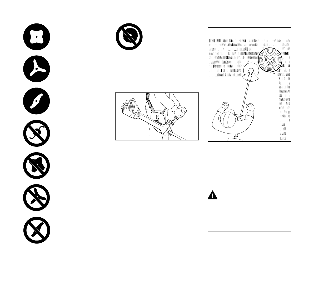
Risk of Kickout (Blade Thrust) with Metal
Cutting Attachments
WARNING
When using metal cut
-
ting attachments there is
a risk of kickout when the
rotating blade comes into
contact with a solid object
such as a tree trunk,
branch, tree stump, rock
or similar. The machine is
thrown to the right or to
the rear – opposite to the
attachment's direction of
rotation.
The risk of kickout is greatest when the
black area of the rotating cutting
attachment comes into contact with a
solid object.
10
FS 561 C-M

English
000BA020 KN
002BA355 KN
002BA509 KN
002BA210 KN
Grass Cutting Blade
Use for grass and weeds only – sweep
the brushcutter in an arc like a scythe.
WARNING
Improper use may damage the grass
cutting blade – risk of injury from thrown
parts.
Resharpen the grass cutting blade
according to instructions when it has
dulled noticeably.
Brush Knife
For cutting matted grass, wild growth
and scrub and thinning young stands
with a stem diameter of no more than
2 cm – do not cut thicker stems – risk of
accidents.
Use the brushcutter like a scythe (sweep
it to the right and left) at ground level
when cutting grass and thinning young
stands.
To cut wild growth and scrub, lower the
brush knife down onto the growth to
achieve a shredding effect – always
keep the cutting attachment below hip
level during this process.
Exercise extreme caution when using
this method of cutting. The higher the
cutting attachment is off the ground, the
greater the risk of injury from cuttings
being thrown sideways.
Warning! Improper use of a brush knife
may cause it to crack, chip or shatter –
risk of injury from thrown parts.
To reduce the risk of injury it is essential
to take the following precautions:
– Avoid contact with stones, rocks,
pieces of metal and other solid
foreign objects.
– Never cut wood or shrubs with a
stem diameter of more than 2 cm –
use a circular saw blade for such
work.
– Inspect the brush knife at regular
short intervals for signs of damage.
Do not continue working with a
damaged brush knife.
– Resharpen the brush knife regularly
and whenever it has dulled
noticeably, and have it balanced if
necessary (STIHL recommends a
STIHL servicing dealer).
Shredder Blade
Suitable for thinning and shredding
tough, matted grass and scrub.
To cut wild growth and scrub, lower the
shredder blade down onto the growth to
achieve a shredding effect – always
keep the cutting attachment below hip
level during this process.
FS 561 C-M
11

English
002BA449 KN
Exercise extreme caution when using
this method of cutting. The higher the
cutting attachment is off the ground, the
greater the risk of injury from cuttings
being thrown sideways.
Warning! Improper use may damage the
shredder blade – risk of injury from
thrown parts.
To reduce the risk of injury it is essential
to take the following precautions:
– Avoid contact with stones, rocks,
pieces of metal and other solid
foreign objects.
– Never cut wood or shrubs with a
stem diameter of more than 2 cm –
use a circular saw blade for such
work.
– Inspect the shredder blade at
regular short intervals for signs of
damage. Do not continue working
with a damaged shredder blade.
– Resharpen the shredder blade
regularly and whenever it has dulled
noticeably, and have it balanced if
necessary (STIHL recommends a
STIHL servicing dealer).
Circular Saw Blade
Suitable for cutting shrubs and trees with
a maximum stem diameter of 7 cm.
Before starting the cut, accelerate the
engine up to full throttle. Perform cut
with uniform pressure.
Use circular saw blades only with a
matching limit stop of the correct
diameter.
WARNING
To reduce the risk of blade damage,
avoid contact with stones and the
ground. Resharpen the blade properly in
good time – dull teeth may result in the
blade cracking and shattering and
causing serious injury.
When felling, maintain a distance of at
least two tree lengths from the next
felling site.
Risk of kickout
The risk of kickout is highest in the black
area of the blade: Do not use this area of
the circular saw blade for cutting.
There is also a risk of kickout when
using the lighter shaded areas of the
blade: These areas of the blade should
only be used by experienced operators
with specialized training.
STIHL recommends that you use the
non-shaded area of the circular saw
blade. Always start the cut with this area
of the blade.
12
FS 561 C-M
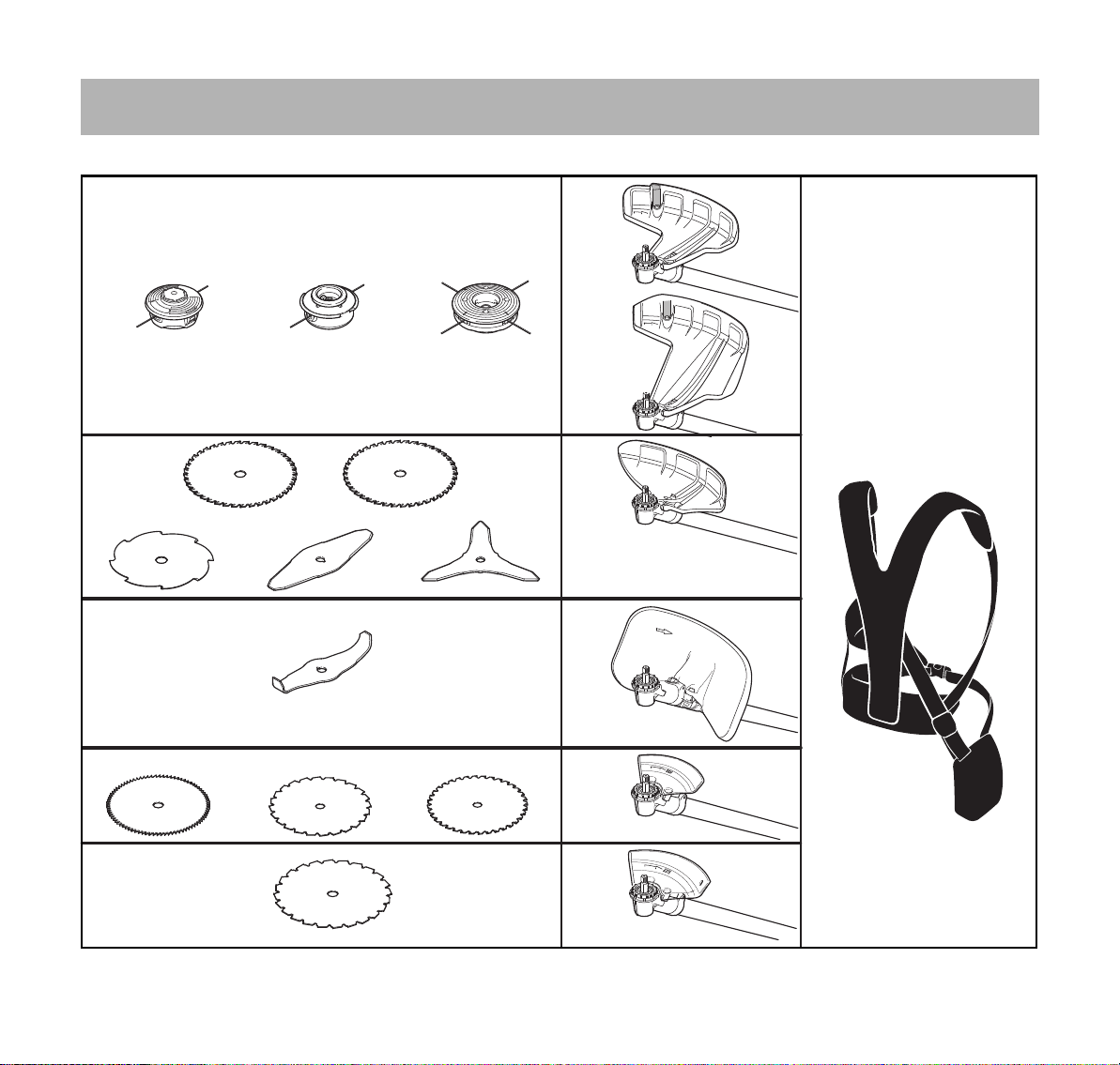
Approved Combinations of Cutting Attachment, Deflector, Limit Stop and Harness
9
10
11
12
18
17
16
14
5
8
0000098045_001
7
6
20
1
3
2
4
15
13
19
Cutting attachment Deflector, limit stop Carrying strap
English
FS 561 C-M
13

English
Permissible combinations
Choose the correct combination from
the table depending on the cutting tool!
WARNING
For safety reasons only the cutting
attachments and deflectors and/or limit
stops within one line of the table may be
combined with one another. No other
combinations are permitted because of
the risk of accidents!
Cutting attachments
Mowing heads
1 STIHL AutoCut 56-2
2 STIHL TrimCut C 52-2
3 STIHL DuroCut 40-4
Metal cutting tools
4 Grass cutting blade 250-32 Spezial
(Ø 250 mm)
5 Grass cutting blade 250-40 Spezial
(Ø 250 mm)
6 Grass cutting blade 255-8
(Ø 255 mm)
7 Brush knife 305-2 Spezial
(Ø 305 mm)
8 Brush knife, 350-3
(Ø 350 mm)
9 Shredder blade 320-2
(Ø 320 mm)
10 Circular saw blade 225 scratcher
tooth
(Ø 225 mm)
11 Circular saw blade 225 chisel tooth
(Ø 225 mm)
12 Carbide tipped circular saw blade
225
(Ø 225 mm)
13 Circular saw blade 250, chisel tooth
(250 mm dia.)
WARNING
Non-metal grass cutting blades, brush
knives, shredder blades and circular
saw blades are not permitted.
Deflectors, limit stop
14 Deflector for mowing heads
(Ø 480 mm)
15 Deflector for mowing heads
(Ø 560 mm)
16 Guard for metal cutting tools,
items 4 to 8
17 Guard for shredder blades
18 Limit stop for circular saw blades
(Ø 225 mm)
19 Limit stop for circular saw blades
(Ø 250 mm)
Carrying strap
20 Full harness must be used
WARNING
Based on the cutting attachment being
used:
Choose the proper deflector in order to
reduce the risk of injury from thrown
objects and contact with the cutting
attachment.
Make sure your unit is equipped with the
proper handle and harness in order to
reduce the risk of injury from loss of
control and contact with the cutting
attachment.
Use grass cutting metal blades, brush
knifes and circular saw blades on this
unit only if equipped with a bike handle.
Do not use rigid polymer blades on this
unit.
14
FS 561 C-M

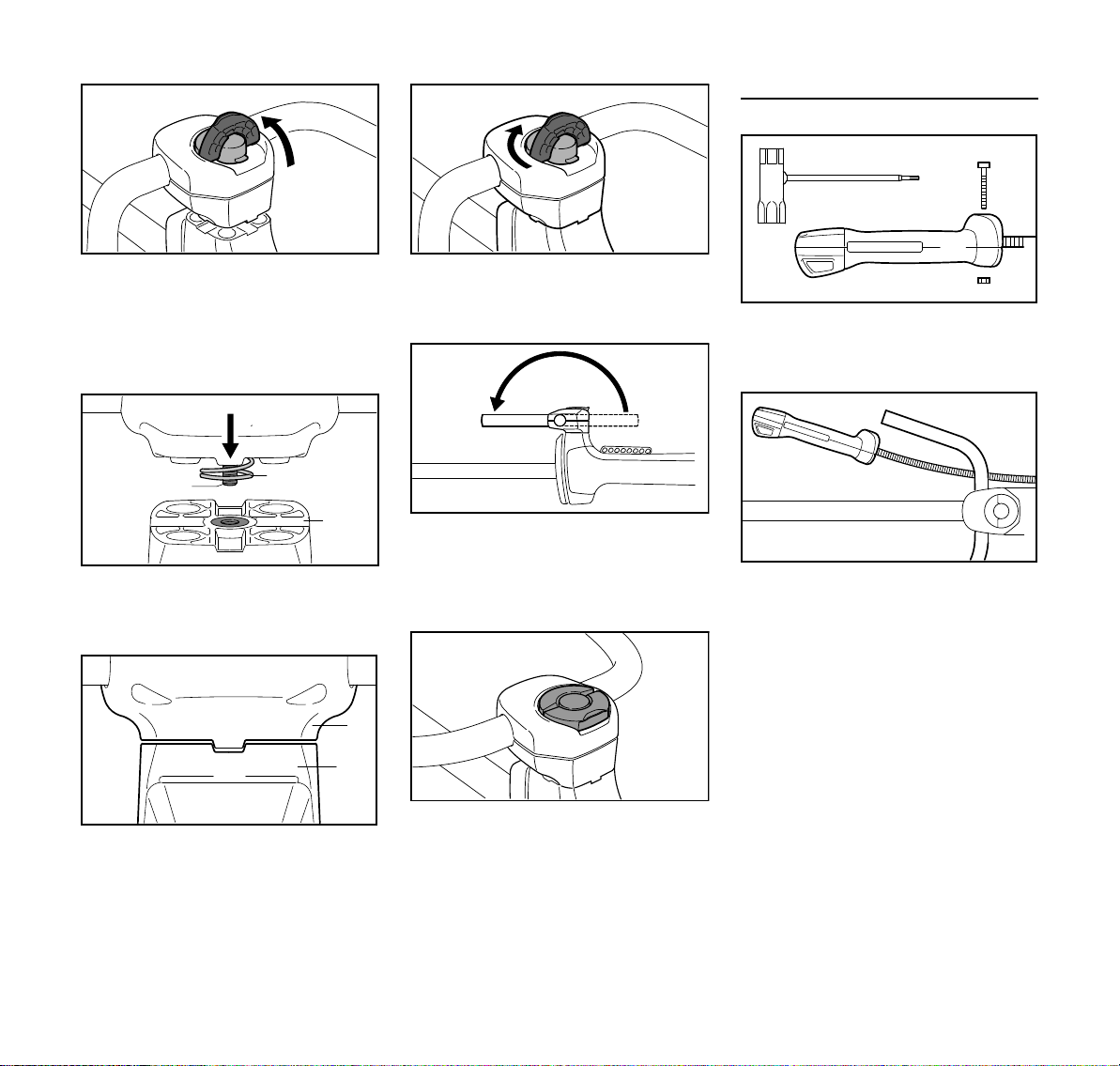
Mounting the Bike Handle
1
3BA003 KN
3BA004 KN
4
2
2BA001 KN
4
3
3BA005 KN
5
4900BA002 KN
7
2
4
Mounting Bike Handle with Swiveling
Handle Support
English
Do not rotate the control handle (1)
between unpacking and mounting it on
the handlebar; see also chapter on
"Adjusting the Throttle Cable".
The brushcutter is available with two
different handlebars:
2 Handlebar for machines used
primarily for mowing, brushcutting
and shredding, but also for
occasional sawing.
3 Handlebar for machines used
mainly for sawing, but also for
mowing and brushcutting.
The machine is supplied with the clamp
moldings (4) mounted on the handlebars
(2, 3).
N Do not change the position of the
clamp moldings on the handlebar
until it is mounted on the handle
support.
The mounting procedure is the same for
both types of handlebar. Therefore, the
following description only shows
handlebar (2).
Mounting the Handlebar
Assembly of the swivelling handle
support involves equipping the clamp
moldings with a spring and mounting
them on the handle support.
N Use the spring (5) from the parts kit
supplied with the machine.
N Push the spring (5) into the lower
clamp molding (6).
N Position the clamp moldings (4) with
handlebar (2) on the handle support
(7).
N Do not turn the handlebar in the
clamp moldings.
FS 561 C-M
15
English
8
3BA007 KN
5
8
3BA008 KN
7
6
10
7
9
3BA0009 KN
7
6
3BA010 KN
2
4900BA003 KN
4900BA004 KN
11
12
1
002BA451 KN
13
2
4900BA005 KN
Mounting the Control Handle
N Raise the grip of the wing screw (8)
to the upright position.
N Rotate the wing screw
counterclockwise and tighten it only
moderately.
N Position wing screw (8) in threaded
insert in handle support (7) – against
pressure of spring (5).
N Rotate wing screw clockwise until
the lower clamp molding (6) butts
against the handle support (7).
N Swing the handebar (2) forwards
through 180°.
N Only tighten the wing screw
moderately.
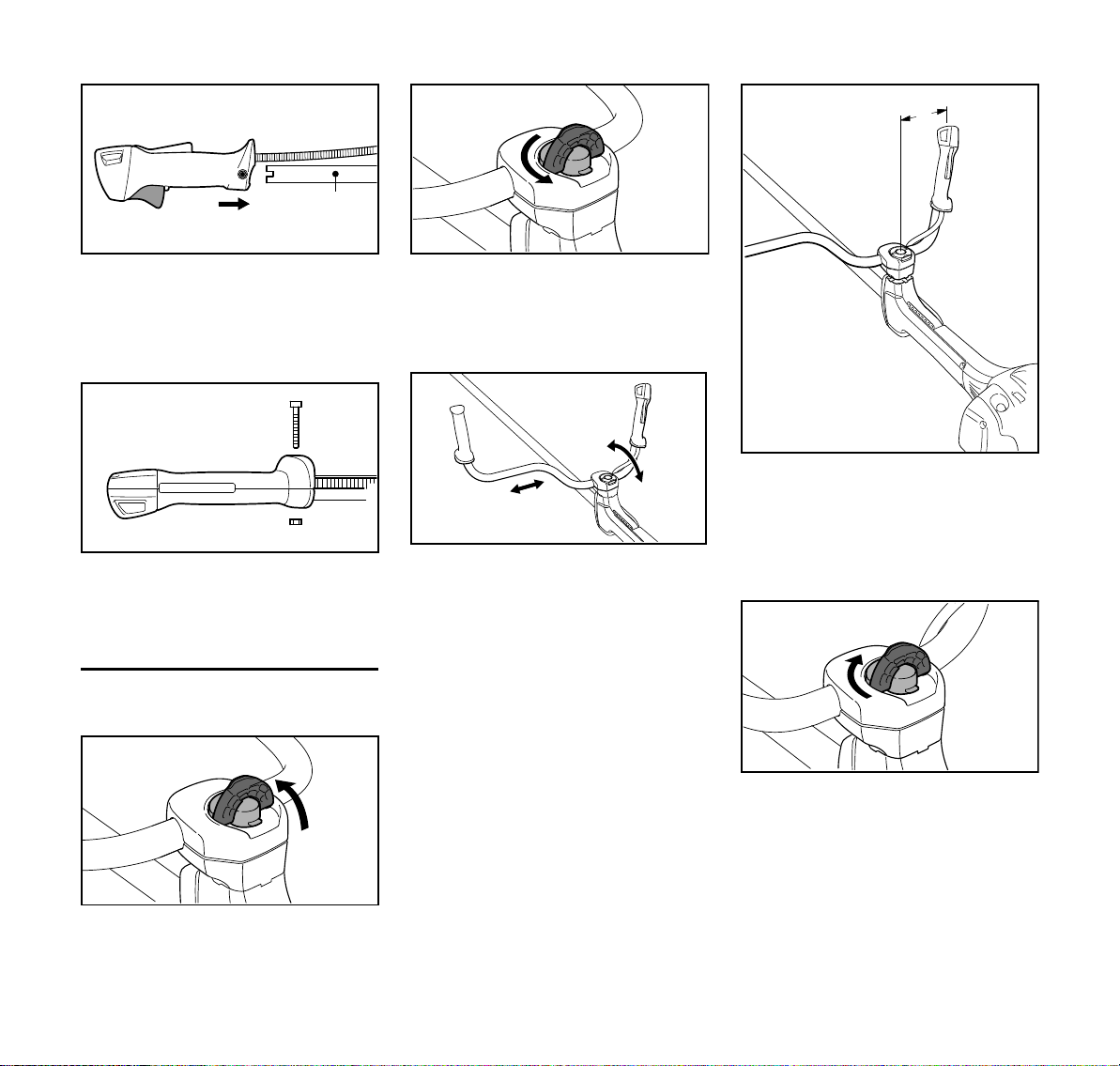
N Take out the screw (11) and remove
the nut (12) from the control handle
(1).
N Hold the control handle in front of
the right-hand end of the handlebar
so that the throttle cable (13) is on
the inboard side of the handlebar
(2).
N Position the clamp moldings so that
the tabs (9) on the lower clamp
molding (6) line up with the slots
(10) in the handle support (7).
16
N Fold the grip of the wing screw down
so that it is flush.
FS 561 C-M
English
14
15
15
2
4900BA007 KN
1
11
12
4900BA008 KN
4900BA009 KN
4900BA010 KN
4900BA011 KN
4900BA012 KN
2
A
4900BA013 KN
N Push the control handle (1) in this
position onto the end of the
handlebar (2) until the holes (15)
line up – throttle trigger (14) facing
down.
N Fit the nut (12) in the control handle,
insert the screw (11) and tighten it
down firmly.
Adjusting the Handlebar
Opening the wing screw
N Turn the wing screw
counterclockwise until the handle
support can be moved.
Lining up the handlebar
N Move the handlebar to the required
position.
N Position the handlebar (2) so that
distance A is about 7 in (17 cm).
Do not clamp the curved part of the
handlebar.
Closing the wing screw
N Rotate the wing screw clockwise
until it becomes difficult to turn.
N Tighten down the wing screw firmly.
N Raise the grip of the wing screw to
the upright position.
FS 561 C-M
17

English
4900BA014 KN
4900BA015 KN
2
8
002BA655 KN
N Fold the grip of the wing screw down
so that it is flush.
Checking the Throttle Cable
N After mounting the control handle,
check the throttle cable – see
chapter on "Adjusting the Throttle
Cable".
Swiveling the Handlebar
Transport position
N Loosen the wing screw (8) and
unscrew it until the handlebar (2)
can be turned clockwise.
N Turn the handlebar 90° and then
swing the handles down.
N Tighten down the wing screw (8)
firmly.
Working position
N Reverse the sequence described
above to swing the handles up and
turn the handlebar
counterclockwise.
Adjusting the Throttle Cable
It may be necessary to correct the
adjustment of the throttle cable after
assembling the machine or after a
prolonged period of operation.
Adjust the throttle cable only when the
unit is completely and properly
assembled.
N Set the throttle trigger to the full
throttle position.
N Carefully rotate the screw in the
throttle trigger in the direction of the
arrow until you feel initial resistance.
Then rotate it another half turn in the
same direction.
18
FS 561 C-M
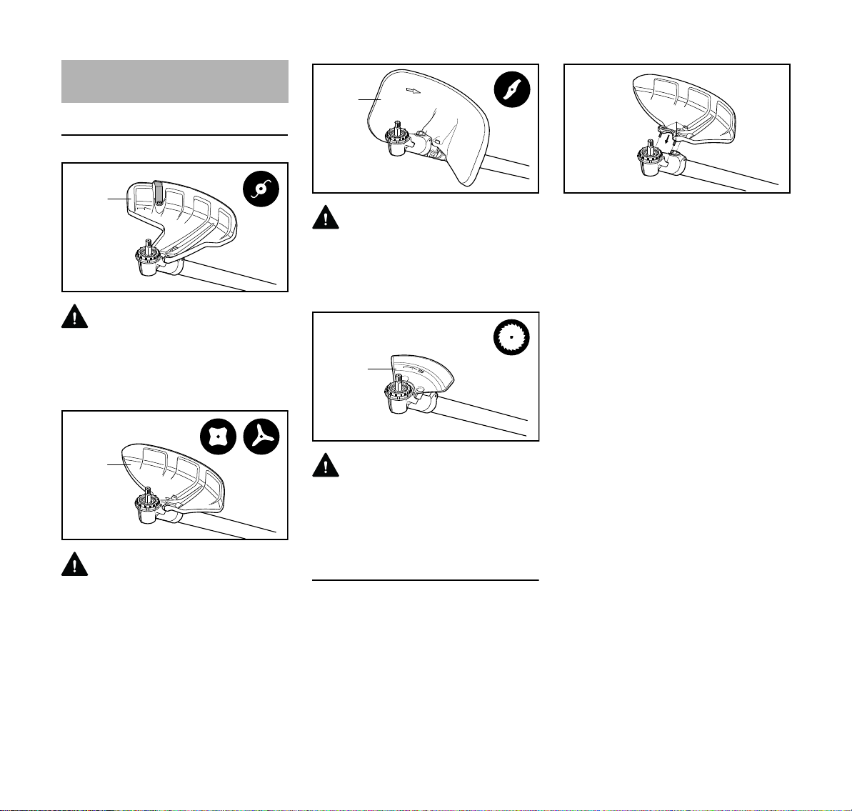
Mounting the Deflector
1
002BA461 KN
2
002BA462 KN
3
002BA463 KN
4
002BA464 KN
5
6
002BA465 KN
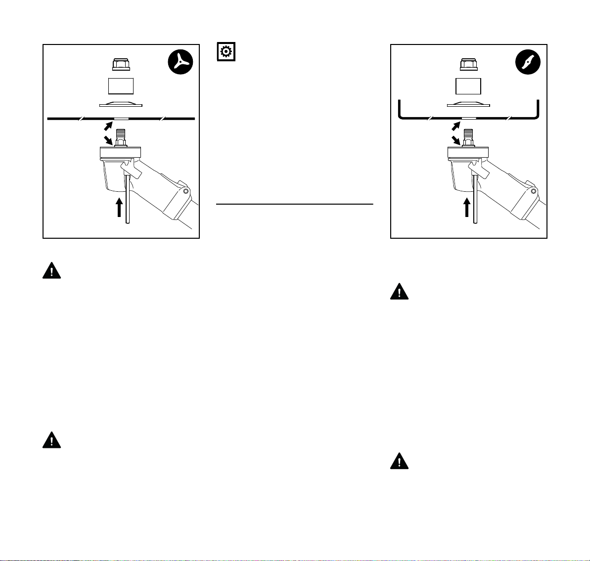
Using the Proper Deflector
English
WARNING
Deflector (1) is approved only for
mowing heads, thus deflector (1) must
be attached before attaching a mowing
head.
WARNING
Deflector (2) is approved only for grass
cutting blades and brush knives, thus
deflector (2) must be attached before
attaching a grass cutting blade or brush
knife.
FS 561 C-M
WARNING
Deflector (3) is approved only for
shredder blades, thus deflector (3) must
be attached before attaching a shredder
blade, see section "Mounting deflector".
WARNING
Limit stop (4), which acts as a deflector,
is approved only for circular saw blades,
thus limit stop (4) must be attached
before attaching a circular saw blade.
Mounting the guard
Deflectors (1, 2 and 4) are mounted to
the gearbox in the same way.
N Remove dirt from joints on gearbox
and deflector – make sure that no
dirt gets into the screw holes in the
gearbox – see section on "Plugs"
N Place the deflector on the gearbox
(5)
N insert the screws (6) and tighten
them down to a torque of 89 lbf. in.
(10 Nm).
Mounting shredder deflector
Owing to the high loads on the shredder
deflector (3) and country-specific
regulations on the use of the machine for
shredding, the deflector must be
properly mounted to the machine.
A special screwdriver bit is required to
mount this deflector. The bit is available
only from specialist retailers. It has a
special drive for rotating the screws and
only allows the screws to be tightened.
Once tightened, the screws can no
longer be loosened – not even with the
special tool!
STIHL therefore recommends: Have the
shredder deflector mounted by your
STIHL dealer.
A "shredder deflector mounting kit" is
available as a special accessory for
retrofitting machines with a shredder
deflector. Depending on the machine's
original equipment, a "shredder blade
19
English
002BA495 KN
3
2
2
002BA496 KN
5
5
3
002BA497 KN
1
4
002BA498 KN
002BA499 KN
retrofit kit" may also be needed for the
conversion. Neither of these kits include
the shredder blade – it must be ordered
separately.
The "shredder blade retrofit kit" contains
clamps which butt against the gearbox
and have to be secured to the drive tube.
The kit also contains the shredder
deflector which is mounted to the
clamps.
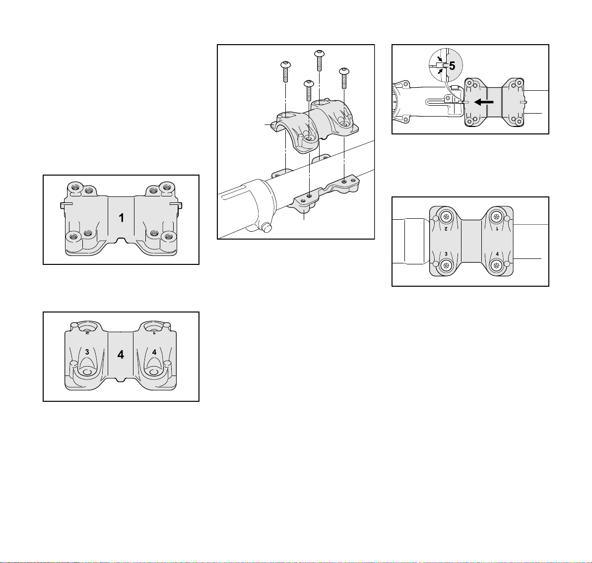
– Installing the clamps
– Lower clamp (1): Identified by two
lugs (2) on its longitudinal axis, eight
tapped holes and a lateral notch (3)
– Upper clamp (4): Identified by holes
marked 1 to 4 and a lateral lug (5)
N Position the lower clamp (1) against
the underside of the drive tube next
to the gearbox
N position the upper clamp (4) on the
drive tube so that the lug (5)
engages the notch (3)
N hold both clamps steady in this
position
N insert a screw in the upper clamp (4)
in the hole marked with number 1
and turn it only a few turns in the
lower clamp (1)
N Insert a screw in each of the holes
marked 2, 3 and 4 and wind them
only a few turns into the lower clamp
N Slide the clamps up against the
gearbox and engage the lug (5) in
the gearbox gap (arrows)
N hold both clamps in this position!
N Screw home the screws in holes 1
and 2 as far as stop
N Tighten down the screws in holes 1
and 2 to a torque of 8 Nm
N Screw home the screws in holes 3
and 4 in that order and tighten them
down to a torque of 8 Nm
20
FS 561 C-M
English
6
002BA500 KN
002BA466 KN
8
9
6
002BA406 KN
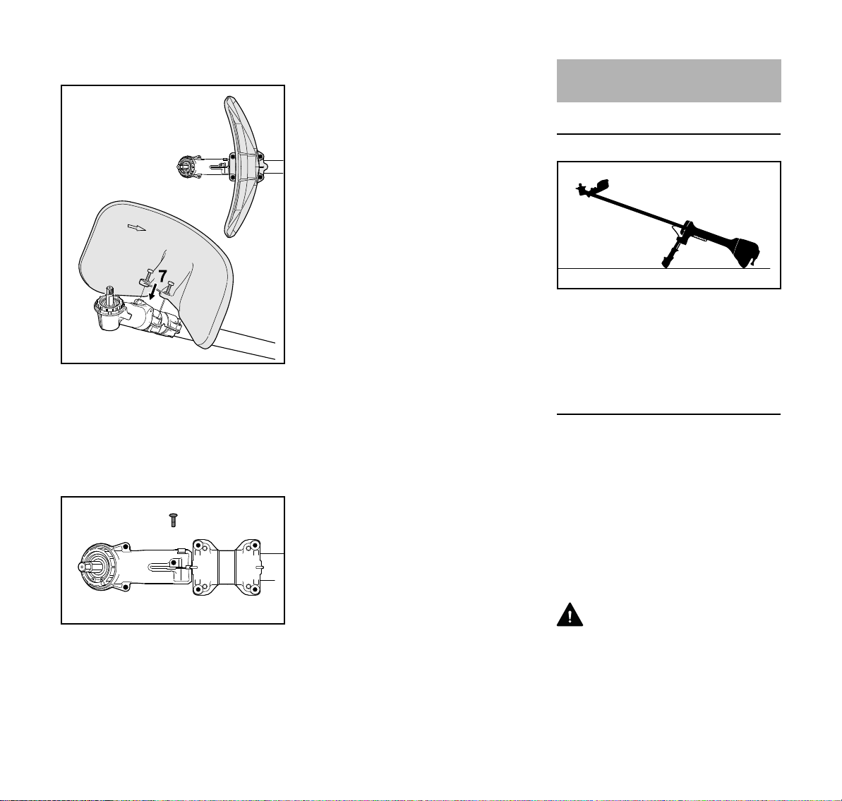
– Mounting the shredder deflector
N Position the shredder deflector on
the lower clamp with its concave
side facing the gearbox (6)
N Screw in and tighten the screws (7)
– Plugs
Four plugs (9) are supplied with the
shredder deflector.
Mounting the Cutting
Attachment
Placing power tool on the ground
N Shut off the engine.
N Lay your power tool on its back so
that the cutting attachment
mounting face is pointing up.
Mounting Hardware for the Cutting
Attachment
The mounting hardware supplied
depends on the cutting attachment that
comes as original equipment with the
new machine.
The appropriate deflectors and
mounting hardware are available as
special accessories for subsequently
equipping the machine with different
cutting attachments – see chapter on
"Special Accessories".
To prevent the unused threaded holes
for protection in the gear unit (6) and
clamps (8) from becoming
contaminated, plugs (9) are available as
optional accessories.
FS 561 C-M
WARNING
Always use and assemble the cutting
attachment mounting hardware as
described in the chapter on "Mounting
the Cutting Attachment".
21

English
681BA191 KN
4
3
4
681BA192 KN
5
Thrust Plate
A
– For fixing mowing heads, grass
cutting blades, brush knives,
shredder blades and circular saw
blades
NOTICE
The thrust plate is needed to mount all
cutting attachments on the gearbox.
Thrust washer
A
– For fixing grass cutting blades,
brush knives, shredder blades and
circular saw blades
Rider plates, guard ring and nut
A
681BA188 KN
– For fixing grass cutting blades,
brush knives and circular saw
blades
– Guard ring (3) for brush knives and
shredder blades
Both these parts have the same
function:
– Nut (4) and thread on shaft are
681BA189 KN
protected against wear.
– Ground contact with metal cutting
attachment is minimized.
– Rider plates allow the cutting
attachment to glide along close to
ground.
Nut and combination wrench
681BA190 KN
Metal cutting attachments are mounted
to the gearbox with the nut (4).
N Loosen and tighten the nut (4) with
the combination wrench (5).
WARNING
Nuts that move too easily must be
replaced.
Cleaning gearbox and mounting
hardware for the cutting attachment
The gearbox, its surroundings, the
interior of the shield and the individual
mounting hardware for the cutting
attachment should be inspected for dirt
regularly and when changing the cutting
attachment and thoroughly cleaned if
necessary. To do this:
N Remove all mounting hardware for
the cutting attachment from the
gearbox
WARNING
Always replace a worn rider plate and
guard ring in good time.
22
FS 561 C-M
English
002BA467 KN
1
2
002BA507 KN
1
2
3
1
002BA468 KN
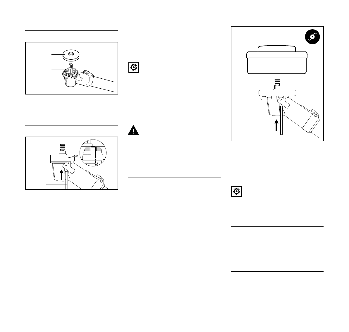
Attaching the thrust plate
N Slip the thrust plate (1) over the
shaft (2).
Retaining the Shaft
The shaft (2) must be blocked to install
and remove cutting attachments.
The shaft (2) can be blocked only if the
thrust plate (1) is properly fitted – the
stop pin (3) has to engage the thrust
plate.
N Insert the stop pin (3) in the bore in
the gearbox – apply slight pressure.
N Turn the shaft, nut or cutting
attachment until the stop pin
engages and the shaft is blocked
The stop pin is held in position in the
gearbox by a rubber element.
FS 561 C-M
N Fit or remove the cutting attachment
– see chapter on "Mounting the
Cutting Attachment"
N Remove the stop pin from the
gearbox
NOTICE
Always remove the stop pin used to
block the shaft since the drive train will
otherwise be damaged when the engine
runs.
Mounting the Cutting Attachment
WARNING
Use a deflector that matches the cutting
attachment – see "Mounting the
Deflector".
Fitting the mowing head with screw
mounting
Keep the supplement sheet for the
mowing head in a safe place.
All approved mowing heads are
mounted to the gearbox in the same
way.
N Check whether the fitted deflector is
approved for mowing heads – if not,
remove the deflector not approved
for mowing heads
N Mount the deflector for mowing
heads
N Attaching the thrust plate
N Turn the mowing head
anticlockwise on the shaft (1) as far
as it will go
N Retain the shaft
N Tighten the mowing head
NOTICE
Remove the tool that was used to block
the shaft.
Removing the Mowing Head
N Retain the shaft
N Turn the mowing head clockwise
Mounting and removing the metal
cutting attachment
To mount and remove metal cutting
attachments:
23
English
1
2
681BA186 KN
a
002BA469 KN
b
4
5
3
6
1
2
681BA187 KN
WARNING
Put on protective gloves – risk of injury
by the sharp cutting edges
Mounting Grass Cutting Blades or Brush
Knives
N check whether the fitted deflector is
approved for grass cutting blades or
brush knives – if not, remove the
deflector not approved for grass
cutting blades or brush knives
N Mount the deflector for grass cutting
blades and brush knives
N Attaching the thrust plate
Positioning the cutting attachment
The cutting edges of the grass cutting
blades with more than 4 blades must
point clockwise.
N Position the cutting attachment (3)
WARNING
The collar (a) must engage the hole (b)
in the cutting attachment!
Securing the cutting attachment
N Fit the thrust washer (4) – curvature
faces upward
N Fit the rider plate (5)
N Retain the shaft
N Screw on the nut (6)
counterclockwise and tighten it
down firmly
NOTICE
Remove the tool that was used to block
the shaft.
Removing the cutting attachment
N Retain the shaft
N Unscrew the mounting nut (6)
clockwise.
N Remove the cutting attachment and
its mounting hardware from the
gearbox
Mounting the brush knife (with protective
ring)
N Check whether the fitted deflector is
approved for brush knives – if not,
remove the deflector not approved
for brush knives
N Mount the deflector for grass cutting
blades and brush knives
N Using the thrust plate
Positioning the cutting attachment
24
WARNING
Nuts that move too easily must be
replaced.
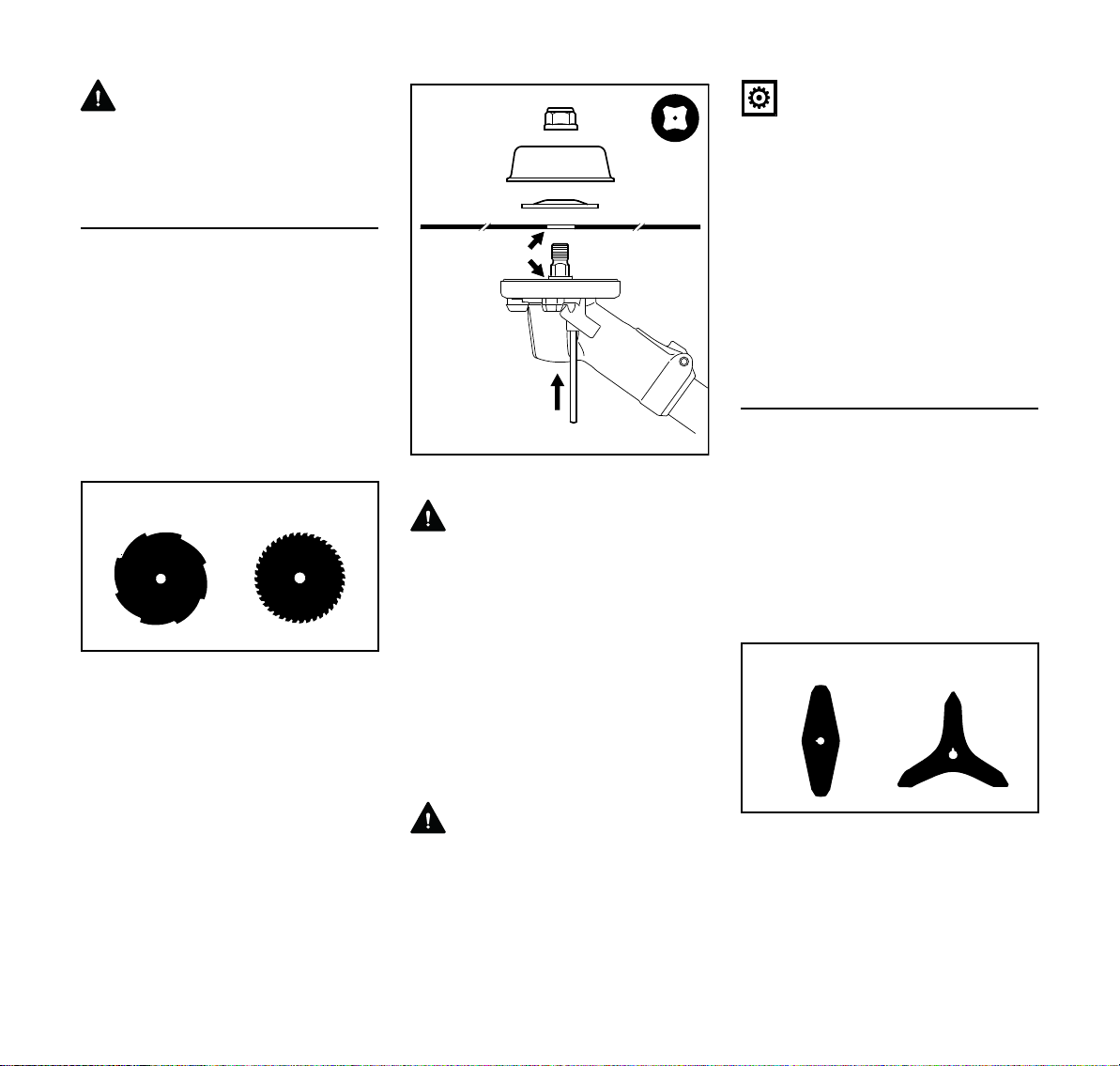
Brush knives 305-2 (1) and 350-3(2)
may point in either direction – these
cutting attachments must be turned over
regularly to help avoid one-sided wear.
FS 561 C-M
N Position the cutting attachment (3)
3
002BA494 KN
3
6
4
b
a
5
002BA470 KN
3
4
2
1
b
a
WARNING
The collar (a) must engage the hole (b)
in the cutting attachment!
Securing the cutting attachment
N Fit the thrust washer (4) – curvature
faces upward
N Fit the guard ring (5) for brush
knives – opening must face up
N Retain the shaft
N Screw on the nut (6)
counterclockwise and tighten it
down firmly
WARNING
Nuts that move too easily must be
replaced.
NOTICE
Remove the tool that was used to block
the shaft.
Removing the cutting attachment
N Retain the shaft
N Unscrew the mounting nut
clockwise
N Remove the cutting attachment and
its mounting hardware from the
gearbox
Mounting shredder blade 320-2
N Check whether the fitted deflector is
approved for shredder blades – if
not, remove the deflector not
approved for shredder blades
N Mounting deflector for shredder
blade
N Using the thrust plate
N Seal the unused tapped holes with
plugs
English
N Place the shredder blade (1) in
position – the cutting edges must
point upwards
WARNING
The collar (a) must engage the hole (b)
in the cutting attachment!
Securing the cutting attachment
N Fit the thrust washer (2) – curvature
faces upward
N Fit the shredder blade guard ring (3)
– opening must face up.
N Retain the shaft
N Screw on the nut (4)
counterclockwise and tighten it
down firmly
WARNING
Nuts that move too easily must be
replaced.
FS 561 C-M
25

English
681BA165 KN
2
1
4
002BA471 KN
3
b
a
NOTICE
Remove the tool that was used to block
the shaft.
Removing the cutting attachment
N Retain the shaft
N Unscrew the mounting nut
clockwise
N Remove the cutting attachment and
its mounting hardware from the
gearbox
N If you intend to use a different
cutting attachment – remove the
shredder deflector.
Mounting Circular Saw Blades 225
N Check whether the stop for circular
saw blades is already mounted to
the machine
N If mounted, remove the deflector
N Mount the limit stop for circular saw
blades
N Using the thrust plate
N Seal the unused tapped holes with
plugs
Positioning the cutting attachment
With circular saw blades, the cutting
edges must face clockwise.
N Retain the shaft
N Screw on the nut (4)
counterclockwise and tighten it
down firmly
WARNING
Nuts that move too easily must be
replaced.
NOTICE
Remove the tool that was used to block
the shaft.
Removing the cutting attachment
N Retain the shaft
N Unscrew the mounting nut
clockwise
N Remove the cutting attachment and
its mounting hardware from the
gearbox
26
N Position the cutting attachment (1)
WARNING
The collar (a) must engage the hole (b)
in the cutting attachment!
Securing the cutting attachment
N Fit the thrust washer (2) – curvature
faces upward
N Fit the rider plate (3)
FS 561 C-M

English
Fuel
This engine is certified to operate on
unleaded gasoline and with the mix ratio
50:1.
Your engine requires a mixture of highquality premium gasoline and highquality two-stroke air-cooled engine oil.
Use premium branded unleaded
gasoline with a minimum octane rating
of 89 (R+M)/2.
Note: Models equipped with a catalytic
converter require unleaded gasoline. A
few tankfuls of leaded gasoline can
reduce the efficiency of the catalytic
converter by more than 50%.
Fuel with a lower octane rating may
result in preignition (causing "pinging")
which is accompanied by an increase in
engine temperature. This, in turn,
increases the risk of the piston seizure
and damage to the engine.
The chemical composition of the fuel is
also important. Some fuel additives not
only detrimentally affect elastomers
(carburetor diaphragms, oil seals, fuel
lines etc.), but magnesium castings as
well. This could cause running problems
or even damage the engine. For this
reason it is essential that you use only
high-quality fuels!
Fuels with different percentages of
ethanol are being offered. Ethanol can
affect the running behaviour of the
engine and increase the risk of lean
seizure.
Gasoline with an ethanol content of
more than 10% can cause running
problems and major damage in engines
with a manually adjustable carburetor
and should not be used in such engines.
Engines equipped with M-Tronic can be
run on gasoline with an ethanol content
of up to 25% (E25).
Use only STIHL two-stroke engine oil or
equivalent high-quality two-stroke aircooled engine oils for mixing.
We recommend STIHL 50:1 two-stroke
engine oil since it is specially formulated
for use in STIHL engines.
To ensure the maximum performance of
your STIHL engine, use a high quality 2cycle engine oil. To help your engine run
cleaner and reduce harmful carbon
deposits, STIHL recommends using
STIHL HP Ultra 2-cycle engine oil or ask
your dealer for an equivalent fully
synthetic 2-cycle engine oil.
To meet the requirements of EPA and
CARB we recommend to use STIHL HP
Ultra oil.
Do not use BIA or TCW (two-stroke
water cooled) mix oils!
Use only STIHL 50:1 heavy-duty engine
oil or an equivalent quality two-stroke
engine oil for the fuel mix in models
equipped with a catalytic converter.
Take care when handling gasoline.
Avoid direct contact with the skin and
avoid inhaling fuel vapour.
The canister should be kept tightly
closed in order to avoid any moisture
getting into the mixture.
The fuel tank and the canister in which
fuel mix is stored should be cleaned
from time to time.
Fuel mix ratio
Only mix sufficient fuel for a few days
work, not to exceed 30 days of storage.
Store in approved safety fuel-canisters
only. When mixing, pour oil into the
canister first, and then add gasoline.
Examples
Gasoline Oil (STIHL 50:1 or equiva
lent high-quality oils)
liters liters (ml)
1 0.02 (20)
5 0.10 (100)
10 0.20 (200)
15 0.30 (300)
20 0.40 (400)
25 0.50 (500)
Dispose of empty mixing-oil canisters
only at authorized disposal locations.
-
FS 561 C-M
27

English
4900BA016 KN
2709BA003 KN
2709BA004 KN
3
002BA411 KN
1
2
Fueling
Preparations
WARNING
When fueling on a slope, always position
the machine with the filler cap facing
uphill.
N On level ground, position the
machine so that the filler cap is
facing up.
N Before fueling, clean the filler cap
and the area around it to ensure that
no dirt falls into the tank.
28
Opening the filler cap
N Turn the cap counterclockwise until
it can be removed from the tank
opening.
N Remove the cap.
Filling Up with Fuel
Take care not to spill fuel while fueling
and do not overfill the tank.
STIHL recommends you use the STIHL
filler nozzle for fuel (special accessory).
N Fill up with fuel.
Closing the filler cap
N Place the cap in the opening.
N Turn the cap clockwise as far as
stop and tighten it down as firmly as
possible by hand.
Fitting the Full Harness
Fitting the full harness is described in
detail in the leaflet supplied with the
harness.
The type and style of the harness
depend on the market.
Fitting the Harness
N Put on the full harness (1).
N Adjust the length of the strap so that
the carabiner (2) is about a hand’s
width below your right hip.
N Attach the carabiner to the
machine's perforated rail (3) – see
“Attaching Machine to Harness”.
N Find the right attachment point for
the cutting attachment you are
using – see "Balancing the
Machine".
FS 561 C-M

English
2
1
002BA631 KN
1
2
2
1
002BA632 KN
1
2
6BA009 KN
6BA010 KN
Attaching Machine to Harness
N Attach the carabiner (1) to the
perforated rail (2) on the drive tube.
Disconnecting Machine from Harness
N Press down the bar on the
carabiner (1) and pull the perforated
rail (2) out of the carabiner.
Balancing the Machine
The machine will balance differently
depending on the cutting attachment
mounted.
N Let the machine swing on the
harness until it stops moving –
change the connection point if
necessary
Hanging positions
Mowing heads, grass cutting blades,
brush knives and shredder blades
should rest lightly on the ground.
Putting down the machine in an
emergency
WARNING
As soon as it becomes apparent that a
dangerous situation is developing, the
machine must be put down quickly.
Practice setting down the machine
quickly. In order to avoid damage, when
practicing, do not throw the machine on
the ground.
FS 561 C-M
Circular saw blades should "hover"
approx. 20 cm above the ground.
29

English
1
002BA474 KN
2
3
002BA481 KN
4
4900BA017 KN
5
4900BA018 KN
6BA011 KN
Starting / Stopping the
Symbols on choke knob
Engine
Controls
N If the engine is cold: Depress in the
Run position F – a hot engine is started
in this position or the engine runs in this
position.
Start position } – a cold engine is
started in this position.
Starting the Engine
1 Throttle trigger lockout
2 Throttle trigger
3 Stop switch with Run and Stop
positions. Depress the stop switch
(…) to switch off the ignition.
Function of stop switch and ignition
system
The stop switch is normally in the Run
position, i.e. when it is not depressed:
The ignition is switched on – the engine
is ready to start. Operate the stop switch
to switch off the ignition. The ignition is
switched on again automatically after
the engine stops.
N Press the manual fuel pump
bulb (4) at least five times – even if
the bulb is filled with fuel.
The choke knob is in the normal run
position F.
outer edge (arrows) of the choke
knob (5) and then turn it to Start }.
Cranking
N Place the unit on the ground: It must
rest securely on the engine's guard
plate and the deflector. Check that
the cutting attachment is not
touching the ground or any other
obstacles.
N Make sure you have a firm footing,
either standing, stooping or
kneeling.
N Hold the unit firmly on the ground
with your left hand and press down
– do not touch the throttle trigger or
throttle trigger lockout.
NOTICE
Do not stand or kneel on the drive tube.
30
FS 561 C-M

Stopping the Engine
6BA012 KN
6BA014 KN
002BA485 KN
6BA024 KN
English
N Hold the starter grip with your right
hand.
NOTICE
Do not pull out the starter rope all the
way – it might otherwise break.
N Do not let the starter grip snap back.
Guide it slowly back into the housing
so that the starter rope can rewind
properly.
N Continue cranking until the engine
runs.
N If the engine does not start: Turn the
choke knob to the start position }
and repeat starting procedure.
Using the Machine
If you have started the machine for the
first time, refer to the notes on "Starting
for first time" in section "Other Hints on
Starting".
N If the engine was started in the start
position }: Briefly press down the
trigger lockout and the pull the
throttle trigger at the same time –
the choke knob moves to the run
position (F) and the engine settles
down to idling speed.
Your machine is now ready for
operation.
WARNING
The cutting attachment must not rotate
in the Run F position with the engine at
idling speed.
If the cutting attachment rotates when
the engine is idling, refer to notes in
chapter on "Adjusting the Throttle
Cable" or have the machine serviced by
your dealer. STIHL recommends an
authorized STIHL servicing dealer.
N Attach the machine to the shoulder
strap.
N Machine is ready for use.
N Depress the momentary contact
stop switch – the engine stops –
release the stop switch – it springs
back to the run position.
Other Hints on Starting
Starting for first time
N Depress the throttle trigger – do not
press down the throttle trigger
lockout.
If engine speed increases or the cutting
attachment rotates:
N Go to section "Stopping the
Engine".
N Go to "Adjusting the Throttle Cable".
If the engine speed does not increase,
your machine is ready for operation.
FS 561 C-M
31

English
681BA301 KN
681BA275 KN
1.
2.
0000-GXX-0423-A0
681BA281 KN
2.
At very low outside temperatures
N Set the engine to winter operation if
necessary, see "Winter Operation".
N If the machine is very cold (frost on
machine), allow the engine to warm
up in the start position } after
starting until normal operating
temperature is reached. Warning:
The cutting attachment runs.
At very high outside temperatures
If the engine does not start after 10 pulls
in the Start } position:
N Start the engine in the Run F
position.
If the engine does not start
N Check that all settings are correct.
N Check that there is fuel in the tank
and refuel if necessary.
N Check that the spark plug boot is
properly connected.
N Repeat the starting procedure.
Engine is flooded
N Move the choke knob to F and
continue cranking until the engine
runs.
Fuel tank run until completely dry
N After refueling, press the manual
fuel pump bulb at least five times –
even if the bulb is filled with fuel.
N Now start the engine.
Transporting the Unit
Using Transport Guard
The type of transport guard depends on
the metal cutting attachment supplied
with the machine. Transport guards are
available as special accessories.
Grass cutting blades, 250 and 255
N Disconnect wire rod from the
transport guard.
N Swing wire rod outwards.
N Fit the transport guard on the cutting
attachment from below.
N Hook wire rod to the transport
guard.
N Swing wire rod into position.
32
FS 561 C-M

English
681BA302 KN
681BA275 KN
1.
2.
681BA276 KN
681BA277 KN
2.
681BA293 KN
681BA294 KN
1.
2.
2.
681BA295 KN
Circular saw blades, 225
N Disconnect wire rod from the
transport guard.
Universal transport guard for metal
cutting attachments
The universal transport guard can be
used for shredder blades, grass cutting
blades and brush knives.
N Swing wire rod outwards.
N Fit the transport guard on the cutting
attachment from below, making
sure the limit stop is properly seated
in the recess.
N Disconnect wire rod from the
transport guard and swing it
outwards.
FS 561 C-M
N Swing wire rod into position.
N Hook wire rod to the transport
guard.
N Fit the transport guard on the cutting
attachment from below.
N Attach wire rod to the hook on the
transport guard.
33

English
4900BA019 KN
1
4900BA020 KN
3
2
Operating Instructions Air filter
During break-in period
A factory-new machine should not be
run at high revs (full throttle off load) for
the first three tank fillings. This avoids
unnecessary high loads during the
break-in period. As all moving parts
have to bed in during the break-in
period, the frictional resistances in the
engine are greater during this period.
The engine develops its maximum
power after about 5 to 15 tank fillings.
During Operation
After a long period of full throttle
operation, allow the engine to run for a
short while at idle speed so that engine
heat can be dissipated by the flow of
cooling air. This protects enginemounted components (ignition,
carburetor) from thermal overload.
After Finishing Work
Storing for a short period: Wait for the
engine to cool down. Empty the fuel tank
and keep the machine in a dry place,
well away from sources of ignition, until
you need it again. For longer out-ofservice periods – see "Storing the
Machine".
Basic information
The filter has an extremely long service
life.
Do not dismantle the filter cover and fit a
new air filter unless there is a noticeable
loss of engine power.
Soiled air filters reduce the engine
power, increase the fuel consumption,
and hinder engine start-up.
Changing the air filter
Only if there is a noticeable loss of
engine power
N Set the choke lever to }
N Undo the fixing screws (1)
N Remove the filter cover (2)
N Remove coarse dirt from inside the
filter cover and around the filter (3)
The filter (3) filters the air through
pleated paper.
N Remove and check the filter
element (3) – replace if paper or
frame is dirty or damaged.
N Unpack the new filter
NOTICE
Do not bend or twist the filter before
installation as it might otherwise be
damaged – do not use damaged filters.
N Insert filter in filter housing
N Attach filter cover
Only use high-quality air filters so that
the engine is protected from the entry of
abrasive dust.
STIHL recommends the use of original
STIHL air filters. The high quality
standard of these spare parts
guarantees smooth operation, a long
engine service life and very long filter
service lives.
34
FS 561 C-M

English
1
min
AB C
s> 30 s30-60 s
0000-GXX-4580-A0
Filter insert for winter operation
Maintenance and care of the special
filter insert for winter operation are
described in the section "Winter
operation".
Engine Management M-Tronic
Exhaust emissions are controlled by the
design of the engine and components
(e.g. carburation, ignition, timing and
valve or port timing).
The clearing saw adjusts itself
automatically for optimum performance
during operation. Calibration enables
the clearing saw to be adjusted faster for
optimum performance.
N Remove mowing head or metal
cutting attachment. This allows the
clearing saw to reliably adjust to the
optimum performance.
If the external temperature is below 10°C or the engine is cold:
N Start the engine.
N warm up engine for about 1 minute
by blipping the throttle.
N Shut off the engine.
To calibrate the clearing saw, carry out
the following steps:
FS 561 C-M
N Set the master control lever to }
position.
N Start the engine without depressing
the throttle trigger. The engine runs
and the master control lever
remains in position }.
N Run the engine for at least 30
seconds but no more than 60
seconds without depressing the
throttle trigger.
35

English
2
1
9926BA016 KN
2
9926BA017 KN
3
NOTICE
The calibration process is aborted if the
throttle trigger is released before the
clearing saw is properly calibrated. It is
then necessary to restart the calibration
process.
N Keep the throttle trigger fully
depressed.
NOTICE
The clearing saw may be incorrectly
calibrated if the throttle trigger is not kept
fully depressed during calibration. The
clearing saw may be damaged.
N Keep the throttle trigger fully
depressed.
N tDepress the throttle trigger for at
least 30 seconds and hold it in that
position.
The engine accelerates and the clearing
saw is calibrated. The engine speed
fluctuates and increases perceptibly
during calibration.
If the engine stops:
N Try again to calibrate the clearing
saw.
If the engine keeps stalling:
N Do not use the clearing saw.
Consult a STIHL dealer. The
clearing saw is faulty.
As soon as the engine speed drops
noticeably:
N Release the throttle trigger.
The engine runs at idling speed. Your
clearing saw is calibrated and ready for
operation.
Winter Operation
At temperatures below +10 °C
Preheating the carburetor
Repositioning a shutter allows heated air
to be drawn in from around the cylinder
and mixed with cold air – this helps
prevent carburetor icing.
An arrow (1) on the shroud indicates the
setting of the shutter (2) for summer or
winter operation. Meaning of symbols:
– "Sun" = summer operation
– "Snowflake" = winter operation
N Remove the screw (3) from the
shutter.
N Pull the shutter (2) out of the shroud.
N Rotate the shutter (2) from the
summer position to the winter
position and refit it.
N Secure the shutter in position with
the screw (3).
At temperatures between +10°C and
+20°C
The machine can normally be operated
in this temperature range with the
shutter (2) in the summer position.
Change the position of the shutter if
necessary.
36
FS 561 C-M

English
2
9926BA018 KN
4900BA021 KN
4
2
5
At temperatures above +20°C
N Always return the shutter (2) to the
summer position.
NOTICE
Do not operate the machine in the winter
position at temperatures above +20°C
because there is otherwise a risk of
engine running problems and
overheating.
At temperatures below -10°C
In extreme wintry conditions
– Temperatures below -10°C
– Powder or drifting snow
it is advisable to use the optional "cover
plate kit".
The cover plate kit contains the following
parts for converting the power tool:
4 Cover plate partially blanks off the
slots in the starter housing
5 Synthetic fabric filter element for the
air filter
– Instructions for converting the
machine
After installing the cover plate kit:
N Set the shutter (2) to the winter
position.
At temperatures above -10 °C
N Remove the parts of the cover plate
kit and refit the standard parts for
summer operation.
Depending on the ambient temperature:
N Set the shutter (2) to the summer or
winter position.
N Knock the filter (5) out on the palm
of your hand or blow it clear with
compressed air from the inside
outwards.
In case of stubborn dirt or sticky filter
fabric:
N Wash the filter in a clean, non-
flammable solution (e.g. warm
soapy water) and then dry.
Always replace a damaged filter.
FS 561 C-M
Cleaning the Air Filter
N Loosen filter cover mounting
screws.
N Remove the filter cover.
N Clean away loose dirt from around
the filter (5) and inside the filter
cover.
37

English
4900BA022 KN
1
3
4900BA023 KN
000BA039 KN
A
1
000BA045 KN
2
3
4900BA024 KN
Spark Plug
N If the engine is down on power,
difficult to start or runs poorly at idle
speed, first check the spark plug.
N Fit a new spark plug after about 100
operating hours – or sooner if the
electrodes are badly eroded. Install
only suppressed spark plugs of the
type approved by STIHL – see
"Specifications".
Removing the Spark Plug
N Rotate the screw (1) in the cap (2)
until the screw head projects from it.
Checking the Spark Plug
N Clean dirty spark plug.
N Check electrode gap (A) and
readjust if necessary – see
"Specifications".
N Rectify the problems which have
caused fouling of the spark plug.
Possible causes are:
– Too much oil in fuel mix.
– Dirty air filter.
– Unfavorable running conditions.
N Use resistor type spark plugs with a
properly tightened adapter nut.
Installing the Spark Plug
N Screw in spark plug
N Firmly press the spark plug boot
onto the spark plug.
N Place the cap (1) on the hood from
behind and at a slight angle,
pressing the nose (2) into the
opening (3) of the hood.
N On the front, swivel the cap onto the
hood, screw in the screw (4) and
tighten.
N Lift the front of the cap (2) and push
it to the rear to disengage.
N Put the cap to one side.
N Remove the spark plug boot (3).
N Unscrew the spark plug.
38
WARNING
Arcing may occur if the adapter nut (1) is
loose or missing. Working in an easily
combustible or explosive atmosphere
may cause a fire or an explosion. This
can result result in serious injuries or
damage to property.
FS 561 C-M

English
1
0000-GXX-0536-A0
Engine Running Behavior Lubricating the Gearbox
If engine running behavior is still
unsatisfactory after servicing the air filter
and adjusting the throttle cable, the
cause may be the muffler.
Have the muffler checked by a servicing
dealer for contamination
(carbonization).
STIHL recommends that you have
servicing and repair work carried out
exclusively by an authorized STIHL
servicing dealer.
Check grease level after every 25 hours
of operation and re-lubricate if
necessary.
N Remove the screw plug (1).
N If no grease can be seen on the
inside of the screw plug (1): Screw
the tube (2) of STIHL gear lubricant
(special accessory) into the filler
hole.
N Squeeze no more than 5 g (1/5 oz)
grease into the gearbox.
NOTICE
Do not completely fill the gearbox with
grease.
N Unscrew the tube (2).
N In sert the scr ew p lug (1 ) an d ti ghten
it down firmly.
Storing the Machine
If out of use for periods of about 30 days
or longer
N Drain and clean the fuel tank in a
well-ventilated area.
N Dispose of fuel properly in
accordance with local
environmental requirements.
N If a manual fuel pump is fitted: Press
the manual fuel pump at least 5
times.
N Start the engine and run it at idling
speed until it stops
N Remove, clean and inspect the
cutting attachment. Treat metal
cutting attachments with protective
oil.
N Thoroughly clean the machine
N Store the machine in a dry and safe
place, out of the reach of children
and other unauthorized users
FS 561 C-M
39

English
681BA168 KN
2
2
1
2
1 1
002BA406 KN
Sharpening Metal Cutting
Blades
N Use a sharpening file (special
accessory) to sharpen dull cutting
attachments. In case of more
serious wear or nicks: Resharpen
with a grinder or have the work done
by a dealer – STIHL recommends a
STIHL servicing dealer.
N Resharpen frequently, take away as
little material as possible: two or
three strokes of the file are usually
enough.
N Resharpen the cutters (1) uniformly
– do not alter the contour or the
parent blade (2) in any way.
See cutting attachment packaging for
additional sharpening instructions.
Balancing
N After resharpening about 5 times,
check the cutting attachment for
out-of-balance on a STIHL balancer
(special accessory) or have it
checked by a dealer and re-
balanced as necessary – STIHL
recommends a STIHL servicing
dealer.
Maintaining the Mowing
Head
Placing power tool on the ground
N Shut off the engine.
N Lay your power tool on its back so
that the cutting attachment
mounting face is pointing up.
Replacing Nylon Line
Always check the mowing head for signs
of wear before replacing the nylon line.
WARNING
If there are signs of serious wear,
replace the complete mowing head.
The nylon mowing line is referred to as
"nylon line" or "line" in the following.
The mowing head is supplied with
illustrated instructions for replacing the
nylon line. Keep the instructions for the
mowing head in a safe place.
N If necessary, remove the mowing
head.
Adjusting Nylon Line
STIHL AutoCut
N With the engine running, hold the
rotating mowing head above the
grass surface.
N Tap it on the ground once – fresh
line is advanced and the blade on
the deflector trims it to the right
length.
Fresh line is advanced every time the
mowing head is tapped on the ground.
For this reason observe the mowing
head's cutting performance during
operation. If the mowing head is tapped
on the ground too often, the line limiter
blade will unnecessarily cut off unused
lengths of nylon line.
Line feed operates only if both lines are
still at least 2.5 cm (1 in) long.
STIHL TrimCut
WARNING
To reduce the risk of injury, always shut
off the engine before adjusting the nylon
line by hand.
N Pull the spool up – rotate it about 1/6
turn counterclockwise until it
engages – and allow it to spring
back.
N Pull ends of the lines outward.
Repeat the above procedure as
necessary until both lines reach the
limiter blade on the deflector.
Rotating the spool from one stop to the
next advances about 4 cm (1 1/2 in) of
fresh line.
40
FS 561 C-M

English
1
2
6BA021 KN
3
6BA022 KN
1
Replacing Nylon Line
STIHL PolyCut
A length of nylon line can be fitted to the
PolyCut in place of the cutting blades.
STIHL DuroCut, STIHL PolyCut
WARNING
To reduce the risk of injury, always shut
off the engine before refilling the mowing
head.
N Fit nylon line in the mowing head as
described in the instructions
supplied.
Inspection and Maintenance
by User
Clamped Area of Handlebar
N Check the freedom of movement of
the handlebar (1) in the clamp
moldings (2) at regular intervals.
Handlebar is difficult to move
N Thoroughly clean the clamp area of
the handlebar with the cloth and
cleaning solution.
N Line up the handlebar and secure it
in position with the wing screw.
Handlebar cannot be clamped firmly in
position
N Release handlebar in clamp as
described under "Handlebar is
difficult to move".
N Degrease clamp area on handlebar
and in clamp moldings.
N Line up the handlebar and secure it
in position with the wing screw.
N Loosen the wing screw (3) just
enough for the handlebar to be
moved.
N Push the handlebar (1) sideways
out of the clamp.
N Soak a cloth in a clean, non-
flammable cleaning solution – do
not use a cleaning agent containing
oil or grease.
FS 561 C-M
41

English
2709BA022 KN
2709BA024 KN
2
4900BA028 KN
4900BA029 KN
Inspections and Maintenance
by Dealer
Maintenance work
STIHL recommends that all
maintenance and repairs be carried out
by STIHL dealers.
Fuel pickup body in tank
N Check the pickup body in the fuel
tank annually and have it replaced
when necessary
The pickup body should rest in the area
of the tank indicated in the drawing.
N If engine performance deteriorates,
have the spark arresting screen (1)
in the muffler checked
N Check the spacer (2) for damage
N Have damaged spacer (2) replaced
immediately
Anti-vibration elements
Wear Guard on the AV Housing
The wear guard on the side of the
housing for the anti-vibration system is
easy to replace. During work, the guard
may wear due to the movement of the
machine against the side plate of the
harness; it can be replaced when
necessary.
Spark Arrestor in Muffler and Spacer
WARNING
To reduce the risk of damage to persons
or objects from contact with hot parts,
never operate the machine without a
spacer, or with the spacer damaged.
42
Four anti-vibration elements (arrows) for
damping vibrations are installed
between the engine and the shaft. Have
them checked in the event of a
noticeable constant increase in vibration
levels.
Both vibration gaps (arrows) of the antivibration system are set to a fixed
dimension at the factory and are equally
wide. If there is a large difference
between the two vibration gaps and/or
one of the vibration gaps is closed,
always have the anti-vibration system
serviced by a specialist dealer.
FS 561 C-M

English
Maintenance and Care
The following intervals apply for normal operating conditions. The specified intervals
must be shortened accordingly when working for longer than normal or under difficult
cutting conditions (extensive dust, etc.).
Before starting work
At the end of work and/or
daily
Whenever tank is refilled
Weekly
Monthly
Annually
If faulty
If damaged
Visual inspection (safe condition, leaks) XX
Complete machine
Control handle Function test XX
Air filter, paper filter
Air filter, plastic fabric filter
Fuel tank Clean X
Manual fuel pump (if present)
Fuel pickup body in fuel tank
Engine idle speed
Spark plug
Intake port for cooling air
Cylinder fins Clean
Clean X
Replace any damaged parts X
Visual inspection XX
1)
Replace
Visual inspection XX
Clean X
replace XX
check X
Have repaired by a specialist dealer
2)
Check
2)
Replace
Check, cutting attachment must not turn XX
If the cutting attachment turns when the
engine is idling, have machine repaired
by servicing dealer
Adjust electrode gap X
Replace after every 100 hours of
operation
Visual inspection X
Clean X
2)
2)
2)
XXX
X
X
X
X
As required
X
FS 561 C-M
43

English
The following intervals apply for normal operating conditions. The specified intervals
must be shortened accordingly when working for longer than normal or under difficult
cutting conditions (extensive dust, etc.).
Before starting work
At the end of work and/or
daily
Whenever tank is refilled
Weekly
Monthly
Annually
If faulty
If damaged
As required
Spark arresting screen in muffler
Spacer, shim
All accessible screws, nuts and bolts (not
adjusting screws)
3)
Anti-vibration elements
Cutting attachment
Metal cutting attachment sharpen XX
Gearbox lubrication
Safety information label replace X
1)
Only if there is a noticeable loss of engine power
2)
STIHL recommends that this work be done by a STIHL servicing dealer
3)
Tighten the screws for the muffler after a running time of 10 to 20 hours after commissioning
4)
see chapter "Inspection and Maintenance by Dealer", section "Antivibration Elements"
Check if installed X
Check or replace
2)
X
check X
2)
Replace
XX
Tighten X
Check
Replace
4)
2)
XX
X
Visual inspection XX
replace X
Check for secure fit XX
check X
top up X
44
FS 561 C-M

Main Parts
19
15
13
1
4
3
12
18
17
7
8
9
4900BA032 KN
#
16
2
6
5
14
10
11
English
1 Fuel Filler Cap
2 Starter Grip
3 Shutter
4 Spark Plug Boot
5 Muffler with Spark Arresting Screen
6 Guard Plate
7 Throttle Trigger
8 Momentary Stop Switch
9 Throttle Trigger Lockout
10 Handlebar
11 Handle Support
12 Clamp Screw
13 Carrying Strip
14 Wear Guard
15 Choke Lever
16 Manual Fuel Pump
17 Filter Cover
18 Fuel Tank
19 Spacer
# Serial Number
FS 561 C-M
45

English
2
3
1
002BA475 KN
002BA476 KN
5
4
Definitions
1 Fuel Filler Cap
For closing the fuel tank.
2 Starter Grip
The grip of the pull starter, for
starting the engine.
3Shutter
With summer and winter positions.
Carburetor is heated in winter
position.
4 Spark Plug Boot
Connects the spark plug with the
ignition lead.
5 Muffler with Spark Arresting Screen
Muffler reduces exhaust noises and
diverts exhaust gases away from
operator.
Spark arresting screen is designed
to reduce the risk of fire.
6 Guard Plate
Protects the fuel tank.
7 Throttle Trigger
Controls the speed of the engine.
8 Momentary Stop Switch
Switches the engine's ignition off
and stops the engine.
9 Throttle Trigger Lockout
Must be depressed before the
throttle trigger can be activated.
10 Handlebar
For holding and controlling the unit
with the hand during operation.
11 Handle Support
Connects the shaft and bike handle.
12 Clamp Screw
Locks handlebar in selected
position.
13 Carrying Strip
The device to connect the clearing
saw to the harness.
14 Wear Guard
Protects the housing of the
antivibration-system from wear.
15 Choke Lever
Eases engine starting by enriching
mixture.
16 Manual Fuel Pump
Provides additional fuel feed for a
cold start.
17 Filter Cover
Encloses and protects the air filter.
18 Fuel Tank
For fuel and oil mixture.
19 Spacer
Designed to reduce the risk of burns
and fire.
1 Mowing Head
2 Deflector for Mowing Heads
3 Line Limiting Blade
4 Metal Mowing Tool
5 Deflector for Metal Mowing Tools
Definitions
1 Mowing Head
The cutting attachment, i. e.
mowing head, for different
purposes.
2 Deflector for Mowing Heads
Designed to reduce the risk of injury
from foreign objects flung
backwards toward the operator by
the cutting attachment and from
contact with the cutting attachment.
3 Line Limiting blade
Metal blade at the deflector in order
to keep the line of the mowing head
at the proper length.
4 Metal Mowing Tool
The cutting attachment, i. e. blade,
made from metal for different
purposes.
5 Deflector for Metal Mowing Tools
Designed to reduce the risk of injury
from foreign objects flung
backwards toward the operator by
the cutting attachment and from
contact with the cutting attachment.
46
FS 561 C-M

English
002BA477 KN
7
6
9
002BA478 KN
8
6 Shredder Blade
7 Deflector for Shredder Blade
Definitions
6 Shredder Blade
Cutting attachment made of metal
for shredding, thinning and clearing
sturdy growth.
7 Deflector for Shredder Blade
Designed to reduce the risk of injury
from foreign objects flung
backwards toward the operator by
the cutting attachment and from
contact with the cutting attachment.
8 Circular Saw Blade
9 Limit Stop for Circular Saw Blade
Definitions
8 Circular Saw Blade
Cutting attachment made of metal
for cutting wood.
9 Limit Stop for Circular Saw Blade
Designed to position the brushcutter
steady against the wood in order to
reduce the risk of injury from loss of
control from reactive forces such as
thrust out.
Specifications
EPA / CEPA
The Emission Compliance Period
referred to on the Emissions
Compliance Label indicates the number
of operating hours for which the engine
has been shown to meet Federal
emission requirements.
Category
A = 300 hours
B = 125 hours
C= 50hours
Engine
Single-cylinder two-stroke engine
Displacement: 57.1cm
Cylinder bore: 47.0 mm
Piston stroke: 32.9 mm
Engine power to
ISO 8893:
Idle speed: 2500 rpm
Cut-off speed (nomi
nal value): 12300 rpm
Max. output shaft
speed (cutting
attachment) 7890 rpm
Ignition system
-
3
2.8 kW (3.8 hp)
at 9500 1/min
FS 561 C-M
Electronic magneto ignition
47

English
000BA073 KN
Spark plug
NGK BPMR7A
(suppressed):
Electrode gap: 0.5 mm
This spark ignition system meets all
requirements of the Canadian
Interference-Causing Equipment
Standard CAN ICES-2/NMB-2.
Fuel system
All-position diaphragm carburetor with
integral fuel pump
Fuel tank capacity: 990 cm
3
(0.99 l)
Weight
Dry, without cutting attach
-
ment and deflector 10.2 kg
Overall length
without cutting attachment: 1760 mm
Equipment features
C Note concerning comfort features
E ErgoStart
M M-Tronic
Z Spark arresting screen
Maintenance and Repairs Disposal
Users of this machine may only carry out
the maintenance and service work
described in this user manual. All other
repairs must be carried out by a
servicing dealer.
STIHL recommends that you have
servicing and repair work carried out
exclusively by an authorized STIHL
servicing dealer. STIHL dealers are
regularly given the opportunity to attend
training courses and are supplied with
the necessary technical information.
When repairing the machine, only use
replacement parts which have been
approved by STIHL for this power tool or
are technically identical. Only use highquality replacement parts in order to
avoid the risk of accidents and damage
to the machine.
STIHL recommends the use of original
STIHL replacement parts.
Original STIHL parts can be identified by
the STIHL part number, the {
logo and the STIHL parts symbol K
(the symbol may appear alone on small
parts).
Contact the local authorities or your
STIHL servicing dealer for information
on disposal.
Improper disposal can be harmful to
health and pollute the environment.
N Take STIHL products including
packaging to a suitable collection
point for recycling in accordance
with local regulations.
N Do not dispose with domestic
waste.
48
FS 561 C-M

English
STIHL Limited Emission
Control Warranty Statement
This statement is given voluntarily,
based on the MOU (Memorandum of
Understanding) as agreed in April 1999
between Environmental Canada and
STIHL Limited
Your Warranty Rights and Obligations
STIHL Limited is pleased to explain the
Emission Control System Warranty on
your equipment type engine. In Canada
new 1999 and later model year small offroad equipment engines must be
designed, built and equipped, at the time
of sale, to meet the U.S. EPA
regulations for small non road engines.
The equipment engine must be free from
defects in materials and workmanship
which cause it to fail to conform with
U.S. EPA standards for the first two
years of engine use from the date of sale
to the ultimate purchaser.
STIHL Limited must warrant the
emission control system on your small
off-road engine for the period of time
listed below provided there has been no
abuse, neglect or improper maintenance
of your small off-road equipment engine.
Your emissions control system may
include parts such as the carburetor or
fuel-injection system, the ignition
system, and catalytic converter. Also
included may be hoses, belts,
connectors or other emission-related
assemblies.
Where a warrantable condition exists,
STIHL Limited will repair your small offroad equipment engine at no cost to you,
including diagnosis (if the diagnostic
work is performed at an authorized
dealer), parts, and labor.
Manufacturer's Warranty Coverage
In Canada 1999 and later model year
small off-road equipment engines are
warranted for two years. If any emissionrelated part on your engine is defective,
the part will be repaired or replaced by
STIHL Limited free of charge.
Owner's Warranty Responsibilities:
As the small off-road equipment engine
owner, you are responsible for the
performance of the required
maintenance listed in your instruction
manual. STIHL Limited recommends
that you retain all receipts covering
maintenance on your small off-road
equipment engine, but STIHL Limited
cannot deny warranty solely for the lack
of receipts or for your failure to ensure
the performance of all scheduled
maintenance.
Any replacement part or service that is
equivalent in performance and durability
may be used in non-warranty
maintenance or repairs, and shall not
reduce the warranty obligations of the
engine manufacturer.
As the small off-road equipment engine
owner, you should be aware, however,
that STIHL Limited may deny you
warranty coverage if your small off-road
equipment engine or a part has failed
due to abuse, neglect, improper
maintenance or unapproved
modifications.
You are responsible for presenting your
small off-road equipment engine to a
STIHL service center as soon as a
problem exists. The warranty repairs will
be completed in a reasonable amount of
time, not to exceed 30 days.
If you have any questions regarding your
warranty rights and responsibilities,
please contact a STIHL customer
service representative at www.stihl.ca
or you can write to:
STIHL Ltd.,
1515 Sise Road
Box 5666
CA-LONDON ONTARIO; N6A 4L6
Coverage by STIHL Limited
STIHL Limited warrants to the ultimate
purchaser and each subsequent
purchaser that your small off-road
equipment engine will be designed, built
and equipped, at the time of sale, to
meet all applicable regulations. STIHL
Limited also warrants to the initial
purchaser and each subsequent
purchaser that your engine is free from
defects in materials and workmanship
which cause the engine to fail to conform
with applicable regulations for a period
of two years.
Warranty Period
The warranty period will begin on the
date the utility equipment engine is
purchased by the initial purchaser and
you have signed and sent back the
warranty card to STIHL Ltd. If any
emission-related part on your engine is
defective, the part will be replaced by
STIHL Limited at no cost to the owner.
Any warranted part which is not
scheduled for replacement as required
maintenance, or which is scheduled only
for regular inspection to the effect of
"repair or replace as necessary" will be
warranted for the warranty period. Any
FS 561 C-M
49

English
warranted part which is scheduled for
replacement as required maintenance
will be warranted for the period of time
up to the first scheduled replacement
point for that part.
Diagnosis
You, as the owner, shall not be charged
for diagnostic labor which leads to the
determination that a warranted part is
defective. However, if you claim
warranty for a component and the
machine is tested as non-defective,
STIHL Limited will charge you for the
cost of the emission test. Mechanical
diagnostic work will be performed at an
authorized STIHL servicing dealer.
Emission test may be performed either
at
STIHL Incorporated,
536 Viking Drive, P.O. Box 2015,
Virginia Beach, VA 23452
or at any independent test laboratory.
Warranty Work
STIHL Limited shall remedy warranty
defects at any authorized STIHL
servicing dealer or warranty station. Any
such work shall be free of charge to the
owner if it is determined that a warranted
part is defective. Any manufacturerapproved or equivalent replacement
part may be used for any warranty
maintenance or repairs on emissionrelated parts and must be provided
without charge to the owner. STIHL
Limited is liable for damages to other
engine components caused by the
failure of a warranted part still under
warranty.
The following list specifically defines the
emission-related warranted parts:
– Air Filter
– Carburetor (if applicable)
– Fuel Pump
– Choke (Cold Start Enrichment
System) (if applicable)
– Control Linkages
– Intake Manifold
– Magneto or Electronic Ignition
System (Ignition Module or
Electronic Control Unit)
– Fly Wheel
– Spark Plug
– Injection Valve (if applicable)
– Injection Pump (if applicable)
– Throttle Housing (if applicable)
– Cylinder
– Muffler
– Catalytic Converter (if applicable)
– Fuel Tank
– Fuel Cap
– Fuel Line
– Fuel Line Fittings
– Clamps
– Fasteners
Where to make a Claim for Warranty
Service
Bring the product to any authorized
STIHL servicing dealer and present the
signed warranty card.
Maintenance Requirements
The maintenance instructions in this
manual are based on the application of
the recommended 2-stroke fuel-oil
mixture (see also instruction "Fuel").
Deviations from this recommendation
regarding quality and mixing ratio of fuel
and oil may require shorter maintenance
intervals.
Limitations
This Emission Control Systems
Warranty shall not cover any of the
following:
1. repair or replacement required
because of misuse, neglect or lack
of required maintenance
2. repairs improperly performed or
replacements not conforming to
STIHL Limited specifications that
adversely affect performance
and/or durability, and alterations or
modifications not recommended or
approved in writing by STIHL
Limited
3. replacement of parts and other
services and adjustments
necessary for required maintenance
at and after the first scheduled
replacement point
50
FS 561 C-M

Table des matières
français
Indications concernant la présente
Notice d'emploi 52
Prescriptions de sécurité et
techniques de travail 53
Combinaisons autorisées d'outil de
coupe, de capot protecteur, de
butée et de harnais 64
Montage du guidon 66
Réglage du câble de commande
Notice d'emploi d'origineImprimé sur papier blanchi sans chlore
des gaz 69
Montage des dispositifs de sécurité 70
Montage de l'outil de coupe 73
Carburant 78
Ravitaillement en carburant 80
Utilisation du harnais double 81
Équilibrage 81
Mise en route / arrêt du moteur 82
Transport de l'appareil 85
Instructions de service 87
Filtre à air 87
Gestion moteur 88
M-Tronic 89
L'encre d'imprimerie contient des huiles végétales, le papier
est recyclable.
Utilisation en hiver 90
Bougie 91
Fonctionnement du moteur 93
Graissage du réducteur 93
Rangement 93
Affûtage des outils de coupe
métalliques 94
Entretien de la tête faucheuse 94
Contrôle et maintenance par
l'utilisateur 95
Contrôle et maintenance par le
revendeur spécialisé 96
Instructions pour la maintenance et
l'entretien 98
Principales pièces 100
Caractéristiques techniques 102
Instructions pour les réparations 103
Mise au rebut 103
Garantie de la Société STIHL
Limited relative au système
antipollution 104
N'autorisez que les personnes qui
comprennent parfaitement les
informations contenues dans ce manuel
à faire fonctionner la débroussailleuse.
Pour obtenir des performances et une
satisfaction maximales de votre
débroussailleuse STIHL, il est important
que vous lisiez, compreniez et suiviez
les consignes de sécurité et les
instructions d'utilisation et d'entretien du
chapitre "Consignes de sécurité et
techniques de travail" avant d'utiliser
votre débroussailleuse. Pour plus
d’informations, veuillez consulter le site
www.stihlusa.com.
Contactez votre revendeur STIHL ou le
distributeur agrée STIHL de votre région
si vous ne comprenez pas les
instructions de ce manuel.
AVERTISSEMENT
Une débroussailleuse étant un outil de
coupe à grande vitesse, des précautions
particulières doivent être observées
pour réduire le risque de blessures. Une
utilisation imprudente ou inadaptée peut
entraîner des blessures graves, voire
mortelles.
Assurez-vous que votre appareil est
équipé du capot protecteur ou d'un arrêt
limite, de la poignée et du harnais
appropriés pour le type d’outil de coupe
utilisé. Portez toujours une protection
oculaire appropriée.
© ANDREAS STIHL AG & Co. KG, 2022
0458-856-8221-A. VA4.B22.
0000009340_004_F
FS 561 C-M
La présente Notice d'emploi est protégée par des droits d'auteur. Tous droits réservés, en particulier tout droit de copie, de tra
duction et de traitement avec des systèmes électroniques quelconques.
-
51

français
Indications concernant la
présente Notice d'emploi
Pictogrammes
Tous les pictogrammes appliqués ou
estampés sur la machine sont expliqués
dans la présente Notice d'emploi.
Selon le modèle, la machine peut porter
les pictogrammes suivants :
Réservoir pour le
mélange d'essence et
d'huile
Appuyer pour actionner
la soupape de
décompression
Pompe d'amorçage
manuelle
Appuyer pour actionner
la pompe d'amorçage
manuelle
Orifice de remplissage
pour graisse à réducteur
Mode d'admission d'air
«été»
Mode d'admission d'air
«hiver»
Chauffage de poignées
Symboles employés dans le texte
De nombreuses prescriptions de
sécurité et instructions à suivre à
l'utilisation de la machine sont illustrées.
Les opérations ou procédures décrites
dans la présente Notice d'emploi
peuvent être mises en évidence de
différentes manières :
N Un point repère une opération ou
une procédure.
La description d'une opération ou d'une
procédure qui se réfère directement à
une illustration reprend les numéros des
pièces qui figurent sur l'illustration. Par
exemple :
N Enlever la vis (1).
N Enlever la grille pare-étincelles (2)
du silencieux en la tirant vers le
haut.
En plus des instructions à suivre à
l'utilisation, la présente Notice d'emploi
peut renfermer des paragraphes dont il
faut tout particulièrement tenir compte.
De tels paragraphes sont repérés par
les symboles et les termes
d'avertissement décrits ci-après :
DANGER
Signale une situation dangereuse à
éviter car elle causerait un risque de
blessure grave, voire mortelle.
AVERTISSEMENT
Signale une situation dangereuse à
éviter car elle pourrait causer un risque
de blessure grave, voire mortelle.
AVIS
Signale un risque d'endommagement de
biens matériels, y compris le risque
d'endommagement de la machine ou de
ses composants.
Développement technique
La philosophie de STIHL consiste à
poursuivre le développement continu de
tous ses produits. C'est pourquoi les
différents produits font de temps en
temps l'objet de modifications et de
perfectionnements techniques. Il est
donc possible que des modifications et
des perfectionnements techniques
réalisés entre-temps ne figurent pas
encore dans la présente Notice
d'emploi. Si par conséquent les
caractéristiques de fonctionnement ou
la configuration de votre machine
diffèrent des descriptions de la présente
Notice d'emploi, veuillez consulter votre
revendeur spécialisé STIHL ou le
distributeur STIHL de votre région qui
pourra vous donner des informations
complémentaires et vous conseiller.
52
FS 561 C-M

français
Prescriptions de sécurité et
techniques de travail
La machine étant un outil
de coupe à grande
vitesse et à coupe rapide,
des précautions particu
lières doivent être
observées pour réduire le
risque de blessures.
Il est important que vous
lisiez et compreniez le
manuel de l'utilisateur
avant la mise en service
et que vous le conserviez
dans un endroit sûr pour
vous y référer ultérieure
ment. Le non-respect du
manuel d'utilisateur peut
entraîner des blessures
graves, voire mortelles.
Respectez toutes les réglementations
locales de sécurité applicables, par
exemple celles des organisations
commerciales, des institutions
d'assurance sociale, des autorités de
sécurité du travail, etc.
Si vous n'avez jamais utilisé un outil
électrique auparavant : Demandez à
votre revendeur ou à un autre utilisateur
expérimenté de vous montrer comment
utiliser votre machine - ou suivez un
cours spécial pour apprendre à l'utiliser.
Les mineurs ne doivent jamais être
autorisés à utiliser la machine, à
l'exception des apprentis de plus de 16
ans travaillant sous supervision.
Les enfants, les animaux et les passants
doivent rester à distance.
-
Lorsqu'elle n'est pas utilisée, la machine
doit être couchée de manière à ne
mettre personne en danger. Assurezvous que la machine ne peut pas être
utilisée sans autorisation.
L'utilisateur est responsable des
accidents ou des risques impliquant des
tiers ou leurs biens.
Ne prêtez pas ou ne louez pas votre outil
électrique sans le manuel d'utilisateur.
Assurez-vous que toute personne qui
l'utilise comprend les informations
contenues dans ce manuel.
L'utilisation des machines qui émettent
du bruit peut être limitée à certaines
heures de la journée, conformément aux
-
réglementations nationales et/ou
régionales ou locales.
Toute personne utilisant la machine doit
être bien reposée, en bonne santé
physique et en bonne condition mentale.
Si vous souffrez d'une affection qui
pourrait être aggravée par un travail
pénible, consultez votre médecin avant
d'utiliser une machine.
Si vous avez un stimulateur cardiaque:
Le système d'allumage de votre
machine produit un champ
électromagnétique de très faible
intensité. Ce champ peut interférer avec
certains stimulateurs cardiaques. STIHL
recommande aux personnes portant un
stimulateur cardiaque de consulter leur
médecin et le fabricant du stimulateur
afin de réduire tout risque pour la santé.
Toute personne ayant consommé de
l'alcool, des drogues ou des
médicaments affectant sa capacité de
réaction ne doit pas utiliser un outil
électrique.
En fonction de l'outil de coupe installé,
utilisez votre outil électrique uniquement
pour couper l'herbe, les plantes
sauvages, les arbustes, les broussailles,
les buissons, les arbres de petit
diamètre et les matériaux similaires.
La machine ne doit pas être utilisée à
d'autres fins - risque d'accident !
N'utilisez que des outils de coupe et des
accessoires explicitement homologués
pour ce modèle d'outil électrique par
STIHL ou techniquement identiques. Si
vous avez des questions à ce sujet,
consultez votre revendeur. N'utilisez
que des pièces et des accessoires de
haute qualité afin d'éviter tout risque
d'accident et d'endommagement de la
machine.
STIHL recommande d’utiliser des outils
et accessoires originaux STIHL. Ils sont
spécifiquement conçus pour s'adapter
au produit et répondre à vos exigences
de performance.
N'essayez jamais de modifier votre outil
électrique de quelque façon que ce soit,
car cela pourrait augmenter le risque de
blessures corporelles. STIHL décline
toute responsabilité pour les dommages
corporels et matériels causés par
l'utilisation d'accessoires non autorisés.
N'utilisez pas de nettoyeur haute
pression pour nettoyer l'outil électrique.
Le jet d’eau compact peut endommager
des pièces de l’appareil.
Le capot protecteur fourni avec votre
machine peut ne pas protéger
l'opérateur de tous les corps étrangers
(gravier, verre, fil de fer, etc.) éjectés par
l'accessoire de coupe rotatif. Les objets
projetés peuvent également rebondir et
frapper l’opérateur.
FS 561 C-M
53

français
002BA479 KN
Vêtements et équipements
Portez des vêtements et des
équipements de protection appropriés.
Les vêtements doivent
être robustes, mais per
mettre une totale liberté
de mouvement. Portez
des vêtements bien ajus
tés, comme une
combinaison, et non une
veste ample.
Ne portez pas de vêtements qui
pourraient se coincer dans le bois, les
brosses ou les pièces mobiles de la
machine. Ne portez pas d'écharpe, de
cravate ou de bijoux. Attachez et
confinez les cheveux longs au-dessus
de vos épaules.
Portez des chaussures
de sécurité avec des
embouts en acier et des
semelles antidérapantes.
Les chaussures robustes et
antidérapantes ne sont autorisées que
pour l'utilisation des têtes de fauchage.
AVERTISSEMENT
Pour réduire le risque de
blessures aux yeux, por
tez des lunettes de
sécurité bien ajustées,
conformément à la norme
européenne EN 166.
Assurez-vous que les
lunettes de sécurité sont
bien ajustées.
Portez une protection faciale et assurezvous qu'elle est bien adaptée. La
protection du visage seule n'est pas
suffisante pour protéger les yeux.
Portez des protections sonores
"personnelles", par exemple des
-
protections auditives.
Portez un casque de sécurité pour les
opérations d'éclaircissement, lorsque
-
vous travaillez dans des broussailles
élevées et lorsqu'il y a un risque de
blessure à la tête par la chute d'objets.
Portez des gants de pro
tection solides, fabriqués
dans un matériau résis
tant (par exemple, du
cuir).
STIHL peut fournir une gamme
complète d'équipements de protection
individuelle.
Transport de la machine
-
Coupez toujours le moteur.
Portez la machine en la suspendant au
harnais ou par l'arbre de façon à ce
qu'elle soit équilibrée. Installez une
protection de transport sur les outils de
coupe du métal pour éviter tout risque
de blessure par contact de la lame
Évitez de toucher les par
ties chaudes de la
machine et de la boîte de
vitesses - risque de brû
lures !
Par véhicule : Lors du transport dans un
véhicule, fixez correctement votre
machine pour éviter tout retournement,
tout dommage et tout déversement de
carburant.
Ravitaillement
-
L'essence est hautement
-
inflammable - ne pas
s'approcher du feu ou
des flammes - ne pas
renverser de carburant ne pas fumer.
Arrêtez toujours le moteur avant de faire
le plein.
Ne faites pas le plein d'un moteur chaud
- le carburant pourrait se répandre et
provoquer un incendie.
Ouvrez le bouchon du réservoir avec
précaution pour permettre à toute
pression accumulée dans le réservoir de
se relâcher lentement et éviter tout
déversement de carburant.
Ne faites le plein de la machine que
dans un endroit bien ventilé. Si du
carburant a été renversé, nettoyez
immédiatement la machine – ne laissez
pas vos vêtements être éclaboussés de
carburant. Si cela se produit, changez
de vêtements immédiatement.
-
-
54
FS 561 C-M

français
Après avoir fait le plein,
serrez le bouchon du
réservoir à vis aussi fer
mement que possible.
Cela aide à réduire le risque de
vibrations du moteur provoquant le
desserrage ou le détachement d'un
bouchon de carburant mal serré et le
déversement de carburant.
Vérifiez les fuites. Ne démarrez pas le
moteur s'il y a une fuite de carburant des brûlures graves ou mortelles
pourraient en résulter !
Avant de commencer
Vérifiez que votre outil électrique est
correctement assemblé et en bon état reportez-vous aux chapitres appropriés
du manuel d'utilisation.
– Vérifiez l'étanchéité du système de
carburant, en particulier les parties
visibles, par ex. le bouchon de
carburant, raccords de flexibles,
pompe à carburant manuelle
(uniquement sur les machines
équipées d'une pompe à carburant
manuelle). En cas de fuite et de
dommages, ne démarrez pas le
moteur – risque d’incendie! Faites
entretenir la machine par un
concessionnaire avant de l’utiliser
– Utilisez uniquement une
combinaison approuvée d’outil de
coupe, de déflecteur, de poignée et
de harnais. Toutes les pièces
doivent être assemblées
correctement et en toute sécurité
– L’interrupteur d’arrêt doit être facile
à pousser
-
– Vérifiez le levier d’étranglement, la
gâchette d’accélérateur et le
verrouillage de la gâchette
d’accélérateur pour une action en
douceur - la gâchette d’accélérateur
doit revenir automatiquement en
position de ralenti. Le levier du volet
de starter doit revenir de la position
} à la position de course F lorsque
le verrouillage de la gâchette de
l’accélérateur et la gâchette de
l’accélérateur sont pressés.
– Vérifiez que le coffre de la bougie
d’allumage est bien fixé – un coffre
lâche peut provoquer des étincelles
qui pourraient enflammer des
fumées combustibles et provoquer
un incendie !
– Outil de coupe ou accessoire
interchangeable: correctement
ajusté, sécurisé et en parfait état
– Dispositifs de sécurité (p. ex.
déflecteur pour couper les
accessoires, plaque conductrice) en
cas d’endommagement et/ou
d’usure. Remplacez toujours les
pièces endommagées. N'utilisez
pas la machine avec un déflecteur
endommagé ou une plaque
conductrice usée (si les inscriptions
et les flèches ne sont plus visibles)
– N’essayez jamais de modifier les
dispositifs de commande et de
sécurité
– Gardez les poignées sèches et
propres - sans huile ni saleté - ceci
est important pour un contrôle sûr
de la machine
– Réglez le harnais et la ou les
poignée(s) en fonction de votre
taille et de votre portée Notez les
informations des chapitres "Mise en
place du harnais" et "Équilibrage de
la machine".
Pour réduire les risques de blessures,
n'utilisez pas votre outil électrique s'il est
endommagé ou mal assemblé !
Pour se préparer aux situations
d'urgence lors de l'utilisation d'un
harnais : Entraînez-vous à poser
rapidement la machine. Pour éviter tout
dommage, ne jetez pas l'appareil au sol
lors du travail.
Démarrage du moteur
Démarrez le moteur à au moins 3
mètres du point de ravitaillement,
uniquement à l'extérieur.
Placez l'appareil sur un sol ferme dans
une zone ouverte. Assurez-vous d’avoir
un bon équilibre et une garde au sol bien
stable. Tenez bien l'appareil. L'outil de
coupe doit être dégagé du sol et de toute
autre obstruction, car il peut se mettre à
tourner lorsque le moteur démarre.
Il s'agit d'une machine pour une seule
personne - assurez-vous que personne
ne se trouve à moins de 15 mètres de la
machine, même pas lors du démarrage
de l'outil électrique ! Risque de blessure
dû aux objets éjectés !
FS 561 C-M
55

français
002BA480 KN
15m (50ft)
Évitez tout contact avec
l'outil de coupe - risque
de blessure !
Ne démarrez pas l'outil
électrique en le laissant
tomber - démarrez le
moteur comme décrit
dans le manuel d'utilisa
-
tion. L'outil de coupe
fonctionne pendant un
court moment après avoir
relâché la gâchette de
l'accélérateur - effet de
roue libre !
Tenez les matériaux facilement
combustibles (par exemple, copeaux de
bois, écorce, herbe sèche, carburant) à
l'écart des gaz d'échappement chauds
et des surfaces chaudes du silencieux risque d'incendie !
Tenir et guider la machine
Tenez toujours fermement l'appareil
avec les deux mains sur les poignées.
Assurez-vous d’avoir toujours un bon
équilibre et une garde au sol bien stable.
Main droite sur la poignée de
commande, main gauche sur la poignée
du guidon.
56
Pendant le travail
Assurez-vous d’avoir toujours un bon
équilibre et une garde au sol bien stable.
En cas de danger imminent ou en cas
d'urgence, appuyez sur l'interrupteur
d'arrêt pour arrêter le moteur.
Dans une large zone autour du lieu de
travail, il existe un risque d’accident par
des objets éjectés, donc assurez-vous
qu’il n’y a personne dans un rayon de 15
m de la machine. Cette distance doit
également être maintenue par rapport
aux objets (véhicules, vitres) – risque de
dommages matériels ! Même à une
distance supérieure à 15 m, un danger
ne peut être exclu.
Vérifiez que le moteur tourne
correctement au ralenti afin que l’outil de
coupe ne continue pas à tourner après
avoir relâché la gâchette de
l’accélérateur. Si l’outil de coupe tourne
toujours au ralenti, demandez à votre
concessionnaire d’effectuer les
ajustements ou les réparations
appropriés. STIHL vous recommande
de faire effectuer ce travail par un
concessionnaire STIHL.
Faites particulièrement attention dans
des conditions glissantes – humide,
neige, glace, sur les pentes ou sur un sol
accidenté.
Attention aux obstacles : souches
d’arbres, racines – risque de trébucher !
Ne travaillez que debout sur le sol,
jamais sur une échelle, une plate-forme
de travail ou une autre surface instable.
Soyez particulièrement vigilant et
prudent lorsque vous portez une
protection auditive car votre capacité à
entendre les avertissements (cris,
alarmes, etc.) est limitée.
Prenez des pauses lorsque vous
commencez à vous fatiguer ou à
ressentir de la fatigue – risque
d’accident !
Travaillez calmement et prudemment –
dans des conditions de lumière du jour
et uniquement lorsque la visibilité est
bonne. Procédez avec prudence, ne
mettez pas les autres en danger.
Dès que le moteur
tourne, la machine élec
-
trique génère des gaz
d’échappement toxiques.
Ces gaz peuvent être ino
dores et invisibles et
peuvent contenir des
hydrocarbures non brûlés
et du benzène. Ne faites
jamais tourner le moteur
à l’intérieur ou dans des
endroits mal ventilés,
même si votre modèle est
équipé d’un convertisseur
catalytique.
Pour réduire le risque de blessures
graves ou mortelles causées par
l’inhalation de fumées toxiques,
assurez-vous d’une bonne ventilation
lorsque vous travaillez dans des
tranchées, des creux ou d’autres
endroits confinés.
FS 561 C-M
-

français
Arrêtez immédiatement le travail si vous
commencez à souffrir de nausées, de
maux de tête, d’altération de la vision
(par exemple, votre champ de vision
devient plus petit), d’une déficience
auditive, de vertiges ou d’une
concentration altérée – ces symptômes
peuvent éventuellement être le résultat
d’une concentration trop élevée de gaz
d’échappement – Risque d’accidents !
Utilisez votre outil électrique de manière
à ce qu’il produise un minimum de bruit
et d’émissions – ne faites pas tourner le
moteur inutilement, accélérez le moteur
uniquement lorsqu’il fonctionne.
Pour réduire le risque d’incendie, ne
fumez pas lorsque vous utilisez ou vous
tenez près de votre outil électrique.
Vapeurs de carburant combustibles
peuvent s’échapper du circuit de
carburant.
La poussière, les fumées et la fumée
produites pendant le travail peuvent être
dangereuses pour votre santé. Portez
une protection respiratoire en cas de
forte émission de poussière ou de
fumée.
Si votre outil électrique est soumis à des
charges inhabituellement élevées pour
lesquelles il n'a pas été conçu (par
exemple, un choc violent ou une chute),
vérifiez toujours qu'il est en bon état
avant de poursuivre le travail´- voir aussi
« Avant de démarrer ».
Vérifiez en particulier que le système
d’alimentation en carburant ne présente
pas de fuites et que l’équipement de
sécurité est pleinement opérationnel.
N’utilisez jamais un outil électrique qui
n’est plus sûr à utiliser. En cas de doute,
contactez un revendeur.
Pour réduire le
risque de blessure
causée par des
objets jetés, ne
faites jamais fonc
tionner l’appareil
sans le déflecteur
approprié pour le
type d’outil de
coupe utilisé.
Vérifiez le chantier – des
pierres, des objets métal
liques, etc. peuvent être
rattrapés et éjectés –
éventuellement sur une
distance de 15 m – risque
de blessure ! - Il s peuvent
également endommager
l’outil de coupe et
d’autres biens (par
exemple, véhicules de
stationnement, fenêtres).
Soyez particulièrement prudent lorsque
vous travaillez sur un terrain difficile et
densément développé.
Lors du fauchage dans les arbustes
hauts, sous les arbustes et les haies:
Tenez l’outil de coupe à une hauteur de
travail d’au moins 15 cm - évitez les
risques pour les animaux.
Éteignez toujours le moteur avant de
laisser l’appareil sans surveillance.
Examinez périodiquement l’outil de
coupe à de courts intervalles et dès que
vous notez des changements notables :
– Arrêtez le moteur, maintenez la
machine en toute sécurité, laissez
l'outil de coupe s’arrêter
– Vérifier l’état et sécuriser
l’ajustement; attention aux fissures
– Assurez-vous que les lames de
coupe sont tranchantes
– Remplacez immédiatement les
-
-
accessoires de coupe
endommagés ou émoussés, même
en cas de fissures mineures
capillaires
Nettoyez l’herbe et les résidus végétaux
du montage de l’outil de coupe à
intervalles réguliers – retirez toute
accumulation de matériau de l’outil de
coupe et du déflecteur.
Pour réduire le risque de blessure,
coupez le moteur avant de remplacer
l’outil de coupe.
La boîte de transmission
devient chaude pendant
le fonctionnement. Ne
touchez jamais la boîte
de vitesses – risque de
brûlures !
Ne continuez pas à utiliser ou à tenter de
réparer les outils de coupe
endommagés ou fissurés en soudant,
en redressant ou en modifiant la forme
(déséquilibrée).
Des particules ou des morceaux
peuvent se détacher et frapper
l’opérateur ou un passant à grande
vitesse – risque de blessures les plus
graves !
Si un outil de coupe rotatif touche une
pierre ou un autre objet dur, des
étincelles peuvent être générées qui
peuvent éventuellement enflammer des
matériaux combustibles. Les plantes
desséchées et les broussailles sont
également combustibles, surtout par
temps chaud et sec. S’il y a un risque
d’incendie, n’utilisez pas d’outils de
coupe à proximité de matériaux
FS 561 C-M
57

français
combustibles, de plantes desséchées
ou de broussailles. Il est obligatoire que
vous posiez des questions à l’office des
forêts responsable sur le risque
d’incendie actuel.
Utilisation des têtes faucheuses
Utilisez uniquement le déflecteur avec
une lame de limitation de fil
correctement montée pour vous assurer
que les fils de tonte sont
automatiquement ajustées à la longueur
approuvée.
Éteignez toujours le moteur pour ajuster
le fil de tonte pour les têtes faucheuses
réglables manuellement - risque de
blessure !
Une mauvaise utilisation des fils de
tonte trop longues réduit la vitesse de
travail du moteur. Le glissement
constant de l’embrayage provoque une
surchauffe et des dommages aux
composants importants (par exemple,
embrayage, pièces de boîtier en
plastique) - par exemple en raison de la
rotation de l’outil de coupe pendant la
marche au ralenti - risque de blessure !
Lors de l’utilisation d’outils de coupe de
métal
STIHL recommande l’utilisation d’outils
de coupe de métal d’origine STIHL.
Ceux-ci ont été optimisés pour la
machine et les besoins de l’utilisateur.
Les outils de coupe de métal tournent
très rapidement et génèrent des forces
agissant sur les outils et sur les
coupures.
Les outils de coupe de métal doivent
être affûtés à intervalles réguliers
conformément aux instructions.
Les outils de coupe de métal
inégalement affûtés génèrent un
déséquilibre qui peut entraîner des
charges extrêmes sur la machine risque de rupture !
Les arêtes de coupe ternes ou mal
affûtées peuvent imposer une charge
plus élevée sur l’outil de coupe et
augmenter le risque de blessures
causées par des pièces fissurées ou
cassées.
Après chaque contact de l’outil de coupe
de métal avec des objets durs (par
exemple, des pierres, des pièces
métalliques), vérifiez-le pour détecter
tout dommage (par exemple, déchirures
et déformations). Les bavures et autres
accumulations de matériaux visibles
doivent être enlevées car elles peuvent
se détacher à tout moment pendant que
la machine tourne et être ensuite
éjectées – risque de blessure !
Pour réduire les risques susmentionnés
liés à l’utilisation d’un outil de coupe de
métal, assurez-vous que le diamètre de
votre outil de coupe de métal n’est pas
trop grand. En outre, l’attachement ne
doit pas être trop lourd. Il doit être fait de
matériaux de haute qualité et avoir une
géométrie appropriée (forme,
épaisseur).
Un outil de coupe de métal non fabriqué
par STIHL ne doit pas avoir un poids,
une épaisseur, une forme et un diamètre
plus grands que le plus grand outil de
coupe de métal STIHL approuvé pour
cet outil de coupe de métal – risque de
blessure !
Vibrations
Au bout d'une assez longue durée
d'utilisation de la machine, les vibrations
peuvent provoquer une perturbation de
l'irrigation sanguine des mains
(« maladie des doigts blancs »).
Il n'est pas possible de fixer une durée
d'utilisation valable d'une manière
générale, car l'effet des vibrations
dépend de plusieurs facteurs.
Les précautions suivantes permettent
de prolonger la durée d'utilisation :
– garder les mains au chaud (porter
des gants chauds) ;
– faire des pauses.
Les facteurs suivants raccourcissent la
durée d'utilisation :
– tendance personnelle à souffrir
d'une mauvaise irrigation sanguine
(symptômes : doigts souvent froids,
fourmillements) ;
– utilisation à de basses températures
ambiantes ;
– effort exercé sur les poignées (une
prise très ferme gêne l'irrigation
sanguine).
Si l'on utilise régulièrement la machine
pendant de longues périodes et que les
symptômes indiqués ci-avant (par ex.
fourmillements dans les doigts) se
manifestent à plusieurs reprises, il est
recommandé de se faire ausculter par
un médecin.
58
FS 561 C-M

français
Maintenance et réparations
La machine doit faire l'objet d'une
maintenance régulière. Effectuer
exclusivement les opérations de
maintenance et les réparations décrites
dans la Notice d'emploi. Faire exécuter
toutes les autres opérations par un
revendeur spécialisé.
STIHL recommande de faire effectuer
les opérations de maintenance et les
réparations exclusivement chez le
revendeur spécialisé STIHL. Les
revendeurs spécialisés STIHL
participent régulièrement à des stages
de perfectionnement et ont à leur
disposition les informations techniques
requises.
Utiliser exclusivement des pièces de
rechange de haute qualité. Sinon, des
accidents pourraient survenir et la
machine risquerait d'être endommagée.
Pour toute question à ce sujet,
s'adresser à un revendeur spécialisé.
STIHL recommande d'utiliser des pièces
de rechange d'origine STIHL. Leurs
caractéristiques sont optimisées tout
spécialement pour cette machine, et
pour répondre aux exigences de
l'utilisateur.
Pour la réparation, la maintenance et le
nettoyage, toujours arrêter le moteur et
débrancher le câble d'allumage de la
bougie – risque de blessure en cas de
mise en route inopinée du moteur ! –
Exception : réglage du carburateur et du
ralenti.
Lorsque le câble d'allumage est
débranché de la bougie ou que la bougie
est dévissée, ne pas faire tourner le
moteur avec le lanceur – risque
d'incendie par suite d'un jaillissement
d'étincelles d'allumage à l'extérieur du
cylindre !
Ne pas procéder à la maintenance de la
machine à proximité d'un feu et ne pas
non plus ranger la machine à proximité
d'un feu – le carburant présente un
risque d'incendie !
Contrôler régulièrement l'étanchéité du
bouchon du réservoir à carburant.
Utiliser exclusivement une bougie
autorisée par STIHL – voir
« Caractéristiques techniques » – et
dans un état impeccable.
Vérifier le câble d'allumage (isolement
dans un état impeccable, bon serrage
du raccord).
S'assurer que le silencieux est dans un
état impeccable.
Ne pas travailler avec la machine si le
silencieux est endommagé ou manque –
risque d'incendie ! – Lésion de l'ouïe !
Ne pas toucher au silencieux très chaud
– risque de brûlure !
L'état des éléments antivibratoires AV a
une influence sur les caractéristiques du
point de vue vibrations – c'est pourquoi il
faut régulièrement contrôler les
éléments AV.
L'entretien, le remplacement ou la
réparation des dispositifs et systèmes
de contrôle des émissions peuvent être
effectués par tout établissement de
réparation de moteurs non routiers ou
par un particulier. Toutefois, si vous
faites une demande de garantie pour un
composant qui n’a pas été réparé ou
entretenu correctement, STIHL peut
refuser la couverture.
Pour tout entretien, veuillez vous référer
au tableau d'entretien et à la déclaration
de garantie qui se trouvent à la fin du
manuel d'instructions.
Symboles appliqués sur les dispositifs
de protection
Une flèche sur le capot protecteur pour
outils de coupe indique le sens de
rotation des outils de coupe.
Certains des symboles suivants se
trouvent sur la face extérieure du capot
protecteur et attirent l'attention sur la
combinaison outil de coupe / capot
protecteur autorisée.
Il est permis d'utiliser ce
capot protecteur avec
des têtes faucheuses.
Il est permis d'utiliser ce
capot protecteur avec
des couteaux à herbe.
Il est permis d'utiliser ce
capot protecteur avec
des couteaux à taillis.
Il est permis d'utiliser ce
capot protecteur avec
des couteaux de
broyage.
FS 561 C-M
59

français
002BA397 KN
000BA015 KN
Il est interdit d'utiliser ce
capot protecteur avec
des têtes faucheuses.
Il est interdit d'utiliser ce
capot protecteur avec
des couteaux à herbe.
Il est interdit d'utiliser ce
capot protecteur avec
des couteaux à taillis.
Il est interdit d'utiliser ce
capot protecteur avec
des couteaux de
broyage.
Il est interdit d'utiliser ce
capot protecteur avec
des scies circulaires.
Harnais
Le harnais fait partie du jeu de pièces
fourni à la livraison ou peut être livré en
tant qu'accessoire optionnel.
Tête faucheuse avec fil de coupe
N Utiliser le harnais ;
N accrocher la machine au harnais
après avoir mis le moteur en
marche.
Pour l'utilisation de tous les outils de
coupe, le port d'un harnais double avec
système de débouclage rapide est
obligatoire !
Pour une coupe « en douceur » – pour
couper proprement même les bordures
irrégulières, autour des arbres, des
poteaux etc. – moindre risque
d'endommager l'écorce des arbres.
Le jeu de pièces fourni à la livraison de
la tête faucheuse comprend un folio.
Pour la recharge de la tête faucheuse
avec un fil de coupe, procéder
exclusivement suivant les instructions
du folio.
AVERTISSEMENT
Ne pas remplacer le fil de coupe par des
fils ou câbles métalliques – risque de
blessure !
60
STIHL DuroCut
Faire attention aux témoins d'usure !
FS 561 C-M

Si un témoin d'usure en forme de point
681BA209 KN
002BA396 KN
002BA135 KN
d'exclamation devient visible sur le
protecteur de la tête faucheuse
DuroCut, ne plus utiliser cette tête
faucheuse car elle risquerait d'être
endommagée.
Si le protecteur est usé, il faut le
remplacer par un protecteur neuf.
Des folios font partie de l'ensemble
fourni à la livraison de la tête faucheuse.
Pour la recharge de la tête faucheuse
avec des fils de coupe, procéder
exclusivement suivant les instructions
des folios.
AVERTISSEMENT
Ne pas utiliser des fils ou câbles
métalliques à la place du fil de coupe
prévu – risque de blessure !
Tête faucheuse avec couteaux en
matière synthétique – STIHL PolyCut
Pour faucher les bordures de prés
dégagées (sans poteaux, clôtures,
arbres ou obstacles similaires).
Faire attention aux témoins d'usure !
Si, sur la tête faucheuse PolyCut, l'un
des témoins d'usure est cassé, du côté
inférieur (flèche) : ne plus utiliser cette
tête faucheuse, mais la remplacer par
une tête faucheuse neuve ! Risque de
blessure par des éclats de l'outil
projetés !
Respecter impérativement les
instructions à suivre pour la
maintenance de la tête faucheuse
PolyCut !
La tête faucheuse PolyCut peut être
également munie d'un fil de coupe, à la
place des couteaux en matière
synthétique.
Des folios font partie de l'ensemble
fourni à la livraison de la tête faucheuse.
Pour monter des couteaux en matière
synthétique ou un fil de coupe sur la tête
faucheuse, procéder exclusivement
suivant les instructions des folios.
AVERTISSEMENT
Ne pas utiliser des fils ou câbles
métalliques à la place du fil de coupe
prévu – risque de blessure !
français
Risque de rebond avec les outils de
coupe métalliques
AVERTISSEMENT
L'utilisation d'outils de
coupe métalliques pré
-
sente un risque de
rebond, si l'outil entre en
contact avec un objet
solide (tronc d'arbre,
branche, souche d'arbre,
pierre etc.). La machine
est alors projetée en
arrière – dans la direc
-
tion opposée au sens de
rotation de l'outil.
Un risque de rebond accru se présente
lorsque le secteur de l'outil dessiné en
noir touche un obstacle.
FS 561 C-M
61

français
000BA020 KN
002BA355 KN
002BA509 KN
Couteau à herbe
Uniquement pour l'herbe et les plantes
adventices – mener le dispositif comme
une faux.
AVERTISSEMENT
Une utilisation incorrecte peut entraîner
la détérioration du couteau à herbe –
risque de projection d'éclats de l'outil –
risque de blessure !
Lorsque le couteau à herbe est
nettement émoussé, il faut le réaffûter
conformément aux prescriptions.
Couteau à taillis
Pour la coupe de l'herbe enchevêtrée,
pour l'éclaircissage des plantes
sauvages et des broussailles et pour le
dépressage des jeunes peuplements
forestiers jusqu'à un diamètre de tige de
2 cm au maximum – ne pas couper du
bois plus fort – risque d'accident !
Pour la coupe de l'herbe et le
dépressage d'un jeune peuplement
forestier, manier la machine comme une
faux, au ras du sol.
Pour l'éclaircissage des plantes
sauvages et des broussailles,
« plonger » le couteau à taillis dans les
plantes – de telle sorte qu'elles soient
hachées de haut en bas. L'utilisateur ne
doit pas tenir l'outil de coupe à une
hauteur supérieure à sa hanche.
En appliquant cette technique de travail,
il faut être extrêmement prudent. Plus la
distance entre l'outil de coupe et le sol
est grande, plus il y a risque de
projection de particules sur le côté –
risque de blessure !
Attention ! Une utilisation incorrecte
peut entraîner la détérioration du
couteau à taillis – risque de projection
d'éclats de l'outil risque de blessure !
Afin de minimiser le risque d'accident,
respecter impérativement les points
suivants :
– éviter tout contact avec des pierres,
des éléments métalliques ou
d'autres objets solides ;
– ne pas couper du bois ou des
broussailles d'une section de plus
de 2 cm – pour une section
supérieure, utiliser une scie
circulaire ;
– vérifier régulièrement le couteau à
taillis et s'assurer qu'il ne présente
pas de détériorations – si un
couteau à taillis est endommagé, il
ne faut plus l'utiliser ;
– réaffûter le couteau à taillis
régulièrement et dès qu'il est
nettement émoussé – en respectant
les prescriptions à suivre pour
l'affûtage – et, si nécessaire, le faire
rééquilibrer (pour cela, STIHL
recommande de s'adresser au
revendeur spécialisé STIHL).
Couteau de broyage
Pour l'éclaircissage et le broyage des
plantes herbacées dures et
enchevêtrées ainsi que des plantes
sauvages et des broussailles.
62
FS 561 C-M

français
002BA210 KN
002BA449 KN
Pour l'éclaircissage et le broyage des
plantes sauvages et des broussailles,
« plonger » le couteau de broyage dans
les plantes – de telle sorte qu'elles soient
hachées de haut en bas. L'utilisateur ne
doit pas tenir l'outil de coupe à une
hauteur supérieure à sa hanche.
En appliquant cette technique de travail,
il faut être extrêmement prudent. Plus la
distance entre l'outil de coupe et le sol
est grande, plus il y a risque de
projection de particules sur le côté –
risque de blessure !
Attention ! Une utilisation incorrecte
peut entraîner la détérioration du
couteau de broyage – risque de
projection d'éclats de l'outil risque de
blessure !
Afin de minimiser le risque d'accident,
respecter impérativement les points
suivants :
– éviter tout contact avec des pierres,
des éléments métalliques ou
d'autres objets solides ;
– ne pas couper du bois ou des
broussailles d'une section de plus
de 2 cm – pour une section
supérieure, utiliser une scie
circulaire ;
– vérifier régulièrement le couteau de
broyage et s'assurer qu'il ne
présente pas de détériorations – si
le couteau de broyage est
endommagé, il ne faut plus
l'utiliser ;
– réaffûter le couteau de broyage
régulièrement et dès qu'il est
nettement émoussé – en respectant
les prescriptions à suivre pour
l'affûtage – et, si nécessaire, le faire
rééquilibrer (pour cela, STIHL
recommande de s'adresser au
revendeur spécialisé STIHL).
Scie circulaire
Pour couper des buissons et des
arbustes jusqu'à un diamètre de tronc
de 7 cm.
On obtient le meilleur rendement de
coupe en travaillant à pleins gaz, avec
une pression d'avance régulière.
Utiliser les scies circulaires
exclusivement avec la butée qui
convient suivant le diamètre de l'outil de
coupe.
AVERTISSEMENT
Éviter impérativement tout contact de la
scie circulaire avec des pierres ou avec
le sol – risque de fissuration ! Réaffûter
la lame à temps et conformément aux
instructions – des dents émoussées
peuvent entraîner une fissuration et, par
la suite, l'éclatement de la scie – risque
d'accident !
À l'abattage d'un arbre, la distance par
rapport à tout autre poste de travail le
plus proche devrait être au moins égale
à deux fois la longueur de l'arbre.
Risque de rebond
C'est dans la zone dessinée en noir qu'il
y a les plus grands risques de rebond :
ne jamais utiliser cette zone de l'outil de
coupe pour attaquer une coupe ou pour
scier.
La zone dessinée en gris présente aussi
un risque de rebond : cette zone de
l'outil de coupe ne devrait être utilisée,
pour des techniques de travail
particulières, que par des personnes
dotées d'une formation spéciale et d'une
bonne expérience.
C'est la zone dessinée en blanc qui
permet un travail facile avec le moindre
risque de rebond. Toujours attaquer une
coupe avec cette zone.
FS 561 C-M
63

français
9
10
11
12
18
17
16
14
5
8
0000098045_001
7
6
20
1
3
2
4
15
13
19
Combinaisons autorisées d'outil de coupe, de capot protecteur, de butée et de harnais
Outil de coupe Capot protecteur, butée Harnais
64
FS 561 C-M

français
Combinaisons autorisées
Choisir la bonne combinaison dans le
tableau en fonction de l'outil de coupe !
AVERTISSEMENT
Pour des questions de sécurité, il ne faut
combiner que les outils de coupe et les
capots protecteurs, ou butées, qui se
trouvent sur la même ligne du tableau.
Toute autre combinaison est interdite –
risque d'accident !
Outils de coupe
Têtes faucheuses
1 STIHL AutoCut 56-2
2 STIHL TrimCut C 52-2
3 STIHL DuroCut 40-4
Outils de coupe métalliques
4 Couteau à herbe 250-32 Spezial
(Ø 250 mm)
5 Couteau à herbe 250-40 Spezial
(Ø 250 mm)
6 Couteau à herbe 255-8
(Ø 255 mm)
7 Couteau à taillis 305-2 Spezial
(Ø 305 mm)
8 Couteau à taillis 350-3
(Ø 350 mm)
9 Couteau de broyage 320-2
(Ø 320 mm)
10 Scie circulaire 225 à dents pointues
(Ø 225 mm)
11 Scie circulaire 225 à dents douces
(Ø 225 mm)
12 Scie circulaire 225 à plaquettes de
carbure
(Ø 225 mm)
13 Scie circulaire 250 à dents douces
(Ø 250 mm)
AVERTISSEMENT
Il est interdit d'utiliser des couteaux à
herbe, des couteaux à taillis, des
couteaux de broyage ou des scies
circulaires non métalliques.
Capots protecteurs, butée
14 Capot protecteur pour têtes
faucheuses (Ø 480 mm)
15 Capot protecteur pour têtes
faucheuses (Ø 560 mm)
16 Capot protecteur pour outils de
coupe métalliques, pièces 4 à 8
17 Capot protecteur pour couteau de
broyage
18 Butée pour scies circulaires
(Ø 225 mm)
19 Butée pour scies circulaires
(Ø 250 mm)
Harnais
20 Harnais double – obligatoire
AVERTISSEMENT
Suivant l'outil de coupe employé :
Choisir le déflecteur qui convient pour
réduire le risque de blessure par des
objets projetés et de contact avec l'outil
de coupe.
S'assurer que la machine est équipée
de la poignée et du harnais qui
conviennent pour réduire le risque de
blessure par suite d'une perte de
contrôle de la machine et de contact
avec l'outil de coupe.
N'utiliser des couteaux à herbe
métalliques, des couteaux à taillis ou
des scies circulaires que si la machine
est équipée d'un guidon.
Ne pas utiliser des couteaux rigides en
matière synthétique sur cette machine.
FS 561 C-M
65

français
1
3BA003 KN
3BA004 KN
4
2
2BA001 KN
4
3
3BA005 KN
5
4900BA002 KN
7
2
4
Montage du guidon
Montage du guidon avec support de
guidon tournant
Entre le déballage de la machine et le
montage de la poignée de
commande (1) sur le guidon, il ne faut
pas faire pivoter la poignée de
commande autour de son axe
longitudinal, voir aussi le chapitre
« Réglage du câble de commande des
gaz ».
La machine est livrable avec différents
guidons :
2 Guidon pour des machines
employées principalement pour le
fauchage, la coupe de taillis et le
broyage, mais avec lesquelles on
peut aussi effectuer des travaux de
sciage.
66
3 Guidon pour des machines
employées principalement pour le
sciage, mais avec lesquelles on
peut aussi faucher et couper des
taillis.
À la livraison, les mâchoires (4) sont
déjà fixées sur les guidons (2, 3).
N Ne pas modifier la position des
mâchoires de serrage sur le guidon
tant que le support de guidon n'est
pas mis en place.
Les deux types de guidons se fixent sur
la machine de la même manière. C'est
pourquoi la description suivante ne
montre que le montage du guidon (2), à
titre d'exemple valable pour les deux
types.
Montage du guidon
Pour l'assemblage du support de guidon
pivotant, il faut que les mâchoires soient
munies d'un ressort et fixées au support
du guidon, sur la machine.
N Prendre le ressort (5) compris dans
le jeu de pièces joint à la livraison de
la machine ;
N mettre le ressort (5) dans la
mâchoire inférieure (6) ;
N appliquer légèrement les
mâchoires (4) avec le guidon (2) sur
le support du guidon (7) ;
N ne pas faire tourner le guidon dans
les mâchoires de serrage ;
FS 561 C-M

inférieure (6) coïncident avec les
8
3BA007 KN
5
8
3BA008 KN
7
6
10
7
9
3BA0009 KN
7
6
3BA010 KN
2
4900BA003 KN
4900BA004 KN
11
12
1
002BA451 KN
13
2
4900BA005 KN
rainures (10) du support de
guidon (7) ;
français
N relever l'ailette de la vis à garrot (8)
jusqu'à la verticale ;
N tourner la vis à garrot dans le sens
inverse des aiguilles d'une montre
et la serrer seulement légèrement ;
N engager la vis à garrot (8) dans la
douille taraudée du support de
guidon (7) – en exerçant aussi une
pression pour surmonter la force du
ressort (5) ;
N tourner la vis à garrot dans le sens
des aiguilles d'une montre jusqu'à
ce que la mâchoire de serrage
inférieure (6) s'applique contre le
support de guidon (7) ;
N faire tourner le guidon (2) de 180°
vers l'avant ;
N serrer seulement légèrement la vis
à garrot ;
N rabattre l'ailette de la vis à garrot de
telle sorte qu'elle affleure avec la
surface.
Montage de la poignée de commande
N Dévisser la vis (11) et sortir
l'écrou (12) de la poignée de
commande (1) ;
N ajuster les mâchoires de serrage de
telle sorte que les nervures
moulées (9) sur la mâchoire
FS 561 C-M
N présenter la poignée de commande
devant l'extrémité droite du guidon
de telle sorte que le câble de
67

français
14
15
15
2
4900BA007 KN
1
11
12
4900BA008 KN
4900BA009 KN
4900BA010 KN
4900BA011 KN
4900BA012 KN
2
A
4900BA013 KN
commande des gaz (13) passe le
long du côté intérieur du tube du
guidon (2) ;
N dans cette position, glisser la
poignée de commande (1) sur
l'extrémité du guidon (2) jusqu'à ce
que les trous (15) coïncident – la
gâchette d'accélérateur (14) étant
orientée vers le bas ;
N mettre l'écrou (12) dans la poignée
de commande, introduire la vis (11)
dans la poignée de commande, la
visser et la serrer.
Réglage du guidon
Ouverture de la vis à garrot
N Relever l'ailette de la vis à garrot
jusqu'à la verticale ;
N tourner la vis à garrot dans le sens
inverse des aiguilles d'une montre,
jusqu'à ce qu'il soit possible de faire
jouer le support du guidon ;
Ajustage du guidon
N ajuster le guidon (2) de telle sorte
que la distance (A) soit environ
égale à 17 cm (7 po) ;
Ne pas fixer le guidon en le serrant sur
la partie coudée du tube.
Fermeture de la vis à garrot
68
N tourner la vis à garrot dans le sens
des aiguilles d'une montre jusqu'à
ce que sa rotation devienne
difficile ;
N amener le guidon dans la position
souhaitée ;
N serrer fermement la vis à garrot ;
FS 561 C-M

français
4900BA014 KN
4900BA015 KN
2
8
002BA655 KN
N rabattre l'ailette de la vis à garrot de
telle sorte qu'elle affleure avec la
surface.
Contrôle du câble de commande des
gaz
N Après le montage de la poignée de
commande sur le guidon, contrôler
le câble de commande des gaz, voir
le chapitre « Réglage du câble de
commande des gaz ».
Pivotement du guidon
dans la position de transport
N Desserrer la vis à garrot (8) et la
dévisser jusqu'à ce que le
guidon (2) puisse tourner dans le
sens des aiguilles d'une montre ;
N faire pivoter le guidon de 90°, puis le
basculer vers le bas ;
N serrer la vis à garrot (8).
dans la position de travail
N Faire pivoter le guidon et le
redresser en procédant dans l'ordre
inverse de la description ci-dessus,
en tournant dans le sens inverse
des aiguilles d'une montre.
Réglage du câble de
commande des gaz
Après l'assemblage de la machine ou au
bout d'une assez longue période
d'utilisation de la machine, une
correction du réglage du câble de
commande des gaz peut s'avérer
nécessaire.
Ne procéder au réglage du câble de
commande des gaz qu'après
l'assemblage intégral de la machine.
N Amener la gâchette d'accélérateur
en position pleins gaz ;
N tourner la vis située dans la
gâchette d'accélérateur dans le
sens de la flèche, jusqu'au premier
point dur. Ensuite, exécuter encore
un demi-tour supplémentaire dans
le même sens.
FS 561 C-M
69

français
1
002BA461 KN
2
002BA462 KN
3
002BA463 KN
4
002BA464 KN
5
6
002BA465 KN
Montage des dispositifs de
sécurité
Utiliser le capot protecteur qui convient
AVERTISSEMENT
Le capot protecteur (1) est autorisé
exclusivement pour des têtes
faucheuses ; c'est pourquoi, avant de
monter une tête faucheuse, il faut
monter le capot protecteur (1).
AVERTISSEMENT
Le capot protecteur (2) est autorisé
exclusivement pour des couteaux à
herbe et des couteaux à taillis ; c'est
pourquoi, avant de monter un couteau à
herbe ou un couteau à taillis, il faut
monter le capot protecteur (2).
70
AVERTISSEMENT
Le capot protecteur (3) est autorisé
exclusivement pour le couteau de
broyage ; c'est pourquoi, avant de
monter un couteau de broyage, il faut
monter le capot protecteur (3), voir
« Montage du capot protecteur ».
AVERTISSEMENT
La butée (4) faisant office de capot
protecteur est autorisée exclusivement
pour des scies circulaires ; c'est
pourquoi, avant de monter une scie
circulaire, il faut monter la butée (4).
Montage du capot protecteur
Les capots protecteurs (1, 2 et 4) se
fixent de la même manière, sur le
réducteur.
N Enlever les saletés déposées dans
les interstices du réducteur et du
capot protecteur – veiller à ce que
des saletés ne pénètrent pas dans
les taraudages du réducteur, voir la
section « Bouchons ».
N Poser le capot protecteur sur le
réducteur (5).
N Visser les vis (6) et les serrer à un
couple de 89 lbf-po (10 Nm).
Montage du capot protecteur pour
couteau de broyage
Étant donné les fortes sollicitations
exercées sur le capot protecteur pour
couteau de broyage (3) et les directives
nationales concernant l'utilisation de la
machine pour le broyage, le capot
protecteur pour couteau de broyage doit
être fixé sur la machine très
soigneusement et conformément aux
prescriptions.
Pour le montage du capot protecteur, il
faut impérativement utiliser un tournevis
muni d'un embout spécial disponible
exclusivement chez les revendeurs
spécialisés. L'embout spécial a un profil
particulier nécessaire pour faire tourner
les vis. Il permet seulement le serrage
des vis. Une fois serrées, les vis ne
peuvent plus être desserrées, même
avec l'outil spécial !
FS 561 C-M

français
002BA495 KN
3
2
2
002BA496 KN
5
5
3
002BA497 KN
1
4
002BA498 KN
C'est pourquoi nous recommandons de
faire monter le capot protecteur pour
couteau de broyage chez le revendeur
STIHL.
Pour le post-équipement des machines
avec un capot protecteur pour couteau
de broyage, un « kit de montage capot
protecteur pour couteau de broyage »
est disponible comme accessoire
optionnel. Pour le post-équipement de la
machine, suivant son équipement de
première monte, un « kit de postéquipement couteau de broyage » peut
être nécessaire en plus. Les deux kits ne
comprennent pas de couteau de
broyage ; le couteau de broyage doit
donc être acheté séparément.
Le « kit de post-équipement couteau de
broyage » comprend des mâchoires de
serrage à appliquer contre le réducteur
et à serrer sur le tube. Le kit comprend
également le capot protecteur pour
couteau de broyage proprement dit, à
fixer sur les mâchoires de serrage.
– Montage des mâchoires de serrage
– Mâchoire de serrage
supérieure (4) : reconnaissable aux
trous repérés par les chiffres 1 à 4
et à un ergot latéral (5)
N Sur la mâchoire de serrage
supérieure (4), introduire une vis
dans le trou repéré par le chiffre 1 et
la visser seulement de quelques
tours dans la mâchoire de serrage
inférieure (1).
N En procédant de la même manière,
introduire une vis dans chacun des
trous repérés par les chiffres 2, 3
et 4, et la visser seulement de
quelques tours.
N Pousser les mâchoires de serrage
en direction du réducteur, en
introduisant l'ergot (5) dans la fente
de serrage (flèches) du réducteur.
N Maintenir les deux mâchoires de
serrage dans cette position !
N Présenter la mâchoire de serrage
inférieure (1) par le bas et
– Mâchoire de serrage inférieure (1) :
reconnaissable à deux ergots (2)
dans l'axe longitudinal, huit trous
taraudés et une encoche
latérale (3)
FS 561 C-M
l'appliquer sur le tube, dans la zone
du réducteur.
N Appliquer la mâchoire de serrage
supérieure (4) sur le tube de telle
sorte que l'ergot (5) se prenne dans
l'encoche (3).
N Maintenir les deux mâchoires de
serrage dans cette position.
71

français
002BA499 KN
6
002BA500 KN
002BA466 KN
8
9
6
N Visser les vis des trous 1 et 2
jusqu'en appui.
N Visser les vis des trous 1 et 2 à un
couple de serrage de 8 Nm.
N Visser successivement les vis des
trous 3 et 4, et les serrer
respectivement à un couple de
8Nm.
– Montage du capot protecteur pour
couteau de broyage
N Poser le capot protecteur pour
couteau de broyage sur la mâchoire
de serrage inférieure avec le côté
concave orienté vers le
réducteur (6).
N Visser et serrer les vis (7).
mâchoires de serrage (8), des
bouchons (9) sont livrés à titre
d'accessoires optionnels.
Quatre bouchons (9) sont joints à la
livraison du capot protecteur pour
couteau de broyage.
– Bouchons
Pour éviter l'encrassement des trous
taraudés non utilisés pour le capot
protecteur, sur le réducteur (6) et sur les
FS 561 C-M
72

français
002BA406 KN
681BA191 KN
4
3
Montage de l'outil de coupe
Pose de la machine sur le sol
N Arrêter le moteur ;
N poser la machine de telle sorte que
la prise pour outil de coupe soit
orientée vers le haut.
Pièces de fixation pour l'outil de coupe
Le jeu de pièces joint pour la fixation de
l'outil de coupe peut différer suivant
l'outil de coupe livré avec l'équipement
de première monte d'une machine
neuve.
Pour le post-équipement de la machine
avec d'autres outils de coupe, des outils
de coupe et les capots protecteurs ainsi
que les pièces de fixation qui
conviennent sont livrables en tant
qu'accessoires optionnels.
AVERTISSEMENT
Utiliser les pièces de fixation qui
conviennent pour l'outil de coupe
respectif et les ajuster comme décrit à la
section « Montage de l'outil de coupe ».
Disque de pression
A
– Pour la fixation de têtes
faucheuses, de couteaux à herbe,
de couteaux à taillis, de couteaux de
broyage et de scies circulaires.
AVIS
Pour la fixation de tous les outils de
coupe, il est indispensable que le disque
de pression soit monté sur le réducteur.
Rondelle de pression
A
– Pour la fixation de couteaux à
herbe, de couteaux à taillis, de
couteaux de broyage et de scies
circulaires.
Bol glisseur, anneau de protection et
écrou
681BA188 KN
A
– Pour la fixation de couteaux à
herbe, de couteaux à taillis et de
scies circulaires.
– Anneau de protection (3) pour
couteau à taillis et couteau de
broyage
Ces pièces ont respectivement la même
fonction :
681BA189 KN
– Elles protègent l'écrou (4) et le
filetage de l'arbre contre l'usure.
– Elles empêchent que l'outil de
coupe métallique touche le sol.
– Les bols glisseurs permettent à
l'outil de coupe de glisser juste audessus du sol.
681BA190 KN
FS 561 C-M
73

français
4
681BA192 KN
5
002BA467 KN
1
2
002BA507 KN
1
2
3
AVERTISSEMENT
En cas d'usure du bol glisseur et de
l'anneau de protection, ces pièces
doivent impérativement être remplacées
à temps.
Écrou et clé multiple
Les outils de coupe métalliques sont
fixés et bloqués sur le réducteur par
l'écrou (4).
N Pour faire tourner, desserrer et
serrer l'écrou (4), utiliser la clé
multiple (5).
AVERTISSEMENT
S'il tourne facilement sur le filetage,
l'écrou doit être remplacé.
N Enlever, du réducteur, toutes les
pièces de fixation de l'outil de
coupe.
Montage du disque de pression
N Glisser le disque de pression (1) sur
l'arbre (2).
Blocage de l'arbre
N Glisser le mandrin de calage (3)
dans l'orifice du réducteur – en
exerçant une faible pression pour
surmonter une légère résistance.
N Faire jouer l'arbre, l'écrou ou l'outil
de coupe jusqu'à ce que le mandrin
de calage s'encliquette et que
l'arbre soit bloqué.
Dans le réducteur, le mandrin de calage
est maintenu en place par un élément en
caoutchouc.
N Monter ou démonter l'outil de
coupe, voir « Montage de l'outil de
coupe ».
N Extraire le mandrin de calage du
réducteur.
AVIS
Il faut impérativement retirer le mandrin
de calage préalablement inséré pour
bloquer l'arbre, sinon la chaîne
cinématique risquerait d'être
endommagée à la mise en route du
moteur.
Montage de l'outil de coupe
Nettoyage du réducteur et des pièces de
fixation de l'outil de coupe
Contrôler régulièrement, et à l'occasion
d'un changement d'outil de coupe, si le
réducteur et son voisinage, la zone
intérieure du déflecteur empêchant
l'enroulement de l'herbe et les pièces de
fixation de l'outil de coupe ne sont pas
encrassés. Les nettoyer si nécessaire,
en procédant comme suit :
74
Pour le montage et le démontage
d'outils de coupe, il faut bloquer
l'arbre (2).
L'arbre (2) ne peut être bloqué que si le
disque de pression (1) est correctement
mis en place, car le mandrin de calage
(3) doit se prendre dans le disque de
pression.
AVERTISSEMENT
Monter le capot protecteur qui convient
pour l'outil de coupe utilisé – voir
« Montage des dispositifs de
protection ».
Montage de la tête faucheuse avec prise
filetée
Conserver précieusement le folio joint à
la tête faucheuse.
FS 561 C-M

français
1
002BA468 KN
1
2
681BA186 KN
a
002BA469 KN
b
4
5
3
6
Toutes les têtes faucheuses autorisées
se fixent de la même manière, sur le
réducteur.
N Contrôler si le capot protecteur
monté est autorisé pour des têtes
faucheuses – si ce n'est pas le cas,
démonter le capot protecteur non
autorisé pour des têtes faucheuses.
N Monter le capot protecteur pour
têtes faucheuses.
N Monter le disque de pression.
N Visser la tête faucheuse sur
l'arbre (1) en tournant dans le sens
inverse des aiguilles d'une montre,
jusqu'en appui.
N Bloquer l'arbre.
N Serrer fermement la tête faucheuse.
Enlever l'outil inséré pour bloquer
l'arbre.
AVIS
Démontage de la tête faucheuse
N Bloquer l'arbre.
N Faire tourner la tête faucheuse dans
le sens des aiguilles d'une montre.
Montage et démontage d'un outil de
coupe métallique
Avant de procéder au montage ou au
démontage d'outils de coupe
métalliques :
AVERTISSEMENT
Mettre des gants de protection – risque
de blessure sur les tranchants acérés.
Montage de couteaux à herbe ou de
couteaux à taillis
N Contrôler si le capot protecteur
monté est autorisé pour des
couteaux à herbe ou des couteaux à
taillis – si ce n'est pas le cas,
démonter le capot protecteur non
autorisé pour des couteaux à herbe
ou des couteaux à taillis.
N Monter le capot protecteur pour
couteaux à herbe et couteaux à
taillis.
N Monter le disque de pression.
Orientation correcte de l'outil de coupe
Les tranchants des couteaux à herbe
munis de plus de 4 tranchants doivent
être orientés de telle sorte qu'ils tournent
dans le sens des aiguilles d'une montre.
N Appliquer l'outil de coupe (3).
AVERTISSEMENT
Le collet (a) doit s'engager dans
l'orifice (b) de l'outil de coupe !
FS 561 C-M
75

français
1
2
681BA187 KN
3
002BA494 KN
3
6
4
b
a
5
Fixation de l'outil de coupe
N Poser la rondelle de pression (4) –
avec le côté bombé orienté vers le
haut.
N Poser le bol glisseur (5).
N Bloquer l'arbre.
N Visser et serrer l'écrou (6) en
tournant dans le sens inverse des
aiguilles d'une montre.
AVERTISSEMENT
S'il tourne facilement sur le filetage,
l'écrou doit être remplacé.
AVIS
Enlever l'outil inséré pour bloquer
l'arbre.
Démontage de l'outil de coupe
N Bloquer l'arbre.
N Desserrer l'écrou (6) en tournant
dans le sens des aiguilles d'une
montre.
N Enlever, du réducteur, l'outil de
coupe et ses pièces de fixation.
Montage d'un couteau à taillis (avec
anneau de protection)
N Contrôler si le capot protecteur
monté est autorisé pour des
couteaux à taillis – si ce n'est pas le
cas, démonter le capot protecteur
non autorisé pour des couteaux à
taillis.
N Monter le capot protecteur pour
couteaux à herbe et couteaux à
taillis.
N Utiliser le disque de pression.
Orientation correcte de l'outil de coupe
Les couteaux à taillis 305-2 (1) et
350-3 (2) peuvent être orientés dans
n'importe quel sens – retourner
régulièrement ces outils de coupe pour
éviter une usure unilatérale.
N Appliquer l'outil de coupe (3).
AVERTISSEMENT
Le collet (a) doit s'engager dans
l'orifice (b) de l'outil de coupe !
Fixation de l'outil de coupe
N Poser la rondelle de pression (4) –
avec le côté bombé orienté vers le
haut.
N Poser l'anneau de protection (5)
pour couteau à taillis – avec
l'ouverture tournée vers le haut.
N Bloquer l'arbre.
N Visser et serrer l'écrou (6) en
tournant dans le sens inverse des
aiguilles d'une montre.
AVERTISSEMENT
S'il tourne facilement sur le filetage,
l'écrou doit être remplacé.
76
FS 561 C-M

français
002BA470 KN
3
4
2
1
b
a
AVIS
Enlever l'outil inséré pour bloquer
l'arbre.
Démontage de l'outil de coupe
N Bloquer l'arbre.
N Desserrer l'écrou en tournant dans
le sens des aiguilles d'une montre.
N Enlever, du réducteur, l'outil de
coupe et ses pièces de fixation.
Montage du couteau de broyage 320-2
N Contrôler si le capot protecteur
monté est autorisé pour des
couteaux de broyage – si ce n'est
pas le cas, démonter le capot
protecteur non autorisé pour des
couteaux de broyage.
N Monter le capot protecteur pour
couteau de broyage.
N Utiliser le disque de pression.
N Obturer les taraudages libres avec
des bouchons.
N Poser le couteau de broyage (1) –
les tranchants doivent être orientés
vers le haut.
AVERTISSEMENT
Le collet (a) doit s'engager dans
l'orifice (b) de l'outil de coupe !
Fixation de l'outil de coupe
N Poser la rondelle de pression (2) –
avec le côté bombé orienté vers le
haut.
N Poser l'anneau de protection (3)
pour couteau de broyage – avec
l'ouverture tournée vers le haut.
N Bloquer l'arbre.
N Visser et serrer l'écrou (4) en
tournant dans le sens inverse des
aiguilles d'une montre.
AVERTISSEMENT
S'il tourne facilement sur le filetage,
l'écrou doit être remplacé.
AVIS
Enlever l'outil inséré pour bloquer
l'arbre.
Démontage de l'outil de coupe
N Bloquer l'arbre.
N Desserrer l'écrou en tournant dans
le sens des aiguilles d'une montre.
N Enlever, du réducteur, l'outil de
coupe et ses pièces de fixation.
N Si l'on veut utiliser un autre outil de
coupe – démonter le capot
protecteur pour couteau de
broyage.
Montage de scies circulaires 225
N Contrôler si la butée pour scies
circulaires est déjà montée.
N Si cette pièce est montée –
démonter le capot protecteur.
N Monter la butée pour scies
circulaires.
N Utiliser le disque de pression.
N Obturer les taraudages libres avec
des bouchons.
FS 561 C-M
77

français
681BA165 KN
2
1
4
002BA471 KN
3
b
a
Orientation correcte de l'outil de coupe
Sur les scies circulaires, les tranchants
doivent être orientés dans le sens des
aiguilles d'une montre.
N Appliquer l'outil de coupe (1).
Le collet (a) doit s'engager dans
l'orifice (b) de l'outil de coupe !
AVERTISSEMENT
Fixation de l'outil de coupe
N Poser la rondelle de pression (2) –
avec le côté bombé orienté vers le
haut.
N Poser le bol glisseur (3).
N Bloquer l'arbre.
N Visser et serrer l'écrou (4) en
tournant dans le sens inverse des
aiguilles d'une montre.
AVERTISSEMENT
S'il tourne facilement sur le filetage,
l'écrou doit être remplacé.
AVIS
Enlever l'outil inséré pour bloquer
l'arbre.
Démontage de l'outil de coupe
N Bloquer l'arbre.
N Desserrer l'écrou en tournant dans
le sens des aiguilles d'une montre.
N Enlever, du réducteur, l'outil de
coupe et ses pièces de fixation.
Carburant
Ce moteur est homologué pour
l'utilisation avec de l'essence sans
plomb et un taux de mélange de 50:1.
Votre moteur doit être alimenté avec un
mélange composé de supercarburant
(premium gasoline) de haute qualité et
d'huile de haute qualité pour moteur
deux-temps refroidi par air.
Utiliser du supercarburant de marque,
sans plomb, dont l'indice d'octane atteint
au moins 89 (R+M)/2.
Nota : Sur les machines munies d'un
catalyseur, il faut faire le plein avec de
l'essence sans plomb. Il suffirait de faire
quelques fois le plein avec de l'essence
plombée pour que l'efficacité du
catalyseur se trouve réduite de plus de
50 %.
Du carburant à indice d'octane inférieur
provoque un allumage anticipé
(produisant un « cliquetis »),
accompagné d'une élévation de la
température du moteur. Cette
surchauffe, à son tour, augmente le
risque de grippage du piston et de
détérioration du moteur.
La composition chimique du carburant
est également importante. Certains
additifs mélangés au carburant ne
présentent pas seulement l'inconvénient
de détériorer les élastomères
(membranes du carburateur, bagues
d'étanchéité, conduits de carburant
etc.), mais encore les carters en
magnésium. Cela peut perturber le
fonctionnement ou même endommager
le moteur. C'est pour cette raison qu'il
78
FS 561 C-M

français
est extrêmement important d'utiliser
exclusivement des carburants de haute
qualité !
Des carburants à différentes teneurs en
éthanol sont proposés. L'éthanol peut
dégrader les caractéristiques de
fonctionnement du moteur et accroît le
risque de grippage par suite d'un
appauvrissement excessif du mélange
carburé.
De l'essence avec une teneur en
éthanol supérieure à 10 % peut causer
une dégradation des caractéristiques de
fonctionnement et de graves
endommagements sur les moteurs
munis d'un carburateur à réglage
manuel, et c'est pourquoi il n'est pas
permis d'utiliser ce carburant sur de tels
moteurs.
Les moteurs équipés du système de
gestion moteur électronique M-Tronic
peuvent fonctionner avec de l'essence
contenant jusqu'à 25 % d'éthanol (E25).
Pour la composition du mélange, utiliser
exclusivement l'huile STIHL pour moteur
deux-temps ou de l'huile de marque de
qualité équivalente pour moteur deuxtemps refroidi par air.
Nous recommandons l'utilisation de
l'huile STIHL 50:1 pour moteur deuxtemps, car c'est la seule huile
spécialement élaborée pour l'utilisation
dans les moteurs STIHL.
Pour que le moteur STIHL atteigne les
performances maximales, il faut utiliser
de l'huile de haute qualité pour moteur
deux-temps. Pour que le moteur
fonctionne plus proprement et pour
réduire la formation de dépôts de
calamine nocifs, STIHL recommande
d'utiliser de l'huile STIHL HP Ultra pour
moteur deux-temps ou de demander au
revendeur une huile équivalente,
entièrement synthétique, pour moteur
deux-temps.
Pour satisfaire aux exigences des
normes EPA et CARB, il est
recommandé d'utiliser de l'huile STIHL
HP Ultra.
Ne pas utiliser d'huiles de mélange BIA
ou TCW (pour moteurs deux-temps
refroidis par eau) !
Pour composer le mélange des modèles
à catalyseur, utiliser exclusivement de
l'huile moteur hautes performances
STIHL 50:1 ou une huile de qualité
équivalente pour moteur deux-temps.
Manipuler le carburant avec précaution.
Éviter tout contact direct de la peau avec
le carburant et ne pas inhaler les
vapeurs de carburant.
Le bouchon du bidon doit être toujours
bien serré, pour éviter que de l'humidité
pénètre dans le mélange.
Il convient de nettoyer de temps en
temps le réservoir à carburant et les
bidons utilisés pour le stockage du
mélange.
Taux de mélange
Ne mélanger que la quantité de
carburant nécessaire pour quelques
journées de travail ; ne pas dépasser
une durée de stockage de 30 jours.
Conserver le mélange exclusivement
dans des bidons de sécurité
homologués pour le carburant. Pour la
composition du mélange, verser dans le
bidon tout d'abord l'huile, puis rajouter
l'essence.
Exemples
Essence Huile (STIHL 50:1 ou
huiles de haute qualité
équivalentes)
litres litres (ml)
1 0,02 (20)
5 0,10 (100)
10 0,20 (200)
15 0,30 (300)
20 0,40 (400)
25 0,50 (500)
Entreposer les bidons remplis de
mélange exclusivement à un endroit
autorisé pour le stockage de carburants.
FS 561 C-M
79

français
4900BA016 KN
2709BA003 KN
2709BA004 KN
Ravitaillement en carburant
Préparatifs
AVERTISSEMENT
Pour refaire le plein sur un terrain en
pente, toujours orienter la machine de
telle sorte que le bouchon du réservoir à
carburant se trouve en amont, par
rapport à la déclivité.
N Sur un terrain plat, positionner la
machine de telle sorte que le
bouchon soit orienté vers le haut.
N Avant de faire le plein, nettoyer le
bouchon du réservoir et son
voisinage, afin qu'aucune impureté
ne risque de pénétrer dans le
réservoir à carburant.
Ouverture du bouchon du réservoir
N Tourner le bouchon dans le sens
inverse des aiguilles d'une montre
jusqu'à ce qu'il puisse être enlevé
de l'orifice du réservoir ;
N enlever le bouchon du réservoir.
Ravitaillement en carburant
En faisant le plein, ne pas renverser du
carburant et ne pas remplir le réservoir
jusqu'au bord.
STIHL recommande d'utiliser le système
de remplissage STIHL pour carburant
(accessoire optionnel).
N Refaire le plein de carburant.
Fermeture du bouchon du réservoir
N Présenter le bouchon sur l'orifice ;
N tourner le bouchon dans le sens des
aiguilles d'une montre, jusqu'en
butée, puis le serrer le plus
fermement possible, à la main.
80
FS 561 C-M

français
3
002BA411 KN
1
2
2
1
002BA631 KN
1
2
2
1
002BA632 KN
1
2
6BA009 KN
6BA010 KN
Utilisation du harnais double
L'utilisation du harnais double est
décrite en détails dans un folio joint au
harnais double.
Le type et la version du harnais double
diffèrent suivant les marchés.
Utilisation du harnais
N accrocher le mousqueton sur la
réglette de suspension (3) à trous
de la machine – voir « Accrochage
du harnais » ;
N ensuite, déterminer le point de
suspension qui convient suivant
l'outil de coupe monté – voir
« Équilibrage ».
Accrochage de la machine au harnais
N Accrocher le mousqueton (1) à la
réglette de suspension à trous (2)
fixée sur le tube.
Décrochage de la machine du harnais
Équilibrage
Suivant l'outil de coupe monté, la
machine doit être équilibrée de
différentes manières.
N La machine étant accrochée au
harnais, la laisser pendre de telle
sorte qu'elle s'équilibre – au besoin,
modifier la position du point de
suspension.
Positions d'équilibre
Les têtes faucheuses, les couteaux à
herbe, les couteaux à taillis et le couteau
de broyage doivent légèrement porter
sur le sol.
N Mettre le harnais double (1) ;
N régler la longueur de la sangle de
telle sorte que le mousqueton (2) se
trouve environ à une largeur de
paume en dessous de la hanche
droite ;
FS 561 C-M
N Appuyer sur la languette du
mousqueton (1) et sortir la réglette
de suspension à trous (2) du
mousqueton.
Les scies circulaires doivent « flotter » à
environ 20 cm du sol.
81

français
1
002BA474 KN
2
3
002BA481 KN
4
4900BA017 KN
En cas d'urgence, se dégager
rapidement de la machine
Mise en route / arrêt du
Symboles sur le levier du volet de starter
moteur
AVERTISSEMENT
En cas de danger imminent, il faut se
dégager rapidement de la machine et la
jeter loin de soi. S'entraîner pour pouvoir
se dégager rapidement de la machine.
Lors de cet exercice, ne pas jeter la
machine sur le sol, pour ne pas risquer
de l'endommager.
82
Éléments de commande
1 Blocage de gâchette d'accélérateur
2 Gâchette d'accélérateur
3 Bouton d'arrêt – avec les positions
pour marche normale et
Stop = arrêt. Pour couper le contact
d'allumage, il faut enfoncer le
bouton d'arrêt (…).
Fonctionnement du bouton d'arrêt et de
l'allumage
Lorsque le bouton d'arrêt n'est pas
actionné, il se trouve en position de
marche normale : le contact d'allumage
est mis – le moteur est prêt à démarrer
et peut être lancé. Lorsqu'on actionne le
bouton d'arrêt, le contact est coupé.
Après l'arrêt du moteur, le contact
d'allumage est remis automatiquement.
Position de marche normale F – c'est
dans cette position que l'on démarre le
moteur chaud et que le moteur
fonctionne normalement.
Démarrage } – c'est dans cette
position que l'on démarre le moteur
froid.
Mise en route du moteur
N Enfoncer au moins 5 fois le soufflet
de la pompe d'amorçage
manuelle (4) – même si le soufflet
est rempli de carburant.
Le levier du volet de starter se trouve
dans la position de marche normale F.
FS 561 C-M

N Si le moteur est froid : enfoncer le
5
4900BA018 KN
6BA011 KN
6BA012 KN
6BA014 KN
levier du volet de starter (5), en
agissant sur le bord (flèches), et le
tourner dans la position de
démarrage }.
Lancement du moteur
N Poser la machine sur le sol, dans
une position sûre : la plaque de
protection du moteur et le capot
protecteur de l'outil de coupe
servent d'appuis. L'outil de coupe
ne doit entrer en contact ni avec le
sol, ni avec un objet quelconque.
N Se tenir dans une position bien
stable – différentes positions
possibles : debout, penché en avant
ou à genoux.
N Avec la main gauche, plaquer
fermement la machine sur le sol –
en ne touchant ni à la gâchette
d'accélérateur, ni au blocage de
gâchette d'accélérateur.
AVIS
Ne pas poser le pied ou le genou sur le
tube !
N Avec la main droite, saisir la
poignée du lanceur.
AVIS
Ne pas sortir le câble sur toute sa
longueur – il risquerait de casser !
N Ne pas lâcher la poignée du lanceur
– la guider à la main dans le sens
opposé à la traction, de telle sorte
que le câble de lancement puisse
s'enrouler correctement.
N Lancer le moteur jusqu'à ce qu'il
démarre.
N Si toutefois le moteur ne démarre
pas : placer le levier de volet de
starter dans la position de
démarrage } et relancer le moteur
de la machine.
Utilisation de la machine
Pour la première mise en service de la
machine, suivre les indications du
paragraphe « La première mise en
français
service » de la section « Indications
complémentaires concernant la mise en
route du moteur ».
N Si le moteur a été mis en route en
position de démarrage } : appuyer
brièvement et simultanément sur le
blocage de gâchette d'accélérateur
et sur la gâchette d'accélérateur – le
levier de volet de starter saute en
position de marche normale F et le
moteur passe au ralenti.
La machine est prête à l'utilisation.
AVERTISSEMENT
Lorsque le levier se trouve en position
de marche normale F et que le moteur
tourne au ralenti, l'outil de coupe ne doit
pas être entraîné !
Si l'outil de coupe tourne au ralenti,
suivre les indications du chapitre
« Réglage du câble de commande des
gaz » ou faire réparer la machine par le
revendeur spécialisé. STIHL
recommande de s'adresser au
revendeur spécialisé STIHL.
N Accrocher la machine au harnais.
N Utiliser la machine.
FS 561 C-M
83

français
002BA485 KN
6BA024 KN
Arrêt du moteur
N Enfoncer le bouton d'arrêt – le
moteur s'arrête – relâcher le bouton
d'arrêt – le bouton d'arrêt revient
dans la position initiale, sous l'effet
de son ressort.
Indications complémentaires
concernant la mise en route du moteur
La première mise en service
N Enfoncer la gâchette d'accélérateur
– sans actionner le blocage de
gâchette d'accélérateur.
Si dans ce cas le régime du moteur
s'élève et/ou que l'outil de coupe est
entraîné :
N Continuer comme indiqué à la
section « Arrêt du moteur ».
N Continuer comme indiqué au
chapitre « Réglage du câble de
commande des gaz ».
Si le régime du moteur ne s'élève pas, la
machine est en ordre de marche et peut
être utilisée.
À des températures très basses
N Le cas échéant, procéder au
réglage pour l'utilisation en hiver,
voir « Utilisation en hiver ».
N Si la machine est extrêmement
froide (formation de givre), après la
mise en route, amener le moteur à
sa température de service en le
faisant tourner avec le levier en
position de démarrage } –
Attention ! L'outil de coupe est alors
entraîné !
À des températures très élevées
Si après 10 lancements avec le levier en
position de démarrage } le moteur n'a
toujours pas démarré :
N relancer le moteur avec le levier en
position de marche normale F.
Si le moteur ne démarre pas
N Contrôler si tous les éléments de
commande sont réglés
correctement.
N Contrôler s'il y a du carburant dans
le réservoir, refaire le plein si
nécessaire.
N Contrôler si le contact du câble
d'allumage est fermement emboîté
sur la bougie.
N Répéter la procédure de mise en
route du moteur.
Si le moteur est noyé
N Placer le levier du volet de starter en
position F – continuer de lancer le
moteur jusqu'à ce qu'il démarre.
Si le moteur est tombé en panne sèche
N Après avoir fait le plein, enfoncer au
moins 5 fois le soufflet de la pompe
d'amorçage – même si le soufflet
est rempli de carburant.
N Remettre le moteur en marche.
84
FS 561 C-M

français
681BA301 KN
681BA275 KN
1.
2.
0000-GXX-0423-A0
681BA281 KN
2.
681BA302 KN
681BA275 KN
1.
2.
Transport de l'appareil
Utilisation du protecteur de transport
Le type du protecteur de transport joint à
la livraison de la machine dépend du
type d'outil de coupe métallique. Des
protecteurs de transport sont également
livrables en tant qu'accessoires
optionnels.
Couteaux à herbe 250 et 255
Scies circulaires 225
N Appliquer le protecteur de transport
sur l'outil de coupe, par le bas.
N Décrocher l'étrier de fixation du
protecteur de transport.
N Décrocher l'étrier de fixation du
protecteur de transport.
N Faire pivoter l'étrier de fixation vers
l'extérieur.
FS 561 C-M
N Accrocher l'étrier de fixation sur le
protecteur de transport.
N Faire pivoter l'étrier de fixation vers
l'intérieur.
85

français
681BA276 KN
681BA277 KN
2.
681BA293 KN
681BA294 KN
1.
2.
2.
681BA295 KN
N Faire pivoter l'étrier de fixation vers
l'extérieur.
N Appliquer le protecteur de transport
sur l'outil de coupe, par le bas, en
veillant à ce que la butée se trouve
bien centrée dans l'échancrure.
Protecteur de transport universel pour
outils de coupe métalliques
Le protecteur de transport universel peut
être utilisé pour des couteaux de
broyage, des couteaux à herbe et des
couteaux à taillis.
N Appliquer le protecteur de transport
sur l'outil de coupe, par le bas,
comme montré sur l'illustration.
N Accrocher l'étrier de serrage sur le
crochet du protecteur de transport.
N Faire pivoter l'étrier de fixation vers
l'intérieur.
N Accrocher l'étrier de fixation sur le
protecteur de transport.
86
N Décrocher l'étrier de serrage du
protecteur de transport et le faire
pivoter vers l'extérieur.
FS 561 C-M

français
4900BA019 KN
1
Instructions de service Filtre à air
Au cours de la première période
d'utilisation
Jusqu'à épuisement des trois premiers
pleins du réservoir, ne pas faire tourner
le dispositif à moteur neuf à haut régime,
à vide, afin d'éviter une sollicitation
supplémentaire au cours du rodage.
Durant le rodage, les éléments mobiles
doivent s'adapter les uns aux autres –
les frictions à l'intérieur du bloc-moteur
offrent une résistance assez élevée. Le
moteur n'atteint sa puissance maximale
qu'au bout d'une période d'utilisation
correspondant à la consommation de 5
à 15 pleins du réservoir.
Au cours du travail
Après une assez longue phase de
fonctionnement à pleine charge, laisser
le moteur tourner au ralenti pendant
quelques instants – le plus gros de la
chaleur est alors dissipé par le flux d'air
de refroidissement, ce qui évite une
accumulation de chaleur qui soumettrait
les pièces rapportées sur le bloc-moteur
(allumage, carburateur) à des
sollicitations thermiques extrêmes.
toute source d'inflammation. Pour une
assez longue période d'immobilisation –
voir « Rangement du dispositif » !
Informations de base
Les intervalles de maintenance du filtre
sont très longs.
Ne pas enlever le couvercle de filtre et
ne pas remplacer le filtre à air tant que
l'on ne constate pas de perte de
puissance sensible.
Si les filtres à air sont encrassés, la
puissance du moteur baisse, la
consommation de carburant augmente
et la mise en route du moteur devient
plus difficile.
Remplacement du filtre à air
Seulement si la puissance du moteur
baisse sensiblement
N Tourner le levier du volet de starter
dans la position }.
Après le travail
Pour une courte période
d'immobilisation : laisser le moteur
refroidir. Veiller à ce que le réservoir à
carburant soit complètement vide et,
jusqu'à la prochaine utilisation, ranger le
dispositif à un endroit sec, à l'écart de
FS 561 C-M
N Desserrer les vis de fixation (1).
87

français
4900BA020 KN
3
2
N Enlever le couvercle de filtre (2).
N Nettoyer grossièrement la face
intérieure du couvercle de filtre et le
voisinage du filtre (3).
Le filtre (3) assure la filtration de l'air à
travers un élément filtrant en papier
plissé.
N Enlever et contrôler le filtre (3) – le
remplacer en cas d'encrassement
ou d'endommagement du papier ou
du cadre de l'élément filtrant.
N Déballer le filtre neuf.
AVIS
Avant sa mise en place, le filtre ne doit
être ni recourbé, ni plié, car il risquerait
d'être endommagé – ne pas utiliser un
filtre endommagé !
N Mettre le filtre dans le boîtier de
filtre.
N Monter le couvercle du filtre.
Utiliser exclusivement des filtres à air de
haute qualité, pour protéger le moteur
contre la pénétration de poussière
abrasive.
STIHL recommande d'utiliser
exclusivement des filtres à air d'origine
STIHL. Le haut niveau de qualité de ces
pièces garantit un fonctionnement sans
dérangements, une grande longévité du
moteur et de très longs intervalles de
maintenance du filtre.
Élément filtrant pour l'utilisation en hiver
Pour l'entretien et la maintenance de
l'élément filtrant spécial pour l'utilisation
en hiver, voir le chapitre « Utilisation en
hiver ».
Gestion moteur
La régulation des émissions de
nuisances à l'échappement est assurée
par la définition des paramètres et la
configuration des composants du
moteur de base (par ex. carburation,
allumage, calage de l'allumage et de la
distribution),
88
FS 561 C-M

français
1
min
AB C
s> 30 s30-60 s
0000-GXX-4580-A0
M-Tronic
Au cours du travail, la débroussailleuse
se règle automatiquement pour fournir la
puissance optimale. Un calibrage
présente l'avantage que le réglage de la
débroussailleuse, pour fournir la
puissance optimale, s'effectue plus
rapidement.
N Démonter la tête faucheuse ou
l'outil de coupe métallique. Ainsi, la
débroussailleuse peut parfaitement
s'ajuster pour fournir la puissance
optimale.
Si la température ambiante est
inférieure à -10°C ou que le moteur est
froid :
N Mettre le moteur en marche.
N Faire chauffer le moteur pendant
env. 1 minute en donnant quelques
coups d'accélérateur.
N Arrêter le moteur.
Pour calibrer la débroussailleuse,
procéder comme suit :
N Placer le levier de commande
universel en position }.
N Mettre le moteur en marche sans
actionner la gâchette
d'accélérateur. Le moteur tourne et
le levier de commande universel
reste dans la position }.
N Faire tourner le moteur entre
30 secondes au minimum et
60 secondes au maximum, sans
enfoncer la gâchette d'accélérateur.
AVIS
Si l'on relâche la gâchette d’accélérateur
avant que le calibrage de la
débroussailleuse soit terminé, le
calibrage est interrompu. Il faut alors
recommencer la procédure de calibrage
dès le début.
N Maintenir la gâchette d'accélérateur
enfoncée à fond.
N Enfoncer la gâchette d'accélérateur
et la maintenir enfoncée pendant au
moins 30 secondes.
Le moteur accélère et la
débroussailleuse est calibrée. Au cours
du calibrage, le régime du moteur oscille
et augmente nettement.
Si le moteur cale :
N Répéter la tentative de calibrage de
la débroussailleuse.
Si le moteur cale à nouveau :
N Ne pas utiliser la débroussailleuse,
mais consulter un revendeur
spécialisé STIHL. La
débroussailleuse est défectueuse.
Dès que le régime du moteur baisse de
façon nettement audible et perceptible :
N Relâcher la gâchette d'accélérateur.
Le moteur tourne au ralenti. La
débroussailleuse est calibrée et prête à
l'utilisation.
FS 561 C-M
AVIS
Si, pendant le calibrage, la gâchette
d'accélérateur n'est pas enfoncée à
fond, cela risque de fausser le réglage
de la débroussailleuse. Cela risque
d'endommager la débroussailleuse.
N Maintenir la gâchette d'accélérateur
enfoncée à fond.
89

français
2
1
9926BA016 KN
2
9926BA017 KN
3
2
9926BA018 KN
Utilisation en hiver
À des températures inférieures à +10 °C
Préchauffage du carburateur
Après la transposition d'un tiroir, en plus
de l'air froid, le moteur aspire de l'air
réchauffé en balayant le cylindre, ce qui
évite le givrage du carburateur.
Une flèche appliquée sur le capot (1)
indique la position du tiroir (2)
respectivement pour l'utilisation en été
et pour l'utilisation en hiver. Signification
des symboles :
– symbole « soleil » = utilisation en
été ;
– symbole « cristal de neige » =
utilisation en hiver :
N dévisser et enlever la vis (3) du
tiroir ;
N extraire le tiroir (2) du capot ;
N tourner le tiroir (2) de la position
d'été dans la position d'hiver et le
remettre en place ;
N visser la vis (3) dans le capot, à
travers le tiroir.
À des températures situées entre
+10 °C et +20 °C
Dans cette plage de températures, la
machine peut être normalement utilisée
avec le tiroir (2) en position d'été.
Transposer le tiroir suivant besoin.
À des températures supérieures à
+20 °C
N Remettre impérativement le
tiroir (2) dans la position d'été.
AVIS
À des températures supérieures à
+20 °C, il ne faut pas travailler avec le
tiroir en position d'hiver, car des
dysfonctionnements du moteur
pourraient se produire par suite d'une
surchauffe !
À des températures inférieures à -10 °C
Pour des conditions hivernales
extrêmes, dans les situations
suivantes :
– températures inférieures à -10 °C ;
– neige poudreuse ou soulevée par le
vent ;
il est recommandé d'utiliser le « kit
plaque de recouvrement » livrable à titre
d'accessoire optionnel.
90
FS 561 C-M

français
4900BA021 KN
4
2
5
4900BA022 KN
1
Le kit plaque de recouvrement
comprend les pièces suivantes
nécessaires pour la transformation du
moteur :
4 plaque de recouvrement pour
masquer partiellement les fentes du
carter du lanceur ;
5 élément filtrant en tissu et matière
synthétique pour le filtre à air ;
– folio décrivant la transformation de
la machine.
Après le montage du kit plaque de
recouvrement :
N placer le tiroir (2) en position d'hiver.
À des températures supérieures à
-
10 °C
N Retransformer la machine et
remplacer les pièces du kit plaque
de recouvrement par les pièces
pour l'utilisation en été.
Suivant la température ambiante :
N placer le tiroir (2) en position d'été
ou d'hiver.
N enlever le couvercle de filtre ;
N nettoyer grossièrement la face
intérieure du couvercle de filtre et le
voisinage du filtre (5) ;
N battre le filtre (5) ou le nettoyer à l'air
comprimé, de l'intérieur vers
l'extérieur ;
En cas d'encrassement persistant ou si
les saletés sont agglutinées dans le
tissu du filtre :
N laver le filtre dans une solution de
nettoyage propre et ininflammable
(par ex. de l'eau savonneuse
chaude) et le faire sécher.
Un filtre endommagé doit être remplacé.
Bougie
N En cas de manque de puissance du
moteur, de difficultés de démarrage
ou de perturbations au ralenti,
contrôler tout d'abord la bougie ;
N après env. 100 heures de
fonctionnement, remplacer la
bougie – la remplacer plus tôt si les
électrodes sont fortement usées –
utiliser exclusivement les bougies
antiparasitées autorisées par STIHL
– voir « Caractéristiques
techniques ».
Démontage de la bougie
N Tourner la vis (1) du capuchon (2)
jusqu'à ce que la tête de la vis
dépasse du capuchon (2) et que la
partie avant du capuchon puisse
être relevée ;
Nettoyage du filtre à air
N Desserrer les vis de fixation du
couvercle de filtre ;
FS 561 C-M
91

français
3
4900BA023 KN
000BA039 KN
A
1
000BA045 KN
2
3
4900BA024 KN
Causes possibles :
– trop d'huile moteur dans le
carburant ;
– filtre à air encrassé ;
– conditions d'utilisation
défavorables.
N soulever la partie avant du
capuchon (2) et la pousser vers
l'arrière pour défaire l'encliquetage ;
N enlever le capuchon ;
N enlever le contact de câble
d'allumage de la bougie (3) ;
N dévisser la bougie.
Contrôler la bougie
N Nettoyer la bougie si elle est
encrassée ;
N contrôler l'écartement des
électrodes (A) et le rectifier si
nécessaire – pour la valeur correcte,
voir « Caractéristiques
techniques » ;
N éliminer les causes de
l'encrassement de la bougie.
N Présenter le capuchon (1) sur le
capot, par l'arrière et en l'inclinant
légèrement, et enfoncer son
ergot (2) dans l'orifice (3) du capot.
N Basculer le capuchon en avant, sur
le capot, puis visser et serrer la
vis (4).
AVERTISSEMENT
Si l'écrou de connexion (1) manque ou
n'est pas fermement serré, un
jaillissement d'étincelles peut se
produire. Si l'on travaille dans le
voisinage de matières inflammables ou
présentant des risques d'explosion, cela
peut déclencher un incendie ou une
explosion. Cela peut causer des dégâts
matériels et des personnes risquent
d'être grièvement blessées.
N Utiliser des bougies antiparasitées
avec écrou de connexion fixe.
Montage de la bougie
N Visser la bougie.
N Presser fermement le contact de
câble d'allumage sur la bougie.
92
FS 561 C-M

français
1
0000-GXX-0536-A0
Fonctionnement du moteur Graissage du réducteur
Si, après la maintenance du filtre à air et
le réglage correct du câble de
commande des gaz, le fonctionnement
du moteur n'est pas satisfaisant, ce
défaut peut aussi provenir du silencieux
d'échappement.
Demander au revendeur spécialisé de
contrôler si le silencieux n'est pas
encrassé (calaminé) !
STIHL recommande de faire effectuer
les opérations de maintenance et les
réparations exclusivement chez le
revendeur spécialisé STIHL.
Contrôler la charge de graisse du
réducteur toutes les 25 heures de
fonctionnement et, si nécessaire, faire
l'appoint de graisse :
N Dévisser le bouchon fileté (1).
N Si aucune graisse n'est visible sur la
face intérieure du bouchon
fileté (1) : visser le tube (2) de
graisse à réducteur STIHL
(accessoire optionnel).
N Injecter au maximum 5 g (1/5 oz) de
graisse du tube (2) dans le
réducteur.
AVIS
Ne pas remplir complètement le
réducteur avec de la graisse à
réducteur.
N Dévisser le tube (2).
N Visser et serrer le bouchon fileté (1).
Rangement
Pour un arrêt de travail d'env. 30 jours
ou plus,
N Vider et nettoyer le réservoir à
carburant à un endroit bien aéré.
N Éliminer le carburant conformément
à la législation et aux prescriptions
pour la protection de
l'environnement.
N Si la machine possède une pompe
d'amorçage manuelle : appuyer au
moins 5 fois sur le soufflet de la
pompe d'amorçage manuelle.
N Mettre le moteur en route et laisser
le moteur tourner au ralenti jusqu'à
ce qu'il s'arrête.
N Enlever l'outil de coupe, le nettoyer
et le contrôler. Traiter les outils de
coupe métalliques avec de l'huile de
protection.
N Nettoyer soigneusement la
machine.
N Conserver la machine à un endroit
sec et sûr – la ranger de telle sorte
qu'elle ne puisse pas être utilisée
sans autorisation (par ex. par des
enfants).
FS 561 C-M
93

français
681BA168 KN
2
2
1
2
1 1
002BA406 KN
Affûtage des outils de coupe
métalliques
N En cas d'usure minime, réa ffûter les
outils de coupe avec une lime
d'affûtage (accessoire optionnel) –
en cas d'usure prononcée ou
d'ébréchure, les réaffûter avec une
affûteuse ou les faire réaffûter par le
revendeur spécialisé – STIHL
recommande de s'adresser au
revendeur spécialisé STIHL ;
N affûter assez souvent, mais en
enlevant peu de matière : pour un
simple réaffûtage, il suffit
généralement de donner deux ou
trois coups de lime ;
N affûter uniformément les lames (1)
du couteau – ne pas modifier le
contour du corps de l'outil (2).
D'autres instructions à suivre pour
l'affûtage sont imprimées sur
l'emballage de l'outil de coupe.
Équilibrage
N Après le 5e réaffûtage, environ,
contrôler le balourd avec
l'équilibreuse STIHL (accessoire
optionnel) – au besoin, rééquilibrer
l'outil de coupe ou le faire
rééquilibrer par le revendeur
spécialisé – STIHL recommande de
s'adresser au revendeur spécialisé
STIHL.
Entretien de la tête
faucheuse
Pose de la machine sur le sol
N Arrêter le moteur ;
N poser la machine de telle sorte que
la prise pour outil de coupe soit
orientée vers le haut.
Remplacement du fil de coupe
Avant de remplacer le fil de coupe, il faut
impérativement vérifier si la tête
faucheuse n'est pas usée.
AVERTISSEMENT
Si l'on constate des traces d'usure
prononcées, il faut remplacer la tête
faucheuse complète.
Ci-après, le fil de coupe est simplement
appelé « fil ».
La tête faucheuse est livrée avec un folio
illustré montrant la procédure à suivre
pour le remplacement des fils. C'est
pourquoi il faut précieusement
conserver ces instructions spécifiques à
cette tête faucheuse.
N Au besoin, démonter la tête
faucheuse.
94
FS 561 C-M

français
1
2
6BA021 KN
3
6BA022 KN
1
Ajustage du fil de coupe
STIHL AutoCut
N Le moteur étant en marche, tenir la
machine au-dessus d'une surface
de gazon – la tête faucheuse doit
tourner ;
N frapper la tête faucheuse sur le sol –
la bobine débite une certaine
longueur de fil de coupe et
l'extrémité du fil est rognée à la
longueur correcte par le couteau
monté sur le capot protecteur.
Chaque fois que l'on frappe la tête
faucheuse sur le sol, cela fait débiter
une certaine longueur de fil. C'est
pourquoi il faut surveiller le rendement
de coupe de la tête faucheuse au cours
du travail. Si l'on frappe trop souvent la
tête faucheuse sur le sol, des morceaux
de fil sont inutilement rognés par le
couteau.
La sortie automatique du fil n'est
toutefois possible que si les deux
extrémités du fil qui dépassent encore
atteignent une longueur minimale de
2,5 cm (1 po).
STIHL TrimCut
AVERTISSEMENT
Pour réajuster manuellement la
longueur du fil, il faut impérativement
arrêter le moteur – risque de blessure !
N tirer le boîtier de la bobine vers le
haut – tourner dans le sens inverse
des aiguilles d'une montre –
exécuter env. 1/6 de tour – jusqu'à
la position d'encliquetage – puis le
laisser revenir sous l'effet du
ressort ;
N tirer sur les extrémités du fil pour les
faire sortir.
Répéter cette procédure, au besoin,
jusqu'à ce que les deux extrémités du fil
de coupe atteignent le couteau monté
sur le capot protecteur.
Un mouvement de rotation, d'un cran
d'encliquetage à l'autre, débite
env. 4 cm (1,5 po) de fil.
Remplacement du fil de coupe
STIHL PolyCut
À la place des couteaux, sur la tête
faucheuse PolyCut, on peut aussi
accrocher un brin de fil coupé à la
longueur requise.
STIHL DuroCut, STIHL PolyCut
AVERTISSEMENT
Pour recharger la tête faucheuse à la
main, il faut impérativement arrêter le
moteur – risque de blessure !
N Monter des brins de fil de la
longueur requise sur la tête
faucheuse, comme décrit sur le folio
joint.
Contrôle et maintenance par
l'utilisateur
Point de serrage du guidon
N Contrôler périodiquement la
mobilité du guidon (1) dans les
mâchoires de serrage (2).
Si le déplacement du guidon est difficile
N Desserrer la vis à garrot (3) juste
assez pour qu'il soit possible de
faire bouger le guidon ;
N pousser le guidon (1) sur le côté
pour le dégager de la zone de
serrage ;
N imbiber un chiffon avec un produit
de nettoyage propre et
ininflammable – mais pas avec un
produit contenant de l'huile ou de la
graisse ;
FS 561 C-M
95

français
2709BA022 KN
2709BA024 KN
2
4900BA028 KN
N avec ce chiffon imbibé, nettoyer
soigneusement toute la zone de
serrage du guidon ;
N ajuster le guidon et le refixer avec la
vis à garrot.
S'il n'est pas possible de serrer
fermement le guidon
N Dégager le guidon des mâchoires
de serrage comme décrit à la
section « Si le déplacement du
guidon est difficile » ;
N dégraisser les zones de serrage sur
le guidon et dans les mâchoires ;
N ajuster le guidon et le refixer avec la
vis à garrot.
Contrôle et maintenance par
le revendeur spécialisé
Opérations de maintenance
STIHL recommande de faire effectuer
les opérations de maintenance et les
réparations exclusivement chez le
revendeur spécialisé STIHL.
Crépine d'aspiration du réservoir à
carburant
N Faire contrôler, et remplacer si
nécessaire, la crépine d'aspiration
du réservoir à carburant une fois par
an.
À l'intérieur du réservoir à carburant, la
crépine d'aspiration doit se trouver la
zone montrée sur l'illustration.
Pare-étincelles dans le silencieux et
pièce d'écartement
AVERTISSEMENT
Afin de réduire le risque de blessures ou
de dégâts matériels, ne jamais utiliser la
machine si la pièce d'écartement
manque ou est endommagée.
N Si la puissance du moteur baisse,
faire contrôler le pare-étincelles (1)
du silencieux.
N S'assurer que la pièce
d'écartement (2) n'est pas
endommagée.
N Si la pièce d'écartement (2) est
endommagée, la faire remplacer
immédiatement.
Éléments antivibratoires
Quatre éléments amortissant les
vibrations (flèches) sont intercalés entre
l'ensemble moteur et le tube. Les faire
vérifier si une élévation permanente du
taux de vibrations devient perceptible.
Départ usine, les deux fentes (flèches)
permettant le débattement du système
antivibratoire sont réglées à une cote
bien déterminée et ont la même largeur.
Si l'on constate que les deux fentes ont
des largeurs nettement différentes et/ou
96
FS 561 C-M

qu'une fente est fermée, il faut
4900BA029 KN
impérativement faire réparer le système
antivibratoire par le revendeur
spécialisé.
Patin anti-usure sur le carter AV
Un patin anti-usure aisément
remplaçable se trouve sur le côté du
carter du système antivibratoire. Au
cours du travail, ce patin anti-usure peut
s'user sous l'effet des mouvements de la
machine frottant sur la plaque latérale
du harnais. Le cas échéant, il peut être
remplacé.
français
FS 561 C-M
97

français
Instructions pour la maintenance et l'entretien
Les indications se rapportent à des conditions d'utilisation normales. Pour d es condi
tions plus difficiles (ambiance très poussiéreuse etc.) et des journées de travail plus
longues, il faut réduire, en conséquence, les intervalles indiqués.
Contrôle visuel (état impeccable pour un
fonctionnement en toute sécurité,
Machine entière
Poignée de commande Contrôle du fonctionnement XX
Filtre à air, filtre en papier
Filtre à air, filtre tissé en matière
synthétique
Réservoir à carburant Nettoyage X
Pompe d'amorçage manuelle (si la
machine en est équipée)
Crépine d'aspiration dans le réservoir à
carburant
Ralenti
Bougie
Ouverture d'aspiration d'air de
refroidissement
étanchéité)
Nettoyage X
Remplacement des pièces
endommagées
Contrôle visuel XX
Remplacement
Contrôle visuel XX
Nettoyage X
Remplacement XX
Contrôle X
Réparation par le revendeur spécialisé
Contrôle
Remplacement
Contrôle, l'outil de coupe ne doit pas être
entraîné
Si l'outil de coupe tourne au ralenti, faire
réparer la machine par le revendeur
spécialisé
Réglage de l'écartement des électrodes X
Remplacement toutes les 100 heures de
fonctionnement
Contrôle visuel X
Nettoyage X
1)
2)
2)
2)
-
avant de commencer le
travail
après le travail ou tous les
jours
après chaque ravitaillement
XX
X
2)
XX
une fois par semaine
une fois par mois
une fois par an
en cas de défaut
en cas d'endommagement
X
X
X
XXX
au besoin
X
98
FS 561 C-M
 Loading...