

Page 1
{
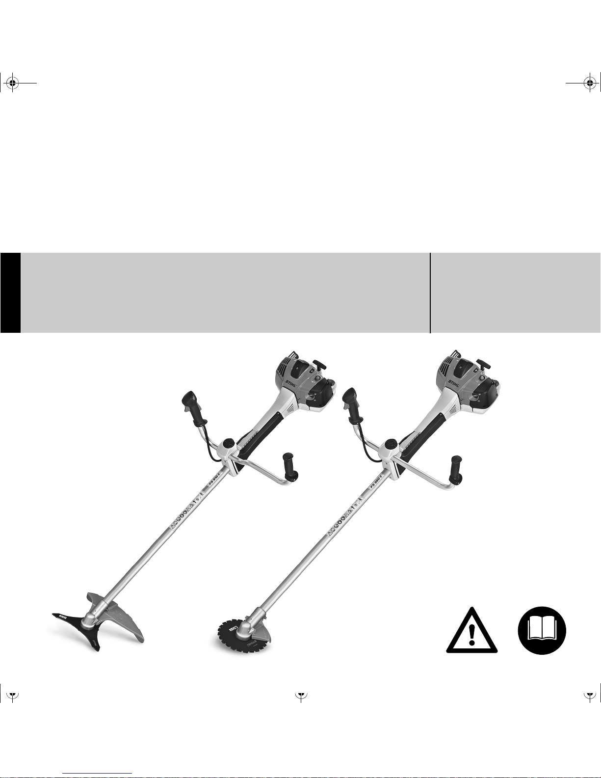
STIHL FS 510 C-M, 560 C-M
Instruction Manual
Notice d’emploi
Page 2

G Instruction Manual
1 - 54
F Notice d’emploi
55 - 114
Page 3

Original Instruction ManualPrinted on chlorine-free paper
Printing inks contain vegetable oils, paper can be recycled.
© ANDREAS STIHL AG & Co. KG, 2012
0458-772-8221-A. VA0.A12.
0000005287_001_GB
FS 510 C-M, FS 560 C-M
English
1
{
This instruction manual is protected by copyright. All rights reserved, especially the rights to reproduce, translate and process
with electronic systems.
Contents
Dear Customer,
Thank you for choosing a quality
engineered STIHL product.
This machine has been built using
modern production techniques and
comprehensive quality assurance.
Every effort has been made to ensure
your satisfaction and troublefree use of
the machine.
Please contact your dealer or our sales
company if you have any queries
concerning your machine.
Your
Hans Peter Stihl
Guide to Using this Manual 2
Safety Precautions and Working
Techniques 2
Approved Combinations of Cutting
Attachment, Deflector, Limit Stop
and Harness 12
Mounting the Bike Handle 13
Adjusting the Throttle Cable 17
Mounting the Deflector 17
Mounting the Cutting Attachment 21
Fuel 26
Fueling 27
Fitting the Full Harness 28
Balancing the Trimmer/Brushcutter 28
Starting / Stopping the Engine 29
Operating Instructions 32
Air filter 32
Engine Management 33
M-Tronic 33
Winter Operation 34
Spark Plug 35
Engine Running Behavior 36
Replacing the Starter Rope and
Rewind Spring 37
Storing the Machine 40
Sharpening Metal Cutting Blades 41
Replacing Nylon Line 41
Replacing the Cutting Blade 42
Inspection and Maintenance by
User 43
Inspections and Maintenance by
Dealer 44
Maintenance and Care 46
Main Parts 48
Specifications 50
Special Accessories 51
Maintenance and Repairs 52
STIHL Limited Emission Control
Warranty Statement 53
Page 4
FS 510 C-M, FS 560 C-M
English
2
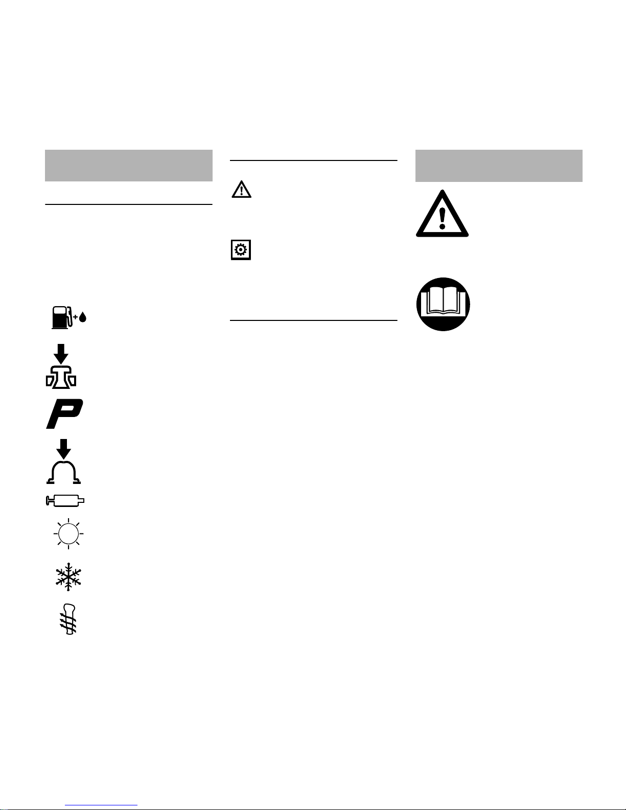
Pictograms
The meanings of the pictograms
attached to the machine are explained in
this manual.
Depending on the model concerned, the
following pictograms may be attached to
your machine.
Symbols in text
Warning where there is a risk of an
accident or personal injury or serious
damage to property.
Caution where there is a risk of
damaging the machine or its individual
components.
Engineering improvements
STIHL's philosophy is to continually
improve all of its products. For this
reason we may modify the design,
engineering and appearance of our
products periodically.
Therefore, some changes, modifications
and improvements may not be covered
in this manual.
Observe all application local safety
regulations, standards and ordinances.
If you have not used this type of power
tool before: Have your dealer or other
experienced user show you how to
operate your power tool or attend a
special course in its operation.
Minors should never be allowed to use a
power tool.
Keep bystanders, especially children,
and animals away from the work area.
When the power tool is not in use, shut it
off so that it does not endanger others.
Secure it against unauthorized use.
The user is responsible for avoiding
injury to third parties or damage to their
property.
Guide to Using this Manual
Fuel tank; fuel mixture of
gasoline and engine oil
Operate decompression
valve
Manual fuel pump
Operate manual fuel
pump
Tube of grease
Intake air: Summer
operation
Intake air: Winter
operation
Handle heating
Safety Precautions and
Working Techniques
Some special safety precautions have to be
observed when working
with this power tool
because of the very high
speed of the cutting
attachment.
It is important you read
and understand the
instruction manual before
first use and keep the
manual in a safe place for
future reference. Nonobservance of the
instruction manual may
result in serious or even
fatal injury.
Page 5
FS 510 C-M, FS 560 C-M
English
3
Do not lend or rent your power tool
without the instruction manual. Be sure
that anyone using it understands the
information contained in this manual.
The use of noise emitting power tools
may be restricted to certain times by
national or local regulations.
To operate the power tool you must be
rested, in good physical condition and
mental health.
If you have any condition that might be
aggravated by strenuous work, check
with your doctor before operating a
power tool.
Persons with pacemakers only: The
ignition system of your power tool
produces an electromagnetic field of a
very low intensity. This field may
interfere with some pacemakers. STIHL
recommends that persons with
pacemakers consult their physician and
the pacemaker manufacturer to reduce
any health risk.
Do not operate the power tool if you are
under the influence of any substance
(drugs, alcohol) which might impair
vision, dexterity or judgment.
Depending on the cutting attachment
fitted, use your power tool only for
cutting grass, wild growth, shrubs,
scrub, bushes, small diameter trees and
similar materials.
Do not use your power tool for any other
purpose because of the increased risk of
accidents.
Only use cutting attachments and
accessories that are explicity approved
for this power tool model by STIHL or
are technically identical. If you have any
questions in this respect, consult a
servicing dealer. Use only high quality
parts and accessories in order to avoid
the risk of accidents and damage to the
machine.
STIHL recommends the use of original
STIHL replacement parts. They are
specifically designed to match your
model and meet your performance
requirements.
Never attempt to modify your unit in any
way since this may increase the risk of
personal injury. STIHL excludes all
liability for personal injury and damage
to property caused while using
unauthorized attachments.
Do not use a pressure washer to clean
the power tool. The solid jet of water
may damage parts of the power tool.
The deflector on this power tool cannot
protect the operator from all objects
thrown by the cutting attachment
(stones, glass, wire, etc.). Such objects
may ricochet and then hit the operator.
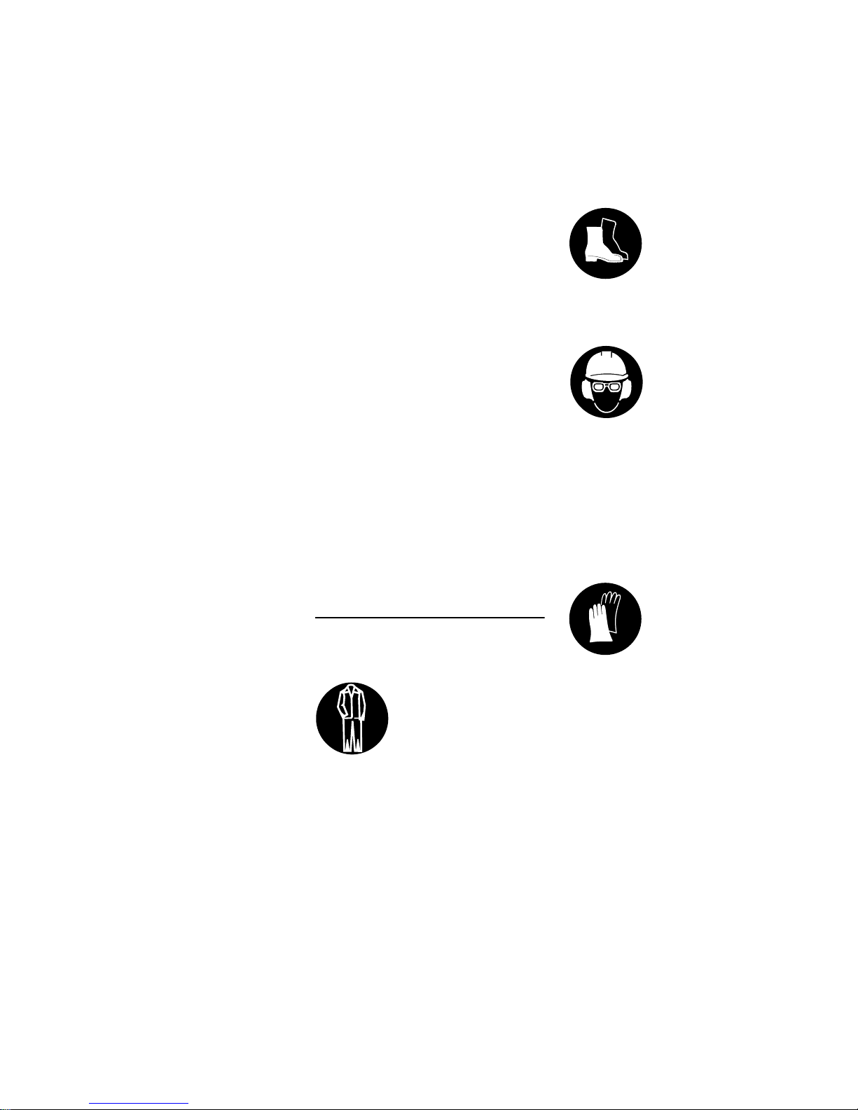
Clothing and Equipment
Wear proper protective clothing and
equipment.
Avoid clothing that could get caught on
branches or brush or moving parts of the
machine. Do not wear a scarf, necktie or
jewelry. Tie up and confine long hair
(e.g. with a hair net, cap, hard hat, etc.).
Sturdy shoes with non-slip soles may be
worn as an alternative only when using
mowing heads.
A face shield alone does not provide
adequate eye protection.
Wear hearing protection, e.g. earplugs
or ear muffs.
STIHL offers a comprehensive range of
personal protective clothing and
equipment.
Clothing must be sturdy
but allow complete freedom of movement. Wear
snug-fitting clothing, an
overall and jacket combination, do not wear a
work coat.
Wear steel-toed safety
boots with non-slip soles.
Wear a safety hard hat
for thinning operations,
when working in high
scrub and where there is
a danger of head injuries
from falling objects. To
reduce the risk of injury
from thrown objects,
always wear a face shield
and safety glasses.
Wear heavy-duty gloves.
Page 6
FS 510 C-M, FS 560 C-M
English
4
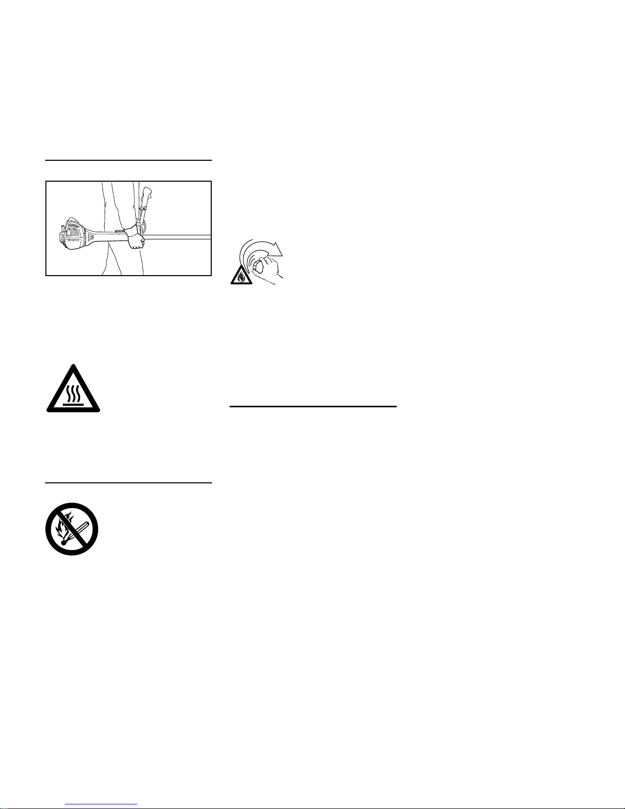
Transporting the Power Tool
Always stop the engine.
Carry the unit hanging from the shoulder
strap or properly balanced by the drive
tube. Fit transport guard on metal cutting
attachments to avoid the risk of injury
from blade contact
Transporting in a vehicle: Properly
secure your power tool to prevent
turnover, fuel spillage and damage.
Fueling
Always shut off the engine before
refueling.
Do not fuel a hot engine – fuel may spill
and cause a fire.
Open the fuel cap carefully to allow any
pressure build-up in the tank to release
slowly and avoid fuel spillage.
Fuel your power tool only in wellventilated areas. If you spill fuel, wipe
the machine immediately – if fuel gets on
your clothing, change immediately.
This reduces the risk of unit vibrations
causing the fuel cap to loosen or come
off and spill quantities of fuel.
To reduce the risk of serious or fatal
burn injuries, check for fuel leakage. If
fuel leakage is found, do not start or run
the engine until leak is fixed.
Before Starting
Check that your power tool is properly
assembled and in good condition – refer
to appropriate chapters in the instruction
manual.
– Use only an approved combination
of cutting attachment, deflector,
handle and harness. All parts must
be assembled properly and
securely.
– The stop switch must move freely.
– Smooth action of choke knob,
throttle trigger lockout and throttle
trigger – the throttle trigger must
return automatically to the idle
position. The choke knob must
spring back from the } position to
the run position F when the throttle
trigger lockout and throttle trigger
are squeezed.
– Check that the spark plug boot is
secure – a loose boot may cause
arcing that could ignite combustible
fumes and cause a fire.
– Cutting tool or attachment: Check
for correct and secure assembly
and good condition.
– Check protective devices (e.g.
deflector for cutting attachment,
rider plate) for damage or wear.
Always replace damaged parts. Do
not operate your machine with a
damaged deflector or worn rider
plate (lettering and arrows no longer
legible).
– Never attempt to modify the controls
or safety devices in any way.
– Keep the handles dry and clean –
free from oil and dirt – for safe
control of the power tool.
– Adjust the harness and handle(s) to
suit your height and reach. See
chapters on "Fitting the Harness"
and "Balancing the Machine".
To reduce the risk of personal injury, do
not operate your power tool if it is
damaged or not properly assembled.
If you use a shoulder strap or full
harness: Practice removing and putting
down the machine as you would in an
To reduce the risk of serious burn injuries, avoid
touching hot parts of the
machine, including the
gearbox housing.
Gasoline is an extremely
flammable fuel. Keep
clear of naked flames. Do
not spill any fuel – do not
smoke.
002BA479 KN
After fueling, tighten
down the screw-type fuel
cap as securely as
possible.
Page 7
FS 510 C-M, FS 560 C-M
English
5
emergency. To avoid damage, do not
throw the machine to the ground when
practicing.
Starting the Engine
Start the engine at least 3 meters from
the fueling spot, outdoors only.
Place the unit on firm ground in an open
area. Make sure you have good balance
and secure footing. Hold the unit
securely. The cutting attachment must
be clear of the ground and all other
obstructions because it may begin to run
when the engine starts.
Your power tool is a one-person unit. To
reduce the risk of injury from thrown
objects, do not allow other persons
within a radius of 15 meters of your own
position – even when starting.
To reduce the risk of fire, keep hot
exhaust gases and hot muffler away
from easily combustible materials (e.g.
wood chips, bark, dry grass, fuel).
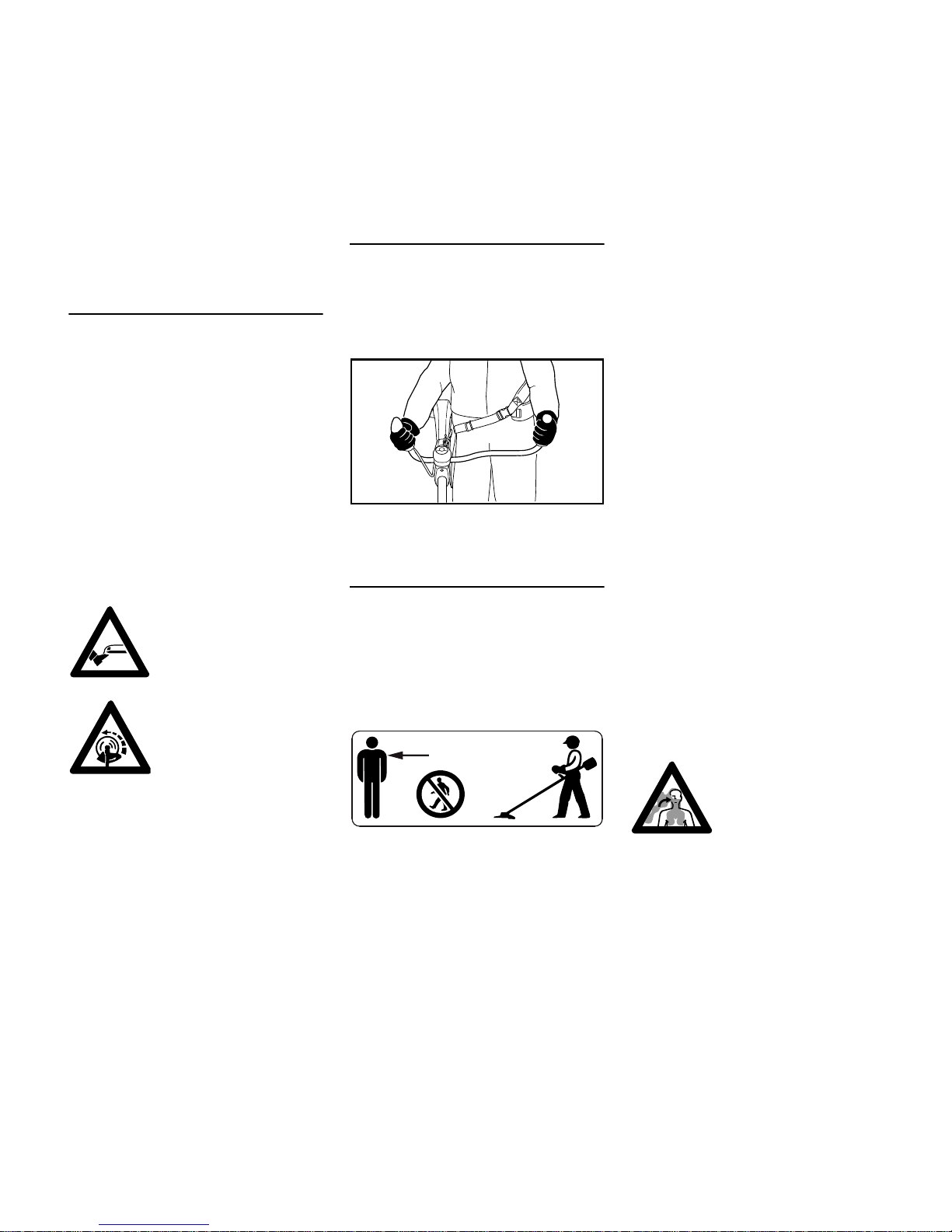
Holding and Controlling the Power Tool
Always hold the power tool firmly with
both hands on the handles.
Make sure you always have good
balance and secure footing.
Right handle on control handle, left hand
on left handle.
During Operation
Make sure you always have good
balance and secure footing.
In the event of imminent danger or in an
emergency, press the stop switch to
shut off the engine.
To reduce the risk of injury, do not allow
any other persons within a radius of 15
meters of your own position. To reduce
the risk of damage to property, also
maintain this distance from other objects
(vehicles, windows).
The correct engine idle speed is
important to ensure that the cutting
attachment stops rotating when you let
go of the throttle trigger. If the cutting
attachment continues to rotate when the
engine is idling, have the machine
checked by your servicing dealer. STIHL
recommends a STIHL servicing dealer.
Take special care in slippery conditions
– damp, snow, ice, on slopes or uneven
ground.
Watch out for obstacles: Roots, tree
stumps or holes which could cause you
to trip or stumble.
Always stand on the ground while
working, never on a ladder, work
platform or any other insecure support.
Be particularly alert and cautious when
wearing hearing protection because
your ability to hear warnings (shouts,
alarms, etc.) is restricted.
To reduce the risk of accidents, take a
break in good time to avoid tiredness or
exhaustion.
Work calmly and carefully – in daylight
conditions and only when visibility is
good. Stay alert so as not to endanger
others.
To reduce the risk of
injury, avoid contact with
the cutting attachment.
Do not drop start the
power tool – start the
engine as described in
the instruction manual.
Note that the cutting
attachment continues to
run for a short period
after you let go of the
throttle trigger – flywheel
effect.
002BA480 KN
15m (50ft)
Your power tool produces
toxic exhaust fumes as
soon as the engine is
running. These fumes
may be colorless and
odorless and contain
unburned hydrocarbons
and benzol. Never run
the engine indoors or in
poorly ventilated locations, even if your model
is equipped with a catalytic converter.
Page 8
FS 510 C-M, FS 560 C-M
English
6
To reduce the risk of serious or fatal
injury from breathing toxic fumes,
ensure proper ventilation when working
in trenches, hollows or other confined
locations.
To reduce the risk of accidents, stop
work immediately in the event of
nausea, headache, visual disturbances
(e.g. reduced field of vision), problems
with hearing, dizziness, deterioration in
ability to concentrate. Apart from other
possibilities, these symptoms may be
caused by an excessively high
concentration of exhaust gases in the
work area.
Operate your power tool so that it
produces a minimum of noise and
emissions – do not run the engine
unnecessarily, accelerate the engine
only when working.
To reduce the risk of fire, do not smoke
while operating or standing near your
power tool. Note that combustible fuel
vapor may escape from the fuel system.
The dusts, vapor and smoke produced
during operation may be dangerous to
health. If the work area is very dusty or
smoky, wear a respirator.
If your power tool is subjected to
unusually high loads for which it was not
designed (e.g. heavy impact or a fall),
always check that it is in good condition
before continuing work – see also
"Before Starting".
Check the fuel system in particular for
leaks and make sure the safety devices
are working properly. Do not continue
operating your power tool if it is
damaged. In case of doubt, have the unit
checked by your servicing dealer.
Special care must be taken when
working in difficult, over-grown terrain.
When cutting high scrub, under bushes
and hedges: Keep cutting attachment at
minimum height of 15 cm to avoid
harming small animals.
Always shut off the engine before
leaving the unit unattended.
Check the cutting attachment at regular
short intervals during operation or
immediately if there is a noticeable
change in cutting behavior:
– Turn off the engine. Hold the unit
firmly and wait for the cutting
attachment to come to a standstill.
– Check condition and tightness, look
for cracks.
– Check sharpness.
– Replace damaged or dull cutting
attachments immediately, even if
they have only superficial cracks.
Clean grass and plant residue off the
cutting attachment mounting at regular
intervals – remove any build up of
material from the cutting attachment and
deflector.
To reduce the risk of injury, shut off the
engine before replacing the cutting
attachment.
Do not continue using or attempt to
repair damaged or cracked cutting
attachments by welding, straightening or
modifying the shape (out of balance).
This may cause parts of the cutting
attachment to come off and hit the
operator or bystanders at high speed
and result in serious or fatal injuries
.
When using mowing heads
Use only the deflector with properly
mounted line limiting blade to ensure the
mowing lines are automatically trimmed
to the approved length.
To reduce the risk of injury, always turn
off the engine before adjusting the nylon
line of manually adjustable mowing
heads
Using the unit with over-long nylon
cutting lines reduces the motor's
operating speed. The clutch then slips
continuously and this causes
overheating and damage to important
components (e.g. clutch, polymer
housing components) – and this can
To reduce the risk
of injury from
thrown objects,
never operate the
unit without the
proper deflector for
the type of cutting
attachment being
used.
Inspect the work area:
Stones, pieces of metal
or other solid objects can
be thrown and cause personal injury or damage
the cutting attachment
and property (e.g. parked
vehicles, windows).
The gearbox becomes
hot during operation. To
reduce the risk of burn
injury, do not touch the
gearbox housing.
Page 9

FS 510 C-M, FS 560 C-M
English
7
increase the risk of injury from the
cutting attachment rotating while the
engine is idling.
When using metal cutting attachments
STIHL recommends the use of original
STIHL metal cutting attachments. They
are specifically designed to match your
model and meet your performance
requirements.
Metal cutting attachments rotate at very
high speed. The forces that occur act on
the machine, the attachment and the
material being cut.
Sharpen metal cutting attachments
regularly as specified.
Unevenly sharpened metal cutting
attachments cause out-of-balance
which can impose extremely high loads
on the machine and increase the risk of
breakage.
Dull or improperly sharpened cutting
edges can put a higher load on the
cutting attachment and increase the risk
of injury from cracked or broken parts.
Inspect metal cutting attachments for
cracks or warping after every contact
with hard objects (e.g. stones, rocks,
pieces of metal). To reduce the risk of
injury, remove burrs and other visible
build-ups of material (use a file) because
they may become detached and be
thrown at high speed during operation.
To reduce the above-mentioned risks
when using a metal cutting attachment,
never use a metal cutting attachment
with a diameter larger than specified. It
must not be too heavy. It must be
manufactured from materials of
adequate quality and its geometry must
be correct (shape, thickness).
To reduce the risk of injury, a metal
cutting attachment not manufactured by
STIHL must not be heavier, thicker,
have a different shape or a diameter
larger than the largest metal cutting
attachment approved by STIHL for this
power tool model.
Vibrations
Prolonged use of the power tool may
result in vibration-induced circulation
problems in the hands (whitefinger
disease).
No general recommendation can be
given for the length of usage because it
depends on several factors.
The period of usage is prolonged by:
– Hand protection (wearing warm
gloves)
– Work breaks
The period of usage is shortened by:
– Any personal tendency to suffer
from poor circulation (symptoms:
frequently cold fingers, tingling
sensations).
– Low outside temperatures.
– The force with which the handles
are held (a tight grip restricts
circulation).
Continual and regular users should
monitor closely the condition of their
hands and fingers. If any of the above
symptoms appear (e.g. tingling
sensation in fingers), seek medical
advice.
Maintenance and Repairs
Service the machine regularly. Do not
attempt any maintenance or repair work
not described in the instruction manual.
Have all other work performed by a
servicing dealer.
STIHL recommends that you have
servicing and repair work carried out
exclusively by an authorized STIHL
servicing dealer. STIHL dealers are
regularly given the opportunity to attend
training courses and are supplied with
the necessary technical information.
Only use high-quality replacement parts
in order to avoid the risk of accidents
and damage to the machine. If you have
any questions in this respect, consult a
servicing dealer.
STIHL recommends the use of original
STIHL replacement parts. They are
specifically designed to match your
model and meet your performance
requirements.
To reduce the risk of injury from
unintentional engine startup, always
shut off the engine and disconnect the
spark plug boot before performing any
repairs, maintenance or cleaning work. –
Exception: Carburetor and idle speed
adjustments.
Do not turn the engine over on the
starter with the spark plug boot or spark
plug removed since there is otherwise a
risk of fire from uncontained sparking.
To reduce the risk of fire, do not service
or store your machine near open flames.
Check the fuel filler cap for leaks at
regular intervals.
Page 10
FS 510 C-M, FS 560 C-M
English
8
Use only a spark plug of the type
approved by STIHL and make sure it is
in good condition – see "Specifications".
Inspect the ignition lead (insulation in
good condition, secure connection).
Check the condition of the muffler.
To reduce the risk of fire and damage to
hearing, do not operate your machine if
the muffler is damaged or missing. –
Do not touch a hot muffler since burn
injury will result.
Vibration behavior is influenced by the
condition of the AV elements – check the
AV elements at regular intervals.
Maintenance, replacement, or repair of
the emission control devices and
systems may be performed by any
nonroad engine repair establishment or
individual. However, if you make a
warranty claim for a component which
has not been serviced or maintained
properly or if nonapproved replacement
parts were used, STIHL may deny
coverage.
For any maintenance please refer to the
maintenance chart and to the warranty
statement near the end of the instruction
manual.
Symbols on Deflectors
An arrow on the deflector shows the
correct direction of rotation of the cutting
attachments.
Some of the following symbols are
applied to the outside of the deflector to
indicate the approved combination of
cutting attachment and deflector.
Harness
The harness is included with the
machine or available as a special
accessory.
N Use the harness.
N With the engine running, attach the
machine to the harness.
All cutting attachments must be used in
combination with a full harness with a
quick-release system.
Deflector may be used
with mowing heads.
Deflector may be used
with grass cutting blades.
Deflector may be used
with brush knives.
Deflector may be used
with shredder blades.
Deflector must not be
used with mowing heads.
Deflector must not be
used with grass cutting
blades.
Deflector must not be
used with brush knives.
Deflector must not be
used with shredder
blades.
Deflector must not be
used with circular saw
blades.
002BA397 KN
Page 11
FS 510 C-M, FS 560 C-M
English
9
Mowing Head with Nylon Lines
Nylon line achieves a soft cut for edging
and trimming around trees, fence posts,
etc. – less risk of damaging tree bark.
To reduce the risk of injury, never use
steel wire in place of the nylon cutting
line.
STIHL Polycut Mowing Head with
Polymer Blades
For mowing unobstructed edges of
meadows (without posts, fences, trees
or similar obstacles).
Check the wear limit marks!
If one of the wear limit marks on the
PolyCut mowing head is worn through
(arrow): Do not continue using the
mowing head. Install a new one. There
is otherwise a risk of injury from thrown
parts of the head.
It is important to follow the maintenance
instructions for the Polycut mowing
head.
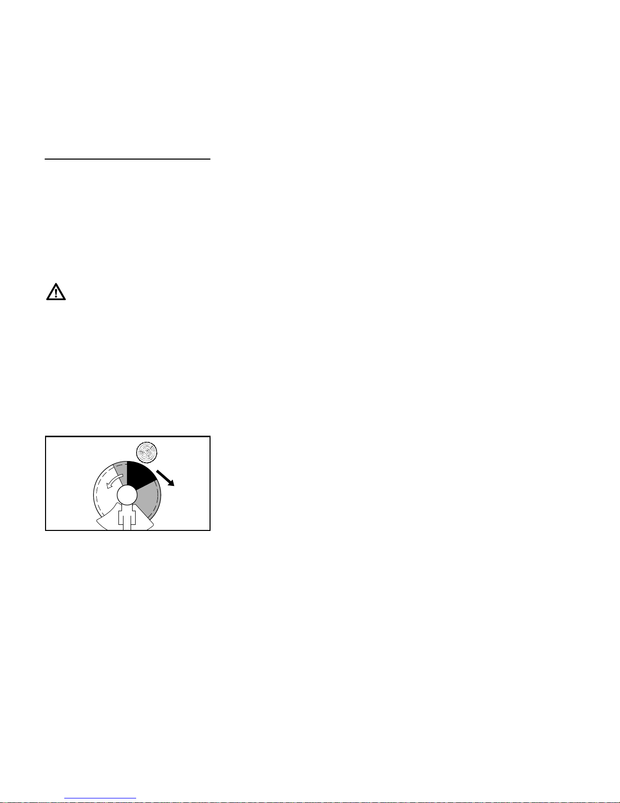
Risk of Kickout (Blade Thrust) with Metal
Cutting Attachments
When using metal cutting attachments
(grass cutting blade, brush knife,
shredder blade, circular saw blade)
there is a risk of kickout when the
rotating blade comes into contact with a
solid object such as a tree trunk, branch,
tree stump, rock or similar. The machine
is thrown to the right or to the rear –
opposite to the attachment's direction of
rotation.
The risk of kickout is greatest when the
black area of the rotating cutting
attachment comes into contact with a
solid object.
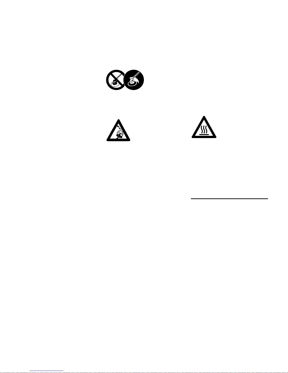
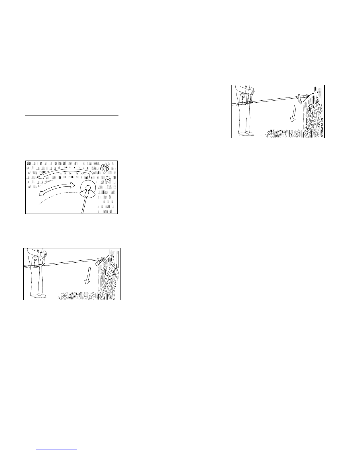
Grass Cutting Blade
Use for grass and weeds only – sweep
the brushcutter in an arc like a scythe.
Improper use may damage the grass
cutting blade – risk of injury from thrown
parts.
000BA015 KN
002BA396 KN
002BA135 KN
000BA020 KN
Page 12
FS 510 C-M, FS 560 C-M
English
10
Resharpen the grass cutting blade
according to instructions when it has
dulled noticeably.
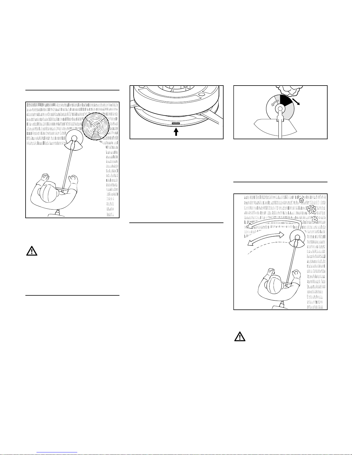
Brush Knife
For cutting matted grass, wild growth
and scrub and thinning young stands
with a stem diameter of no more than 2
cm – do not cut thicker stems – risk of
accidents.
Use the brushcutter like a scythe (sweep
it to the right and left) at ground level
when cutting grass and thinning young
stands.
To cut wild growth and scrub, lower the
brush knife down onto the growth to
achieve a shredding effect – always
keep the cutting attachment below hip
level during this process.
Exercise extreme caution when using
this method of cutting. The higher the
cutting attachment is off the ground, the
greater the risk of injury from cuttings
being thrown sideways.
Warning! Improper use of a brush knife
may cause it to crack, chip or shatter –
risk of injury from thrown parts.
To reduce the risk of injury it is essential
to take the following precautions:
– Avoid contact with stones, rocks,
pieces of metal and other solid
foreign objects.
– Never cut wood or shrubs with a
stem diameter of more than 2 cm –
use a circular saw blade for such
work.
– Inspect the brush knife at regular
short intervals for signs of damage.
Do not continue working with a
damaged brush knife.
– Resharpen the brush knife regularly
and whenever it has dulled
noticeably, and have it balanced if
necessary (STIHL recommends a
STIHL servicing dealer).
Shredder Blade
Suitable for thinning and shredding
tough, matted grass and scrub.
To cut wild growth and scrub, lower the
shredder blade down onto the growth to
achieve a shredding effect – always
keep the cutting attachment below hip
level during this process.
Exercise extreme caution when using
this method of cutting. The higher the
cutting attachment is off the ground, the
greater the risk of injury from cuttings
being thrown sideways.
Warning! Improper use may damage the
shredder blade – risk of injury from
thrown parts.
To reduce the risk of injury it is essential
to take the following precautions:
– Avoid contact with stones, rocks,
pieces of metal and other solid
foreign objects.
– Never cut wood or shrubs with a
stem diameter of more than 2 cm –
use a circular saw blade for such
work.
– Inspect the shredder blade at
regular short intervals for signs of
damage. Do not continue working
with a damaged shredder blade.
– Resharpen the shredder blade
regularly and whenever it has dulled
noticeably, and have it balanced if
necessary (STIHL recommends a
STIHL servicing dealer).
002BA355 KN
002BA509 KN
Page 13
FS 510 C-M, FS 560 C-M
English
11
Circular Saw Blade
Suitable for cutting shrubs and trees with
a maximum stem diameter of 7 cm.
Before starting the cut, accelerate the
engine up to full throttle. Perform cut
with uniform pressure.
Use circular saw blades only with a
matching limit stop of the correct
diameter.
To reduce the risk of blade damage,
avoid contact with stones and the
ground. Resharpen the blade properly in
good time – dull teeth may result in the
blade cracking and shattering and
causing serious injury.
When felling, maintain a distance of at
least two tree lengths from the next
felling site.
Risk of kickout
The risk of kickout is highest in the black
area of the blade: Do not use this area of
the circular saw blade for cutting.
There is also a risk of kickout when
using the lighter shaded areas of the
blade: These areas of the blade should
only be used by experienced operators
with specialized training.
STIHL recommends that you use the
non-shaded area of the circular saw
blade. Always start the cut with this area
of the blade.
002BA449 KN
Page 14
FS 510 C-M, FS 560 C-M
English
12
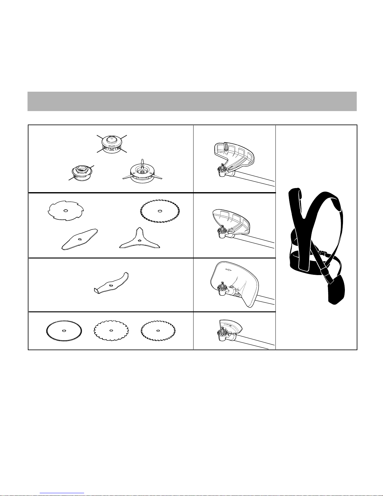
Approved Combinations of Cutting Attachment, Deflector, Limit Stop and Harness
Cutting Attachment Deflector, Limit Stop Harness
5
7
681BA183 KN
3
6
8
4
12
13
14
16
2
9
10
11
15
1
Page 15
FS 510 C-M, FS 560 C-M
English
13
Approved Combinations
Select correct combination from the
table according to the cutting
attachment you intend to use.
For safety reasons only the cutting
attachments and deflectors or limit stops
shown in each row of the table may be
used together. No other combinations
are permitted because of the risk of
accidents.
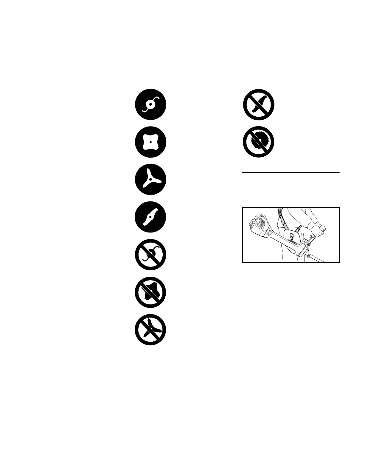
Cutting Attachments
Mowing heads
1 STIHL AutoCut 40-4
2 STIHL TrimCut 51-2
3 STIHL PolyCut 41-3
Metal cutting attachments
4 Grass cutting blade 255-8
5 Grass cutting blade 250-40 Spezial
6 Brush knife 305-2 Spezial
7 Brush knife 350-3
8 Shredder blade 320-2
9 Scratcher tooth circular saw blade
225
10 Chisel tooth circular saw blade 225
11 Carbide tipped circular saw blade
225
Non-metal grass cutting blades, brush
knives, shredder blades and circular
saw blades are not approved.
Deflectors, Limit Stops
Deflectors
12 Deflector for mowing heads only
13 Deflector for metal mowing
attachments, items 4 to 7
14 Deflector for shredder blade
Limit stops
15 Limit stop for circular saw blades
225
Harnesses
16 Full harness must be used
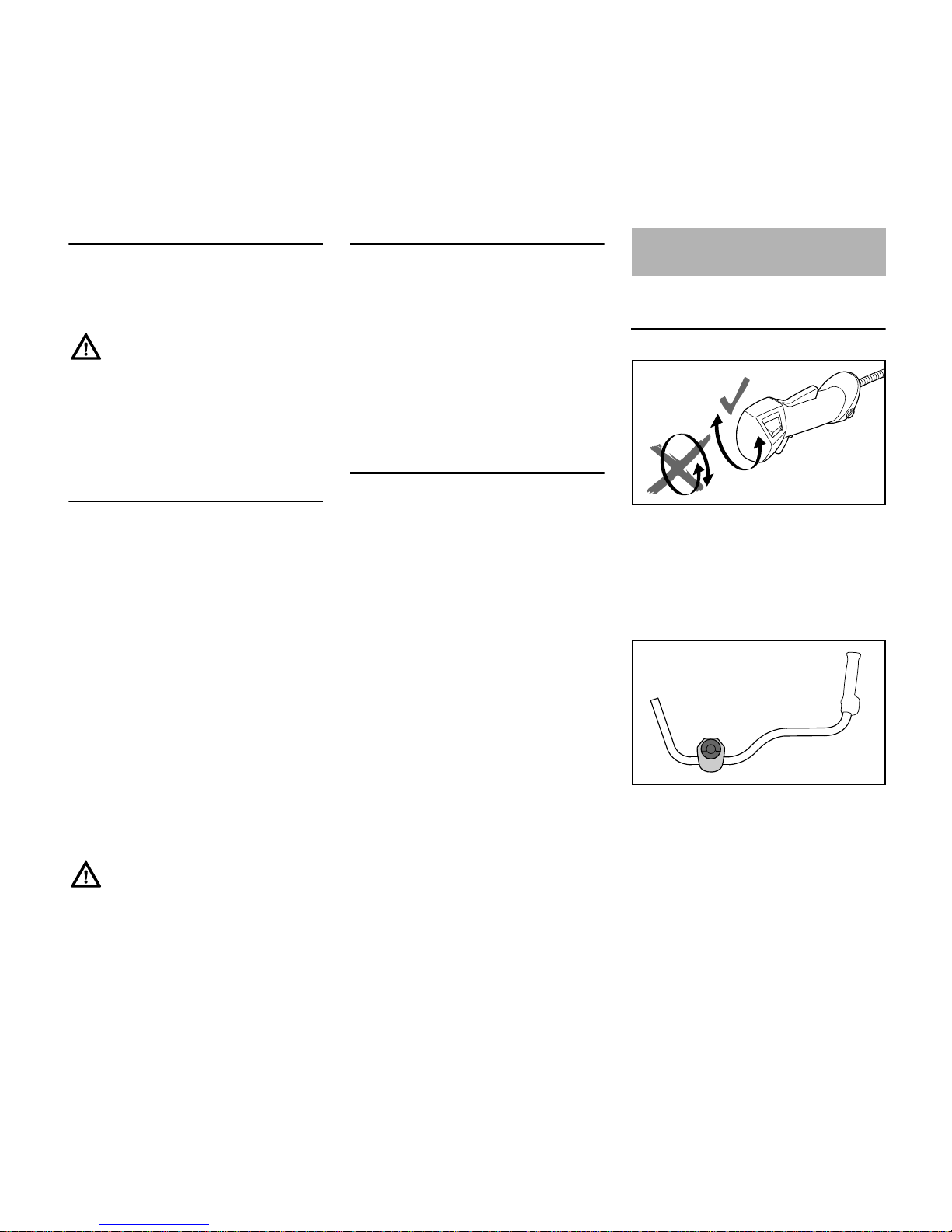
Mounting Bike Handle with Swiveling
Handle Support
Do not rotate the control handle (1)
between unpacking and mounting it on
the handlebar; see also chapter on
"Adjusting the Throttle Cable".
The brushcutter is available with two
different handlebars:
2 Handlebar for machines used
primarily for mowing, brushcutting
and shredding, but also for
occasional sawing.
Mounting the Bike Handle
1
3BA003 KN
3BA004 KN
4
2
Page 16
FS 510 C-M, FS 560 C-M
English
14
3 Handlebar for machines used
mainly for sawing, but also for
mowing and brushcutting.
The machine is supplied with the clamp
moldings (4) mounted on the handlebars
(2, 3).
N Do not change the position of the
clamp moldings on the handlebar
until it is mounted on the handle
support.
The mounting procedure is the same for
both types of handlebar. Therefore, the
following description only shows
handlebar (2).
Mounting the Handlebar
Assembly of the swivelling handle
support involves equipping the clamp
moldings with a spring and mounting
them on the handle support.
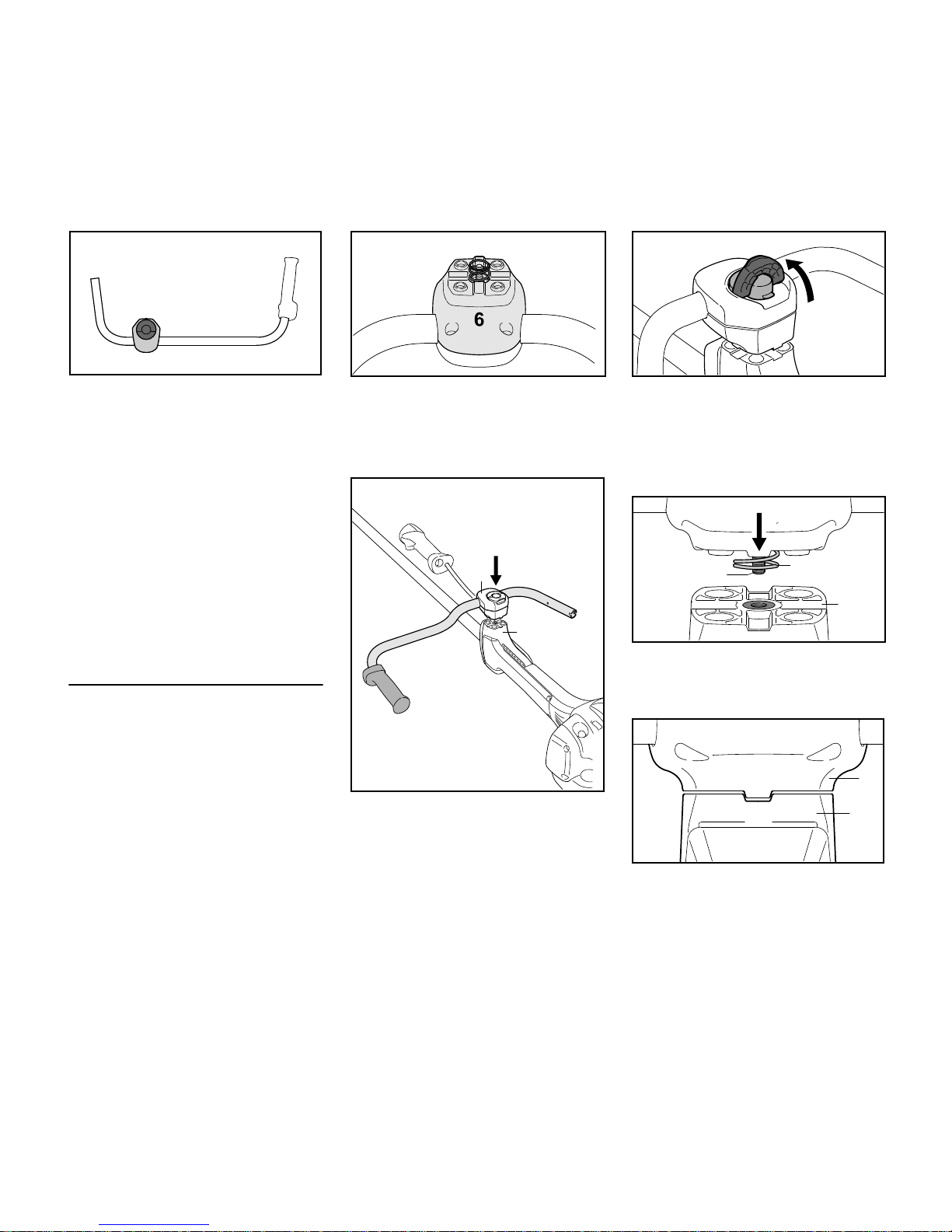
N Use the spring (5) from the parts kit
supplied with the machine.
N Push the spring (5) into the lower
clamp molding (6).
N Position the clamp moldings (4) with
handlebar (2) on the handle support
(7).
N Do not turn the handlebar in the
clamp moldings.
N Raise the grip of the wing screw (8)
to the upright position.
N Rotate the wing screw
counterclockwise and tighten it only
moderately.
N Position wing screw (8) in threaded
insert in handle support (7) – against
pressure of spring (5).
N Position the clamp moldings so that
the tabs (9) on the lower clamp
molding (6) line up with the slots
(10) in the handle support (7).
2BA001 KN
4
3
3BA005 KN
5
4900BA002 KN
7
2
4
8
3BA007 KN
5
8
3BA008 KN
7
6
10
7
9
3BA0009 KN
Page 17
FS 510 C-M, FS 560 C-M
English
15
N Rotate wing screw clockwise until
the lower clamp molding (6) butts
against the handle support (7).
N Swing the handebar (2) forwards
through 180°.
N Only tighten the wing screw
moderately.
N Fold the grip of the wing screw down
so that it is flush.
Mounting the Control Handle
N Take out the screw (11) and remove
the nut (12) from the control handle
(1).
N Hold the control handle in front of
the right-hand end of the handlebar
so that the throttle cable (13) is on
the inboard side of the handlebar
(2).
N Push the control handle (1) in this
position onto the end of the
handlebar (2) until the holes (15)
line up – throttle trigger (14) facing
down.
N Fit the nut (12) in the control handle,
insert the screw (11) and tighten it
down firmly.
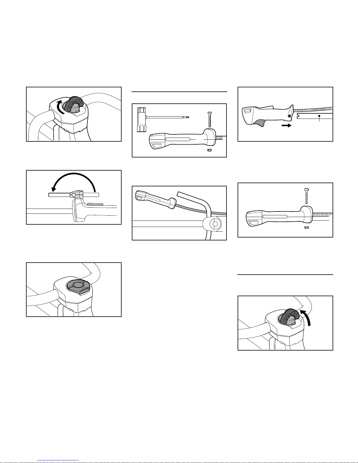
Adjusting the Handlebar
Opening the wing screw
N Raise the grip of the wing screw to
the upright position.
7
6
3BA010 KN
2
4900BA003 KN
4900BA004 KN
11
12
1
002BA451 KN
13
2
4900BA005 KN
14
15
15
2
4900BA007 KN
1
11
12
4900BA008 KN
4900BA009 KN
Page 18
FS 510 C-M, FS 560 C-M
English
16
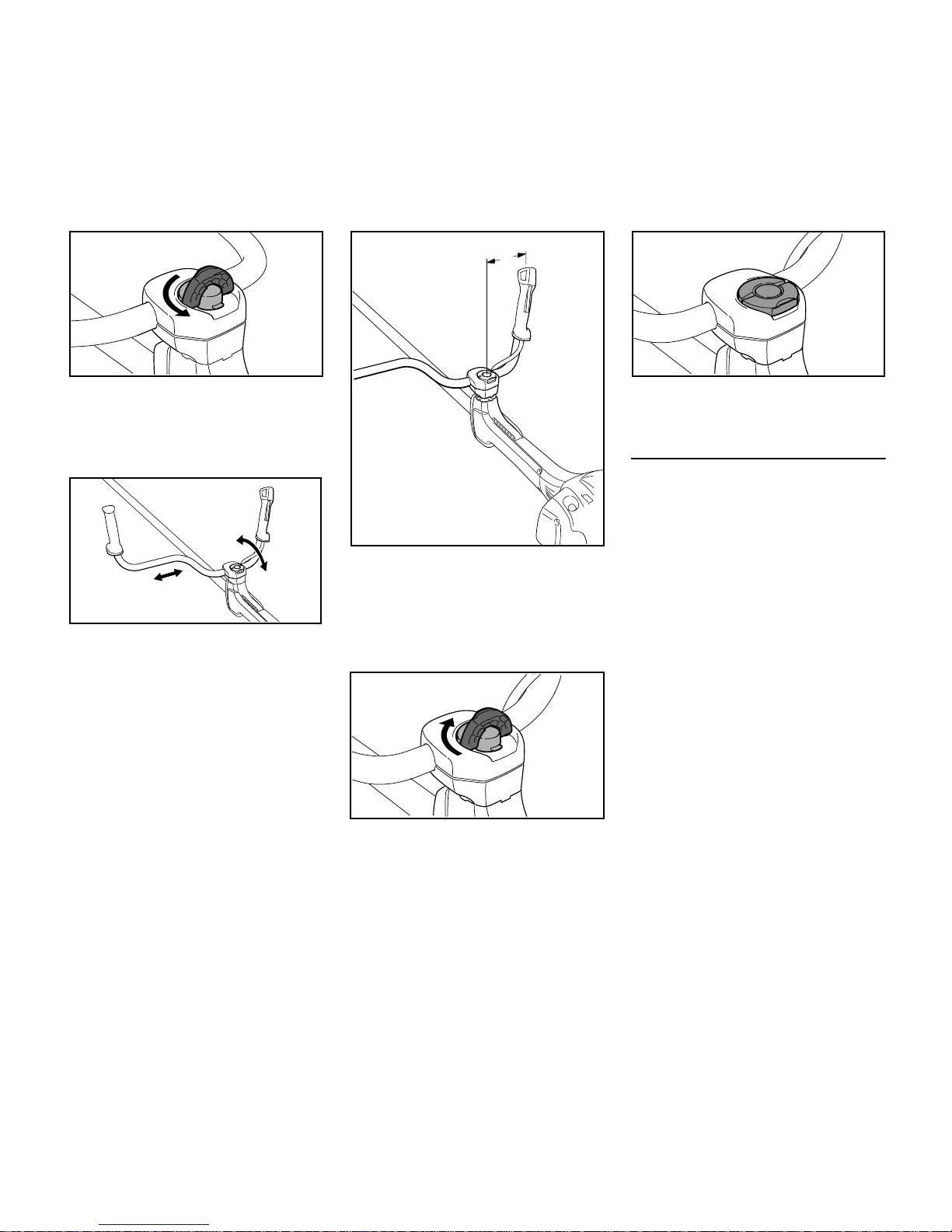
N Turn the wing screw
counterclockwise until the handle
support can be moved.
Lining up the handlebar
N Move the handlebar to the required
position.
N Position the handlebar (2) so that
distance A is about 7 in (17 cm).
Do not clamp the curved part of the
handlebar.
Closing the wing screw
N Rotate the wing screw clockwise
until it becomes difficult to turn.
N Tighten down the wing screw firmly.
N Fold the grip of the wing screw down
so that it is flush.
Checking the Throttle Cable
N After mounting the control handle,
check the throttle cable – see
chapter on "Adjusting the Throttle
Cable".
4900BA010 KN
4900BA011 KN
4900BA012 KN
2
A
4900BA013 KN
4900BA014 KN
Page 19
FS 510 C-M, FS 560 C-M
English
17
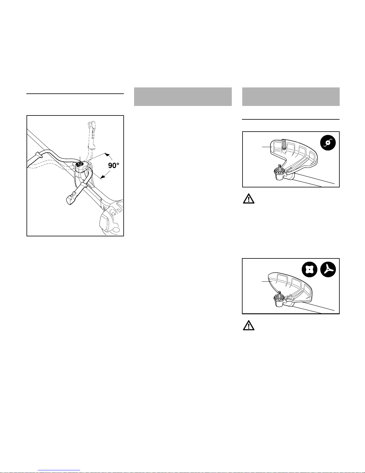
Swiveling the Handlebar
Transport position
N Loosen the wing screw (8) and
unscrew it until the handlebar (2)
can be turned clockwise.
N Turn the handlebar 90° and then
swing the handles down.
N Tighten down the wing screw (8)
firmly.
Working position
N Reverse the sequence described
above to swing the handles up and
turn the handlebar
counterclockwise.
Correct adjustment of the throttle cable
is a preconditon for correct operation of
the machine in all modes, from starting
to full throttle.
It may be necessary to readjust the
throttle cable after assembling the
machine or after a prolonged period of
operation.
– The throttle cable can checked and
adjusted by the user: see
"Inspection and Maintenance by
User".
– The throttle cable can be checked
and adjusted by your dealer. Have
the machine repaired by your
servicing dealer. STIHL
recommends a STIHL servicing
dealer.
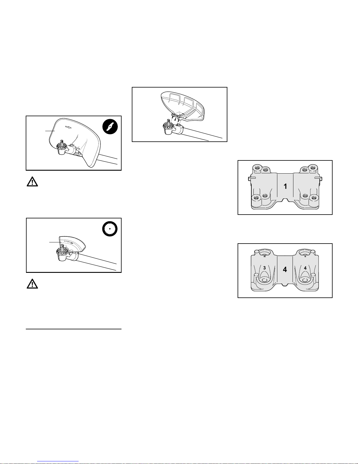
Use the Right Deflector
Deflector (1) is approved for mowing
heads only and must therefore be
mounted before fitting a mowing head.
Recommendation: Use mowing heads
with a grass shield on the gearbox, see
chapters on "Mounting the Deflector" /
"Mounting the Grass Shield".
Deflector (2) is approved for grass
cutting blades and brush knives only and
must therefore be mounted before fitting
a grass cutting blade or brush knife.
4900BA015 KN
2
8
Adjusting the Throttle Cable Mounting the Deflector
1
002BA461 KN
2
002BA462 KN
Page 20
FS 510 C-M, FS 560 C-M
English
18
Recommendation: Use grass cutting
blades with a grass shield on the
gearbox, see chapters on "Mounting the
Deflector" / "Mounting the Grass Shield".
Deflector (3) is approved for shredder
blades only and must therefore be
mounted before fitting a shredder blade,
see chapter on "Mounting the Deflector".
Stop (4) is approved for circular saw
blades only and must therefore be
mounted before fitting a circular saw
blade.
Mounting the Deflector
Deflectors (1, 2 and 4) are mounted to
the gearbox in the same way.
N Remove dirt from joints on gearbox
and deflector – make sure that no
dirt gets into the screw holes in the
gearbox – see section on "Plugs".
N Place the deflector on the gearbox
(5).
N Insert the screws (6) and tighten
them down firmly.
Mounting shredder deflector
Owing to the high loads on the shredder
deflector (3) and country-specific
regulations on the use of the machine for
shredding, the deflector must be
properly mounted to the machine.
A special screwdriver bit is required to
mount this deflector. The bit is available
only from specialist retailers. It has a
special drive for rotating the screws and
only allows the screws to be tightened.
Once tightened, the screws can no
longer be loosened – not even with the
special tool.
STIHL therefore recommends: Have the
shredder deflector mounted by your
STIHL dealer.
A "shredder deflector mounting kit" is
available as a special accessory for
retrofitting machines with a shredder
deflector. Depending on the machine's
original equipment, a "shredder blade
retrofit kit" may also be needed for the
conversion. Neither of these kits include
the shredder blade – it must be ordered
separately.
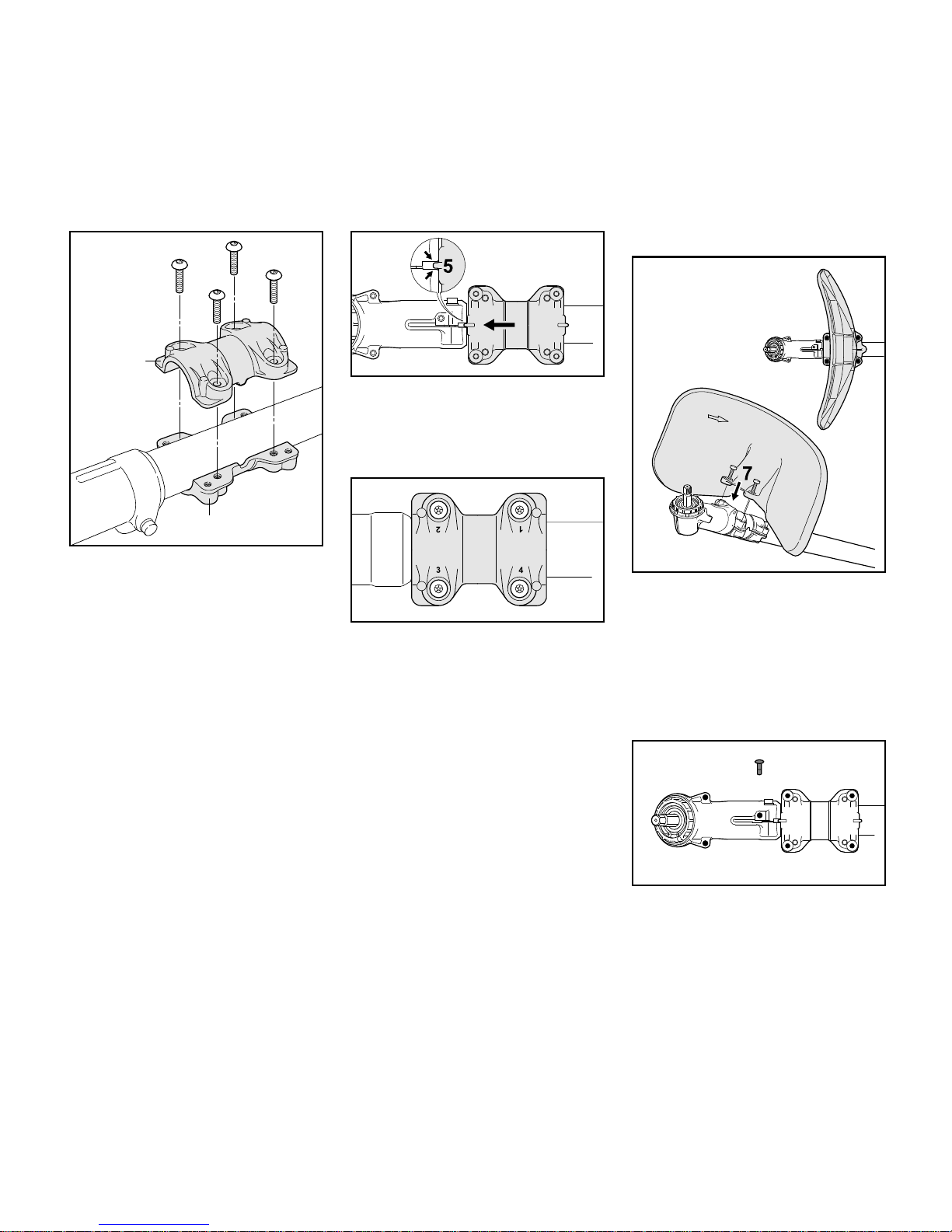
The "shredder blade retrofit kit" contains
clamps which butt against the gearbox
and have to be secured to the drive tube.
The kit also contains the shredder
deflector which is mounted to the
clamps.
– Installing the clamps
– Lower clamp (1): Identified by two
lugs (2) on its longitudinal axis, eight
tapped holes and a lateral notch (3).
– Upper clamp (4): Identified by holes
marked 1 to 4 and a lateral lug (5).
3
002BA463 KN
4
002BA464 KN
5
6
002BA465 KN
002BA495 KN
3
2
2
002BA496 KN
5
Page 21
FS 510 C-M, FS 560 C-M
English
19
N Position the lower clamp (1) against
the underside of the drive tube next
to the gearbox.
N Position the upper clamp (4) on the
drive tube so that the lug (5)
engages the notch (3).
N Hold both clamps steady in this
position.
N Insert a screw into the hole marked
1 on the upper clamp (4) and wind it
only a few turns into the lower clamp
(1).
N Insert a screw in each of the holes
marked 2, 3 and 4 and wind them
only a few turns into the lower
clamp.
N Slide the clamps up against the
gearbox and engage the lug (5) in
the gearbox gap (arrows).
N Hold both clamps in this position.
N Screw home the screws in holes 1
and 2 as far as stop.
N Tighten down the screws in holes 1
and 2 to a torque of 8 Nm.
N Screw home the screws in holes 3
and 4 in that order and tighten them
down to a torque of 8 Nm.
– Mounting the shredder deflector
N Position the shredder deflector on
the lower clamp with its concave
side facing the gearbox (6).
N Insert the screws (7) and tighten
them down firmly.
– Plugs
Plugs (9) are available as special
accessories to help prevent dirt getting
into the unused tapped holes for the
deflector in the gearbox (6) and clamps
(8).
5
3
002BA497 KN
1
4
002BA498 KN
002BA499 KN
6
002BA500 KN
002BA466 KN
8
9
6
Page 22
FS 510 C-M, FS 560 C-M
English
20
Four plugs (9) are supplied with the
shredder deflector.
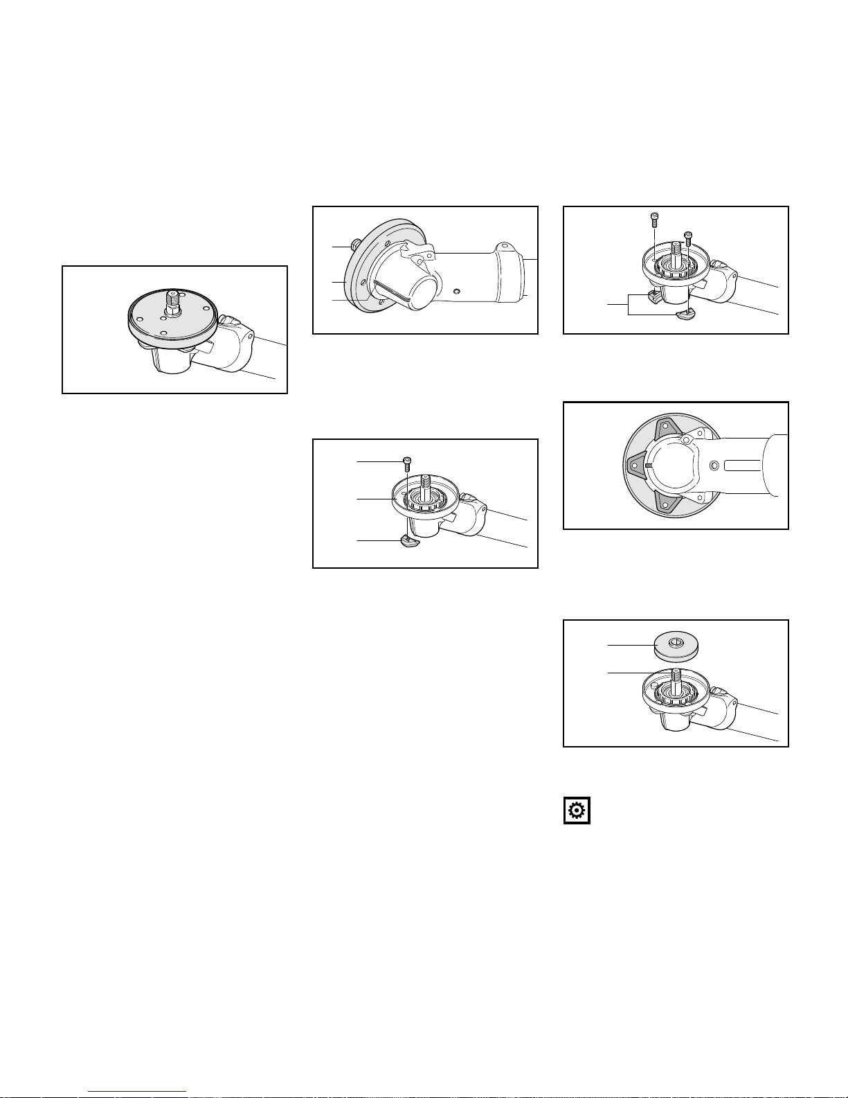
Fitting the grass shield
A grass shield is mounted to the gearbox
when using mowing heads and grass
cutting blades. It greatly reduces the
amount of grass, plant residue, etc. that
wraps itself around the gearbox and
cutting attachment.
Machines which have a mowing head or
grass cutting blade as original
equipment are supplied with a grass
shield. A "grass shield kit" is available as
a special accessory for retrofitting to
machines.
N Install the grass shield before
mounting the deflector – if
necessary, remove the deflector
that is already fitted on the gearbox.
N Hold the gearbox so that the shaft
(1) faces up.
N Place the grass shield (2) on the
gearbox so that the middle hole is in
line with the rib (3).
N Hold one of the three retainers (4)
against the gearbox and grass
shield so that the hole in the retainer
lines up with the middle hole.
N Insert the screw (5) in the retainer
and tighten it down only moderately
so that the grass shield (2) can still
be rotated on the gearbox.
N Fit the other two retainers (4) on the
gearbox and tighten down the
screws only moderately.
N Align the grass shield so that the
center of the front retainer is in line
with the rib on the gearbox.
N Tighten down the screws firmly.
N Fit the 60-mm diameter thrust plate
(5) on the shaft (1).
Only use the 60-mm diameter thrust
plate. The 65-mm diameter thrust plate
is too big and must not be used – see
002BA501 KN
002BA502 KN
1
2
3
002BA503 KN
4
2
5
002BA504 KN
4
002BA512 KN
002BA505 KN
5
1
Page 23
FS 510 C-M, FS 560 C-M
English
21
chapters "Mounting the Cutting
Attachment" / "Mounting the Mowing
Head" / "Mounting Grass Cutting
Blades".
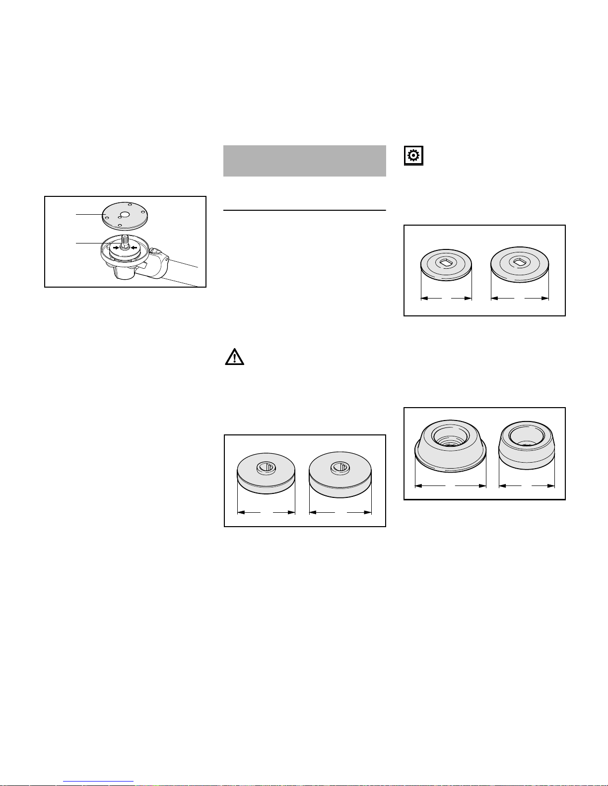
N Place the guard washer (6) on the
thrust washer – the whole collar
(arrows) on the shaft (1) must be
visible.
Mounting Hardware for Cutting
Attachment
The mounting hardware supplied
depends on the cutting attachment that
comes as original equipment with the
new machine.
The appropriate deflectors and
mounting hardware are available as
special accessories for subsequently
equipping the machine with different
cutting attachments – see chapter on
"Special Accessories".
Always use and assemble the cutting
attachment mounting hardware as
described in the chapter on "Mounting
the Cutting Attachment".
Thrust plate
– 60-mm diameter (A) version for
mowing heads ands grass cutting
blades.
– 65-mm diameter (A) version for
brush knives, shredder blades and
circular saw blades.
The thrust plate is necessary for
mounting all cutting attachments to the
gearbox.
Thrust washers
– 60-mm diameter (A) version for
grass cutting blades and circular
saw blades.
– 70-mm diameter (A) version for
brush knives and shredder blades.
Rider plates, guard ring and nut
– Approximately 80-mm diameter (A)
rider plate (1) for grass cutting
blades.
– Approximately 63-mm diameter (A)
rider plate (2) for circular saw
blades.
002BA506 KN
6
1
Mounting the Cutting
Attachment
681BA188 KN
A
A
681BA189 KN
A
A
681BA190 KN
A
A
Page 24
FS 510 C-M, FS 560 C-M
English
22
– Guard ring (3) for brush knives and
shredder blades.
Both these parts have the same
function:
– Nut (4) and thread on shaft are
protected against wear.
– Ground contact with metal cutting
attachment is minimized.
– Rider plate allows cutting
attachment to glide along close to
ground.
Always replace a worn rider plate and
guard ring in good time.
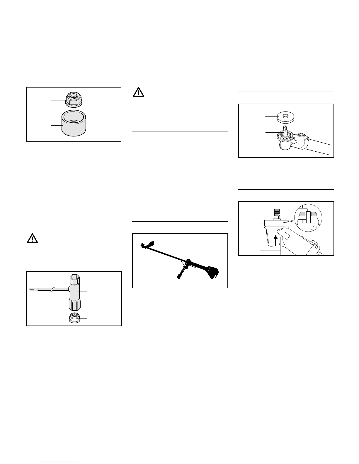
Nut and combination wrench
Metal cutting attachments are mounted
to the gearbox with the nut (4).
N Loosen and tighten the nut (4) with
the combination wrench (5).
If the mounting nut turns too freely, fit a
new one.
Cleaning the Gearbox and Cutting
Attachment Mounting Hardware
Clean the gearbox, the area surrounding
it, inside the grass shield and the cutting
attachment mounting hardware at
regular intervals. Also check for
contamination when changing the
cutting attachment and clean thoroughly
if necessary.
N Remove all cutting attachment
mounting hardware from the
gearbox for this purpose.
Preparations
N Lay your power tool on its back so
that the cutting attachment
mounting face is pointing up.
Fitting the Thrust Plate
N Slip the thrust plate (1) over the
shaft (2).
Block the drive shaft.
The shaft (2) must be blocked to install
and remove cutting attachments.
The shaft (2) can be blocked only if the
thrust plate (1) is properly fitted – the
stop pin (3) has to engage the thrust
plate.
N Insert the stop pin (3) in the bore in
the gearbox – apply slight pressure.
N Rotate shaft or cutting attachment
until the stop pin slips into position
and blocks the shaft.
The stop pin is held in position in the
gearbox by a rubber element.
681BA191 KN
4
3
4
681BA192 KN
5
002BA406 KN
002BA467 KN
1
2
002BA507 KN
1
2
3
Page 25
FS 510 C-M, FS 560 C-M
English
23
N Fit or remove the cutting attachment
– see chapter on "Mounting the
Cutting Attachment".
N Remove the stop pin.
Always remove the stop pin used to
block the shaft since the drive train will
otherwise be damaged when the engine
runs.
Mounting the Cutting Attachment
Use a deflector that matches the cutting
attachment – see "Mounting the
Deflector".
N Depending on the cutting
attachment you are using, refer to
the appropriate chapter below:
– Mounting Mowing Heads
– Mounting Grass Cutting Blades
– Mounting Brush Knives
– Mounting Shredder Blade
or
– Mounting Circular Saw Blades
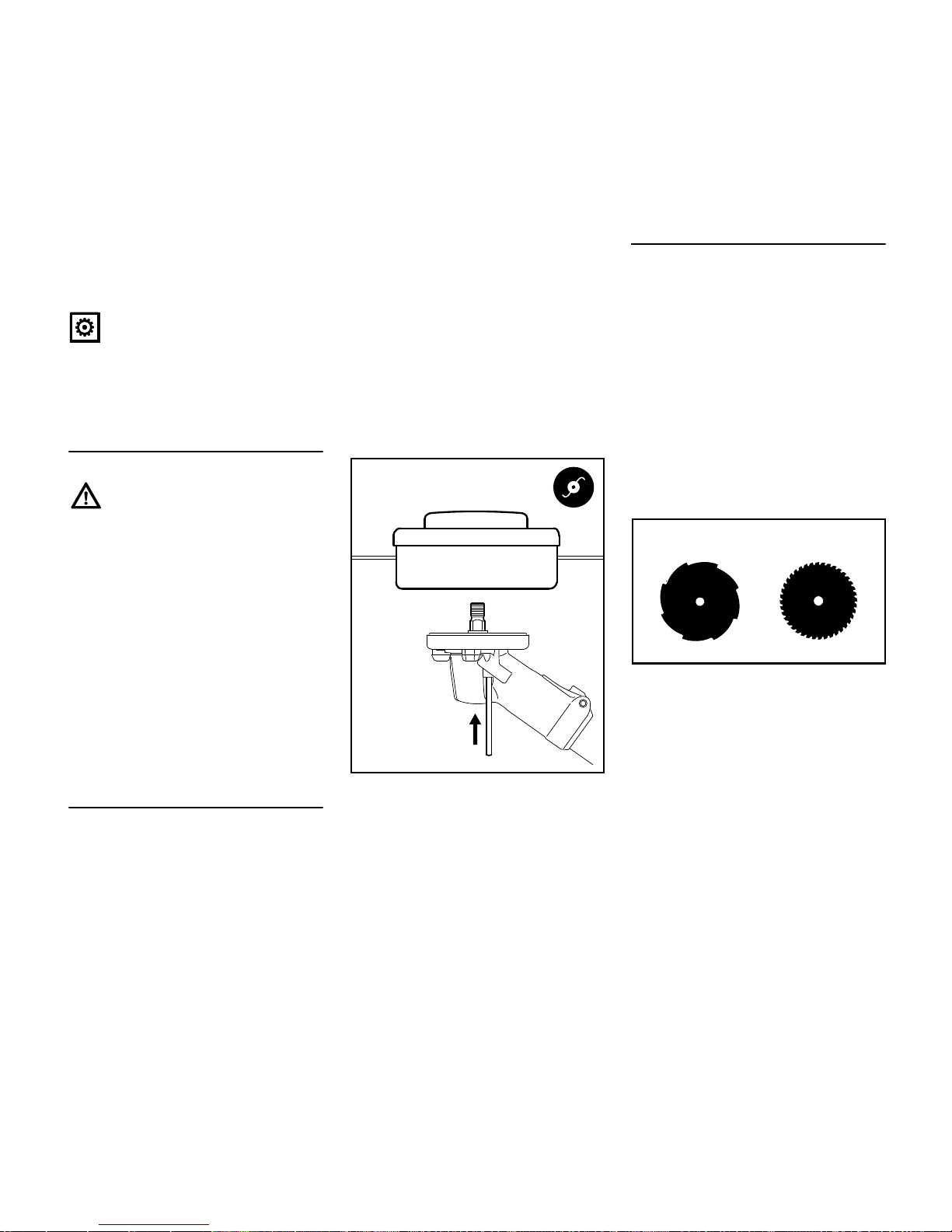
Mounting Mowing Heads
All approved mowing heads are
mounted to the gearbox in the same
way.
N Check that the deflector on the
machine is approved for mowing
heads – if not, perform the next two
steps.
N Remove grass shield with thrust
plate – if fitted.
N Remove the non-approved
deflector.
N Mount deflector for mowing heads.
N Fit grass shield together with 60-mm
diameter thrust plate.
N Block the drive shaft.
N Screw the mowing head
counterclockwise onto the shaft (1)
and tighten it down firmly.
Removing the mowing head
N Block the drive shaft.
N Unscrew the mowing head
clockwise.
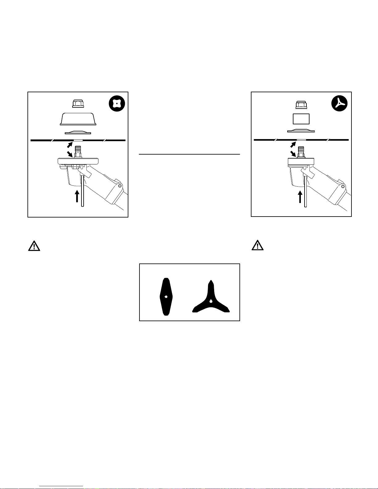
Mounting Grass Cutting Blades
N Check that the deflector on the
machine is approved for grass
cutting blades – if not, perform the
next two steps.
N Remove grass shield with thrust
plate – if fitted.
N Remove the non-approved
deflector.
N Mount deflector for grass cutting
blades and brush knives.
N Fit grass shield together with 60-mm
diameter thrust plate.
The cutting edges of the grass cutting
blades 255-8 (1) and 250-40 Spezial (2)
must point clockwise.
1
002BA468 KN
1
2
681BA186 KN
Page 26
FS 510 C-M, FS 560 C-M
English
24
N Place the cutting attachment (3) in
position.
Collar (a) must locate in the cutting
attachment's mounting hole (b).
N Fit the 60-mm diameter thrust
washer (4) – convex side must face
up.
N Fit the 80-mm diameter rider plate
(5).
N Block the drive shaft.
N Screw on the nut (6)
counterclockwise and tighten it
down firmly.
Removing the cutting attachment
N Block the drive shaft.
N Unscrew the mounting nut (6)
clockwise.
N Pull the cutting attachment with its
mounting hardware off the gearbox.
Mounting Brush Knives
N Check that the deflector on the
machine is approved for brush
knives – if not, perform the next two
steps.
N Remove grass shield with thrust
plate – if fitted.
N Remove the non-approved
deflector.
N Mount deflector for grass cutting
blades and brush knives.
N Use the 65-mm diameter thrust
plate.
Brush knives 305-2 (1) and 350-3(2)
may point in either direction – these
cutting attachments must be turned over
regularly to help avoid one-sided wear.
N Place the cutting attachment (3) in
position.
Collar (a) must locate in the cutting
attachment's mounting hole (b).
N Fit the 70-mm diameter thrust
washer (4) – convex side must face
up.
N Fit the guard ring (5) for brush
knives – opening must face up.
N Block the drive shaft.
N Screw on the nut (6)
counterclockwise and tighten it
down firmly.
a
002BA469 KN
b
4
5
3
6
1
2
681BA187 KN
3
002BA494 KN
3
6
4
b
a
5
Page 27
FS 510 C-M, FS 560 C-M
English
25
Removing the cutting attachment
N Block the drive shaft.
N Unscrew the mounting nut
clockwise.
N Pull the cutting attachment with its
mounting hardware off the gearbox.
Mounting shredder blade 320-2
N Check that the deflector on the
machine is approved for shredder
blades – if not, perform the next two
steps.
N Remove grass shield with thrust
plate – if fitted.
N Remove the non-approved
deflector.
N Mount deflector for shredder blade.
N Use the 65-mm diameter thrust
plate.
N Seal the unused tapped holes with
plugs.
N Place the shredder blade (1) in
position – cutting edges must point
clockwise and the vertical ends of
the blade must face up.
Collar (a) must locate in the cutting
attachment's mounting hole (b).
The cutting edges of the shredder blade
(1) must point upwards.
N Fit the 70-mm diameter thrust
washer (2) – convex side must face
up.
N Fit the shredder blade guard ring (3)
– opening must face up.
N Block the drive shaft.
N Screw on the nut (4)
counterclockwise and tighten it
down firmly.
Removing the cutting attachment
N Block the drive shaft.
N Unscrew the mounting nut
clockwise.
N Pull the cutting attachment with its
mounting hardware off the gearbox.
N If you intend to use a different
cutting attachment – remove the
shredder deflector.
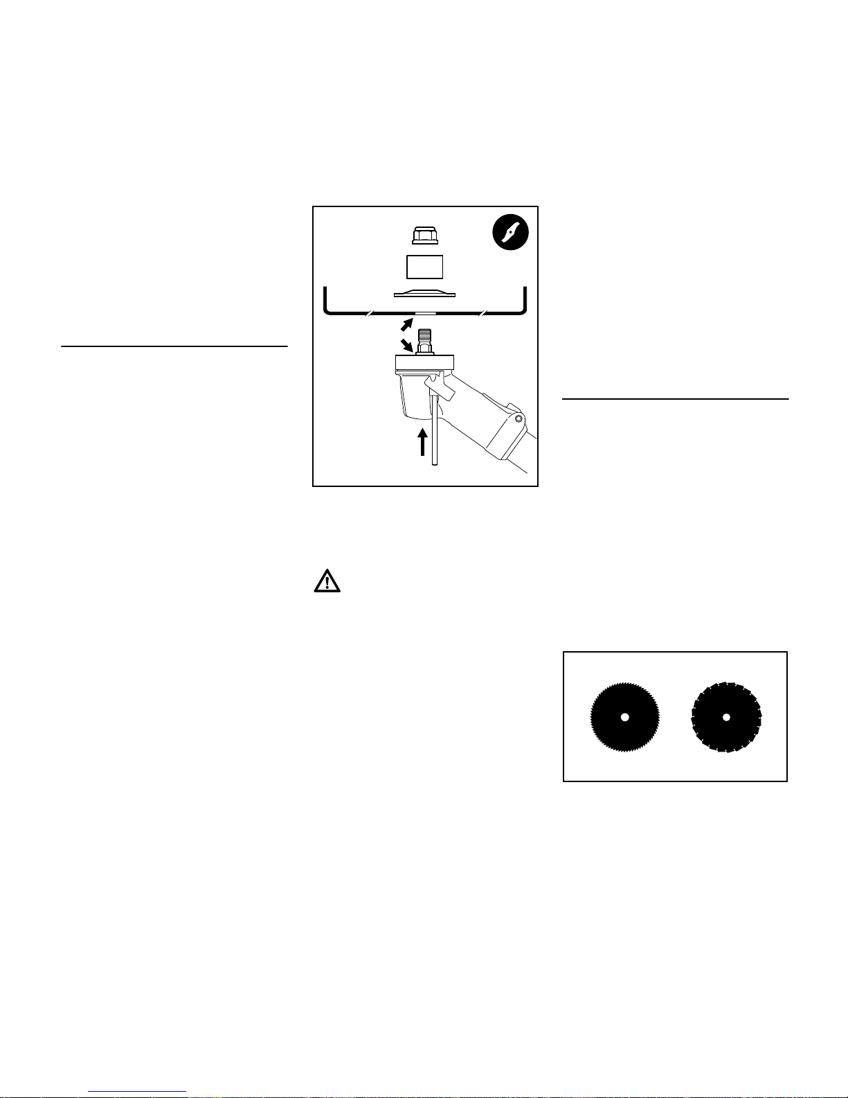
Mounting circular saw blades 225
N Check that the stop for circular saw
blades is already mounted to the
machine – if not, perform the next
two steps.
N Remove grass shield – if fitted.
N Remove deflector – if fitted.
N Mount limit stop for circular saw
blades.
N Use the 65-mm diameter thrust
plate.
N Seal the unused tapped holes with
plugs.
The cutting edges of circular saw blades
must point clockwise.
002BA470 KN
3
4
2
1
b
a
681BA165 KN
Page 28
FS 510 C-M, FS 560 C-M
English
26
N Place the cutting attachment (1) in
position.
Collar (a) must locate in the cutting
attachment's mounting hole (b).
N Fit the 60-mm diameter thrust
washer (2) – convex side must face
up.
N Fit the 63-mm diameter rider plate
(3).
N Block the drive shaft.
N Screw on the nut (4)
counterclockwise and tighten it
down firmly.
Removing the cutting attachment
N Block the drive shaft.
N Unscrew the mounting nut
clockwise.
N Pull the cutting attachment with its
mounting hardware off the gearbox.
This engine is certified to operate on
unleaded gasoline and with the mix ratio
50:1.
Your engine requires a mixture of highquality premium gasoline and highquality two-stroke air-cooled engine oil.
Use premium branded unleaded
gasoline with a minimum octane rating
of 89 (R+M)/2.
Note: Models equipped with a catalytic
converter require unleaded gasoline. A
few tankfuls of leaded gasoline can
reduce the efficiency of the catalytic
converter by more than 50%.
Fuel with a lower octane rating may
result in preignition (causing "pinging")
which is accompanied by an increase in
engine temperature. This, in turn,
increases the risk of the piston seizure
and damage to the engine.
The chemical composition of the fuel is
also important. Some fuel additives not
only detrimentally affect elastomers
(carburetor diaphragms, oil seals, fuel
lines etc.), but magnesium castings as
well. This could cause running problems
or even damage the engine. For this
reason it is essential that you use only
high-quality fuels!
Fuels with different percentages of
ethanol are being offered. Ethanol can
affect the running behaviour of the
engine and increase the risk of lean
seizure.
2
1
4
002BA471 KN
3
b
a
Fuel
Page 29
FS 510 C-M, FS 560 C-M
English
27
Gasoline with an ethanol content of
more than 10% can cause running
problems and major damage in engines
with a manually adjustable carburetor
and should not be used in such engines.
Engines equipped with M-Tronic can be
run on gasoline with an ethanol content
of up to 25% (E25).
Use only STIHL two-stroke engine oil or
equivalent high-quality two-stroke aircooled engine oils for mixing.
We recommend STIHL 50:1 two-stroke
engine oil since it is specially formulated
for use in STIHL engines.
Do not use BIA or TCW (two-stroke
water cooled) mix oils!
Use only STIHL 50:1 heavy-duty engine
oil or an equivalent quality two-stroke
engine oil for the fuel mix in models
equipped with a catalytic converter.
Take care when handling gasoline.
Avoid direct contact with the skin and
avoid inhaling fuel vapour.
The canister should be kept tightly
closed in order to avoid any moisture
getting into the mixture.
The fuel tank and the canister in which
fuel mix is stored should be cleaned
from time to time.
Fuel mix ratio
Only mix sufficient fuel for a few days
work, not to exceed 3 months of storage.
Store in approved safety fuel-canisters
only. When mixing, pour oil into the
canister first, and then add gasoline.
Dispose of empty mixing-oil canisters
only at authorized disposal locations.
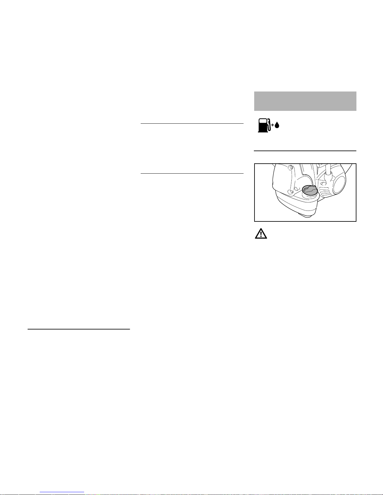
Preparations
When fueling on a slope, always position
the machine with the filler cap facing
uphill.
N On level ground, position the
machine so that the filler cap is
facing up.
N Before fueling, clean the filler cap
and the area around it to ensure that
no dirt falls into the tank.
Examples
Gasoline Oil (STIHL 50:1 or equiva-
lent high-quality oils)
liters liters (ml)
10.02(20)
5 0.10 (100)
10 0.20 (200)
15 0.30 (300)
20 0.40 (400)
25 0.50 (500)
Fueling
4900BA016 KN
Page 30
FS 510 C-M, FS 560 C-M
English
28
Opening screw-type tank cap
N Turn the cap counterclockwise until
it can be removed from the tank
opening.
N Remove the cap.
Filling up with fuel
Take care not to spill fuel while fueling
and do not overfill the tank.
STIHL recommends you use the STIHL
filler nozzle for fuel (special accessory).
N Filling up with fuel
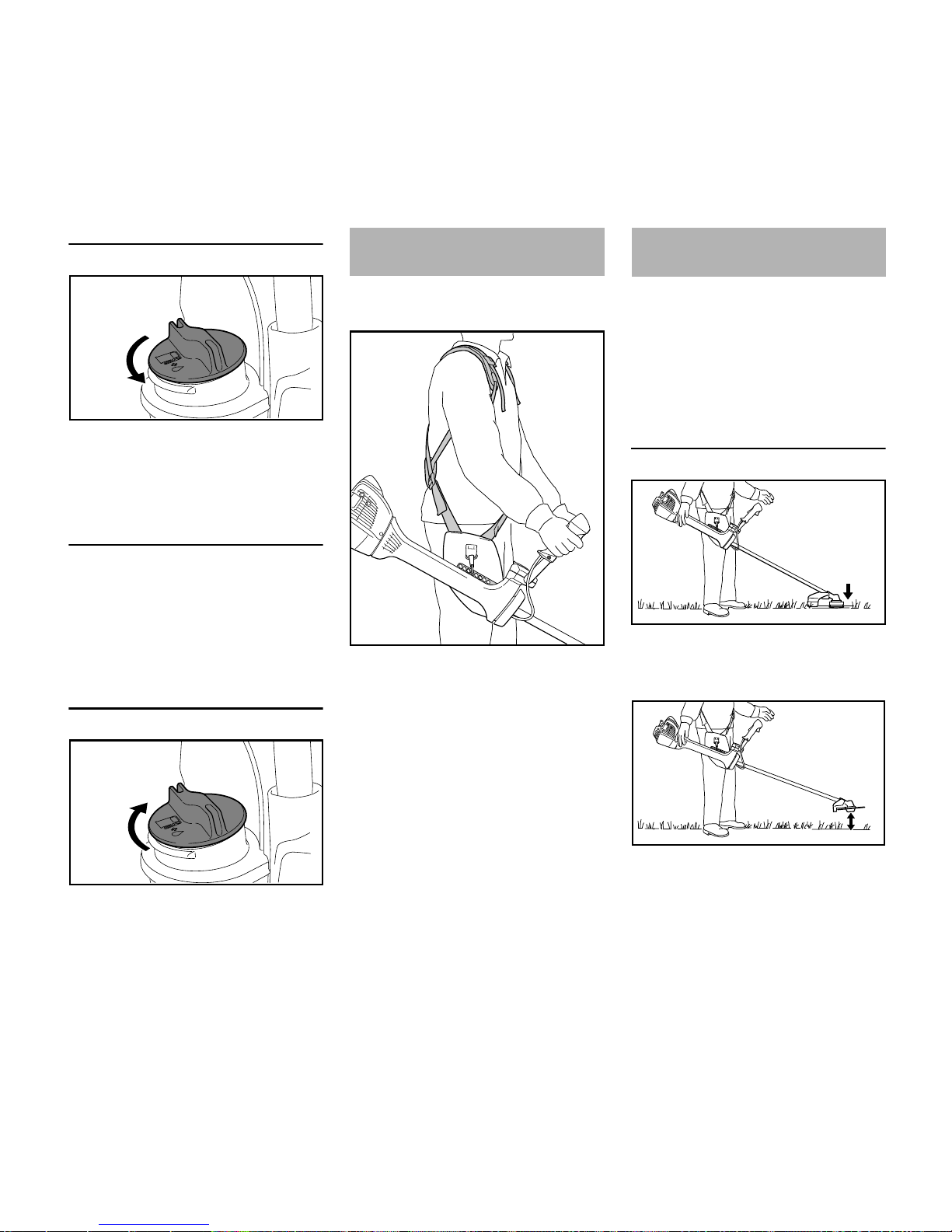
Closing screw-type tank cap
N Place the cap in the opening.
N Turn the cap clockwise as far as
stop and tighten it down as firmly as
possible by hand.
Fitting the full harness is described in
detail in the instruction sheet supplied.
N Put on the full harness (1).
N Adjust the length of the strap so that
the carabiner (2) is about a hand’s
width below your right hip.
N Attach the spring hook to the
machine's perforated strip (3).
Find the right attachment point for the
cutting attachment you are using – see
"Balancing the Brushcutter".
The machine will balance differently
depending on the cutting attachment
mounted.
N Let the machine swing on the
harness until it stops moving –
change the connection point if
necessary
Hanging positions
Mowing heads, grass cutting blades,
brush knives and shredder blades
should rest lightly on the ground.
Circular saw blades should "hover"
approx. 20 cm above the ground.
2709BA003 KN
2709BA004 KN
Fitting the Full Harness
3
002BA411 KN
1
2
Balancing the
Trimmer/Brushcutter
6BA009 KN
6BA010 KN
Page 31

FS 510 C-M, FS 560 C-M
English
29
Putting down the machine in an
emergency
As soon as it becomes apparent that a
dangerous situation is developing, the
machine must be put down quickly.
Practice setting down the machine
quickly. In order to avoid damage, when
practicing, do not throw the machine on
the ground.
Controls
1 Throttle trigger lockout
2 Throttle trigger
3 Stop switch with Run and Stop
positions. Press the momentary
contact stop switch to switch off the
ignition.
Function of stop switch and ignition
system
The stop switch is normally in the Run
position: Ignition is on in this position –
the engine is ready to start and may be
started. The ignition is switched off when
the stop switch is depressed. It is
automatically switched on again after
the engine comes to a standstill.
Symbols on choke knob
Start } – the engine is started in this
position.
Normal run position F – engine runs or
can fire.
Starting the Engine
N Press the fuel pump bulb (4) at least
five times – even if the bulb is filled
with fuel.
Starting / Stopping the
Engine
1
002BA474 KN
2
3
002BA481 KN
4
4900BA017 KN
Page 32

FS 510 C-M, FS 560 C-M
English
30
N Depress in the outer edge (arrows)
of the choke knob (5) and then turn
it to Start }.
Cranking
N Place the unit on the ground: It must
rest securely on the engine's guard
plate and the deflector. Check that
the cutting attachment is not
touching the ground of any other
obstacles.
N Make sure you have a firm footing –
either standing, stooping or
kneeling.
N Hold the unit firmly on the ground
with your left hand and press down
– do not touch the throttle trigger or
lockout lever.
Do not stand or kneel on the drive tube.
N Hold the starter grip with your right
hand.
Alternative method of starting:
With the machine suspended from the
harness and the engine at normal
operating temperature:
N Hold the machine firmly with your
right hand on the drive tube, handle
support or handlebar.
N With the machine behind you, press
it against the left side of your body.
N Hold the starter grip with your left
hand.
N Pull the starter grip steadily.
Do not pull out the starter rope all the
way – it might otherwise break.
N Do not let the starter grip snap back.
Guide it slowly back into the housing
so that the starter rope can rewind
properly.
N Continue cranking until the engine
runs.
As soon as the engine runs
N Make sure the engine runs
smoothly.
If the engine stalls:
N Continue cranking until the engine
runs.
As soon as the engine runs smoothly
N After a cold start, allow the engine to
warm up in the Start } position.
Machine is ready for use.
If you have started the machine for the
first time, refer to the notes on "Starting
for first time" in section "Other Hints on
Starting".
N Depress throttle trigger lockout and
pull the throttle trigger – the choke
knob moves to the Run F position.
The cutting attachment must not rotate
in the Run F position with the engine at
idling speed.
5
4900BA018 KN
6BA011 KN
6BA012 KN
6BA010 KN
6BA014 KN
Page 33

FS 510 C-M, FS 560 C-M
English
31
If the cutting attachment rotates when
the engine is idling, refer to notes in
chapter on "Adjusting the Thottle Cable"
or have the machine serviced by your
dealer. STIHL recommends a STIHL
servicing dealer.
N Attach the machine to the shoulder
strap.
N Machine is ready for use.
Stopping the Engine
N Depress the momentary contact
stop switch – the engine stops –
release the stop switch – it springs
back to the run position.
Other Hints on Starting
Starting for first time
N Depress the throttle trigger – do not
press down the throttle trigger
lockout.
If engine speed increases or the cutting
attachment rotates:
N Go to section "Stopping the
Engine".
N Go to "Adjusting the Throttle Cable".
If the engine speed does not increase,
your machine is ready for operation.
At very low outside temperatures
N Set the engine to winter operation if
necessary, see "Winter Operation".
N If the machine is very cold (frost on
machine), allow the engine to warm
up in the Start } position after
starting until normal operating
temperature is reached. Warning:
the cutting attachment rotates in this
position.
At very high outside temperatures
If the engine does not start after 10 pulls
in the Start } position:
N Start the engine in the Run F
position.
If the engine does not start
N Check that all settings are correct.
N Check that there is fuel in the tank
and refuel if necessary.
N Check that the spark plug boot is
properly connected.
N Repeat the starting procedure.
Fuel tank run until completely dry
N After refueling, press the fuel pump
bulb at least five times – even if the
bulb is filled with fuel.
N Start the engine.
002BA485 KN
6BA024 KN
Page 34

FS 510 C-M, FS 560 C-M
English
32
During break-in period
A factory-new machine should not be
run at high revs (full throttle off load) for
the first three tank fillings. This avoids
unnecessary high loads during the
break-in period. As all moving parts
have to bed in during the break-in
period, the frictional resistances in the
engine are greater during this period.
The engine develops its maximum
power after about 5 to 15 tank fillings.
During Operation
After a long period of full throttle
operation, allow the engine to run for a
short while at idle speed so that engine
heat can be dissipated by the flow of
cooling air. This protects enginemounted components (ignition,
carburetor) from thermal overload.
After Finishing Work
Storing for a short period: Wait for the
engine to cool down. Empty the fuel tank
and keep the machine in a dry place,
well away from sources of ignition, until
you need it again. For longer out-ofservice periods – see "Storing the
Machine".
General Information
The filter has a very long service life.
Do not remove the filter cover or replace
the air filter as long as there is no
noticeable loss of power.
Dirty air filters reduce engine power,
increase fuel consumption and make
starting more difficult.
Replacing the Air Filter
Only if there is a noticeable loss of
engine power
N Set the choke knob to }.
N Loosen the screws (1).
N Remove the filter cover (2).
N Clean away loose dirt from around
the filter (3) and inside the filter
cover.
The air filter (3) is a pleated paper filter
element.
N Remove and check the filter
element (3) – replace if paper or
frame is dirty or damaged.
N Unpack the new filter.
Do not bend or twist the filter before
installation as it might otherwise be
damaged – do not use damaged filters.
N Fit the filter in the filter housing.
N Fit the filter cover.
Use only high quality air filters to ensure
the engine is protected from abrasive
dust.
STIHL recommends you use only
original STIHL air filters. The high quality
standard of these parts guarantees
trouble-free operation, a long engine life
and very long filter service lives.
Operating Instructions Air filter
4900BA019 KN
1
4900BA020 KN
3
2
Page 35

FS 510 C-M, FS 560 C-M
English
33
Filter Element for Winter Operation
Maintenance and care of the special
filter element for winter operation are
described in the chapter on "Winter
Operation".
Exhaust emissions are controlled by the
design of the fundamental engine
parameters and components (e.g.
carburation, ignition, timing and valve or
port timing) without the addition of any
major hardware.
General Information
The M-Tronic controls fuel feed and
ignition timing electronically in all
operating conditions.
M-Tronic guarantees simple and fast
starts. The engine is started in the
Start } position irrespective of climatic
conditions or engine temperature. After
starting, the Start } position can be
maintained until the engine runs
smoothly.
M-Tronic ensures optimum engine
power at all times, very good
acceleration and automatic adjustment
to suit changing conditions.
For this reason there is no need to
change the carburetor setting – the
carburetor has no adjusting screws.
If the usual good running behavior and
engine power are not reached after an
extreme change in operating conditions,
contact your servicing dealer for
assistance.
STIHL recommends that you have
servicing and repair work carried out
exclusively by an authorized STIHL
servicing dealer.
Engine Management M-Tronic
Page 36

FS 510 C-M, FS 560 C-M
English
34
At temperatures below +10 °C
Preheating the carburetor
Repositioning a shutter allows heated air
to be drawn in from around the cylinder
and mixed with cold air – this helps
prevent carburetor icing.
An arrow (1) on the shroud indicates the
setting of the shutter (2) for summer or
winter operation. Meaning of symbols:
– "Sun" = summer operation
– "Snowflake" = winter operation
N Remove the screw (3) from the
shutter.
N Pull the shutter (2) out of the shroud.
N Rotate the shutter (2) from the
summer position to the winter
position and refit it.
N Secure the shutter in position with
the screw (3).
At temperatures between +10°C and
+20°C
The machine can normally be operated
in this temperature range with the
shutter (2) in the summer position.
Change the position of the shutter if
necessary.
At temperatures above +20°C
N Always return the shutter (2) to the
summer position.
Do not operate the machine in the winter
position at temperatures above +20°C
because there is otherwise a risk of
engine running problems and
overheating.
At temperatures below -10°C
In extreme wintry conditions
– Temperatures below -10°C
– Powder or drifting snow
it is advisable to use the optional "cover
plate kit".
Winter Operation
2
1
9926BA016 KN
2
9926BA017 KN
3
2
9926BA018 KN
Page 37

FS 510 C-M, FS 560 C-M
English
35
The cover plate kit contains the following
parts for converting the power tool:
4 Cover plate partially blanks off the
slots in the starter housing
5 Synthetic fabric filter element for the
air filter
– Instructions for converting the
machine
After installing the cover plate kit:
N Set the shutter (2) to the winter
position.
At temperatures above -10 °C
N Remove the parts of the cover plate
kit and refit the standard parts for
summer operation.
Depending on the ambient temperature:
N Set the shutter (2) to the summer or
winter position.
Cleaning the Air Filter
N Loosen filter cover mounting
screws.
N Remove the filter cover.
N Clean away loose dirt from around
the filter (5) and inside the filter
cover.
N Knock the filter (5) out on the palm
of your hand or blow it clear with
compressed air from the inside
outwards.
In case of stubborn dirt or sticky filter
fabric:
N Wash the filter in a clean, non-
flammable solution (e.g. warm
soapy water) and then dry.
Always replace a damaged filter.
N If the engine is down on power,
difficult to start or runs poorly at idle
speed, first check the spark plug.
N Fit a new spark plug after about 100
operating hours – or sooner if the
electrodes are badly eroded. Install
only suppressed spark plugs of the
type approved by STIHL – see
"Specifications".
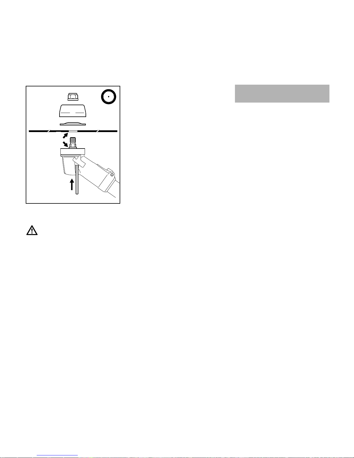
Removing the Spark Plug
N Rotate the screw (1) in the cap (2)
until the screw head projects from it.
N Lift the front of the cap (2) and push
it to the rear to disengage.
N Put the cap to one side.
N Remove the spark plug boot (3).
N Unscrew the spark plug.
4900BA021 KN
4
2
5
Spark Plug
4900BA022 KN
1
3
4900BA023 KN
Page 38

FS 510 C-M, FS 560 C-M
English
36
Checking the spark plug
N Clean dirty spark plug.
N Check electrode gap (A) and
readjust if necessary – see
"Specifications".
N Rectify the problems which have
caused fouling of the spark plug.
Possible causes are:
– Too much oil in fuel mix.
– Dirty air filter.
– Unfavorable running conditions.
If the spark plug comes with a
detachable adapter nut (1), screw the
adapter onto the thread and tighten it
down firmly to reduce the risk of arcing
and fire.
Installing the Spark Plug
N Screw the spark plug into the
cylinder.
N Press the spark plug boot firmly
onto the spark plug.
N Fit the cap (1) on the shroud from
the rear and push the lug (2) into the
opening (3) in the shroud at the
same time.
N Swing the cap forwards onto the
shroud, insert and tighten down the
screw (4) firmly.
If engine running behavior is still
unsatisfactory after servicing the air filter
and adjusting the throttle cable, the
cause may be the muffler.
Have the muffler checked by a servicing
dealer for contamination
(carbonization).
STIHL recommends that you have
servicing and repair work carried out
exclusively by an authorized STIHL
servicing dealer.
000BA039 KN
A
1
000BA045 KN
2
3
4900BA024 KN
Engine Running Behavior
Page 39

FS 510 C-M, FS 560 C-M
English
37
Removing the Rewind Starter
N Take out the screws (1).
N Lift away the rewind starter.
Replacing the Starter Rope and Rewind
Spring
N If either the starter rope or rewind
spring is broken, continue with
"Removing the Rope Rotor".
N If either the starter rope or rewind
spring are being replaced as a
precautionary measure, continue
with the following chapter.
Releasing Tension on Rewind Spring
N Use the tensioning wrench. It is
available as a special accessory.
N If necessary, swing the pawls (2)
inwards.
N Rotate the spring clip (3) out of the
recesses (4) in the carrier (5).
N Position the tensioning wrench in
the carrier so that the peg (6)
engages one of the recesses (4).
N Use starter grip to pull out the starter
rope as far as stop.
N Hold the tensioning wrench and the
starter mechanism steady so that
the rope does not rewind onto the
rope rotor.
N Grip the rope inside the housing,
pull it out to its full length and make
a loop.
N Allow tensioning wrench to rotate
slowly and thus release spring
tension – the rope winds itself
around the tensioning wrench in this
process until the spring is no longer
under tension.
N Remove the tensioning wrench from
the carrier.
Replacing the Starter Rope
and Rewind Spring
1 1
1 1
2709BA021 KN
9926BA036 KN
2
2
5
3
9926BA037 KN
6
4
9926BA038 KN
9926BA039 KN
9926BA040 KN
Page 40

FS 510 C-M, FS 560 C-M
English
38
Removing the Rope Rotor
N Use a screwdriver or suitable pliers
to remove the spring clip (3) from
the starter post.
N Carefully remove the E-clip (7).
N Carefully remove the carrier (5) with
pawls (2) and washer (8) and put
them to one side so that the pawls
and washer cannot fall out.
N Pull the rope rotor (9) off the starter
post.
The rewind spring may pop out and
uncoil during this operation – take care
to avoid the risk of injury.
N If the rewind spring needs to be
replaced, continue with "Replacing
the Rewind Spring".
N If the starter rope needs to be
replaced, continue with the
following chapter-
Replacing the Starter Rope
N Pry the cap out of the starter grip.
N Remove worn rope or remaining
rope from the rotor and starter grip.
N Thread the new rope through the
starter grip and tie a simple
overhand knot in its end as shown.
N Pull the knot back into the grip.
N Refit the cap in the grip.
N Thread the rope through the top of
the guide bushing (10) and rope
rotor (9).
N Tie a simple overhand knot in the
end of the rope.
N Pull the knot into the rope rotor – if
necessary, push the knot into the
rotor's recess.
N Go to "Installing the Rope Rotor".
7
3
9926BA041 KN
5
2
9926BA042 KN
9
8
3BA020 KN
3BA038 KN
10
9926BA043 KN
9
3BA022 KN
Page 41

FS 510 C-M, FS 560 C-M
English
39
Replacing the Rewind Spring
The bits of the spring may still be under
tension and could fly apart when you
remove the rope rotor and spring
housing. To reduce the risk of injury,
wear face protection and work gloves.
N Take out the screws (11).
N Remove the spring housing and
spring or bits of the spring.
N Lubricate the new, ready-to-fit
replacement spring in the new
spring housing with a few drops of
resin-free oil.
N Fit the replacement spring with
spring housing – the bottom plate
must face up.
If the spring pops out of the housing
during installation: Wear face protection
and work gloves and refit the spring in
the spring housing – clockwise – from
the outside inwards.
N Fit the screws.
Installing the Rope Rotor
N Coat the whole starter post
uniformly – including the grooves
(arrow) – with STIHL gear lubricant
(special accessory).
N Slip the rotor over the starter post –
turn it back and forth to engage the
anchor loop of the rewind spring.
N Slip the carrier with pawls and
washer over the starter post – turn it
back and forth to engage the anchor
loop of the rewind spring in the
carrier.
N Fit the E-clip (7) in the groove in the
starter post.
N Push the spring clip (3) into position
– it must point counterclockwise as
shown and engage the pawl's peg.
Tensioning the Rewind Spring
N Pull the starter rope out of the
housing as far as stop and make a
loop.
N Fit the tensioning wrench on the
carrier.
N Use the tensioning wrench to rotate
the rotor six full turns
counterclockwise – the rope winds
itself around the tensioning wrench
in this process.
N Hold the tensioning wrench steady
and unwind the rope.
11
9926BA044 KN
11
9926BA050 KN
7
3
9926BA045 KN
2
2
9926BA046 KN
9926BA047 KN
Page 42

FS 510 C-M, FS 560 C-M
English
40
N Pull out and straighten the twisted
rope at the starter grip.
N Hold the rope steady with the starter
grip.
N Release the tensioning wrench and
rope slowly so that it winds onto the
rotor.
N Remove the tensioning wrench.
The starter grip must locate firmly in the
guide bushing. If the grip droops to one
side: Add one more turn on the rope
rotor to increase spring tension.
When the starter rope is fully extended it
must still be possible to rotate the rotor
at least one more turn. If this is not the
case, the spring is overtensioned and
could break.
N Take one turn of the rope off the
rotor.
Installing the Rewind Starter
N Position and line up the rewind
starter on the engine.
N Insert the screws (1) and tighten
them down firmly.
For periods of 3 months or longer
N Drain and clean the fuel tank in a
well ventilated area.
N Dispose of fuel properly in
accordance with local
environmental requirements.
N Run the engine until the carburetor
is dry – this helps prevent the
carburetor diaphragms sticking
together.
N Remove, clean and inspect the
cutting attachment.
N Thoroughly clean the machine.
N Store the machine in a dry and
secure location – out of the reach of
children and other unauthorized
persons.
9926BA048 KN
9926BA049 KN
1 1
1 1
2709BA021 KN
Storing the Machine
Page 43

FS 510 C-M, FS 560 C-M
English
41
N Use a sharpening file (special
accessory) to sharpen dull cutting
attachments. In case of more
serious wear or nicks: Resharpen
with a grinder or have the work done
by a dealer – STIHL recommends a
STIHL servicing dealer.
N Resharpen frequently, take away as
little material as possible: two or
three strokes of the file are usually
enough.
N Resharpen the cutters (1) uniformly
– do not alter the contour or the
parent blade (2) in any way.
See cutting attachment packaging for
additional sharpening instructions.
Balancing
N After resharpening about 5 times,
check the cutting attachment for
out-of-balance on a STIHL balancer
(special accessory) or have it
checked by a dealer and rebalanced as necessary – STIHL
recommends a STIHL servicing
dealer.
Always check the mowing head for signs
of wear before replacing the nylon line.
If there are signs of serious wear,
replace the complete mowing head.
The nylon mowing line is referred to as
"nylon line" or "line" in the following.
The mowing head is supplied with
illustrated instructions for replacing the
nylon line. You should therefore keep
the instructions for the mowing head in a
safe place.
Adjustment of the nylon line is described
below.
Preparing the machine for replacing
nylon line
N Shut off the engine.
To reduce the risk of injury, always shut
off the engine before replacing nylon
line.
N Put the power tool on the ground
with the mowing head facing up.
N If necessary, remove the mowing
head.
Adjusting Nylon Line
AutoCut mowing head
N With the engine running, hold the
rotating mowing head above the
grass surface.
N Tap it on the ground once – fresh
line is advanced and the blade on
the deflector trims it to the right
length.
Fresh line is advanced every time the
mowing head is tapped on the ground.
For this reason observe the mowing
head's cutting performance during
operation. If the mowing head is tapped
on the ground too often, the line limiter
blade will unnecessarily cut off unused
lengths of nylon line.
Line feed operates only if both lines are
still at least 2.5 cm (1 in) long.
TrimCut mowing head
N Shut off the engine.
To reduce the risk of injury, always shut
off the engine before adjusting the nylon
line by hand.
N Pull the spool up – rotate it about 1/6
turn counterclockwise until it
engages – and allow it to spring
back.
N Pull ends of the lines outward.
Repeat the above procedure as
necessary until both lines are about 13
cm (5 in) long.
Rotating the spool from one stop to the
next advances about 4 cm (1 1/2 in) of
fresh line.
Sharpening Metal Cutting
Blades
681BA168 KN
2
2
1
2
1 1
Replacing Nylon Line
002BA508 KN
Page 44

FS 510 C-M, FS 560 C-M
English
42
Fitting Fresh Nylon Line
PolyCut mowing head
A length of nylon line can be fitted to the
PolyCut in place of the cutting blades.
N Shut off the engine.
To reduce the risk of injury, always shut
off the engine before refilling the mowing
head.
N Fit nylon line in mowing head as
described in the instructions
supplied.
PolyCut Mowing Head
Always check the mowing head for signs
of wear before installing new cutting
blades.
If there are signs of serious wear,
replace the complete mowing head.
The thermoplastic cutting blades are
referred to as "blades" in the following.
The mowing head is supplied with
illustrated instructions for replacing the
blades. You should therefore keep the
instructions for the mowing head in a
safe place.
Preparing the machine for installation of
new blades
N Shut off the engine.
To reduce the risk of injury, always shut
off the engine before installing new
blades.
N Put the power tool on the ground
with the mowing head facing up.
N Remove the mowing head.
Replacing the Cutting Blade
002BA406 KN
Page 45

FS 510 C-M, FS 560 C-M
English
43
Clamped Area of Handlebar
N Check the freedom of movement of
the handlebar (1) in the clamp
moldings (2) at regular intervals.
Handlebar is difficult to move
N Loosen the wing screw (3) just
enough for the handlebar to be
moved.
N Push the handlebar (1) sideways
out of the clamp.
N Soak a cloth in a clean, non-
flammable cleaning solution – do
not use cleaning agent containing
oil or grease.
N Thoroughly clean the clamp area of
the handlebar with the cloth and
cleaning solution.
N Line up the handlebar and secure it
in position with the wing screw.
Handlebar cannot be clamped firmly in
position
N Release handlebar in clamp as
described under "Handlebar is
difficult to move".
N Degrease clamp area on handlebar
and in clamp moldings.
N Line up the handlebar and secure it
in position with the wing screw.
Adjusting the Throttle Cable
The throttle cable can be adjusted only
when the machine is properly
assembled. The control handle must be
in the normal operating position.
If the following adjustments do not
produce the required result, have your
servicing dealer repair the machine.
STIHL recommends a STIHL servicing
dealer.
Check adjustment of throttle cable.
Error: Engine speed increases when
only the throttle trigger is depressed.
N Starting the Engine
N Depress the throttle trigger (2) – do
not press down the throttle trigger
lockout (1).
If the engine speed increases or if the
cutting attachment rotates, the throttle
cable has to be adjusted.
N Stopping the Engine
Adjusting the Throttle Cable
N Depress the throttle trigger lockout
(1) and the throttle trigger (2) as far
as stop and hold them in that
position.
Apply only sufficient pressure to hold the
levers against their stops.
N Rotate screw in throttle trigger 1/2
turn counterclockwise.
N Release the throttle trigger and
throttle trigger lockout.
Inspection and Maintenance
by User
2
1
4900BA025 KN
3
4900BA026 KN
1
1
6BA025 KN
2
002BA455 KN
Page 46

FS 510 C-M, FS 560 C-M
English
44
N Start the engine and check the
adjustment.
N Shut down the engine and repeat
adjustment if necessary.
Maintenance Work
STIHL recommends that you have
servicing and repair work carried out
exclusively by an authorized STIHL
servicing dealer.
Fuel Pickup Body in Tank
N Check the pickup body in the fuel
tank every year and have it replaced
if necessary.
The pickup body should be positioned in
the area of the tank shown in the
illustration.
Spark arrestor in muffler and spacer
N If the engine is down on power,
have the spark arrestor in the
muffler checked.
N Check spacer (2) for damage.
N Have damaged spacer (2) replaced
immediately.
Antivibration elements
Four antivibration elements (arrows) are
installed between the powerhead and
the drive tube. Have the system checked
if there is a noticeable increase in
vibrations.
Both vibration gaps (arrows) are preset
to the same width at the factory. If the
size of the two vibration gaps varies
greatly and/or one of them closes up,
have your servicing dealer repair the
antivibration system.
Inspections and Maintenance
by Dealer
2709BA022 KN
2709BA024 KN
2
4900BA028 KN
Page 47

FS 510 C-M, FS 560 C-M
English
45
Wear Guard on AV Housing
There is an easily replaced wear guard
on the side of the antivibration housing.
The guard may wear as a result of
rubbing against the side plate of the
harness durng operation and should be
replaced if necessary.
4900BA029 KN
Page 48

FS 510 C-M, FS 560 C-M
English
46
Maintenance and Care
The following intervals apply to normal operating conditions only. If your daily working time is longer or operating conditions are difficult (very dusty work area, etc.),
shorten the specified intervals accordingly.
before starting work
after finishing work or daily
after each refueling stop
weekly
monthly
every 12 months
if problem
if damaged
if required
Complete machine
Visual inspection (condition, leaks) XX
Clean X
Replace any damaged parts X
Control handle Check operation XX
Air filter, paper filter
Visual inspection XX
Replace
1)
X
Air filter, synthetic fabric filter
Visual inspection XX
Clean X
Replace XX
Fuel tank Clean X
Pickup body in fuel tank
Check
2)
X
Replace
2)
XXX
Engine idle speed
Check – the cutting attachment must not
turn
XX
If the cutting attachment turns when the
engine is idling, have machine repaired
by servicing dealer
2)
X
Spark plug
Readjust electrode gap X
Replace after every 100 operating hours
Cooling inlets
Visual inspection X
Clean X
Cylinder fins Clean
2)
X
Spark arrestor in muffler
Check
2)
X
Clean or replace
2)
X
Page 49

FS 510 C-M, FS 560 C-M
English
47
Spacer
Check X
Replace
2)
XX
Exhaust port
Decoke after first 139 hours of operation, then every 150 hours of operation
X
All accessible screws and nuts (not adjusting screws)
3)
Retighten X
Antivibration elements
Check
4)
XX
Replace
2)
X
Cutting attachment
Visual inspection XX
Replace X
Check tightness XX
Metal cutting attachment Sharpen XX
Safety labels Replace X
1)
Only if there is a noticeable loss of engine power
2)
STIHL recommends that this work be done by a STIHL servicing dealer
3)
Tighten down the muffler mounting screws firmly after first 10 to 20 hours of operation.
4)
see chapter "Inspection and Maintenance by Dealer", section "Antvibration elements"
The following intervals apply to normal operating conditions only. If your daily working time is longer or operating conditions are difficult (very dusty work area, etc.),
shorten the specified intervals accordingly.
before starting work
after finishing work or daily
after each refueling stop
weekly
monthly
every 12 months
if problem
if damaged
if required
Page 50

FS 510 C-M, FS 560 C-M
English
48
1 Fuel Filler Cap
2 Starter Grip
3 Shutter
4 Spark Plug Boot
5 Muffler with Spark Arresting Screen
6 Guard Plate
7 Throttle Trigger
8 Momentary Stop Switch
9 Throttle Trigger Lockout
10 Handlebar
11 Handle Support
12 Clamp Screw
13 Carrying Strip
14 Wear Guard
15 Choke Lever
16 Fuel Pump
17 Filter Cover
18 Fuel Tank
19 Spacer
# Serial Number
Main Parts
19
15
13
1
4
3
12
18
17
7
8
9
4900BA032 KN
#
16
2
6
5
14
10
11
Page 51

FS 510 C-M, FS 560 C-M
English
49
Definitions
1 Fuel Filler Cap
For closing the fuel tank.
2 Starter Grip
The grip of the pull starter, for
starting the engine.
3Shutter
With summer and winter positions.
Carburetor is heated in winter
position.
4 Spark Plug Boot
Connects the spark plug with the
ignition lead.
5 Muffler with Spark Arresting Screen
Muffler reduces exhaust noises and
diverts exhaust gases away from
operator.
Spark arresting screen is designed
to reduce the risk of fire.
6 Guard Plate
Protects the fuel tank.
7 Throttle Trigger
Controls the speed of the engine.
8 Momentary Stop Switch
Switches the engine's ignition off
and stops the engine.
9 Throttle Trigger Lockout
Must be depressed before the
throttle trigger can be activated.
10 Handlebar
For holding and controlling the unit
with the hand during operation.
11 Handle Support
Connects the shaft and bike handle.
12 Clamp Screw
Locks handlebar in selected
position.
13 Carrying Strip
The device to connect the clearing
saw to the harness.
14 Wear Guard
Protects the housing of the
antivibration-system from wear.
15 Choke Lever
Eases engine starting by enriching
mixture.
16 Fuel Pump
Provides additional fuel feed for a
cold start.
17 Filter Cover
Encloses and protects the air filter.
18 Fuel Tank
For fuel and oil mixture.
19 Spacer
Designed to reduce the risk of burns
and fire.
1 Mowing Head
2 Deflector for Mowing Heads
3 Line Limiting Blade
4 Metal Mowing Tool
5 Deflector for Metal Mowing Tools
Definitions
1 Mowing Head
The cutting attachment, i. e.
mowing head, for different
purposes.
2 Deflector for Mowing Heads
Designed to reduce the risk of injury
from foreign objects flung
backwards toward the operator by
the cutting attachment and from
contact with the cutting attachment.
3 Line Limiting blade
Metal blade at the deflector in order
to keep the line of the mowing head
at the proper length.
4 Metal Mowing Tool
The cutting attachment, i. e. blade,
made from metal for different
purposes.
5 Deflector for Metal Mowing Tools
Designed to reduce the risk of injury
from foreign objects flung
backwards toward the operator by
the cutting attachment and from
contact with the cutting attachment.
2
3
1
002BA475 KN
002BA476 KN
5
4
Page 52

FS 510 C-M, FS 560 C-M
English
50
6 Shredder Blade
7 Deflector for Shredder Blade
Definitions
6 Shredder Blade
Cutting attachment made of metal
for shredding, thinning and clearing
sturdy growth.
7 Deflector for Shredder Blade
Designed to reduce the risk of injury
from foreign objects flung
backwards toward the operator by
the cutting attachment and from
contact with the cutting attachment.
8 Circular Saw Blade
9 Limit Stop for Circular Saw Blade
Definitions
8 Circular Saw Blade
Cutting attachment made of metal
for cutting wood.
9 Limit Stop for Circular Saw Blade
Designed to position the brushcutter
steady against the wood in order to
reduce the risk of injury from loss of
control from reactive forces such as
thrust out.
EPA / CEPA
The Emission Compliance Period
referred to on the Emissions
Compliance Label indicates the number
of operating hours for which the engine
has been shown to meet Federal
emission requirements.
Category
Engine
Single cylinder two-stroke engine
FS 510 C
002BA477 KN
7
6
9
002BA478 KN
8
Specifications
A = 300 hours
B = 125 hours
C= 50hours
Displacement: 51.6 cm
3
Bore: 44.7 mm
Stroke: 32.9 mm
Engine power to ISO
8893:
2.4 kW (3.3 HP)
at 9,500 rpm
Idle speed: 2,500 rpm
Cut-off speed (rated): 12,300 rpm
Max. output shaft
speed (cutting
attachment): 9,210 rpm
Page 53

FS 510 C-M, FS 560 C-M
English
51
FS 560 C
Ignition System
Electronic magneto ignition
This spark ignition system meets all
requrements of the Canadian
Interference-Causing Equipment
Regulations ICES-002.
Fuel System
All position diaphragm carburetor with
integral fuel pump
Weight
Overall length
Features
Cutting Attachments
Mowing heads
1 STIHL AutoCut 40-4
2 STIHL TrimCut 51-2
3 STIHL PolyCut 41-3
Metal cutting attachments
4 Grass cutting blade 255-8
5 Grass cutting blade 250-40 Spezial
6 Brush knife 305-2 Spezial
7 Brush knife 350-3
8 Shredder blade 320-2
9 Scratcher tooth circular saw blade
225
10 Chisel tooth circular saw blade 225
11 Carbide tipped circular saw blade
225
Use cutting attachments only as
specified in the chapter on "Approved
Combinations of Cutting Attachment,
Deflector, Limit Stop and Harness".
Special accessories for cutting
attachments
– Nylon line for mowing heads, items
1 to 3
– Prewound spool with nylon line for
items 1 to 2
– Thermoplastic blades, pack of 12;
for item 3
– Transport guard for items 4 to 11
Displacement: 57.1 cm
3
Bore: 47.0 mm
Stroke: 32.9 mm
Engine power to ISO
8893:
2.8 kW (3.8 HP)
at 9,500 rpm
Idle speed: 2,500 rpm
Cut-off speed (rated): 12,300 rpm
Max. output shaft
speed (cutting
attachment): 9,210 rpm
FS 510 C
Spark plug (resistor
type): NGK BPMR7A
Electrode gap: 0.5 mm
FS 560 C
Spark plug (resistor
type):
NGK BPMR7A
Electrode gap: 0.5 mm
Fuel tank capacity:
FS 510 C: 0.99 l
FS 560 C: 0.99 l
dry, without cutting attachment and
deflector
FS 510 C-EM Z: 10.2 kg
FS 560 C-EM Z: 10.2 kg
without cutting attachment
FS 510 C-EM Z: 1760 mm
FS 560 C-EM Z: 1760 mm
C Convenience features
E ErgoStart
M M-Tronic
Z Fire-retardant equipment
Special Accessories
Page 54

FS 510 C-M, FS 560 C-M
English
52
Sharpening aids for metal cutting
attachments
– Flat sharpening files for items 4, 6 to
9
– File holder with round file, for item
10
– Saw set, for item 10
– STIHL balancer for items 4 to 11
– Sharpening templates (metal or
cardboard) for items 6 and 7
Mounting hardware for metal cutting
attachments
– 60 and 70 mm dia. thrust washers
– 60 and 65 mm dia. thrust plates
– Rider plate for mowing and sawing
applications
– Grass shield for mowing
attachments
– Guard ring for brush knives and
shredder blades (for use in place of
rider plate)
– Nut
Other Special Accessories
– Safety glasses
– Combination wrench
– Stop pin
– Full harness
– Shredder blade mounting kit
– Shredder blade retrofit kit
– Limit stop kit
– Cover plate kit for winter operation
– STIHL filler nozzle for fuels
– STIHL gear lubricant
Contact your STIHL dealer for more
information on these and other special
accessories.
Users of this machine may only carry out
the maintenance and service work
described in this user manual. All other
repairs must be carried out by a
servicing dealer.
STIHL recommends that you have
servicing and repair work carried out
exclusively by an authorized STIHL
servicing dealer. STIHL dealers are
regularly given the opportunity to attend
training courses and are supplied with
the necessary technical information.
When repairing the machine, only use
replacement parts which have been
approved by STIHL for this power tool or
are technically identical. Only use highquality replacement parts in order to
avoid the risk of accidents and damage
to the machine.
STIHL recommends the use of original
STIHL replacement parts.
Original STIHL parts can be identified by
the STIHL part number, the {
logo and the STIHL parts symbol K
(the symbol may appear alone on small
parts).
Maintenance and Repairs
Page 55

FS 510 C-M, FS 560 C-M
English
53
This statement is given voluntarily,
based on the MOU (Memorandum of
Understanding) as agreed in April 1999
between Environmental Canada and
STIHL Limited
Your Warranty Rights and Obligations
STIHL Limited is pleased to explain the
Emission Control System Warranty on
your equipment type engine. In Canada
new 1999 and later model year small offroad equipment engines must be
designed, built and equipped, at the time
of sale, to meet the U.S. EPA
regulations for small non road engines.
The equipment engine must be free from
defects in materials and workmanship
which cause it to fail to conform with
U.S. EPA standards for the first two
years of engine use from the date of sale
to the ultimate purchaser.
STIHL Limited must warrant the
emission control system on your small
off-road engine for the period of time
listed below provided there has been no
abuse, neglect or improper maintenance
of your small off-road equipment engine.
Your emission control system includes
parts such as the carburetor and the
ignition system. Also included may be
hoses, and connectors and other
emission-related assemblies.
Where a warrantable condition exists,
STIHL Limited will repair your small offroad equipment engine at no cost to you,
including diagnosis (if the diagnostic
work is performed at an authorized
dealer), parts, and labor.
Manufacturer's Warranty Coverage
In Canada 1999 and later model year
small off-road equipment engines are
warranted for two years. If any emissionrelated part on your engine is defective,
the part will be repaired or replaced by
STIHL Limited free of charge.
Owner's Warranty Responsibilities:
As the small off-road equipment engine
owner, you are responsible for the
performance of the required
maintenance listed in your instruction
manual. STIHL Limited recommends
that you retain all receipts covering
maintenance on your small off-road
equipment engine, but STIHL Limited
cannot deny warranty solely for the lack
of receipts or for your failure to ensure
the performance of all scheduled
maintenance.
Any replacement part or service that is
equivalent in performance and durability
may be used in non-warranty
maintenance or repairs, and shall not
reduce the warranty obligations of the
engine manufacturer.
As the small off-road equipment engine
owner, you should be aware, however,
that STIHL Limited may deny you
warranty coverage if your small off-road
equipment engine or a part has failed
due to abuse, neglect, improper
maintenance or unapproved
modifications.
You are responsible for presenting your
small off-road equipment engine to a
STIHL service center as soon as a
problem exists. The warranty repairs will
be completed in a reasonable amount of
time, not to exceed 30 days.
If you have any questions regarding your
warranty rights and responsibilities,
please contact a STIHL customer
service representative at www.stihl.ca
or you can write to:
STIHL Ltd.,
1515 Sise Road
Box 5666
CA-LONDON ONTARIO; N6A 4L6
Coverage by STIHL Limited
STIHL Limited warrants to the ultimate
purchaser and each subsequent
purchaser that your small off-road
equipment engine will be designed, built
and equipped, at the time of sale, to
meet all applicable regulations. STIHL
Limited also warrants to the initial
purchaser and each subsequent
purchaser that your engine is free from
defects in materials and workmanship
which cause the engine to fail to conform
with applicable regulations for a period
of two years.
Warranty Period
The warranty period will begin on the
date the utility equipment engine is
purchased by the initial purchaser and
you have signed and sent back the
warranty card to STIHL Ltd. If any
emission-related part on your engine is
defective, the part will be replaced by
STIHL Limited at no cost to the owner.
Any warranted part which is not
scheduled for replacement as required
maintenance, or which is scheduled only
for regular inspection to the effect of
"repair or replace as necessary" will be
warranted for the warranty period. Any
warranted part which is scheduled for
replacement as required maintenance
STIHL Limited Emission
Control Warranty Statement
Page 56

FS 510 C-M, FS 560 C-M
English
54
will be warranted for the period of time
up to the first scheduled replacement
point for that part.
Diagnosis
You, as the owner, shall not be charged
for diagnostic labor which leads to the
determination that a warranted part is
defective. However, if you claim
warranty for a component and the
machine is tested as non-defective,
STIHL Limited will charge you for the
cost of the emission test. Mechanical
diagnostic work will be performed at an
authorized STIHL servicing dealer.
Emission test may be performed either
at
STIHL Incorporated,
536 Viking Drive, P.O. Box 2015,
Virginia Beach, VA 23452
or at any independent test laboratory.
Warranty Work
STIHL Limited shall remedy warranty
defects at any authorized STIHL
servicing dealer or warranty station. Any
such work shall be free of charge to the
owner if it is determined that a warranted
part is defective. Any manufacturerapproved or equivalent replacement
part may be used for any warranty
maintenance or repairs on emissionrelated parts and must be provided
without charge to the owner. STIHL
Limited is liable for damages to other
engine components caused by the
failure of a warranted part still under
warranty.
The following list specifically defines the
emission-related warranted parts:
– Air Filter
– Carburetor
– Fuel Pump
– Choke (Cold Start Enrichment
System)
– Control Linkages
– Intake Manifold
– Magneto or Electronic Ignition
System (Ignition Module)
– Spark Plug
– Catalytic Converter (if applicable)
– Fuel Tank
– Fuel Cap
– Fuel Line
– Fuel Line Fittings
– Clamps
– Fasteners
Where to make a Claim for Warranty
Service
Bring the product to any authorized
STIHL servicing dealer and present the
signed warranty card.
Maintenance Requirements
The maintenance instructions in this
manual are based on the application of
the recommended 2-stroke fuel-oil
mixture (see also instruction "Fuel").
Deviations from this recommendation
regarding quality and mixing ratio of fuel
and oil may require shorter maintenance
intervals.
Limitations
This Emission Control Systems
Warranty shall not cover any of the
following:
1. repair or replacement required
because of misuse, neglect or lack
of required maintenance
2. repairs improperly performed or
replacements not conforming to
STIHL Limited specifications that
adversely affect performance
and/or durability, and alterations or
modifications not recommended or
approved in writing by STIHL
Limited
3. replacement of parts and other
services and adjustments
necessary for required maintenance
at and after the first scheduled
replacement point
Page 57

Notice d'emploi d'origineImprimé sur papier blanchi sans chlore
L'encre d'imprimerie contient des huiles végétales, le papier
est recyclable.
© ANDREAS STIHL AG & Co. KG, 2012
0458-772-8221-A. VA0.A12.
0000005287_001_F
FS 510 C-M, FS 560 C-M
français
55
{
La présente Notice d'emploi est protégée par des droits d'auteur. Tous droits réservés, en particulier tout droit de copie, de traduction et de traitement avec des systèmes électroniques quelconques.
Table des matières
Chère cliente, cher client,
nous vous félicitons d'avoir choisi un
produit de qualité de la société STIHL.
Ce produit a été fabriqué avec les
procédés les plus modernes et les
méthodes de surveillance de qualité les
plus évoluées. Nous mettons tout en
œuvre pour que ce dispositif vous
assure les meilleurs services, de telle
sorte que vous puissiez en être
parfaitement satisfait.
Pour toute demande de renseignements
complémentaires, veuillez vous
adresser à votre revendeur ou
directement à l'importateur de votre
pays.
Hans Peter Stihl
Indications concernant la présente
Notice d'emploi 56
Prescriptions de sécurité et
techniques de travail 56
Combinaisons autorisées d'outil de
coupe, de capot protecteur, de
butée et de harnais 68
Montage du guidon 69
Réglage du câble de commande
des gaz 73
Montage des dispositifs de sécurité 73
Montage de l'outil de coupe 77
Carburant 83
Ravitaillement en carburant 84
Utilisation du harnais double 85
Équilibrage du dispositif 85
Mise en route / arrêt du moteur 86
Instructions de service 89
Filtre à air 90
Gestion moteur 91
M-Tronic 91
Utilisation en hiver 91
Bougie 93
Fonctionnement du moteur 94
Remplacement du câble de
lancement / du ressort de rappel 95
Rangement du dispositif 99
Affûtage des outils de coupe
métalliques 99
Remplacement du fil de coupe 100
Remplacement du couteau 101
Contrôle et maintenance par
l'utilisateur 102
Contrôle et maintenance par le
revendeur spécialisé 103
Instructions pour la maintenance et
l'entretien 105
Principales pièces 107
Caractéristiques techniques 109
Accessoires optionnels 110
Instructions pour les réparations 111
Garantie de la Société STIHL
Limited relative au système
antipollution 112
Page 58

FS 510 C-M, FS 560 C-M
français
56
Pictogrammes
Les pictogrammes appliqués sur la
machine sont expliqués dans la
présente Notice d'emploi.
Suivant la machine et son équipement
spécifique, les pictogrammes suivants
peuvent y être appliqués.
Repérage des différents types de textes
Avertissement contre un risque
d'accident et de blessure ainsi que de
graves dégâts matériels.
Avertissement contre un risque de
détérioration de la machine ou de
certains composants.
Développement technique
La philosophie de STIHL consiste à
poursuivre le développement continu de
toutes ses machines et de tous ses
dispositifs ; c'est pourquoi nous devons
nous réserver tout droit de modification
de nos produits, en ce qui concerne la
forme, la technique et les équipements.
On ne pourra donc en aucun cas se
prévaloir des indications et illustrations
de la présente Notice d'emploi à l'appui
de revendications quelconques.
Respecter les prescriptions de sécurité
nationales spécifiques publiées par ex.
par les caisses professionnelles
d'assurances mutuelles, caisses de
sécurité sociale, services pour la
protection du travail et autres
organismes compétents.
Une personne qui travaille pour la
première fois avec cette machine doit
demander au vendeur ou à une autre
personne compétente de lui montrer
comment l'utiliser en toute sécurité – ou
participer à un stage de formation.
Indications concernant la
présente Notice d'emploi
Réservoir à carburant ;
mélange d'essence et
d'huile moteur
Actionner la soupape de
décompression
Pompe d'amorçage
manuelle
Actionner la pompe
d'amorçage manuelle
Tube de graisse
Canalisation de l'air
aspiré : utilisation en été
Canalisation de l'air
aspiré : utilisation en
hiver
Chauffage de poignées
Prescriptions de sécurité et
techniques de travail
En travaillant avec cette
machine, il faut respecter
des prescriptions de
sécurité particulières,
parce que l'outil de coupe
tourne à très haute
vitesse.
Avant la première mise
en service, lire attentivement et intégralement la
présente Notice d'emploi.
La conserver
précieusement pour pouvoir la relire lors d'une
utilisation ultérieure. Un
utilisateur qui ne respecte
pas les instructions de la
Notice d'emploi risque
d'occasionner un accident grave, voire même
mortel.
Page 59

FS 510 C-M, FS 560 C-M
français
57
Les jeunes encore mineurs ne sont pas
autorisés à travailler avec cette machine
– une seule exception est permise pour
des apprentis de plus de 16 ans
travaillant sous surveillance.
Veiller à ce que des spectateurs
éventuels, en particulier des enfants, ou
des animaux restent à une distance
suffisante.
Lorsque la machine n'est pas utilisée, la
ranger en veillant à ce qu'elle ne
présente aucun danger pour d'autres
personnes. Conserver la machine à un
endroit adéquat, de telle sorte qu'elle ne
puisse pas être utilisée sans
autorisation.
L'utilisateur est responsable des
blessures qui pourraient être infligées à
d'autres personnes, de même que des
dégâts matériels causés.
Ne confier la machine qu'à des
personnes familiarisées avec ce modèle
et sa manipulation – toujours y joindre la
Notice d'emploi.
L'utilisation de dispositifs à moteur
bruyants peut être soumise à des
prescriptions nationales ou locales
précisant les créneaux horaires à
respecter.
L'utilisateur de la machine doit être
reposé, en bonne santé et en bonne
condition physique.
Une personne à laquelle il est interdit
d'effectuer des travaux fatigants – pour
des questions de santé – devrait
consulter son médecin et lui demander
si elle peut travailler avec un dispositif à
moteur.
Uniquement pour les personnes qui
portent un stimulateur cardiaque : le
système d'allumage de cette machine
engendre un champ électromagnétique
de très faible intensité. Une influence sur
certains types de stimulateurs
cardiaques ne peut pas être totalement
exclue. Afin d'écarter tout risque pour la
santé, STIHL recommande aux
personnes portant un stimulateur
cardiaque de consulter leur médecin
traitant et le fabricant du stimulateur
cardiaque.
Il est interdit de travailler avec la
machine après avoir consommé de
l'alcool ou de la drogue ou bien après
avoir pris des médicaments qui risquent
de limiter la capacité de réaction.
Utiliser la machine – suivant les outils de
coupe assignés – exclusivement pour
faucher de l'herbe ou pour couper des
plantes sauvages, des buissons, des
broussailles, des arbustes etc.
Il est interdit d'utiliser cette machine
pour d'autres travaux – risque
d'accident !
Monter exclusivement des outils de
coupe ou accessoires autorisés par
STIHL pour cette machine, ou des
pièces similaires du point de vue
technique. Pour toute question à ce
sujet, s'adresser à un revendeur
spécialisé. Utiliser exclusivement des
outils ou accessoires de haute qualité.
Sinon, des accidents pourraient survenir
ou la machine risquerait d'être
endommagée.
STIHL recommande d'utiliser des outils
et accessoires d'origine STIHL. Leurs
caractéristiques sont optimisées tout
spécialement pour ce produit, et pour
satisfaire aux exigences de l'utilisateur.
N'apporter aucune modification à cette
machine – cela risquerait d'en
compromettre la sécurité. STIHL décline
toute responsabilité pour des blessures
ou des dégâts matériels occasionnés en
cas d'utilisation d'équipements
rapportés non autorisés.
Pour le nettoyage de cette machine, ne
pas utiliser un nettoyeur haute pression.
Le puissant jet d'eau risquerait
d'endommager certaines pièces de la
machine.
Le capot protecteur de la machine ne
peut pas protéger l'utilisateur contre
tous les objets (pierres, morceaux de
verre ou de fil de fer etc.) projetés par
l'outil de coupe. Ces objets peuvent
ricocher et toucher l'utilisateur.
Vêtements et équipement
Porter des vêtements et équipements de
protection réglementaires.
Ne pas porter des vêtements qui
risqueraient de se prendre dans le bois,
les broussailles ou les pièces en
mouvement de la machine. Ne porter ni
écharpe ou cravate, ni bijoux. Les
personnes aux cheveux longs doivent
les nouer et les assurer (foulard,
casquette, casque etc.).
Les vêtements doivent
être fonctionnels et
garantir une liberté de
mouvement totale. Porter des vêtements bien
ajustés – une combinaison, mais pas une blouse
de travail.
Page 60

FS 510 C-M, FS 560 C-M
français
58
Seulement pour le travail avec des têtes
faucheuses, il est permis de porter des
chaussures robustes avec semelle
crantée antidérapante.
Une visière n'offre pas une protection
oculaire suffisante.
Porter un dispositif antibruit
« individuel » – par ex. des capsules
protège-oreilles.
STIHL propose une gamme complète
d'équipements pour la protection
individuelle.
Transport de la machine
Toujours arrêter le moteur.
Porter la machine en la laissant
suspendue au harnais ou en la tenant
par le tube, de telle sorte qu'elle soit bien
équilibrée. Pour éviter le risque de
blessure en cas de contact avec l'outil
de coupe métallique – monter le
protecteur de transport sur l'outil de
coupe.
Pour le transport dans un véhicule :
assurer la machine de telle sorte qu'elle
ne risque pas de se renverser, d'être
endommagée ou de perdre du
carburant.
Ravitaillement
Arrêter le moteur avant de refaire le
plein.
Ne pas refaire le plein tant que le moteur
est très chaud – du carburant peut
déborder – risque d'incendie !
Ouvrir prudemment le bouchon du
réservoir à carburant, afin que la
surpression interne s'échappe
lentement et que du carburant ne soit
pas éjecté.
Faire le plein exclusivement à un endroit
bien aéré. Si l'on a renversé du
carburant, essuyer immédiatement la
machine. Ne pas se renverser du
carburant sur les vêtements – le cas
échéant, se changer immédiatement.
Cela réduit le risque de desserrage du
bouchon du réservoir sous l'effet des
vibrations du moteur, et de fuite de
carburant.
S'assurer que la machine ne présente
pas de fuite – si l'on constate une fuite
de carburant, ne pas mettre le moteur en
marche – danger de mort par suite de
brûlures !
Porter des chaussures de
sécurité avec semelle
antidérapante et coquille
d'acier.
Pour les travaux de
dépressage, la coupe de
broussailles assez
hautes et chaque fois
qu'un risque de chute
d'objets se présente, porter un casque. Porter une
visière pour la protection
du visage et, en plus,
porter impérativement
des lunettes de protection – risque de blessure
par des objets soulevés
ou projetés.
Porter des gants
robustes.
Ne pas toucher aux
pièces très chaudes de la
machine ou au réducteur
– risque de brûlure !
002BA479 KN
L'essence est un carburant extrêmement
inflammable – rester à
une distance suffisante
de toute flamme ou
source d'inflammation –
ne pas renverser du carburant – ne pas fumer.
Après le ravitaillement,
visser le bouchon du
réservoir le plus fermement possible.
Page 61

FS 510 C-M, FS 560 C-M
français
59
Avant la mise en route
S'assurer que la machine se trouve en
parfait état pour un fonctionnement en
toute sécurité – conformément aux
indications des chapitres
correspondants de la Notice d'emploi :
– utiliser exclusivement la
combinaison autorisée d'outil de
coupe, de capot protecteur, de
poignée et de harnais ; toutes les
pièces doivent être montées
impeccablement ;
– le bouton d'arrêt doit pouvoir être
enfoncé facilement ;
– le levier de starter, le blocage de
gâchette d'accélérateur et la
gâchette d'accélérateur doivent
fonctionner facilement – la gâchette
d'accélérateur doit revenir
automatiquement en position de
ralenti, sous l'effet de son ressort.
En partant de la position } du
levier de starter, ce levier doit
revenir dans la position de marche
normale F, sous l'effet de son
ressort, lorsqu'on enfonce en même
temps le blocage de gâchette
d'accélérateur et la gâchette
d'accélérateur ;
– contrôler le serrage du contact de
câble d'allumage sur la bougie – un
contact desserré peut provoquer un
jaillissement d'étincelles risquant
d'enflammer le mélange carburé qui
aurait pu s'échapper – risque
d'incendie !
– outil de coupe ou outil à rapporter :
monté correctement, bien serré et
dans un état impeccable ;
– contrôler si les dispositifs de
protection (par ex. le capot
protecteur de l'outil de coupe, le bol
glisseur) ne sont pas endommagés
ou usés. Remplacer les pièces
endommagées. Il est interdit
d'utiliser la machine avec un capot
protecteur endommagé ou un bol
glisseur usé (lorsque l'inscription et
les flèches ne sont plus
reconnaissables) ;
– n'apporter aucune modification aux
dispositifs de commande et de
sécurité ;
– les poignées doivent être propres et
sèches, sans huile ni autres
salissures – un point très important
pour que l'on puisse manier la
machine en toute sécurité.
– ajuster le harnais et la poignée (les
poignées) suivant la taille de
l'utilisateur. À ce sujet, respecter les
indications des chapitres
« Utilisation du harnais » et
« Équilibrage du dispositif ».
Il est interdit d'utiliser la machine si elle
ne se trouve pas en parfait état de
fonctionnement – risque d'accident !
Pour parer à toute éventualité, à
l'utilisation d'un harnais : s'entraîner
pour savoir se dégager rapidement de la
machine. Lors de cet exercice, ne pas
jeter la machine sur le sol, pour ne pas
risquer de l'endommager.
Mise en route du moteur
Aller au moins à 3 mètres du lieu où l'on
a fait le plein – et ne pas lancer le moteur
dans un local fermé.
Pour lancer le moteur, il faut
impérativement se tenir bien d'aplomb,
sur une aire stable et plane – l'outil de
coupe ne doit entrer en contact ni avec
le sol, ni avec un objet quelconque, car il
peut déjà être entraîné au démarrage du
moteur.
La machine doit être maniée par une
seule personne – ne pas tolérer la
présence d'autres personnes dans un
rayon de 15 m – pas même à la mise en
route du moteur – risque de blessure par
des objets projetés !
Écarter toute matière aisément
inflammable (par ex. copeaux,
morceaux d'écorce, herbe sèche,
carburant) du flux des gaz
d'échappement et du silencieux très
chauds – risque d'incendie !
Prise en mains et utilisation
Toujours tenir fermement la machine à
deux mains, par les poignées.
Éviter tout contact avec
l'outil de coupe – risque
de blessure !
Ne pas lancer le moteur
en tenant la machine « à
bout de bras » – pour la
mise en route du moteur,
procéder comme décrit
dans la Notice d'emploi.
Lorsqu'on relâche la
gâchette d'accélérateur,
l'outil de coupe tourne
encore pendant quelques
instants – par inertie !
Page 62

FS 510 C-M, FS 560 C-M
français
60
Toujours se tenir dans une position
stable et sûre.
Tenir la poignée de commande de la
main droite et l'autre poignée du guidon
de la main gauche.
Au cours du travail
Toujours se tenir dans une position
stable et sûre.
En cas d'urgence ou de danger
imminent, enfoncer le bouton d'arrêt
pour arrêter le moteur.
À part l'utilisateur, personne ne doit se
trouver dans un rayon de 15 m de la
machine en marche – risque de blessure
par des objets projetés ! Respecter
également cette distance par ex. par
rapport à des véhicules garés, vitres etc.
– pour éviter de causer des dégâts
matériels !
Veiller à ce que le ralenti soit
correctement réglé – de telle sorte
qu'après le relâchement de la gâchette
d'accélérateur l'outil de coupe ne soit
plus entraîné et s'arrête. Si l'outil de
coupe tourne au ralenti, malgré un
réglage correct, faire réparer la machine
par le revendeur spécialisé. STIHL
recommande de s'adresser au
revendeur spécialisé STIHL.
Faire particulièrement attention sur un
sol glissant – mouillé, couvert de neige
ou de verglas – de même qu'en
travaillant à flanc de coteau ou sur un sol
inégal etc. – risque de dérapage !
Faire attention aux obstacles : souches
d'arbres, racines – pour ne pas risquer
de trébucher !
Travailler seulement depuis le sol, ne
jamais monter sur un échafaudage
instable – jamais sur une échelle ou une
nacelle élévatrice.
En travaillant avec des protège-oreilles,
il faut faire tout particulièrement
attention – parce que des bruits
signalant un danger (cris, signaux
sonores etc.) sont moins bien
perceptibles.
Faire des pauses à temps pour ne pas
risquer d'atteindre un état de fatigue ou
d'épuisement qui pourrait entraîner un
accident !
Travailler calmement, de manière bien
réfléchie – seulement dans de bonnes
conditions de visibilité et d'éclairage.
Prendre les précautions utiles pour
exclure le risque de blesser d'autres
personnes.
En travaillant dans des fossés, des
dépressions de terrain ou des espaces
restreints, toujours prendre soin
d'assurer une ventilation suffisante –
danger de mort par intoxication !
En cas de nausée, de maux de tête, de
troubles de la vue (par ex.
rétrécissement du champ de vision) ou
de l'ouïe, de vertige ou de manque de
concentration croissant, arrêter
immédiatement le travail – ces
symptômes peuvent, entre autres, être
causés par une trop forte concentration
de gaz d'échappement dans l'air
ambiant – risque d'accident !
Éviter les émissions de bruits et de gaz
d'échappement inutiles. Ne pas laisser
le moteur en marche lorsque la machine
n'est pas utilisée – accélérer seulement
pour travailler.
Ne pas fumer en travaillant ou à
proximité de la machine – risque
d'incendie ! Des vapeurs d'essence
inflammables peuvent s'échapper du
système d'alimentation en carburant.
002BA480 KN
15m (50ft)
Dès que le moteur est en
marche, il dégage des
gaz d'échappement
toxiques. Ces gaz peuvent être inodores et
invisibles, et renfermer
des hydrocarbures
imbrûlés et du benzène.
Ne jamais travailler avec
la machine dans des
locaux fermés ou mal
aérés – pas non plus si le
moteur est équipé d'un
catalyseur.
Page 63

FS 510 C-M, FS 560 C-M
français
61
Les poussières, les vapeurs et les
fumées dégagées au cours du travail
peuvent nuire à la santé. En cas de fort
dégagement de poussière ou de fumée,
porter un masque respiratoire.
Si la machine a été soumise à des
sollicitations sortant du cadre de
l'utilisation normale (par ex. si elle a été
soumise à des efforts violents, en cas de
choc ou de chute), avant de la remettre
en marche, il faut impérativement
s'assurer qu'elle se trouve en parfait état
de fonctionnement – voir également
« Avant la mise en route du moteur ».
Contrôler tout particulièrement
l'étanchéité du système de carburant et
la fiabilité des dispositifs de sécurité. Il
ne faut en aucun cas continuer d'utiliser
la machine si la sécurité de son
fonctionnement n'est pas garantie. En
cas de doute, consulter le revendeur
spécialisé.
Il faut prendre des précautions
particulières en travaillant sur des
terrains difficiles, à végétation dense.
En fauchant dans les broussailles
hautes ou sous les buissons et haies :
tenir l'outil de coupe à une hauteur de
travail d'au moins 15 cm du sol – pour ne
pas mettre en danger les animaux
cachés, tels que les hérissons.
Avant de quitter la machine – arrêter le
moteur.
Vérifier l'outil de coupe à de courts
intervalles réguliers – et immédiatement
si le comportement de l'outil change :
– arrêter le moteur, maintenir
fermement la machine, attendre
que l'outil de coupe s'arrête ;
– contrôler l'état et la bonne fixation –
on ne doit constater aucun début de
fissuration ;
– vérifier l'affûtage ;
– des outils de coupe défectueux ou
émoussés doivent être remplacés
immédiatement, même en cas de
fissures capillaires minimes.
Enlever régulièrement l'herbe et les
broussailles enchevêtrées dans la prise
de l'outil de coupe – en cas
d'engorgement, nettoyer la zone de
l'outil de coupe ou du capot protecteur.
Pour remplacer l'outil de coupe, arrêter
le moteur – risque de blessure !
Ne pas continuer d'utiliser des outils de
coupe endommagés ou présentant un
début de fissuration – et ne pas non plus
les réparer – par ex. par soudage ou
redressage – modification de la forme
(balourd).
Des particules ou des éclats pourraient
se détacher, être projetés à haute
vitesse et toucher l'utilisateur ou une
autre personne – risque de blessures
très graves !
Utilisation de têtes faucheuses
Utiliser exclusivement un capot
protecteur muni d'un couteau monté
conformément aux prescriptions, pour
rogner les fils de coupe à la longueur
autorisée.
Pour réajuster la longueur du fil de
coupe sur les têtes faucheuses à sortie
de fil manuelle, il faut impérativement
arrêter le moteur – risque de blessure !
L'utilisation, interdite, avec des fils de
coupe trop longs réduit le régime de
travail du moteur. L'embrayage patine
alors continuellement, ce qui entraîne
une surchauffe et la détérioration
Ne jamais travailler sans le
capot protecteur
qui convient pour
la machine et pour
l'outil de coupe
utilisé – risque de
blessure par des
objets projetés !
Examiner le terrain : des
objets durs – pierres,
morceaux de métal ou
autres – peuvent se
transformer en projectiles – risque de
blessure ! – et risquent
d'endommager l'outil de
coupe ou de causer des
dégâts matériels (par ex.
sur des véhicules garés,
vitres etc.).
À l'utilisation, le réducteur
devient très chaud. Ne
pas toucher au carter du
réducteur – risque de
brûlure !
Page 64

FS 510 C-M, FS 560 C-M
français
62
d'éléments fonctionnels importants
(par ex. embrayage, pièces en matière
synthétique du carter) – des dommages
subséquents, par ex. le fait que l'outil de
coupe soit entraîné au ralenti,
présentent un risque de blessure !
Utilisation d'outils de coupe métalliques
STIHL recommande d'utiliser des outils
de coupe métalliques d'origine STIHL.
Leurs caractéristiques sont optimisées
tout spécialement pour cette machine, et
pour répondre aux exigences de
l'utilisateur.
Les outils de coupe métalliques tournent
à très haute vitesse. Cela engendre des
forces qui agissent sur la machine, sur
l'outil de coupe et sur les végétaux
coupés.
Il faut impérativement affûter les outils
de coupe métalliques à intervalles
réguliers, en respectant les
prescriptions.
Des outils de coupe métalliques affûtés
de façon irrégulière engendrent un
balourd qui peut soumettre la machine à
des sollicitations extrêmes – des pièces
risquent de casser !
Des tranchants émoussés ou pas
correctement affûtés peuvent soumettre
l'outil de coupe métallique à des
contraintes supérieures à la normale –
l'outil risque de se fissurer ou d'éclater –
risque de blessure !
Après tout contact avec des objets durs
(par ex. pierres, roches, objets
métalliques), contrôler si l'outil de coupe
métallique n'a pas été endommagé
(début de fissuration, déformations etc.).
Il faut impérativement éliminer (de
préférence avec une lime) les bavures
ou autres refoulements de matière
visibles, car ils risquent de se détacher à
l'utilisation de l'outil de coupe et les
éclats peuvent être projetés au loin –
risque de blessure !
Afin de réduire les risques décrits ciavant, qui peuvent se présenter à
l'utilisation d'un outil de coupe
métallique, il faut veiller à ne jamais
employer un outil de coupe métallique
de trop grand diamètre. L'outil ne doit
pas être trop lourd. Il doit être fabriqué
en matières de qualité suffisante et avoir
la géométrie (forme, épaisseur) qui
convient.
Si l'on utilise un outil de coupe
métallique qui n'a pas été fabriqué par
STIHL, son poids, son épaisseur et son
diamètre ne doivent en aucun cas
dépasser ceux du plus gros outil de
coupe métallique STIHL autorisé pour
cette machine, et il doit avoir
exactement la même forme que cet outil
d'origine STIHL – risque de blessure !
Vibrations
Au bout d'une assez longue durée
d'utilisation de la machine, les vibrations
peuvent provoquer une perturbation de
l'irrigation sanguine des mains
(« maladie des doigts blancs »).
Il n'est pas possible de fixer une durée
d'utilisation valable d'une manière
générale, car l'effet des vibrations
dépend de plusieurs facteurs.
Les précautions suivantes permettent
de prolonger la durée d'utilisation :
– garder les mains au chaud (porter
des gants chauds) ;
– faire des pauses.
Les facteurs suivants raccourcissent la
durée d'utilisation :
– tendance personnelle à souffrir
d'une mauvaise irrigation sanguine
(symptômes : doigts souvent froids,
fourmillements) ;
– utilisation à de basses températures
ambiantes ;
– effort exercé sur les poignées (une
prise très ferme gêne l'irrigation
sanguine).
Si l'on utilise régulièrement la machine
pendant de longues périodes et que les
symptômes indiqués ci-avant (par ex.
fourmillements dans les doigts) se
manifestent à plusieurs reprises, il est
recommandé de se faire ausculter par
un médecin.
Maintenance et réparations
La machine doit faire l'objet d'une
maintenance régulière. Effectuer
exclusivement les opérations de
maintenance et les réparations décrites
dans la Notice d'emploi. Faire exécuter
toutes les autres opérations par un
revendeur spécialisé.
STIHL recommande de faire effectuer
les opérations de maintenance et les
réparations exclusivement chez le
revendeur spécialisé STIHL. Les
revendeurs spécialisés STIHL
participent régulièrement à des stages
Page 65

FS 510 C-M, FS 560 C-M
français
63
de perfectionnement et ont à leur
disposition les informations techniques
requises.
Utiliser exclusivement des pièces de
rechange de haute qualité. Sinon, des
accidents pourraient survenir et la
machine risquerait d'être endommagée.
Pour toute question à ce sujet,
s'adresser à un revendeur spécialisé.
STIHL recommande d'utiliser des pièces
de rechange d'origine STIHL. Leurs
caractéristiques sont optimisées tout
spécialement pour cette machine, et
pour répondre aux exigences de
l'utilisateur.
Pour la réparation, la maintenance et le
nettoyage, toujours arrêter le moteur et
débrancher le câble d'allumage de la
bougie – risque de blessure en cas de
mise en route inopinée du moteur ! –
Exception : réglage du carburateur et du
ralenti.
Lorsque le câble d'allumage est
débranché de la bougie ou que la bougie
est dévissée, ne pas faire tourner le
moteur avec le lanceur – risque
d'incendie par suite d'un jaillissement
d'étincelles d'allumage à l'extérieur du
cylindre !
Ne pas procéder à la maintenance de la
machine à proximité d'un feu et ne pas
non plus ranger la machine à proximité
d'un feu – le carburant présente un
risque d'incendie !
Contrôler régulièrement l'étanchéité du
bouchon du réservoir à carburant.
Utiliser exclusivement une bougie
autorisée par STIHL – voir
« Caractéristiques techniques » – et
dans un état impeccable.
Vérifier le câble d'allumage (isolement
dans un état impeccable, bon serrage
du raccord).
S'assurer que le silencieux est dans un
état impeccable.
Ne pas travailler avec la machine si le
silencieux est endommagé ou manque –
risque d'incendie ! – Lésion de l'ouïe !
Ne pas toucher au silencieux très chaud
– risque de brûlure !
L'état des éléments antivibratoires AV a
une influence sur les caractéristiques du
point de vue vibrations – c'est pourquoi il
faut régulièrement contrôler les
éléments AV.
La maintenance, le remplacement ou la
réparation de pièces du système
antipollution peuvent être exécutés par
une entreprise ou une personne
compétente pour la réparation de
moteurs d'engins mobiles non routiers.
STIHL peut rejeter toute demande de
garantie pour un composant dont
l'entretien ou la maintenance n'a pas été
effectué correctement ou si l'on a utilisé
des pièces de rechange non autorisées.
Pour toute opération de maintenance,
se référer au tableau de maintenance et
d'entretien et aux clauses de garantie
qui figurent à la fin de la présente Notice
d'emploi.
Symboles appliqués sur les dispositifs
de protection
Une flèche sur le capot protecteur pour
outils de coupe indique le sens de
rotation des outils de coupe.
Certains des symboles suivants se
trouvent sur la face extérieure du capot
protecteur et attirent l'attention sur la
combinaison outil de coupe / capot
protecteur autorisée.
Il est permis d'utiliser ce
capot protecteur avec
des têtes faucheuses.
Il est permis d'utiliser ce
capot protecteur avec
des couteaux à herbe.
Il est permis d'utiliser ce
capot protecteur avec
des couteaux à taillis.
Il est permis d'utiliser ce
capot protecteur avec
des couteaux de
broyage.
Il est interdit d'utiliser ce
capot protecteur avec
des têtes faucheuses.
Il est interdit d'utiliser ce
capot protecteur avec
des couteaux à herbe.
Page 66

FS 510 C-M, FS 560 C-M
français
64
Harnais
Le harnais fait partie du jeu de pièces
fourni à la livraison ou peut être livré en
tant qu'accessoire optionnel.
N Utiliser le harnais ;
N accrocher la machine au harnais
après avoir mis le moteur en
marche.
Pour l'utilisation de tous les outils de
coupe, le port d'un harnais double avec
système de débouclage rapide est
obligatoire !
Tête faucheuse avec fil de coupe
Pour une coupe « en douceur » – pour
couper proprement même les bordures
irrégulières, autour des arbres, des
poteaux etc. – moindre risque
d'endommager l'écorce des arbres.
Ne pas remplacer le fil de coupe par un
fil d'acier – risque de blessure !
Tête faucheuse avec couteaux en
matière synthétique – STIHL PolyCut
Pour faucher les bordures de prés
dégagées (sans poteaux, clôtures,
arbres ou obstacles similaires).
Faire attention aux témoins d'usure !
Si, sur la tête faucheuse PolyCut, l'un
des témoins d'usure est cassé, du côté
inférieur (flèche) : ne plus utiliser cette
tête faucheuse, mais la remplacer par
une tête faucheuse neuve ! Risque de
blessure par des éclats de l'outil
projetés !
Respecter impérativement les
instructions à suivre pour la
maintenance de la tête faucheuse
PolyCut !
Risque de rebond avec les outils de
coupe métalliques
L'utilisation d'outils de coupe
métalliques (couteau à herbe, couteau à
taillis, couteau de broyage, scie
circulaire) présente un risque de rebond,
si l'outil entre en contact avec un objet
solide (tronc d'arbre, branche, souche
d'arbre, pierre etc.). La machine est
alors projetée en arrière – dans la
direction opposée au sens de rotation de
l'outil.
Il est interdit d'utiliser ce
capot protecteur avec
des couteaux à taillis.
Il est interdit d'utiliser ce
capot protecteur avec
des couteaux de
broyage.
Il est interdit d'utiliser ce
capot protecteur avec
des scies circulaires.
002BA397 KN
000BA015 KN
002BA396 KN
Page 67

FS 510 C-M, FS 560 C-M
français
65
Un risque de rebond accru se présente
lorsque le secteur de l'outil dessiné en
noir touche un obstacle.
Couteau à herbe
Uniquement pour l'herbe et les plantes
adventices – mener le dispositif comme
une faux.
Une utilisation incorrecte peut entraîner
la détérioration du couteau à herbe –
risque de projection d'éclats de l'outil –
risque de blessure !
Lorsque le couteau à herbe est
nettement émoussé, il faut le réaffûter
conformément aux prescriptions.
Couteau à taillis
Pour la coupe de l'herbe enchevêtrée,
pour l'éclaircissage des plantes
sauvages et des broussailles et pour le
dépressage des jeunes peuplements
forestiers jusqu'à un diamètre de tige de
2 cm au maximum – ne pas couper du
bois plus fort – risque d'accident !
Pour la coupe de l'herbe et le
dépressage d'un jeune peuplement
forestier, manier la machine comme une
faux, au ras du sol.
Pour l'éclaircissage des plantes
sauvages et des broussailles,
« plonger » le couteau à taillis dans les
plantes – de telle sorte qu'elles soient
hachées de haut en bas. L'utilisateur ne
doit pas tenir l'outil de coupe à une
hauteur supérieure à sa hanche.
En appliquant cette technique de travail,
il faut être extrêmement prudent. Plus la
distance entre l'outil de coupe et le sol
est grande, plus il y a risque de
projection de particules sur le côté –
risque de blessure !
Attention ! Une utilisation incorrecte
peut entraîner la détérioration du
couteau à taillis – risque de projection
d'éclats de l'outil risque de blessure !
Afin de minimiser le risque d'accident,
respecter impérativement les points
suivants :
– éviter tout contact avec des pierres,
des éléments métalliques ou
d'autres objets solides ;
– ne pas couper du bois ou des
broussailles d'une section de plus
de 2 cm – pour une section
supérieure, utiliser une scie
circulaire ;
002BA135 KN
000BA020 KN
002BA355 KN
002BA509 KN
Page 68

FS 510 C-M, FS 560 C-M
français
66
– vérifier régulièrement le couteau à
taillis et s'assurer qu'il ne présente
pas de détériorations – si un
couteau à taillis est endommagé, il
ne faut plus l'utiliser ;
– réaffûter le couteau à taillis
régulièrement et dès qu'il est
nettement émoussé – en respectant
les prescriptions à suivre pour
l'affûtage – et, si nécessaire, le faire
rééquilibrer (pour cela, STIHL
recommande de s'adresser au
revendeur spécialisé STIHL).
Couteau de broyage
Pour l'éclaircissage et le broyage des
plantes herbacées dures et
enchevêtrées ainsi que des plantes
sauvages et des broussailles.
Pour l'éclaircissage et le broyage des
plantes sauvages et des broussailles,
« plonger » le couteau de broyage dans
les plantes – de telle sorte qu'elles soient
hachées de haut en bas. L'utilisateur ne
doit pas tenir l'outil de coupe à une
hauteur supérieure à sa hanche.
En appliquant cette technique de travail,
il faut être extrêmement prudent. Plus la
distance entre l'outil de coupe et le sol
est grande, plus il y a risque de
projection de particules sur le côté –
risque de blessure !
Attention ! Une utilisation incorrecte
peut entraîner la détérioration du
couteau de broyage – risque de
projection d'éclats de l'outil risque de
blessure !
Afin de minimiser le risque d'accident,
respecter impérativement les points
suivants :
– éviter tout contact avec des pierres,
des éléments métalliques ou
d'autres objets solides ;
– ne pas couper du bois ou des
broussailles d'une section de plus
de 2 cm – pour une section
supérieure, utiliser une scie
circulaire ;
– vérifier régulièrement le couteau de
broyage et s'assurer qu'il ne
présente pas de détériorations – si
le couteau de broyage est
endommagé, il ne faut plus
l'utiliser ;
– réaffûter le couteau de broyage
régulièrement et dès qu'il est
nettement émoussé – en respectant
les prescriptions à suivre pour
l'affûtage – et, si nécessaire, le faire
rééquilibrer (pour cela, STIHL
recommande de s'adresser au
revendeur spécialisé STIHL).
Scie circulaire
Pour couper des buissons et des
arbustes jusqu'à un diamètre de tronc
de 7 cm.
On obtient le meilleur rendement de
coupe en travaillant à pleins gaz, avec
une pression d'avance régulière.
Utiliser les scies circulaires
exclusivement avec la butée qui
convient suivant le diamètre de l'outil de
coupe.
Éviter impérativement tout contact de la
scie circulaire avec des pierres ou avec
le sol – risque de fissuration ! Réaffûter
la lame à temps et conformément aux
instructions – des dents émoussées
peuvent entraîner une fissuration et, par
la suite, l'éclatement de la scie – risque
d'accident !
À l'abattage d'un arbre, la distance par
rapport à tout autre poste de travail le
plus proche devrait être au moins égale
à deux fois la longueur de l'arbre.
Risque de rebond
C'est dans la zone dessinée en noir qu'il
y a les plus grands risques de rebond :
ne jamais utiliser cette zone de l'outil de
coupe pour attaquer une coupe ou pour
scier.
La zone dessinée en gris présente aussi
un risque de rebond : cette zone de
l'outil de coupe ne devrait être utilisée,
pour des techniques de travail
002BA449 KN
Page 69

FS 510 C-M, FS 560 C-M
français
67
particulières, que par des personnes
dotées d'une formation spéciale et d'une
bonne expérience.
C'est la zone dessinée en blanc qui
permet un travail facile avec le moindre
risque de rebond. Toujours attaquer une
coupe avec cette zone.
Page 70

FS 510 C-M, FS 560 C-M
français
68
Combinaisons autorisées d'outil de coupe, de capot protecteur, de butée et de harnais
Outil de coupe Capot protecteur, butée Harnais
5
7
681BA183 KN
3
6
8
4
12
13
14
16
2
9
10
11
15
1
Page 71

FS 510 C-M, FS 560 C-M
français
69
Combinaisons autorisées
Suivant l'outil de coupe utilisé, choisir la
combinaison correcte indiquée sur le
tableau !
Pour des questions de sécurité, il ne faut
combiner que les outils de coupe et les
capots protecteurs, ou butées, qui se
trouvent sur la même ligne du tableau.
D'autres combinaisons sont interdites –
risque d'accident !
Outils de coupe
Têtes faucheuses
1 STIHL AutoCut 40-4
2 STIHL TrimCut 51-2
3 STIHL PolyCut 41-3
Outils de coupe métalliques
4 Couteau à herbe 255-8
5 Couteau à herbe 250-40 Spezial
6 Couteau à taillis 305-2 Spezial
7 Couteau à taillis 350-3
8 Couteau de broyage 320-2
9 Scie circulaire 225 à dents pointues
10 Scie circulaire 225 à dents douces
11 Scie circulaire 225 (à plaquettes de
carbure)
Il est interdit d'utiliser des couteaux à
herbe, des couteaux à taillis, des
couteaux de broyage ou des scies
circulaires non métalliques.
Capots protecteurs, butées
Capots protecteurs
12 Capot protecteur exclusivement
pour têtes faucheuses
13 Capot protecteur pour outils de
fauchage métalliques, pièces 4 à 7
14 Capot protecteur pour couteau de
broyage
Butées
15 Butée pour scies circulaires 225
Harnais
16 Harnais double – obligatoire
Montage du guidon avec support de
guidon tournant
Entre le déballage de la machine et le
montage de la poignée de
commande (1) sur le guidon, il ne faut
pas faire pivoter la poignée de
commande autour de son axe
longitudinal, voir aussi le chapitre
« Réglage du câble de commande des
gaz ».
La machine est livrable avec différents
guidons :
2 Guidon pour des machines
employées principalement pour le
fauchage, la coupe de taillis et le
broyage, mais avec lesquelles on
peut aussi effectuer des travaux de
sciage.
Montage du guidon
1
3BA003 KN
3BA004 KN
4
2
Page 72

FS 510 C-M, FS 560 C-M
français
70
3 Guidon pour des machines
employées principalement pour le
sciage, mais avec lesquelles on
peut aussi faucher et couper des
taillis.
À la livraison, les mâchoires (4) sont
déjà fixées sur les guidons (2, 3).
N Ne pas modifier la position des
mâchoires de serrage sur le guidon
tant que le support de guidon n'est
pas mis en place.
Les deux types de guidons se fixent sur
la machine de la même manière. C'est
pourquoi la description suivante ne
montre que le montage du guidon (2), à
titre d'exemple valable pour les deux
types.
Montage du guidon
Pour l'assemblage du support de guidon
pivotant, il faut que les mâchoires soient
munies d'un ressort et fixées au support
du guidon, sur la machine.
N Prendre le ressort (5) compris dans
le jeu de pièces joint à la livraison de
la machine ;
N mettre le ressort (5) dans la
mâchoire inférieure (6) ;
N appliquer légèrement les
mâchoires (4) avec le guidon (2) sur
le support du guidon (7) ;
N ne pas faire tourner le guidon dans
les mâchoires de serrage ;
N relever l'ailette de la vis à garrot (8)
jusqu'à la verticale ;
N tourner la vis à garrot dans le sens
inverse des aiguilles d'une montre
et la serrer seulement légèrement ;
N engager la vis à garrot (8) dans la
douille taraudée du support de
guidon (7) – en exerçant aussi une
pression pour surmonter la force du
ressort (5) ;
N ajuster les mâchoires de serrage de
telle sorte que les nervures
moulées (9) sur la mâchoire
2BA001 KN
4
3
3BA005 KN
5
4900BA002 KN
7
2
4
8
3BA007 KN
5
8
3BA008 KN
7
6
10
7
9
3BA0009 KN
Page 73

FS 510 C-M, FS 560 C-M
français
71
inférieure (6) coïncident avec les
rainures (10) du support de
guidon (7) ;
N tourner la vis à garrot dans le sens
des aiguilles d'une montre jusqu'à
ce que la mâchoire de serrage
inférieure (6) s'applique contre le
support de guidon (7) ;
N faire tourner le guidon (2) de 180°
vers l'avant ;
N serrer seulement légèrement la vis
à garrot ;
N rabattre l'ailette de la vis à garrot de
telle sorte qu'elle affleure avec la
surface.
Montage de la poignée de commande
N Dévisser la vis (11) et sortir
l'écrou (12) de la poignée de
commande (1) ;
N présenter la poignée de commande
devant l'extrémité droite du guidon
de telle sorte que le câble de
commande des gaz (13) passe le
long du côté intérieur du tube du
guidon (2) ;
N dans cette position, glisser la
poignée de commande (1) sur
l'extrémité du guidon (2) jusqu'à ce
que les trous (15) coïncident – la
gâchette d'accélérateur (14) étant
orientée vers le bas ;
N mettre l'écrou (12) dans la poignée
de commande, introduire la vis (11)
dans la poignée de commande, la
visser et la serrer.
7
6
3BA010 KN
2
4900BA003 KN
4900BA004 KN
11
12
1
002BA451 KN
13
2
4900BA005 KN
14
15
15
2
4900BA007 KN
1
11
12
4900BA008 KN
Page 74

FS 510 C-M, FS 560 C-M
français
72
Réglage du guidon
Ouverture de la vis à garrot
N Relever l'ailette de la vis à garrot
jusqu'à la verticale ;
N tourner la vis à garrot dans le sens
inverse des aiguilles d'une montre,
jusqu'à ce qu'il soit possible de faire
jouer le support du guidon ;
Ajustage du guidon
N amener le guidon dans la position
souhaitée ;
N ajuster le guidon (2) de telle sorte
que la distance (A) soit environ
égale à 17 cm (7 po) ;
Ne pas fixer le guidon en le serrant sur
la partie coudée du tube.
Fermeture de la vis à garrot
N tourner la vis à garrot dans le sens
des aiguilles d'une montre jusqu'à
ce que sa rotation devienne
difficile ;
N serrer fermement la vis à garrot ;
N rabattre l'ailette de la vis à garrot de
telle sorte qu'elle affleure avec la
surface.
Contrôle du câble de commande des
gaz
N Après le montage de la poignée de
commande sur le guidon, contrôler
le câble de commande des gaz, voir
le chapitre « Réglage du câble de
commande des gaz ».
4900BA009 KN
4900BA010 KN
4900BA011 KN
4900BA012 KN
2
A
4900BA013 KN
4900BA014 KN
Page 75

FS 510 C-M, FS 560 C-M
français
73
Pivotement du guidon
dans la position de transport
N Desserrer la vis à garrot (8) et la
dévisser jusqu'à ce que le
guidon (2) puisse tourner dans le
sens des aiguilles d'une montre ;
N faire pivoter le guidon de 90°, puis le
basculer vers le bas ;
N serrer la vis à garrot (8).
dans la position de travail
N Faire pivoter le guidon et le
redresser en procédant dans l'ordre
inverse de la description ci-dessus,
en tournant dans le sens inverse
des aiguilles d'une montre.
Le réglage correct du câble de
commande des gaz est une condition
essentielle pour le bon fonctionnement
de la machine dans toutes les
conditions, du « démarrage » jusqu'à
« pleins gaz ».
Après l'assemblage de la machine ou au
bout d'une assez longue période
d'utilisation de la machine, un nouveau
réglage du câble de commande des gaz
peut s'avérer nécessaire.
– Le contrôle et le réglage du câble de
commande des gaz peuvent être
effectués par l'utilisateur : voir
« Contrôle et maintenance par
l'utilisateur ».
– Le contrôle et le réglage du câble de
commande des gaz peuvent être
effectués par le revendeur
spécialisé. Si une réparation de la
machine est nécessaire, la faire
effectuer par le revendeur
spécialisé. STIHL recommande de
s'adresser au revendeur spécialisé
STIHL.
Utiliser le capot protecteur qui convient
Le capot protecteur (1) est autorisé
exclusivement pour des têtes
faucheuses ; c'est pourquoi, avant de
monter une tête faucheuse, il faut
monter le capot protecteur (1).
Recommandation : pour utiliser des
têtes faucheuses, monter sur le
réducteur le déflecteur destiné à
empêcher l'enroulement de l'herbe, voir
« Montage du capot protecteur » /
« Montage du déflecteur destiné à
empêcher l'enroulement de l'herbe »).
4900BA015 KN
2
8
Réglage du câble de
commande des gaz
Montage des dispositifs de
sécurité
1
002BA461 KN
Page 76

FS 510 C-M, FS 560 C-M
français
74
Le capot protecteur (2) est autorisé
exclusivement pour des couteaux à
herbe et des couteaux à taillis ; c'est
pourquoi, avant de monter un couteau à
herbe ou un couteau à taillis, il faut
monter le capot protecteur (2).
Recommandation : pour utiliser des
couteaux à herbe, monter sur le
réducteur le déflecteur destiné à
empêcher l'enroulement de l'herbe, voir
« Montage du capot protecteur » /
« Montage du déflecteur destiné à
empêcher l'enroulement de l'herbe »).
Le capot protecteur (3) est autorisé
exclusivement pour le couteau de
broyage ; c'est pourquoi, avant de
monter un couteau de broyage, il faut
monter le capot protecteur (3), voir
« Montage du capot protecteur ».
La butée (4) faisant office de capot
protecteur est autorisée exclusivement
pour des scies circulaires ; c'est
pourquoi, avant de monter une scie
circulaire, il faut monter la butée (4).
Montage du capot protecteur
Les capots protecteurs (1, 2 et 4) se
fixent de la même manière, sur le
réducteur.
N Enlever les saletés déposées dans
les interstices du réducteur et du
capot protecteur – veiller à ce que
des saletés ne pénètrent pas dans
les taraudages du réducteur, voir la
section « Bouchons » ;
N poser le capot protecteur sur le
réducteur (5) ;
N visser et serrer les vis (6).
Montage du capot protecteur pour
couteau de broyage
Étant donné les fortes sollicitations
exercées sur le capot protecteur pour
couteau de broyage (3) et les directives
nationales concernant l'utilisation de la
machine pour le broyage, le capot
protecteur pour couteau de broyage doit
être fixé sur la machine très
soigneusement et conformément aux
prescriptions.
Pour le montage du capot protecteur, il
faut impérativement utiliser une lametournevis spéciale disponible
exclusivement chez les revendeurs
spécialisés. La lame-tournevis est
munie d'un embout spécial nécessaire
pour faire tourner les vis. Elle permet
seulement le serrage des vis. Une fois
serrées, les vis ne peuvent plus être
desserrées, même avec l'outil spécial !
C'est pourquoi nous recommandons de
faire monter le capot protecteur pour
couteau de broyage chez le revendeur
STIHL.
Pour le post-équipement des machines
avec un capot protecteur pour couteau
de broyage, un « kit de montage capot
protecteur pour couteau de broyage »
est disponible comme accessoire
optionnel. En plus, suivant l'équipement
de première monte de la machine, un
« kit de post-équipement couteau de
broyage » peut être nécessaire. Les
deux kits ne comprennent pas de
couteau de broyage ; le couteau de
broyage doit donc être acheté
séparément.
Le « kit de post-équipement couteau de
broyage » comprend des mâchoires de
serrage à appliquer contre le réducteur
et à serrer sur le tube. Le kit comprend
2
002BA462 KN
3
002BA463 KN
4
002BA464 KN
5
6
002BA465 KN
Page 77

FS 510 C-M, FS 560 C-M
français
75
également le capot protecteur pour
couteau de broyage proprement dit, à
fixer sur les mâchoires de serrage.
– Montage des mâchoires de serrage
– Mâchoire de serrage inférieure (1) :
reconnaissable à deux ergots (2)
dans l'axe longitudinal, huit trous
taraudés et une encoche
latérale (3)
– Mâchoire de serrage
supérieure (4) : reconnaissable aux
trous repérés par les chiffres 1 à 4
et à un ergot latéral (5)
N Présenter la mâchoire de serrage
inférieure (1) par le bas et
l'appliquer sur le tube dans la zone
du réducteur ;
N appliquer la mâchoire de
serrage (4) sur le tube de telle sorte
que l'ergot (5) se prenne dans
l'encoche (3) ;
N maintenir les deux mâchoires de
serrage dans cette position ;
N sur la mâchoire de serrage
supérieure (4), introduire une vis
dans le trou repéré par le chiffre 1 et
la visser seulement de quelques
tours dans la mâchoire de serrage
inférieure (1) ;
N en procédant de la même manière,
introduire une vis dans chacun dans
les trous repérés par les chiffres 2, 3
et 4, et la visser seulement de
quelques tours ;
N pousser les mâchoires de serrage
en direction du réducteur, jusqu'en
butée, en introduisant l'ergot (5)
dans la fente de serrage (flèches)
du réducteur ;
N maintenir les deux mâchoires de
serrage dans cette position !
N visser les vis des trous 1 et 2
jusqu'en appui ;
N visser les vis des trous 1 et 2 à un
couple de 8 Nm ;
N visser successivement les vis des
trous 3 et 4, et les serrer
respectivement à un couple de
8Nm.
002BA495 KN
3
2
2
002BA496 KN
5
5
3
002BA497 KN
1
4
002BA498 KN
002BA499 KN
Page 78

FS 510 C-M, FS 560 C-M
français
76
– Montage du capot protecteur pour
couteau de broyage
N Présenter le capot protecteur pour
couteau de broyage avec le côté
bombé orienté vers le réducteur (6)
et l'appliquer sur la mâchoire de
serrage inférieure ;
N visser et serrer les vis (7).
– Bouchons
Des bouchons (9) sont livrables comme
accessoires optionnels pour éviter
l'encrassement des trous taraudés du
réducteur (6) et des mâchoires de
serrage (8) qui ne sont pas utilisés pour
le capot protecteur.
Quatre bouchons (9) sont joints à la
livraison du capot protecteur pour
couteau de broyage.
Montage du déflecteur destiné à
empêcher l'enroulement de l'herbe
Pour le travail avec des têtes
faucheuses et des couteaux à herbe, un
déflecteur fixé au réducteur évite, dans
une large mesure, l'enroulement par ex.
de l'herbe et de fibres végétales etc.
autour du réducteur et de l'outil de
coupe.
Les machines dotées d'une tête
faucheuse ou d'un couteau à herbe en
première monte sont livrées avec un
déflecteur destiné à empêcher
l'enroulement de l'herbe. Un « kit
déflecteur destiné à empêcher
l'enroulement de l'herbe » est livrable
comme accessoire optionnel pour le
post-équipement des machines.
N Monter le déflecteur destiné à
empêcher l'enroulement de l'herbe
avant le montage d'un capot
protecteur – le cas échéant,
démonter un capot protecteur déjà
monté sur le réducteur ;
N tenir le réducteur de telle sorte que
l'arbre (1) soit orienté vers le haut ;
N positionner le déflecteur (2) sur le
réducteur de telle sorte que le trou
central soit centré par rapport à la
nervure (3) ;
N présenter l'un des trois supports (4)
sur le réducteur et sur le déflecteur
destiné à empêcher l'enroulement
de l'herbe de telle sorte que le trou
du support coïncide avec le trou
central ;
N visser la vis (5) dans le support et la
serrer seulement légèrement de
telle sorte que le déflecteur destiné
à empêcher l'enroulement de
l'herbe (2) puisse encore tourner
sur le réducteur ;
6
002BA500 KN
002BA466 KN
8
9
6
002BA501 KN
002BA502 KN
1
2
3
002BA503 KN
4
2
5
Page 79

FS 510 C-M, FS 560 C-M
français
77
N monter également les deux autres
supports latéraux (4) sur le
réducteur et serrer seulement
légèrement les vis ;
N positionner le déflecteur destiné à
empêcher l'enroulement de l'herbe
de telle sorte que le support avant
soit centré par rapport à la nervure
du réducteur ;
N serrer fermement toutes les vis ;
N glisser le disque de pression (5) de
60 mm de diamètre sur l'arbre (1) ;
Utiliser exclusivement le disque de
pression de 60 mm de diamètre. Il est
interdit d'utiliser le disque de pression de
65 mm de diamètre, car ses dimensions
ne conviennent pas – voir chapitre
« Montage de l'outil de coupe » /
« Montage de la tête faucheuse » /
« Montage des couteaux à herbe ».
N poser la rondelle de protection (6)
sur le disque de pression – le collet
circulaire (flèche) de l'arbre (1) doit
être entièrement visible.
Pièces de fixation pour l'outil de coupe
Le jeu de pièces joint pour la fixation de
l'outil de coupe peut différer suivant
l'outil de coupe livré avec l'équipement
de première monte d'une machine
neuve.
Pour le post-équipement de la machine
avec d'autres outils de coupe, des outils
de coupe et les capots protecteurs ainsi
que les pièces de fixation qui
conviennent sont livrables en tant
qu'accessoires optionnels, voir chapitre
« Accessoires optionnels ».
Utiliser les pièces de fixation qui
conviennent pour l'outil de coupe
respectif et les ajuster comme décrit à la
section « Montage de l'outil de coupe ».
Disque de pression
– Version de diamètre A=60mm
pour la fixation de têtes faucheuses
et de couteaux à herbe.
– Version de diamètre A=65mm
pour la fixation de couteaux à taillis,
de couteaux de broyage et de scies
circulaires.
002BA504 KN
4
002BA512 KN
002BA505 KN
5
1
002BA506 KN
6
1
Montage de l'outil de coupe
681BA188 KN
A
A
Page 80

FS 510 C-M, FS 560 C-M
français
78
Pour la fixation de tous les outils de
coupe, il est indispensable que le disque
de pression soit monté sur le réducteur.
Rondelles de pression
– Version de diamètre A=60mm
pour la fixation de têtes faucheuses
et de scies circulaires.
– Version de diamètre A=70mm
pour la fixation de couteaux à taillis
et de couteaux de broyage.
Bol glisseur, anneau de protection et
écrou
– Bol glisseur (1) de diamètre
A=80mm environ, pour la fixation
de couteaux à herbe.
– Bol glisseur (2) de diamètre
A=63mm environ, pour la fixation
de scies circulaires.
– Anneau de protection (3) pour
couteau à taillis et couteau de
broyage
Ces pièces ont respectivement la même
fonction :
– elles protègent l'écrou (4) et le
filetage de l'arbre contre l'usure ;
– elles empêchent que l'outil de
coupe métallique touche le sol ;
– les bols glisseurs permettent à l'outil
de coupe de glisser juste au-dessus
du sol ;
en cas d'usure du bol glisseur et de
l'anneau de protection, ces pièces
doivent impérativement être remplacées
à temps.
Écrou et clé universelle
Les outils de coupe métalliques sont
fixés et bloqués sur le réducteur par
l'écrou (4).
N Pour faire tourner, desserrer et
serrer l'écrou (4), utiliser la clé
multiple (5).
S'il tourne facilement sur le filetage,
l'écrou doit être remplacé.
Nettoyage du réducteur et des pièces de
fixation de l'outil de coupe
Contrôler régulièrement, et à l'occasion
d'un changement d'outil de coupe, si le
réducteur et son voisinage, la zone
intérieure du déflecteur empêchant
l'enroulement de l'herbe et les pièces de
fixation de l'outil de coupe ne sont pas
encrassés. Les nettoyer si nécessaire,
en procédant comme suit :
N enlever, du réducteur, toutes les
pièces de fixation de l'outil de
coupe.
Préparation de la machine
N Poser la machine de telle sorte que
la prise pour outil de coupe soit
orientée vers le haut.
681BA189 KN
A
A
681BA190 KN
A
A
681BA191 KN
4
3
4
681BA192 KN
5
002BA406 KN
Page 81

FS 510 C-M, FS 560 C-M
français
79
Montage du disque de pression
N Glisser le disque de pression (1) sur
l'arbre (2).
Bloquer l'arbre ;
Pour le montage et le démontage
d'outils de coupe, il faut bloquer
l'arbre (2).
L'arbre (2) ne peut être bloqué que si le
disque de pression (1) est correctement
mis en place, car le mandrin de calage
(3) doit se prendre dans le disque de
pression.
N Glisser le mandrin de calage (3)
dans l'orifice du réducteur – en
exerçant une faible pression pour
surmonter une légère résistance ;
N faire jouer l'arbre, l'écrou ou l'outil
de coupe jusqu'à ce que le mandrin
s'encliquette et que l'arbre soit
bloqué ;
Dans le réducteur, le mandrin de calage
est maintenu en place par un élément en
caoutchouc.
N monter ou démonter l'outil de
coupe, voir section « Montage de
l'outil de coupe » ;
N extraire le mandrin de calage du
réducteur.
Il faut impérativement retirer le mandrin
de calage préalablement inséré pour
bloquer l'arbre, sinon la chaîne
cinématique risquerait d'être
endommagée à la mise en route du
moteur.
Montage de l'outil de coupe
Monter le capot protecteur qui convient
pour l'outil de coupe respectivement
utilisé – voir « Montage des dispositifs
de protection ».
N Suivant l'outil de coupe utilisé,
continuer avec la procédure décrite
dans l'une des sections suivantes :
– Montage de la tête faucheuse
– Montage de couteaux à herbe
– Montage de couteaux à taillis
– Montage du couteau de broyage
ou
– Montage de scies circulaires
Montage de la tête faucheuse
Toutes les têtes faucheuses autorisées
se fixent de la même manière, sur le
réducteur.
N Contrôler si le capot protecteur
monté est autorisé pour des têtes
faucheuses – sinon, exécuter aussi
les procédures des deux sections
suivantes ;
N si ces pièces sont montées –
démonter le déflecteur destiné à
empêcher l'enroulement de l'herbe
avec le disque de pression ;
N démonter le capot protecteur non
autorisé pour des têtes
faucheuses ;
N monter le capot protecteur autorisé
pour des têtes faucheuses ;
N monter le déflecteur destiné à
empêcher l'enroulement de l'herbe
avec un disque de pression de
60 mm de diamètre ;
002BA467 KN
1
2
002BA507 KN
1
2
3
Page 82

FS 510 C-M, FS 560 C-M
français
80
N bloquer l'arbre ;
N visser et serrer la tête faucheuse sur
l'arbre (1) en tournant dans le sens
inverse des aiguilles d'une montre.
Démontage de la tête faucheuse
N Bloquer l'arbre ;
N dévisser la tête faucheuse en
tournant dans le sens des aiguilles
d'une montre.
Montage de couteaux à herbe
N Contrôler si le capot protecteur
monté est autorisé pour des
couteaux à herbe – sinon, exécuter
aussi les procédures des deux
sections suivantes ;
N si ces pièces sont montées –
démonter le déflecteur destiné à
empêcher l'enroulement de l'herbe
avec le disque de pression ;
N démonter le capot protecteur non
autorisé pour des couteaux à
herbe ;
N monter le capot protecteur pour
couteaux à herbe et couteaux à
taillis ;
N monter le déflecteur destiné à
empêcher l'enroulement de l'herbe
avec un disque de pression de
60 mm de diamètre ;
Les tranchants des couteaux à herbe
255-8 (1) et 250-40 Spezial (2) doivent
être orientés dans le sens des aiguilles
d'une montre.
N poser l'outil de coupe (3) ;
Le collet (a) doit s'engager dans
l'orifice (b) de l'outil de coupe !
N poser le disque de pression (4) de
60 mm de diamètre – avec le côté
bombé tourné vers le haut ;
N poser le bol glisseur (5) de 80 mm
de diamètre ;
N bloquer l'arbre ;
N visser et serrer l'écrou (6) en
tournant dans le sens inverse des
aiguilles d'une montre.
1
002BA468 KN
1
2
681BA186 KN
a
002BA469 KN
b
4
5
3
6
Page 83

FS 510 C-M, FS 560 C-M
français
81
Démontage de l'outil de coupe
N Bloquer l'arbre ;
N desserrer l'écrou (6) en tournant
dans le sens des aiguilles d'une
montre ;
N enlever, du réducteur, l'outil de
coupe et ses pièces de fixation.
Montage de couteaux à taillis
N Contrôler si le capot protecteur
monté est autorisé pour des
couteaux à taillis – sinon, exécuter
aussi les procédures des deux
sections suivantes ;
N si ces pièces sont montées –
démonter le déflecteur destiné à
empêcher l'enroulement de l'herbe
avec le disque de pression ;
N démonter le capot protecteur non
autorisé pour des couteaux à taillis ;
N monter le capot protecteur pour
couteaux à herbe et couteaux à
taillis ;
N utiliser un disque de pression de
65 mm de diamètre ;
Les couteaux à taillis 305-2 (1) et
350-3 (2) peuvent être orientés dans
n'importe quel sens – retourner
régulièrement ces outils de coupe pour
éviter une usure unilatérale.
N poser l'outil de coupe (3) ;
Le collet (a) doit s'engager dans
l'orifice (b) de l'outil de coupe !
N poser le disque de pression (4) de
70 mm de diamètre – avec le côté
bombé tourné vers le haut ;
N poser l'anneau de protection (5)
pour couteau à taillis – avec
l'ouverture tournée vers le haut ;
N bloquer l'arbre ;
N visser et serrer l'écrou (6) en
tournant dans le sens inverse des
aiguilles d'une montre.
Démontage de l'outil de coupe
N Bloquer l'arbre ;
N desserrer l'écrou en tournant dans
le sens des aiguilles d'une montre.
N enlever, du réducteur, l'outil de
coupe et ses pièces de fixation.
Montage du couteau de broyage 320-2
N Contrôler si le capot protecteur
monté est autorisé pour des
couteaux de broyage – sinon,
exécuter aussi les procédures des
deux sections suivantes ;
N si ces pièces sont montées –
démonter le déflecteur destiné à
empêcher l'enroulement de l'herbe
avec le disque de pression ;
N démonter le capot protecteur non
autorisé pour des couteaux de
broyage ;
N monter le capot protecteur pour
couteau de broyage ;
N utiliser un disque de pression de
65 mm de diamètre ;
N obturer les taraudages libres avec
des bouchons ;
1
2
681BA187 KN
3
002BA494 KN
3
6
4
b
a
5
Page 84

FS 510 C-M, FS 560 C-M
français
82
N poser le couteau de broyage (1) –
les tranchants doivent être orientés
dans le sens des aiguilles d'une
montre et les extrémités verticales
des ailettes doivent être orientées
vers le haut ;
Le collet (a) doit s'engager dans
l'orifice (b) de l'outil de coupe !
Les tranchants du couteau de
broyage (1) doivent être orientés vers le
haut.
N poser le disque de pression (2) de
70 mm de diamètre – avec le côté
bombé tourné vers le haut ;
N poser l'anneau de protection (3)
pour couteau de broyage – avec
l'ouverture tournée vers le haut ;
N bloquer l'arbre ;
N visser et serrer l'écrou (4) en
tournant dans le sens inverse des
aiguilles d'une montre.
Démontage de l'outil de coupe
N Bloquer l'arbre ;
N desserrer l'écrou en tournant dans
le sens des aiguilles d'une montre ;
N enlever, du réducteur, l'outil de
coupe et ses pièces de fixation ;
N si l'on veut utiliser un autre outil de
coupe – démonter le capot
protecteur pour couteau de
broyage.
Montage de scies circulaires 225
N Contrôler si la butée pour scies
circulaires est déjà montée – sinon,
exécuter aussi les procédures des
deux sections suivantes ;
N si cette pièce est montée –
démonter le déflecteur destiné à
empêcher l'enroulement de l'herbe ;
N si cette pièce est montée –
démonter le capot protecteur ;
N monter la butée pour scies
circulaires ;
N utiliser un disque de pression de
65 mm de diamètre ;
N obturer les taraudages libres avec
des bouchons ;
Les tranchants des scies circulaires
doivent être orientés dans le sens des
aiguilles d'une montre.
N Poser l'outil de coupe (1) ;
Le collet (a) doit s'engager dans
l'orifice (b) de l'outil de coupe !
N poser le disque de pression (2) de
60 mm de diamètre – avec le côté
bombé tourné vers le haut ;
N poser le bol glisseur (3) de 63 mm
de diamètre ;
002BA470 KN
3
4
2
1
b
a
681BA165 KN
2
1
4
002BA471 KN
3
b
a
Page 85

FS 510 C-M, FS 560 C-M
français
83
N bloquer l'arbre ;
N visser et serrer l'écrou (4) en
tournant dans le sens inverse des
aiguilles d'une montre.
Démontage de l'outil de coupe
N Bloquer l'arbre ;
N desserrer l'écrou en tournant dans
le sens des aiguilles d'une montre ;
N enlever, du réducteur, l'outil de
coupe et ses pièces de fixation.
Ce moteur est homologué pour
l'utilisation avec de l'essence sans
plomb et un taux de mélange de 50:1.
Votre moteur doit être alimenté avec un
mélange composé de supercarburant
(premium gasoline) de haute qualité et
d'huile de haute qualité pour moteur
deux-temps refroidi par air.
Utiliser du supercarburant de marque,
sans plomb, dont l'indice d'octane atteint
au moins 89 (R+M)/2.
Nota : Sur les machines munies d'un
catalyseur, il faut faire le plein avec de
l'essence sans plomb. Il suffirait de faire
quelques fois le plein avec de l'essence
plombée pour que l'efficacité du
catalyseur se trouve réduite de plus de
50%.
Du carburant à indice d'octane inférieur
provoque un allumage anticipé
(produisant un « cliquetis »),
accompagné d'une élévation de la
température du moteur. Cette
surchauffe, à son tour, augmente le
risque de grippage du piston et de
détérioration du moteur.
La composition chimique du carburant
est également importante. Certains
additifs mélangés au carburant ne
présentent pas seulement l'inconvénient
de détériorer les élastomères
(membranes du carburateur, bagues
d'étanchéité, conduits de carburant
etc.), mais encore les carters en
magnésium. Cela peut perturber le
fonctionnement ou même endommager
le moteur. C'est pour cette raison qu'il
est extrêmement important d'utiliser
exclusivement des carburants de haute
qualité !
Des carburants à différentes teneurs en
éthanol sont proposés. L'éthanol peut
dégrader les caractéristiques de
fonctionnement du moteur et accroît le
risque de grippage par suite d'un
appauvrissement excessif du mélange
carburé.
De l'essence avec une teneur en
éthanol supérieure à 10% peut causer
une dégradation des caractéristiques de
fonctionnement et de graves
endommagements sur les moteurs
munis d'un carburateur à réglage
manuel, et c'est pourquoi il n'est pas
permis d'utiliser ce carburant sur de tels
moteurs.
Les moteurs équipés du système de
gestion moteur électronique M-Tronic
peuvent fonctionner avec de l'essence
contenant jusqu'à 25% d'éthanol (E25).
Pour la composition du mélange, utiliser
exclusivement l'huile STIHL pour moteur
deux-temps ou de l'huile de marque de
qualité équivalente pour moteur deuxtemps refroidi par air.
Nous recommandons l'utilisation de
l'huile STIHL 50:1 pour moteur deuxtemps, car c'est la seule huile
spécialement élaborée pour l'utilisation
dans les moteurs STIHL.
Ne pas utiliser d'huiles de mélange BIA
ou TCW (pour moteurs deux-temps
refroidis par eau) !
Pour composer le mélange des modèles
à
catalyseur, utiliser exclusivement
l'huile moteur hautes performances
STIHL 50:1 ou une huile de qualité
équivalente pour moteur deux-temps.
Carburant
Page 86

FS 510 C-M, FS 560 C-M
français
84
Manipuler le carburant avec précaution.
Éviter tout contact direct de la peau avec
le carburant et ne pas inhaler les
vapeurs de carburant.
Le bouchon du bidon doit être toujours
bien serré, pour éviter que de l'humidité
pénètre dans le mélange.
Il convient de nettoyer de temps en
temps le réservoir à carburant et les
bidons utilisés pour le stockage du
mélange.
Taux de mélange
Ne mélanger que la quantité de
carburant nécessaire pour quelques
journées de travail ; ne pas dépasser
une durée de stockage de 3 mois.
Conserver le mélange exclusivement
dans des bidons de sécurité
homologués pour le carburant. Pour la
composition du mélange, verser dans le
bidon tout d'abord l'huile, puis rajouter
l'essence.
Entreposer les bidons remplis de
mélange exclusivement à un endroit
autorisé pour le stockage de carburants.
Préparatifs
Pour refaire le plein sur un terrain en
pente, toujours orienter la machine de
telle sorte que le bouchon du réservoir à
carburant se trouve en amont, par
rapport à la déclivité.
N Sur un terrain plat, positionner la
machine de telle sorte que le
bouchon soit orienté vers le haut.
N Avant de faire le plein, nettoyer le
bouchon du réservoir et son
voisinage, afin qu'aucune impureté
ne risque de pénétrer dans le
réservoir à carburant.
Ouverture du bouchon de réservoir à
carburant à visser
N Tourner le bouchon dans le sens
inverse des aiguilles d'une montre
jusqu'à ce qu'il puisse être enlevé
de l'orifice du réservoir ;
N enlever le bouchon du réservoir.
Ravitaillement en carburant
En faisant le plein, ne pas renverser du
carburant et ne pas remplir le réservoir
jusqu'au bord.
STIHL recommande d'utiliser le système
de remplissage STIHL pour carburant
(accessoire optionnel).
N Refaire le plein de carburant.
Exemples
Essence Huile (STIHL 50:1 ou
huiles de haute qualité
équivalentes)
litres litres (ml)
10.02(20)
5 0.10 (100)
10 0.20 (200)
15 0.30 (300)
20 0.40 (400)
25 0.50 (500)
Ravitaillement en carburant
4900BA016 KN
2709BA003 KN
Page 87

FS 510 C-M, FS 560 C-M
français
85
Fermeture du bouchon de réservoir à
carburant à visser
N Présenter le bouchon sur l'orifice ;
N tourner le bouchon dans le sens des
aiguilles d'une montre, jusqu'en
butée, puis le serrer le plus
fermement possible, à la main.
Le port du harnais double est décrit en
détails dans un folio joint au harnais.
N Mettre le harnais double (1) ;
N régler la longueur de la sangle de
telle sorte que le mousqueton (2) se
trouve environ à une largeur de
paume en dessous de la hanche
droite ;
N accrocher le mousqueton sur la
réglette de suspension (3) de la
machine.
Ensuite, déterminer le point de
suspension qui convient suivant l'outil
de coupe monté – voir « Équilibrage du
dispositif ».
Suivant l'outil de coupe monté, la
machine doit être équilibrée de
différentes manières.
N La machine étant accrochée au
harnais, la laisser pendre de telle
sorte qu'elle s'équilibre – au besoin,
modifier la position du point de
suspension.
Positions d'équilibre
Les têtes faucheuses, les couteaux à
herbe, les couteaux à taillis et le couteau
de broyage doivent légèrement porter
sur le sol.
Les scies circulaires doivent « flotter » à
environ 20 cm du sol.
2709BA004 KN
Utilisation du harnais double
3
002BA411 KN
1
2
Équilibrage du dispositif
6BA009 KN
6BA010 KN
Page 88

FS 510 C-M, FS 560 C-M
français
86
En cas d'urgence, se dégager
rapidement de la machine
En cas de danger imminent, il faut se
dégager rapidement de la machine et la
jeter loin de soi. S'entraîner pour pouvoir
se dégager rapidement de la machine.
Lors de cet exercice, ne pas jeter la
machine sur le sol, pour ne pas risquer
de l'endommager.
Éléments de commande
1 Blocage de gâchette d'accélérateur
2 Gâchette d'accélérateur
3 Bouton d'arrêt – avec les positions
pour marche normale et
Stop = arrêt. Pour couper le
contact, il faut enfoncer le bouton
d'arrêt.
Fonctionnement du bouton d'arrêt et de
l'allumage
Lorsque le bouton d'arrêt n'est pas
actionné, il se trouve en position de
marche normale : le contact d'allumage
est mis – le moteur est prêt à démarrer
et peut être lancé. Lorsqu'on actionne le
bouton d'arrêt, le contact est coupé.
Après l'arrêt du moteur, le contact
d'allumage est remis automatiquement.
Symboles sur le levier du volet de starter
Démarrage } – c'est dans cette
position que l'on démarre le moteur.
Position de marche normale F – le
moteur tourne ou peut démarrer.
Mise en route du moteur
N Enfoncer au moins 5 fois le soufflet
de la pompe d'amorçage
manuelle (4) – même si le soufflet
est rempli de carburant ;
Mise en route / arrêt du
moteur
1
002BA474 KN
2
3
002BA481 KN
4
4900BA017 KN
Page 89

FS 510 C-M, FS 560 C-M
français
87
N enfoncer le levier du volet de
starter (5), en agissant sur le bord
(flèches), puis le tourner dans la
position de démarrage }.
Lancement du moteur
N Poser la machine sur le sol, dans
une position sûre : la plaque de
protection du moteur et le capot
protecteur de l'outil de coupe
servent d'appuis. L'outil de coupe
ne doit entrer en contact ni avec le
sol, ni avec un objet quelconque ;
N se tenir dans une position bien
stable – différentes positions
possibles : debout, penché en avant
ou à genoux ;
N avec la main gauche, plaquer
fermement la machine sur le sol –
en ne touchant ni à la gâchette
d'accélérateur, ni au blocage de
gâchette d'accélérateur ;
Ne pas poser le pied ou le genou sur le
tube !
N avec la main droite, saisir la poignée
du lanceur ;
autre possibilité :
le moteur étant chaud et la machine
étant suspendue au harnais
N saisir la machine de la main droite,
par le tube, le support de guidon ou
le guidon, et la tenir fermement ;
N plaquer la machine derrière le dos,
contre le flanc gauche du corps ;
N avec la main gauche, saisir la
poignée du lanceur ;
N tirer régulièrement sur la poignée du
lanceur ;
Ne pas sortir le câble sur toute sa
longueur – il risquerait de casser !
N ne pas lâcher la poignée du lanceur
– la guider à la main dans le sens
opposé à la traction, de telle sorte
que le câble de lancement puisse
s'enrouler correctement ;
N lancer le moteur jusqu'à ce qu'il
démarre ;
Dès que le moteur tourne
N observer si le moteur reste en
marche ;
Si le moteur cale :
N relancer le moteur jusqu'à ce qu'il
démarre ;
Dès que le moteur tourne rond :
N après un démarrage à froid, faire
chauffer le moteur avec le levier en
position de démarrage }.
Utilisation de la machine
Pour la première mise en service de la
machine, suivre les indications du
paragraphe « La première mise en
service » de la section « Indications
complémentaires concernant la mise en
route du moteur ».
5
4900BA018 KN
6BA011 KN
6BA012 KN
6BA010 KN
Page 90

FS 510 C-M, FS 560 C-M
français
88
N Enfoncer le blocage de gâchette
d'accélérateur et accélérer – le
levier du volet de starter revient
dans la position de marche
normale F ;
Lorsque le levier se trouve en position
de marche normale F et que le moteur
tourne au ralenti, l'outil de coupe ne doit
pas être entraîné !
Si l'outil de coupe tourne au ralenti,
suivre les indications du chapitre
« Réglage du câble de commande des
gaz » ou faire réparer la machine par le
revendeur spécialisé. STIHL
recommande de s'adresser au
revendeur spécialisé STIHL.
N accrocher la machine au harnais ;
N utiliser la machine.
Arrêt du moteur
N Enfoncer le bouton d'arrêt – le
moteur s'arrête – relâcher le bouton
d'arrêt – le bouton d'arrêt revient
dans la position initiale, sous l'effet
de son ressort.
Indications complémentaires
concernant la mise en route du moteur
La première mise en service
N Enfoncer la gâchette d'accélérateur
– sans actionner le blocage de
gâchette d'accélérateur ;
Si dans ce cas le régime du moteur
s'élève et/ou que l'outil de coupe est
entraîné :
N continuer comme indiqué à la
section « Arrêt du moteur » ;
N continuer comme indiqué au
chapitre « Réglage du câble de
commande des gaz ».
Si le régime du moteur ne s'élève pas, la
machine est en ordre de marche et peut
être utilisée.
À des températures très basses
N Le cas échéant, procéder au
réglage pour l'utilisation en hiver,
voir « Utilisation en hiver » ;
N si la machine est extrêmement
froide (formation de givre), après la
mise en route, amener le moteur à
sa température de service en le
faisant tourner avec le levier en
position de démarrage } –
Attention ! L'outil de coupe est alors
entraîné !
À des températures très élevées
Si après 10 lancements avec le levier en
position de démarrage } le moteur n'a
toujours pas démarré :
N relancer le moteur avec le levier en
position de marche normale F.
Si le moteur ne démarre pas
N Contrôler si tous les éléments de
commande sont réglés
correctement ;
N contrôler s'il y a du carburant dans
le réservoir, refaire le plein si
nécessaire ;
N contrôler si le contact du câble
d'allumage est fermement emboîté
sur la bougie ;
N répéter la procédure de mise en
route du moteur.
6BA014 KN
002BA485 KN
6BA024 KN
Page 91

FS 510 C-M, FS 560 C-M
français
89
Si le moteur est tombé en panne sèche
N Après avoir fait le plein, enfoncer au
moins 5 fois le soufflet de la pompe
d'amorçage – même si le soufflet
est rempli de carburant ;
N redémarrer le moteur.
Au cours de la première période
d'utilisation
Jusqu'à épuisement des trois premiers
pleins du réservoir, ne pas faire tourner
le dispositif à moteur neuf à haut régime,
à vide, afin d'éviter une sollicitation
supplémentaire au cours du rodage.
Durant le rodage, les éléments mobiles
doivent s'adapter les uns aux autres –
les frictions à l'intérieur du bloc-moteur
offrent une résistance assez élevée. Le
moteur n'atteint sa puissance maximale
qu'au bout d'une période d'utilisation
correspondant à la consommation de 5
à 15 pleins du réservoir.
Au cours du travail
Après une assez longue phase de
fonctionnement à pleine charge, laisser
le moteur tourner au ralenti pendant
quelques instants – le plus gros de la
chaleur est alors dissipé par le flux d'air
de refroidissement, ce qui évite une
accumulation de chaleur qui soumettrait
les pièces rapportées sur le bloc-moteur
(allumage, carburateur) à des
sollicitations thermiques extrêmes.
Après le travail
Pour une courte période
d'immobilisation : laisser le moteur
refroidir. Veiller à ce que le réservoir à
carburant soit complètement vide et,
jusqu'à la prochaine utilisation, ranger le
dispositif à un endroit sec, à l'écart de
toute source d'inflammation. Pour une
assez longue période d'immobilisation –
voir « Rangement du dispositif » !
Instructions de service
Page 92

FS 510 C-M, FS 560 C-M
français
90
Informations de base
Les intervalles de maintenance du filtre
sont très longs.
Ne pas enlever le couvercle de filtre et
ne pas remplacer le filtre à air tant que
l'on ne constate pas de perte de
puissance sensible.
Si le filtre à air est encrassé, la
puissance du moteur baisse, la
consommation de carburant augmente
et la mise en route du moteur devient
plus difficile.
Remplacement du filtre à air
Seulement si la puissance du moteur
baisse sensiblement
N Tourner le levier du volet de starter
dans la position } ;
N desserrer les vis de fixation (1) ;
N enlever le couvercle de filtre (2) ;
N nettoyer grossièrement la face
intérieure du couvercle de filtre et le
voisinage du filtre (3) ;
Le filtre (3) assure la filtration de l'air à
travers un élément filtrant en papier
plissé.
N enlever et contrôler le filtre (3) – le
remplacer en cas d'encrassement
ou d'endommagement du papier ou
du cadre de l'élément filtrant ;
N déballer le filtre neuf ;
Avant sa mise en place, le filtre ne doit
être ni recourbé, ni plié, car il risquerait
d'être endommagé – ne pas utiliser un
filtre endommagé !
N mettre le filtre dans le boîtier de
filtre ;
N monter le couvercle du filtre.
Utiliser exclusivement des filtres à air de
haute qualité, pour protéger le moteur
contre la pénétration de poussière
abrasive.
STIHL recommande d'utiliser
exclusivement des filtres à air d'origine
STIHL. Le haut niveau de qualité de ces
pièces garantit un fonctionnement sans
dérangements, une grande longévité du
moteur et de très longs intervalles de
maintenance du filtre.
Élément filtrant pour l'utilisation en hiver
Pour l'entretien et la maintenance de
l'élément filtrant spécial pour l'utilisation
en hiver, voir le chapitre « Utilisation en
hiver ».
Filtre à air
4900BA019 KN
1
4900BA020 KN
3
2
Page 93

FS 510 C-M, FS 560 C-M
français
91
La régulation des émissions de
nuisances à l'échappement est assurée
par la définition des paramètres et la
configuration des composants du
moteur de base (par ex. carburation,
allumage, calage de l'allumage et de la
distribution), sans aucun autre
composant important.
Informations de base
La M-Tronic assure la régulation
électronique du débit de carburant et du
point d'allumage dans toutes les
conditions de fonctionnement.
Avec la M-Tronic, la mise en route du
moteur est plus facile et plus rapide.
Indépendamment des conditions
climatiques et des températures du
moteur, on procède à la mise en route
du moteur avec le levier de starter en
position de démarrage }. Après la
mise en route du moteur, on peut laisser
le levier de starter en position de
démarrage } jusqu'à ce que le moteur
tourne rond et ne risque plus de caler.
La M-Tronic garantit le rendement
optimal du moteur en toutes
circonstances, une excellente reprise et
une adaptation automatique en fonction
des variations des conditions de
fonctionnement.
C'est pourquoi aucune correction
manuelle du réglage du carburateur
n'est nécessaire – le carburateur ne
possède pas de vis de réglage.
Si, en cas de changement extrême des
conditions d'utilisation, le moteur ne
fonctionne plus parfaitement et n'atteint
plus sa puissance habituelle, il faut
s'adresser à un revendeur spécialisé.
STIHL recommande de faire effectuer
les opérations de maintenance et les
réparations exclusivement chez le
revendeur spécialisé STIHL.
À des températures inférieures à +10 °C
Préchauffage du carburateur
Après la transposition d'un tiroir, en plus
de l'air froid, le moteur aspire de l'air
réchauffé en balayant le cylindre, ce qui
évite le givrage du carburateur.
Une flèche appliquée sur le capot (1)
indique la position du tiroir (2)
respectivement pour l'utilisation en été
et pour l'utilisation en hiver. Signification
des symboles :
– symbole « soleil » = utilisation en
été ;
– symbole « cristal de neige » =
utilisation en hiver :
Gestion moteur M-Tronic Utilisation en hiver
2
1
9926BA016 KN
Page 94

FS 510 C-M, FS 560 C-M
français
92
N dévisser et enlever la vis (3) du
tiroir ;
N extraire le tiroir (2) du capot ;
N tourner le tiroir (2) de la position
d'été dans la position d'hiver et le
remettre en place ;
N visser la vis (3) dans le capot, à
travers le tiroir.
À des températures situées entre
+10 °C et +20 °C
Dans cette plage de températures, la
machine peut être normalement utilisée
avec le tiroir (2) en position d'été.
Transposer le tiroir suivant besoin.
À des températures supérieures à
+20 °C
N Remettre impérativement le
tiroir (2) dans la position d'été.
À des températures supérieures à
+20 °C, il ne faut pas travailler avec le
tiroir en position d'hiver, car des
dysfonctionnements du moteur
pourraient se produire par suite d'une
surchauffe !
À des températures inférieures à -10 °C
Pour des conditions hivernales
extrêmes, dans les situations
suivantes :
– températures inférieures à -10 °C ;
– neige poudreuse ou soulevée par le
vent ;
il est recommandé d'utiliser le « kit
plaque de recouvrement » livrable à titre
d'accessoire optionnel.
Le kit plaque de recouvrement
comprend les pièces suivantes
nécessaires pour la transformation du
moteur :
4 plaque de recouvrement pour
masquer partiellement les fentes du
carter du lanceur ;
5 élément filtrant en tissu et matière
synthétique pour le filtre à air ;
– folio décrivant la transformation de
la machine.
Après le montage du kit plaque de
recouvrement :
N placer le tiroir (2) en position d'hiver.
À des températures supérieures à
-10 °C
N Retransformer la machine et
remplacer les pièces du kit plaque
de recouvrement par les pièces
pour l'utilisation en été.
Suivant la température ambiante :
N placer le tiroir (2) en position d'été
ou d'hiver.
Nettoyage du filtre à air
N Desserrer les vis de fixation du
couvercle de filtre ;
2
9926BA017 KN
3
2
9926BA018 KN
4900BA021 KN
4
2
5
Page 95

FS 510 C-M, FS 560 C-M
français
93
N enlever le couvercle de filtre ;
N nettoyer grossièrement la face
intérieure du couvercle de filtre et le
voisinage du filtre (5) ;
N battre le filtre (5) ou le nettoyer à l'air
comprimé, de l'intérieur vers
l'extérieur ;
En cas d'encrassement persistant ou si
les saletés sont agglutinées dans le
tissu du filtre :
N laver le filtre dans une solution de
nettoyage propre et ininflammable
(par ex. de l'eau savonneuse
chaude) et le faire sécher.
Un filtre endommagé doit être remplacé.
N En cas de manque de puissance du
moteur, de difficultés de démarrage
ou de perturbations au ralenti,
contrôler tout d'abord la bougie ;
N après env. 100 heures de
fonctionnement, remplacer la
bougie – la remplacer plus tôt si les
électrodes sont fortement usées –
utiliser exclusivement les bougies
antiparasitées autorisées par STIHL
– voir « Caractéristiques
techniques ».
Démontage de la bougie
N Tourner la vis (1) du capuchon (2)
jusqu'à ce que la tête de la vis
dépasse du capuchon (2) et que la
partie avant du capuchon puisse
être relevée ;
N soulever la partie avant du
capuchon (2) et la pousser vers
l'arrière pour défaire l'encliquetage ;
N enlever le capuchon ;
N enlever le contact de câble
d'allumage de la bougie (3) ;
N dévisser la bougie.
Contrôle de la bougie
N Nettoyer la bougie si elle est
encrassée ;
N contrôler l'écartement des
électrodes (A) et le rectifier si
nécessaire – pour la valeur correcte,
voir « Caractéristiques
techniques » ;
N éliminer les causes de
l'encrassement de la bougie.
Bougie
4900BA022 KN
1
3
4900BA023 KN
000BA039 KN
A
Page 96

FS 510 C-M, FS 560 C-M
français
94
Causes possibles :
– trop d'huile moteur dans le
carburant ;
– filtre à air encrassé ;
– conditions d'utilisation
défavorables.
Sur une bougie avec écrou de bougie
séparé (1), il faut impérativement visser
l'écrou sur le filetage et le serrer
fermement – sinon, un jaillissement
d'étincelles pourrait se produire risque
d'incendie !
Montage de la bougie
N Visser la bougie ;
N emboîter fermement le contact de
câble d'allumage sur la bougie ;
N présenter le capuchon (1) sur le
capot, par l'arrière et en l'inclinant
légèrement, et enfoncer son
ergot (2) dans l'orifice (3) du capot ;
N basculer le capuchon en avant, sur
le capot, puis visser et serrer la
vis (4).
Si, après la maintenance du filtre à air et
le réglage correct du câble de
commande des gaz, le fonctionnement
du moteur n'est pas satisfaisant, ce
défaut peut aussi provenir du silencieux
d'échappement.
Demander au revendeur spécialisé de
contrôler si le silencieux n'est pas
encrassé (calaminé) !
STIHL recommande de faire effectuer
les opérations de maintenance et les
réparations exclusivement chez le
revendeur spécialisé STIHL.
1
000BA045 KN
2
3
4900BA024 KN
Fonctionnement du moteur
Page 97

FS 510 C-M, FS 560 C-M
français
95
Démontage du lanceur
N Dévisser les vis (1) ;
N enlever le lanceur.
Remplacement du câble de lancement /
du ressort de rappel
N Si le câble de lancement ou le
ressort de rappel a cassé, continuer
comme indiqué à la section
« Démontage de la poulie à
câble » ;
N si l'on veut remplacer le câble de
lancement ou le ressort de rappel
par précaution, avant qu'ils soient
cassés, continuer avec la section
suivante.
Relâchement de la tension du ressort de
rappel
N Utiliser la clé de tension livrable en
tant qu'accessoire optionnel.
N Au besoin, faire pivoter les
cliquets (2) vers l'intérieur ;
N faire pivoter l'agrafe à ressort (3)
pour la dégager des évidements (4)
de l'entraîneur (5) ;
N appliquer la clé de tension dans
l'entraîneur de telle sorte que le
téton (6) vienne en prise dans l'un
des évidements (4) ;
N en tirant sur la poignée de
lancement, sortir le câble de
lancement à fond ;
N retenir la clé de tension et le lanceur
de telle sorte que le câble de
lancement ne se rembobine pas ;
Remplacement du câble de
lancement / du ressort de
rappel
1 1
1 1
2709BA021 KN
9926BA036 KN
2
2
5
3
9926BA037 KN
6
4
9926BA038 KN
9926BA039 KN
Page 98

FS 510 C-M, FS 560 C-M
français
96
N saisir le câble, dans le boîtier, le
sortir complètement et former une
boucle ;
N laisser la clé de tension tourner
lentement, en cédant à la tension du
ressort – le câble s'enroule alors
autour de la clé de tension – jusqu'à
ce que le ressort ne présente plus
aucune tension perceptible ;
N enlever la clé de tension de
l'entraîneur.
Démontage de la poulie à câble
N En poussant prudemment à l'aide
d'un tournevis ou d'une pince
appropriée, dégager l'agrafe (3) de
l'axe ;
N enlever prudemment la rondelle
d'arrêt (7) ;
N extraire prudemment
l'entraîneur (5) avec les cliquets (2)
et la rondelle (8) et les poser de telle
sorte que les cliquets et la rondelle
ne risquent pas de s'échapper ;
N extraire la poulie à câble (9) de
l'axe ;
Le ressort de rappel peut s'échapper –
risque de blessure !
N si l'on doit remplacer le ressort de
rappel, continuer avec la section
« Remplacement du ressort de
rappel » ;
N si l'on doit remplacer le câble de
lancement, continuer avec la
section suivante.
Remplacement du câble de lancement
N En faisant levier avec un tournevis,
dégager le capuchon de la
poignée ;
N enlever le câble usé ou les
morceaux de câble restés dans la
poulie à câble et dans la poignée de
lancement ;
N enfiler le câble de lancement neuf à
travers la poignée de lancement et
faire un nœud simple à son
extrémité ;
N tirer le nœud dans la poignée de
lancement ;
N emboîter le capuchon dans la
poignée ;
9926BA040 KN
7
3
9926BA041 KN
5
2
9926BA042 KN
9
8
3BA020 KN
3BA038 KN
Page 99

FS 510 C-M, FS 560 C-M
français
97
N introduire l' extrémité du c âble, par le
haut, à travers la douille de guidage
de câble (10) et la poulie à
câble (9) ;
N faire un nœud simple à l'extrémité
du câble de lancement ;
N tirer le nœud dans la poulie à câble
– au besoin, pousser le nœud dans
le logement prévus sur la poulie à
câble ;
N pour continuer, voir « Montage de la
poulie à câble ».
Remplacement du ressort de rappel
Les morceaux du ressort cassé peuvent
être encore sous tension et ils risquent
de se détendre brusquement lorsqu'on
enlève la poulie à câble ou après le
démontage du boîtier de ressort – risque
de blessure ! Porter une visière, pour se
protéger le visage, et des gants de
protection.
N Enlever les vis (11) ;
N sortir le boîtier de ressort et le
ressort ou les morceaux du ressort
cassé ;
N humecter le ressort de rechange
neuf, enroulé dans son boîtier de
ressort neuf et donc prêt au
montage, avec quelques gouttes
d'huile exempte de résine ;
N monter le ressort de rechange avec
le boîtier de ressort – le fond du
boîtier étant tourné vers le haut ;
Si le ressort s'échappe : mettre une
visière pour la protection du visage et
mettre des gants de protection, remettre
le ressort dans le boîtier de ressort – en
l'enroulant dans le sens des aiguilles
d'une montre – de l'extérieur vers
l'intérieur.
N revisser les vis.
Montage de la poulie à câble
N Enduire uniformément toute la
longueur de l'axe – également les
gorges pour rondelles d'arrêt
(flèche) – avec de la graisse à
réducteur STIHL (accessoire
optionnel) ;
N glisser la poulie à câble sur l'axe – la
faire jouer légèrement, jusqu'à ce
que l'œillet du ressort de rappel
s'encliquette ;
N glisser l'entraîneur sur l'axe, avec
les cliquets et la rondelle – le faire
jouer légèrement, jusqu'à ce que
l'œillet du ressort de rappel de la
poulie à câble s'encliquette dans
l'entraîneur ;
10
9926BA043 KN
9
3BA022 KN
11
9926BA044 KN
11
9926BA050 KN
Page 100

FS 510 C-M, FS 560 C-M
français
98
N mettre la rondelle d'arrêt (7) dans la
rainure de l'axe ;
N enfoncer l'agrafe à ressort (3) –
l'agrafe à ressort doit être orientée
dans le sens inverse des aiguilles
d'une montre et elle doit saisir le
tourillon du cliquet (2).
Tension du ressort de rappel
N Tirer sur le câble pour le sortir à
fond du boîtier et former une
boucle ;
N appliquer la clé de tension sur
l'entraîneur ;
N à l'aide de la clé de tension, tourner
la poulie à câble de six tours
complets dans le sens inverse des
aiguilles d'une montre – le câble
s'enroule alors autour de la clé de
tension ;
N retenir la clé de tension et dérouler
le câble ;
N tirer sur la poignée de lancement
pour sortir le câble vrillé vers
l'extérieur et le remettre en ordre ;
N maintenir le câble tendu à l'aide de
la poignée de lancement ;
N relâcher la clé de tension et laisser
lentement revenir le câble de
lancement de telle sorte qu'il
s'embobine correctement sur la
poulie à câble ;
N enlever la clé de tension.
La poignée de lancement doit être
fermement tirée dans la douille de
guidage de câble. Si elle bascule sur le
côté : tendre plus fortement le ressort en
exécutant un tour supplémentaire.
Lorsque le câble est totalement sorti, la
poulie doit encore pouvoir exécuter au
moins 1 tour supplémentaire. Si cela
n'est pas possible, le ressort est trop
tendu – il risque de casser !
N Enlever alors une spire du câble de
la poulie.
7
3
9926BA045 KN
2
2
9926BA046 KN
9926BA047 KN
9926BA048 KN
9926BA049 KN
 Loading...