

Stihl FS 510 C, FS 560 C, FS 410 C-M, FS 460 C-M Instruction Manual
{
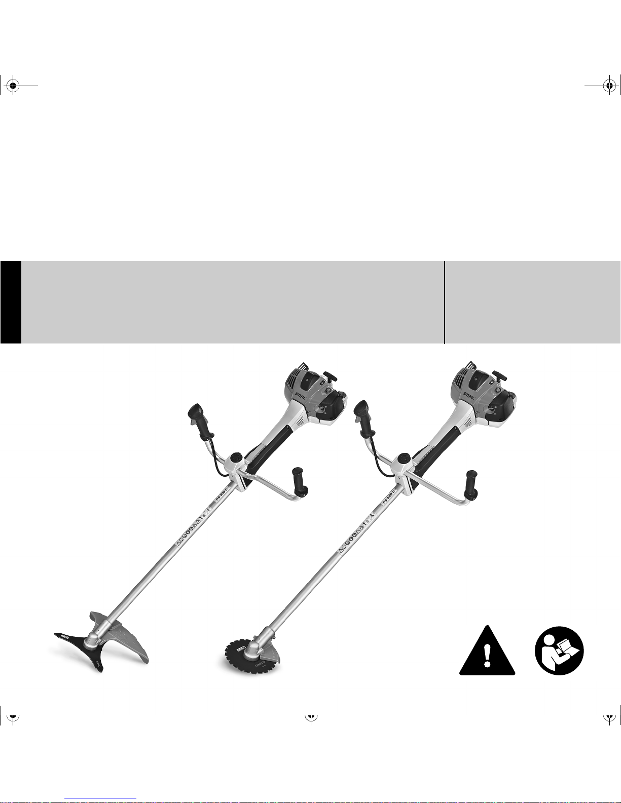
STIHL FS 510 C, 560 C
Instruction Manual
Notice d’emploi

G Instruction Manual
1 - 52
F Notice d’emploi
53 - 108

Original Instruction ManualPrinted on chlorine-free paper
Printing inks contain vegetable oils, paper can be recycled.
© ANDREAS STIHL AG & Co. KG, 2016
0458-772-8221-A. VA0.J16.
0000005287_011_GB
FS 510 C, FS 560 C
English
1
{
This instruction manual is protected by copyright. All rights reserved, especially the rights to reproduce, translate and process
with electronic systems.
Contents
Dear Customer,
Thank you for choosing a quality
engineered STIHL product.
It has been built using modern
production techniques and
comprehensive quality assurance.
Every effort has been made to ensure
your satisfaction and troublefree use of
the product.
Please contact your dealer or our sales
company if you have any queries
concerning this product.
Your
Dr. Nikolas Stihl
Guide to Using this Manual 2
Safety Precautions and Working
Techniques 2
Approved Combinations of Cutting
Attachment, Deflector, Limit Stop
and Harness 13
Mounting the Bike Handle 14
Adjusting the Throttle Cable 18
Mounting the Deflector 18
Mounting the Cutting Attachment 22
Fuel 27
Fueling 28
Fitting the Full Harness 29
Balancing the Machine 30
Starting / Stopping the Engine 30
Transporting the Unit 33
Operating Instructions 34
Air filter 35
Engine Management 36
M-Tronic 36
Winter Operation 36
Spark Plug 38
Engine Running Behavior 39
Storing the Machine 39
Sharpening Metal Cutting Blades 40
Maintaining the Mowing Head 40
Inspection and Maintenance by
User 41
Inspections and Maintenance by
Dealer 42
Maintenance and Care 44
Main Parts 46
Specifications 48
Maintenance and Repairs 49
Disposal 50
STIHL Limited Emission Control
Warranty Statement 50
FS 510 C, FS 560 C
English
2
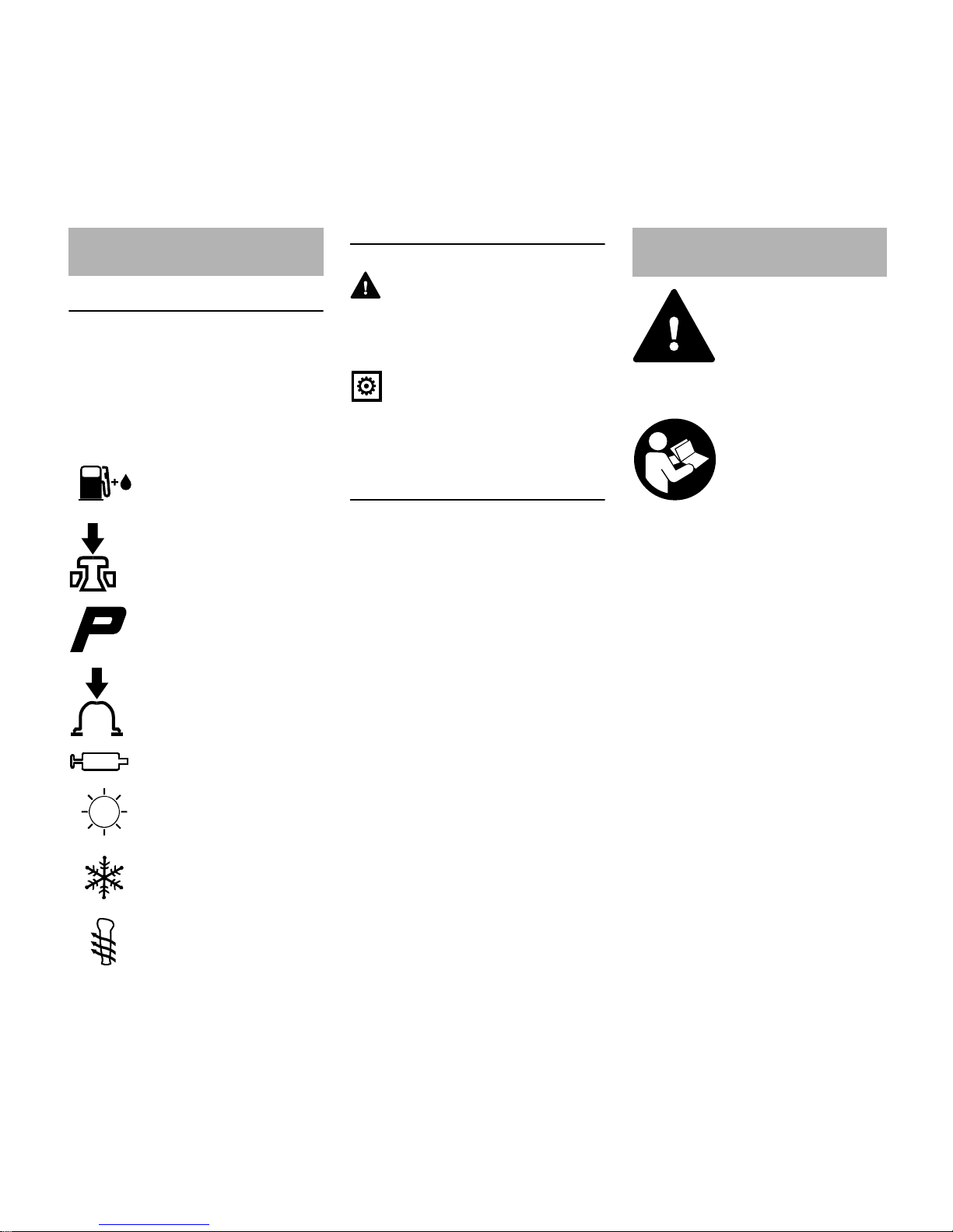
Pictograms
The meanings of the pictograms
attached to the machine are explained in
this manual.
Depending on the model concerned, the
following pictograms may be attached to
your machine.
Symbols in text
WARNING
Warning where there is a risk of an
accident or personal injury or serious
damage to property.
NOTICE
Caution where there is a risk of
damaging the machine or its individual
components.
Engineering improvements
STIHL's philosophy is to continually
improve all of its products. For this
reason we may modify the design,
engineering and appearance of our
products periodically.
Therefore, some changes, modifications
and improvements may not be covered
in this manual.
Observe all applicable local safety
regulations, standards and ordinances.
If you have not used this type of power
tool before: Have your dealer or other
experienced user show you how to
operate your machine or attend a
special course in its operation.
Minors should never be allowed to use a
power tool.
Keep bystanders, especially children,
and animals away from the work area.
When the power tool is not in use, shut it
off so that it does not endanger others.
Secure it against unauthorized use.
The user is responsible for avoiding
injury to third parties or damage to their
property.
Do not lend or rent your power tool
without the instruction manual. Be sure
that anyone using it understands the
information contained in this manual.
Guide to Using this Manual
Fuel tank; fuel mixture of
gasoline and engine oil
Operate decompression
valve
Manual fuel pump
Operate manual fuel
pump
Tube of grease
Intake air: Summer
operation
Intake air: Winter
operation
Handle heating
Safety Precautions and
Working Techniques
Some special safety precautions have to be
observed when working
with this power tool
because of the very high
speed of the cutting
attachment.
It is important that you
read the instruction manual before first use and
keep it in a safe place for
future reference. Nonobservance of the
instruction manual may
result in serious or even
fatal injury.
FS 510 C, FS 560 C
English
3
The use of noise emitting power tools
may be restricted to certain times by
national or local regulations.
To operate the power tool you must be
rested, in good physical condition and
mental health.
If you have any condition that might be
aggravated by strenuous work, check
with your doctor before operating a
power tool.
Persons with pacemakers only: The
ignition system of your power tool
produces an electromagnetic field of a
very low intensity. This field may
interfere with some pacemakers. STIHL
recommends that persons with
pacemakers consult their physician and
the pacemaker manufacturer to reduce
any health risk.
Do not operate the power tool if you are
under the influence of any substance
(drugs, alcohol) which might impair
vision, dexterity or judgment.
Depending on the cutting attachment
fitted, use your power tool only for
cutting grass, wild growth, shrubs,
scrub, bushes, small diameter trees and
similar materials.
Do not use your power tool for any other
purpose because of the increased risk of
accidents.
Only use cutting attachments and
accessories that are explicitly approved
for this power tool model by STIHL or
are technically identical. If you have any
questions in this respect, consult a
servicing dealer. Use only high quality
tools and accessories in order to avoid
the risk of accidents and damage to the
machine.
STIHL recommends the use of genuine
STIHL tools and accessories. They are
specifically designed to match the
product and meet your performance
requirements.
Never attempt to modify your machine in
any way since this may increase the risk
of personal injury. STIHL excludes all
liability for personal injury and damage
to property caused while using
unauthorized attachments.
Do not use a pressure washer to clean
the unit. The solid jet of water may
damage parts of the unit.
The deflector on this power tool cannot
protect the operator from all objects
thrown by the cutting attachment
(stones, glass, wire, etc.). Such objects
may ricochet and then hit the operator.
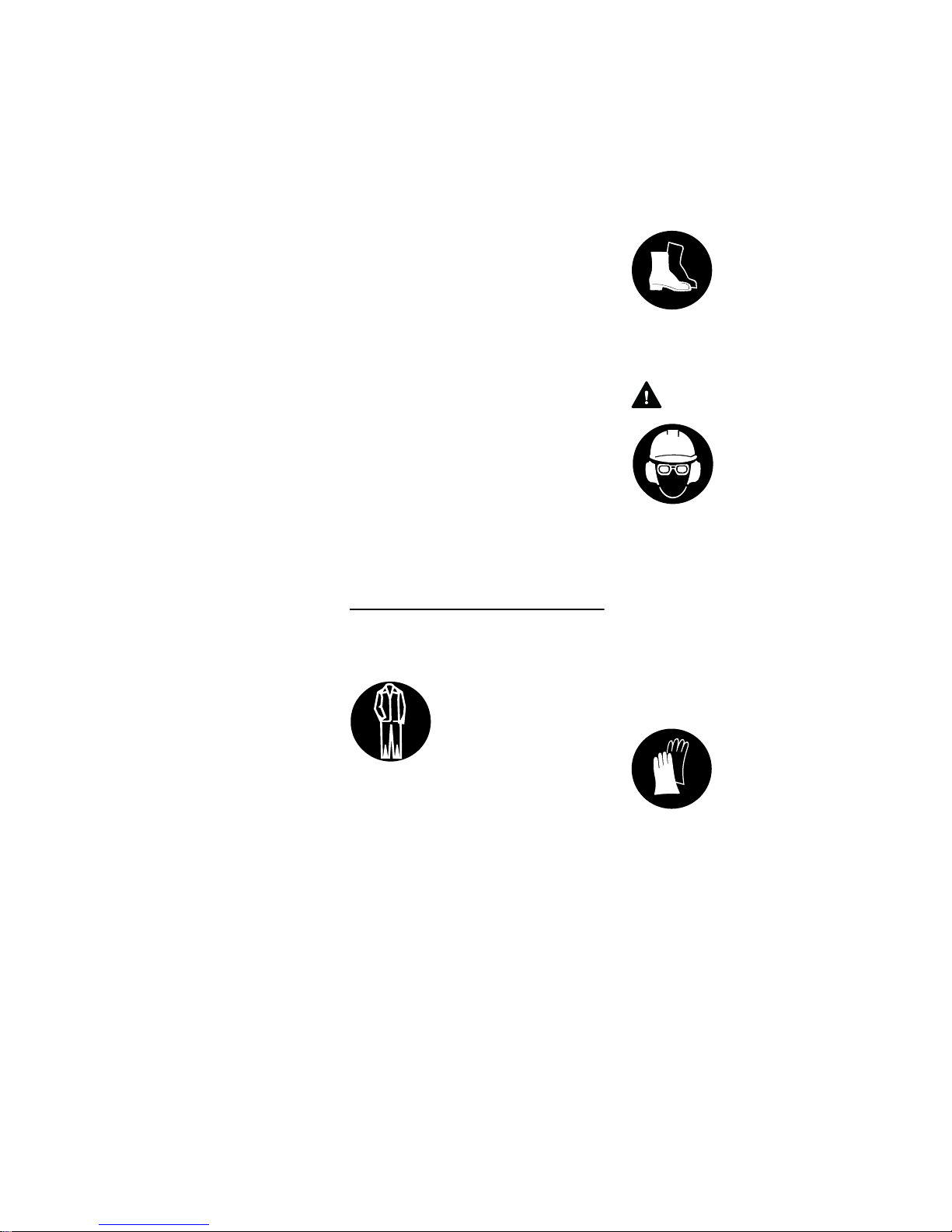
Clothing and Equipment
Wear proper protective clothing and
equipment.
Avoid clothing that could get caught on
branches or brush or moving parts of the
machine. Do not wear a scarf, necktie or
jewelry. Tie up and confine long hair
(e.g. with a hair net, cap, hard hat, etc.).
Sturdy shoes with non-slip soles may be
worn as an alternative only when using
mowing heads.
WARNING
Wear a face shield and make sure it is a
good fit. A face shield alone does not
provide adequate eye protection.
Wear hearing protection, e.g. earplugs
or ear muffs.
Wear a safety hard hat for thinning
operations, when working in high scrub
and where there is a danger of head
injuries from falling objects.
STIHL offers a comprehensive range of
personal protective clothing and
equipment.
Clothing must be sturdy
but allow complete freedom of movement. Wear
snug-fitting clothing, an
overall and jacket combination, do not wear a
work coat.
Wear steel-toed safety
boots with non-slip soles.
To reduce the risk of eye
injuries, wear snug-fitting
safety glasses in accordance with European
Standard EN 166. Make
sure the safety glasses
are a good fit.
Wear heavy-duty work
gloves made of durable
material (e.g. leather).
FS 510 C, FS 560 C
English
4
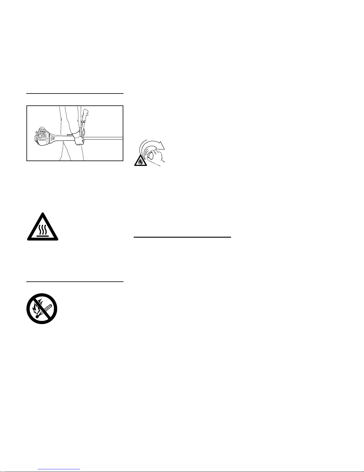
Transporting the Power Tool
Always stop the engine.
Carry the unit hanging from the shoulder
strap or properly balanced by the drive
tube. Fit transport guard on metal cutting
attachments to avoid the risk of injury
from blade contact
Transporting by vehicle: Properly secure
your power tool to prevent turnover, fuel
spillage and damage.
Fueling
Always shut off the engine before
refueling.
Do not fuel a hot engine – fuel may spill
and cause a fire.
Open the fuel cap carefully to allow any
pressure build-up in the tank to release
slowly and avoid fuel spillage.
Fuel your power tool only in wellventilated areas. If you spill fuel, wipe
the machine immediately – if fuel gets on
your clothing, change immediately.
This reduces the risk of unit vibrations
causing the fuel cap to loosen or come
off and spill quantities of fuel.
To reduce the risk of serious or fatal
burn injuries, check for fuel leakage. If
fuel leakage is found, do not start or run
the engine until leak is fixed.
Before Starting
Check that your power tool is properly
assembled and in good condition – refer
to appropriate chapters in the instruction
manual.
– Check the fuel system for leaks,
paying special attention to visible
parts such as the tank cap, hose
connections and the manual fuel
pump (on machines so equipped). If
there are any leaks or damage, do
not start the engine – risk of fire.
Have your machine repaired by a
servicing dealer before using it
again.
– Use only an approved combination
of cutting attachment, deflector,
handle and harness. All parts must
be assembled properly and
securely.
– The stop switch must move freely.
– Check smooth action of choke
knob, throttle trigger lockout and
throttle trigger – the throttle trigger
must return automatically to the idle
position. The choke knob must
spring back from the } position to
the run position F when the throttle
trigger lockout and throttle trigger
are squeezed.
– Check that the spark plug boot is
secure – a loose boot may cause
arcing that could ignite combustible
fumes and cause a fire.
– Check cutting tool or attachment for
correct and secure assembly and
good condition.
– Check protective devices (e.g.
deflector for cutting attachment,
rider plate) for damage or wear.
Always replace damaged parts. Do
not operate your machine with a
damaged deflector or worn rider
plate (lettering and arrows no longer
legible).
– Never attempt to modify the controls
or safety devices in any way.
To reduce the risk of serious burn injuries, avoid
touching hot parts of the
machine, including the
gearbox housing.
Gasoline is an extremely
flammable fuel. Keep
clear of naked flames. Do
not spill any fuel – do not
smoke.
002BA479 KN
After fueling, tighten
down the screw-type fuel
cap as securely as
possible.
FS 510 C, FS 560 C
English
5
– Keep the handles dry and clean –
free from oil and dirt – for safe
control of the power tool.
– Adjust the harness and handle(s) to
suit your height and reach. See
chapters on "Fitting the Harness"
and "Balancing the Machine".
To reduce the risk of accidents, do not
operate your power tool if it is damaged
or not properly assembled.
If you use a shoulder strap or full
harness: Practice removing and putting
down the power tool as you would in an
emergency. To avoid damage, do not
throw the power tool to the ground when
practicing.
Starting the Engine
Start the engine at least 3 meters from
the fueling spot, outdoors only.
Place the unit on firm ground in an open
area. Make sure you have good balance
and secure footing. Hold the unit
securely. The cutting attachment must
be clear of the ground and all other
obstructions because it may begin to run
when the engine starts.
Your power tool is a one-person unit. To
reduce the risk of injury from thrown
objects, do not allow other persons
within a radius of 15 meters of your own
position – even when starting.
To reduce the risk of fire, keep hot
exhaust gases and hot muffler away
from easily combustible materials (e.g.
wood chips, bark, dry grass, fuel).
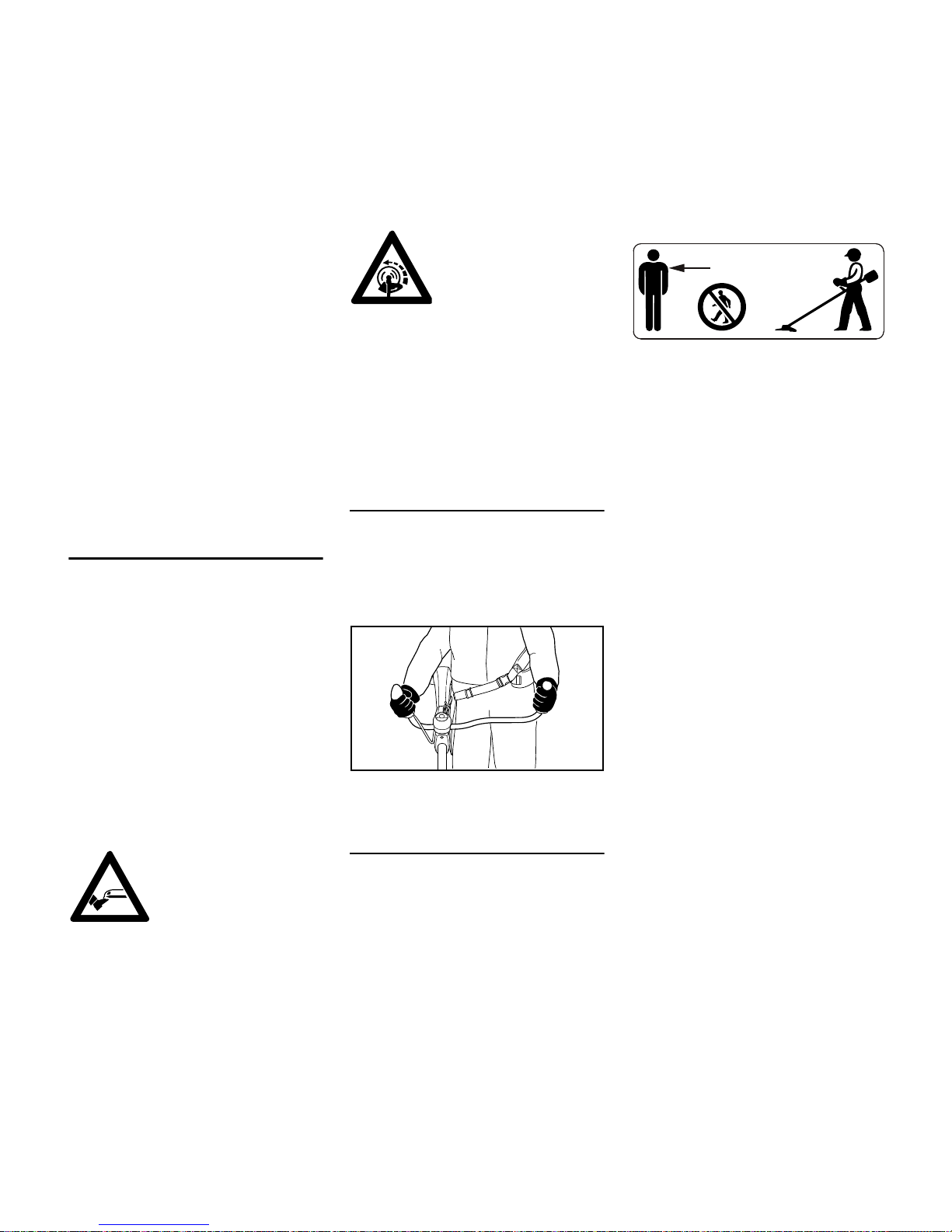
Holding and Controlling the Power Tool
Always hold the power tool firmly with
both hands on the handles.
Make sure you always have good
balance and secure footing.
Right handle on control handle, left hand
on left handle.
During Operation
Make sure you always have good
balance and secure footing.
In the event of imminent danger or in an
emergency, press the stop switch to
shut off the engine.
The cutting attachment may catch and
fling objects a great distance and cause
injury - therefore, do not allow any other
persons within a radius of 15 meters of
your own position. To reduce the risk of
damage to property, also maintain this
distance from other objects (vehicles,
windows). Even maintaining a distance
of 15 meters or more cannot exclude the
potential danger.
The correct engine idle speed is
important to ensure that the cutting
attachment stops rotating when you let
go of the throttle trigger. If the cutting
attachment continues to rotate when the
engine is idling, have the machine
checked by your servicing dealer. STIHL
recommends an authorized STIHL
servicing dealer.
Take special care in slippery conditions
(ice, wet ground, snow) – on slopes or
uneven ground.
Watch out for obstacles: Roots and tree
stumps which could cause you to trip or
stumble.
Always stand on the ground while
working, never on a ladder, work
platform or any other insecure support.
Be particularly alert and cautious when
wearing hearing protection because
your ability to hear warnings (shouts,
alarms, etc.) is restricted.
To reduce the risk of
injury, avoid contact with
the cutting attachment.
Do not drop start the
power tool – start the
engine as described in
the instruction manual.
Note that the cutting
attachment continues to
run for a short period
after you let go of the
throttle trigger – flywheel
effect.
002BA480 KN
15m (50ft)

FS 510 C, FS 560 C
English
6
To reduce the risk of accidents, take a
break in good time to avoid tiredness or
exhaustion.
Work calmly and carefully – in daylight
conditions and only when visibility is
good. Stay alert so as not to endanger
others.
To reduce the risk of serious or fatal
injury from breathing toxic fumes,
ensure proper ventilation when working
in trenches, hollows or other confined
locations.
To reduce the risk of accidents, stop
work immediately in the event of
nausea, headache, visual disturbances
(e.g. reduced field of vision), problems
with hearing, dizziness, deterioration in
ability to concentrate. Apart from other
possibilities, these symptoms may be
caused by an excessively high
concentration of exhaust gases in the
work area.
Operate your power tool so that it
produces a minimum of noise and
emissions – do not run the engine
unnecessarily, accelerate the engine
only when working.
To reduce the risk of fire, do not smoke
while operating or standing near your
power tool. Note that combustible fuel
vapor may escape from the fuel system.
The dusts, vapor and smoke produced
during operation may be dangerous to
health. If the work area is very dusty or
smoky, wear a respirator.
If your power tool is subjected to
unusually high loads for which it was not
designed (e.g. heavy impact or a fall),
always check that it is in good condition
before continuing work – see also
"Before Starting".
Check the fuel system in particular for
leaks and make sure the safety devices
are working properly. Do not continue
operating your power tool if it is
damaged. In case of doubt, consult your
servicing dealer.
Special care must be taken when
working in difficult, over-grown terrain.
When cutting high scrub, under bushes
and hedges: Keep cutting attachment at
a minimum height of 15 cm to avoid
harming small animals.
Always shut off the engine before
leaving the unit unattended.
Check the cutting attachment at regular
short intervals during operation or
immediately if there is a noticeable
change in cutting behavior:
– Turn off the engine. Hold the unit
firmly and wait for the cutting
attachment to come to a standstill.
– Check condition and tightness, look
for cracks.
– Check sharpness.
– Replace damaged or dull cutting
attachments immediately, even if
they have only superficial cracks.
Clean grass and plant residue off the
cutting attachment mounting at regular
intervals – remove any build up of
material from the cutting attachment and
deflector.
To reduce the risk of injury
, shut off the
engine before changing the cutting
attachment.
Do not continue using or attempt to
repair damaged or cracked cutting
attachments by welding, straightening or
modifying the shape (out of balance).
Your power tool produces
toxic exhaust fumes as
soon as the engine is
running. These fumes
may be colorless and
odorless and contain
unburned hydrocarbons
and benzol. Never run
the engine indoors or in
poorly ventilated locations, even if your model
is equipped with a catalytic converter.
To reduce the risk
of injury from
thrown objects,
never operate the
unit without the
proper deflector for
the type of cutting
attachment being
used.
Inspect the work area:
Stones, pieces of metal
or other solid objects may
be thrown more than 15
meters and cause personal injury or damage
the cutting attachment
and property (e.g. parked
vehicles, windows).
The gearbox becomes
hot during operation. To
reduce the risk of burn
injury, do not touch the
gearbox housing.

FS 510 C, FS 560 C
English
7
This may cause parts of the cutting
attachment to come off and hit the
operator or bystanders at high speed
and result in serious or fatal injuries.
When using mowing heads
Use only the deflector with properly
mounted line limiting blade to ensure the
mowing lines are automatically trimmed
to the approved length.
To reduce the risk of injury, always turn
off the engine before adjusting the nylon
line of manually adjustable mowing
heads
Using the unit with over-long nylon
cutting lines reduces the motor's
operating speed. The clutch then slips
continuously and this causes
overheating and damage to important
components (e.g. clutch, polymer
housing components) – and this can
increase the risk of injury from the
cutting attachment rotating while the
engine is idling.
Using metal cutting attachments
STIHL recommends the use of original
STIHL metal cutting attachments. They
are specifically designed to match your
model and meet your performance
requirements.
Metal cutting attachments rotate at very
high speed. The forces that occur act on
the machine, the attachment and the
material being cut.
Sharpen metal cutting attachments
regularly as specified.
Unevenly sharpened metal cutting
attachments cause out-of-balance
which can impose extremely high loads
on the machine and increase the risk of
breakage.
Dull or improperly sharpened cutting
edges can put a higher load on the
cutting attachment and increase the risk
of injury from cracked or broken parts.
Inspect metal cutting attachments for
cracks or warping after every contact
with hard objects (e.g. stones, rocks,
pieces of metal). To reduce the risk of
injury, remove burrs and other visible
build-ups of material (use a file) because
they may become detached and be
thrown at high speed during operation.
If a rotating metal cutting attachment
makes contact with a rock or other solid
object there is a risk of sparking which
may cause easily combustible material
to catch fire under certain
circumstances. Dry plants and scrub are
also easily combustible, especially in hot
and dry weather conditions. If there is a
risk of fire, do not use metal cutting
attachments near combustible
materials, dry plants or scrub. Always
contact your local forest authority for
information on a possible fire risk.
To reduce the above-mentioned risks
when using a metal cutting attachment,
never use a metal cutting attachment
with a diameter larger than specified. It
must not be too heavy. It must be
manufactured from materials of
adequate quality and its geometry must
be correct (shape, thickness).
To reduce the risk of injury, a metal
cutting attachment not manufactured by
STIHL must not be heavier, thicker,
have a different shape or a diameter
larger than the largest metal cutting
attachment approved by STIHL for this
power tool model.
Vibrations
Prolonged use of the power tool may
result in vibration-induced circulation
problems in the hands (whitefinger
disease).
No general recommendation can be
given for the length of usage because it
depends on several factors.
The period of usage is prolonged by:
– Hand protection (wearing warm
gloves)
– Work breaks
The period of usage is shortened by:
– Any personal tendency to suffer
from poor circulation (symptoms:
frequently cold fingers, tingling
sensations).
– Low outside temperatures.
– The force with which the handles
are held (a tight grip restricts
circulation).
Continual and regular users should
monitor closely the condition of their
hands and fingers. If any of the above
symptoms appear (e.g. tingling
sensation in fingers), seek medical
advice.
FS 510 C, FS 560 C
English
8
Maintenance and Repairs
Service the machine regularly. Do not
attempt any maintenance or repair work
not described in the instruction manual.
Have all other work performed by a
servicing dealer.
STIHL recommends that you have
servicing and repair work carried out
exclusively by an authorized STIHL
servicing dealer. STIHL dealers are
regularly given the opportunity to attend
training courses and are supplied with
the necessary technical information.
Only use high-quality replacement parts
in order to avoid the risk of accidents
and damage to the machine. If you have
any questions in this respect, consult a
servicing dealer.
STIHL recommends the use of original
STIHL replacement parts. They are
specifically designed to match your
model and meet your performance
requirements.
To reduce the risk of injury from
unintentional engine startup, always
shut off the engine and disconnect the
spark plug boot before performing any
repairs, maintenance or cleaning work. –
Exception: Carburetor and idle speed
adjustments.
Do not turn the engine over on the
starter with the spark plug boot or spark
plug removed since there is otherwise a
risk of fire from uncontained sparking.
To reduce the risk of fire, do not service
or store your machine near open flames.
Check the fuel filler cap for leaks at
regular intervals.
Use only a spark plug of the type
approved by STIHL and make sure it is
in good condition – see "Specifications".
Inspect the ignition lead (insulation in
good condition, secure connection).
Check the condition of the muffler.
To reduce the risk of fire and damage to
hearing, do not operate your machine if
the muffler is damaged or missing. –
Do not touch a hot muffler since burn
injury will result.
Vibration behavior is influenced by the
condition of the AV elements – check the
AV elements at regular intervals.
Maintenance, replacement, or repair of
the emission control devices and
systems may be performed by any
nonroad engine repair establishment or
individual. However, if you make a
warranty claim for a component which
has not been serviced or maintained
properly or if nonapproved replacement
parts were used, STIHL may deny
coverage.
For any maintenance please refer to the
maintenance chart and to the warranty
statement near the end of the instruction
manual.
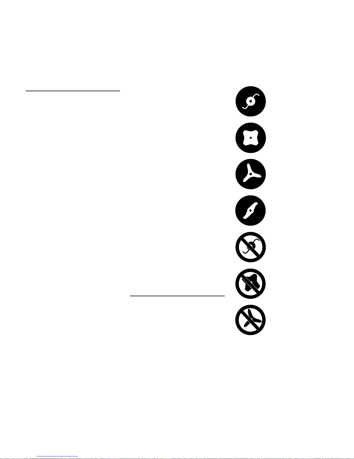
Symbols on Deflectors
An arrow on the deflector shows the
correct direction of rotation of the cutting
attachments.
Some of the following symbols are
applied to the outside of the deflector to
indicate the approved combination of
cutting attachment and deflector.
Deflector may be used
with mowing heads.
Deflector may be used
with grass cutting blades.
Deflector may be used
with brush knives.
Deflector may be used
with shredder blades.
Deflector must not be
used with mowing heads.
Deflector must not be
used with grass cutting
blades.
Deflector must not be
used with brush knives.
FS 510 C, FS 560 C
English
9
Harness
The harness is included with the
machine or available as a special
accessory.
N Use the harness.
N With the engine running, attach the
machine to the harness.
All cutting attachments must be used in
combination with a full harness with a
quick-release system.
Mowing Head with Nylon Line
Nylon line achieves a soft cut for edging
and trimming around trees, fence posts,
etc. – less risk of damaging tree bark.
The mowing head comes with an
instruction leaflet. Refill the mowing
head with nylon line as described in the
instruction leaflet.
WARNING
To reduce the risk of serious injury,
never use wire or metal-reinforced line in
place of the nylon line.
STIHL DuroCut
Check the wear limit marks!
If one of the wear limit marks imbedded
in the baseplate of the DuroCut
(exclamation marks) becomes visible,
do not continue using the mowing head
since it may otherwise be damaged.
Replace the worn baseplate.
The mowing head comes with
instruction leaflets. Equip the mowing
head only with nylon line as described in
the instruction leaflets.
WARNING
Never use wire in place of the nylon
mowing line – risk of injury.
STIHL Polycut Mowing Head with
Polymer Blades
For mowing unobstructed edges of
meadows (without posts, fences, trees
or similar obstacles).
Check the wear limit marks!
Deflector must not be
used with shredder
blades.
Deflector must not be
used with circular saw
blades.
002BA397 KN
000BA015 KN
681BA209 KN
FS 510 C, FS 560 C
English
10
If one of the wear limit marks on the
PolyCut mowing head is worn through
(arrow): Do not continue using the
mowing head. Install a new one. There
is otherwise a risk of injury from thrown
parts of the head.
It is important to follow the maintenance
instructions for the PolyCut mowing
head.
The PolyCut can also be equipped with
mowing line in place of the polymer
blades.
The mowing head comes with
instruction leaflets. Equip the mowing
head with polymers blades or nylon line
as described in the instruction leaflets.
WARNING
Never use wire in place of the nylon
mowing line – risk of injury.
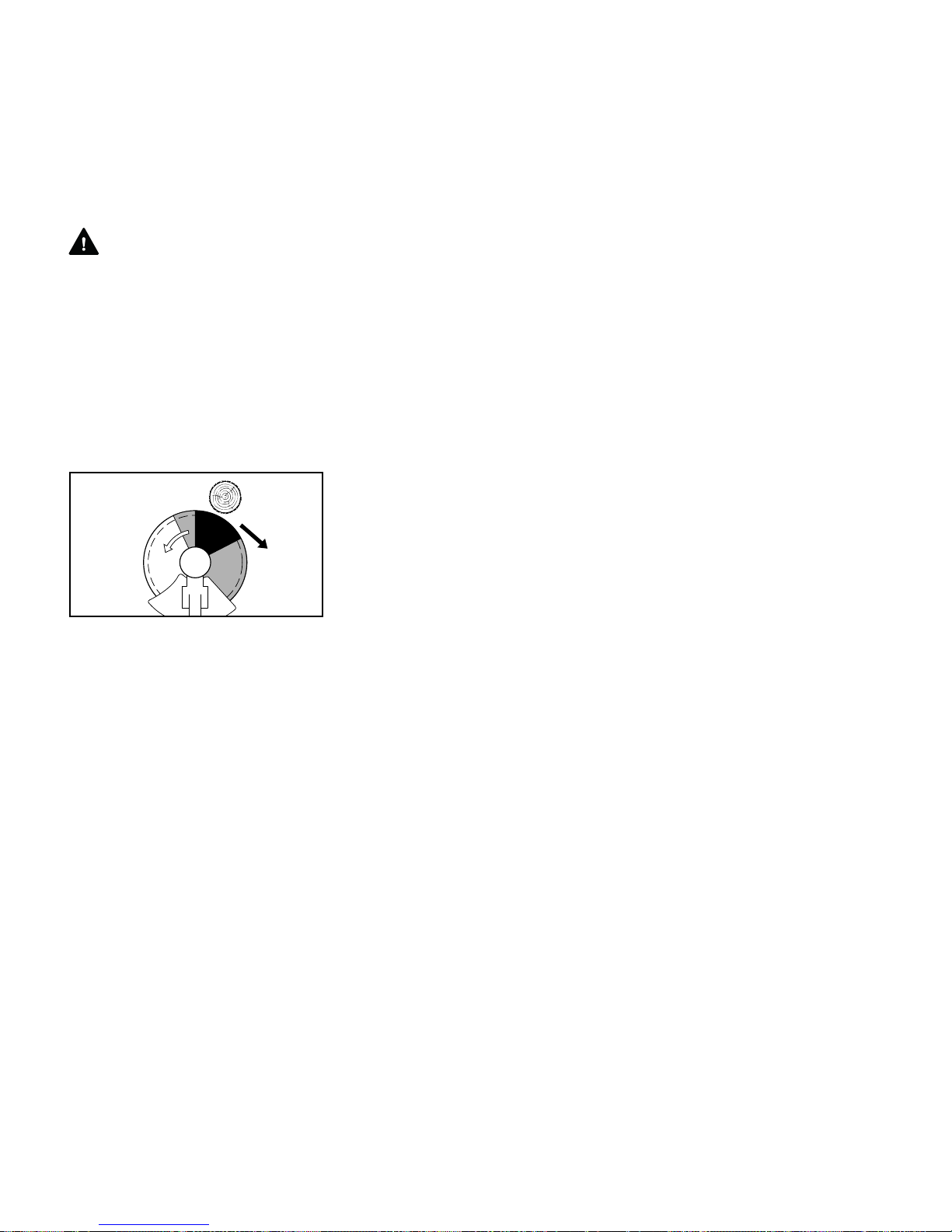
Risk of Kickout (Blade Thrust) with Metal
Cutting Attachments
WARNING
The risk of kickout is greatest when the
black area of the rotating cutting
attachment comes into contact with a
solid object.
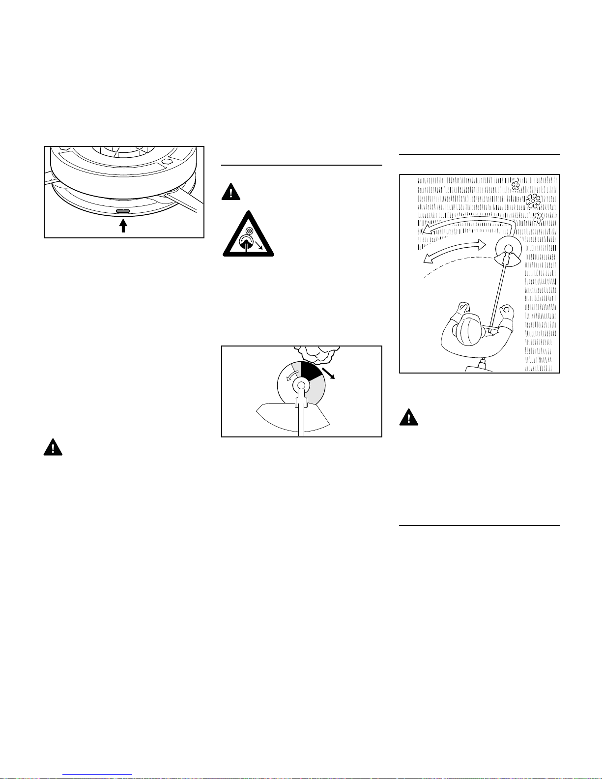
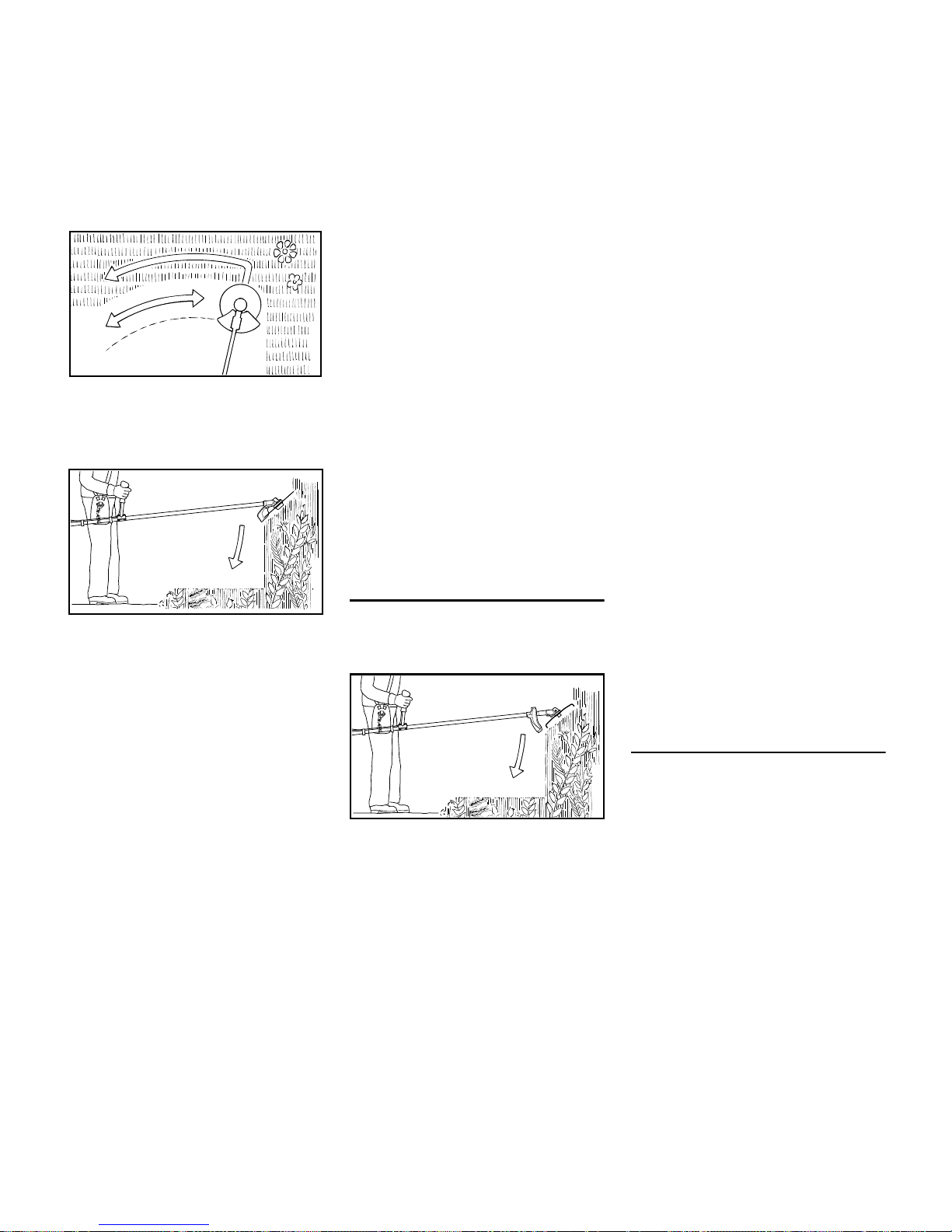
Grass Cutting Blade
Use for grass and weeds only – sweep
the brushcutter in an arc like a scythe.
WARNING
Improper use may damage the grass
cutting blade – risk of injury from thrown
parts.
Resharpen the grass cutting blade
according to instructions when it has
dulled noticeably.
Brush Knife
For cutting matted grass, wild growth
and scrub and thinning young stands
with a stem diameter of no more than
2 cm – do not cut thicker stems – risk of
accidents.
002BA396 KN
When using metal cutting attachments there is
a risk of kickout when the
rotating blade comes into
contact with a solid object
such as a tree trunk,
branch, tree stump, rock
or similar. The machine is
thrown to the right or to
the rear – opposite to the
attachment's direction of
rotation.
002BA135 KN
000BA020 KN
FS 510 C, FS 560 C
English
11
Use the brushcutter like a scythe (sweep
it to the right and left) at ground level
when cutting grass and thinning young
stands.
To cut wild growth and scrub, lower the
brush knife down onto the growth to
achieve a shredding effect – always
keep the cutting attachment below hip
level during this process.
Exercise extreme caution when using
this method of cutting. The higher the
cutting attachment is off the ground, the
greater the risk of injury from cuttings
being thrown sideways.
Warning! Improper use of a brush knife
may cause it to crack, chip or shatter –
risk of injury from thrown parts.
To reduce the risk of injury it is essential
to take the following precautions:
– Avoid contact with stones, rocks,
pieces of metal and other solid
foreign objects.
– Never cut wood or shrubs with a
stem diameter of more than 2 cm –
use a circular saw blade for such
work.
– Inspect the brush knife at regular
short intervals for signs of damage.
Do not continue working with a
damaged brush knife.
– Resharpen the brush knife regularly
and whenever it has dulled
noticeably, and have it balanced if
necessary (STIHL recommends a
STIHL servicing dealer).
Shredder Blade
Suitable for thinning and shredding
tough, matted grass and scrub.
To cut wild growth and scrub, lower the
shredder blade down onto the growth to
achieve a shredding effect – always
keep the cutting attachment below hip
level during this process.
Exercise extreme caution when using
this method of cutting. The higher the
cutting attachment is off the ground, the
greater the risk of injury from cuttings
being thrown sideways.
Warning! Improper use may damage the
shredder blade – risk of injury from
thrown parts.
To reduce the risk of injury it is essential
to take the following precautions:
– Avoid contact with stones, rocks,
pieces of metal and other solid
foreign objects.
– Never cut wood or shrubs with a
stem diameter of more than 2 cm –
use a circular saw blade for such
work.
– Inspect the shredder blade at
regular short intervals for signs of
damage. Do not continue working
with a damaged shredder blade.
– Resharpen the shredder blade
regularly and whenever it has dulled
noticeably, and have it balanced if
necessary (STIHL recommends a
STIHL servicing dealer).
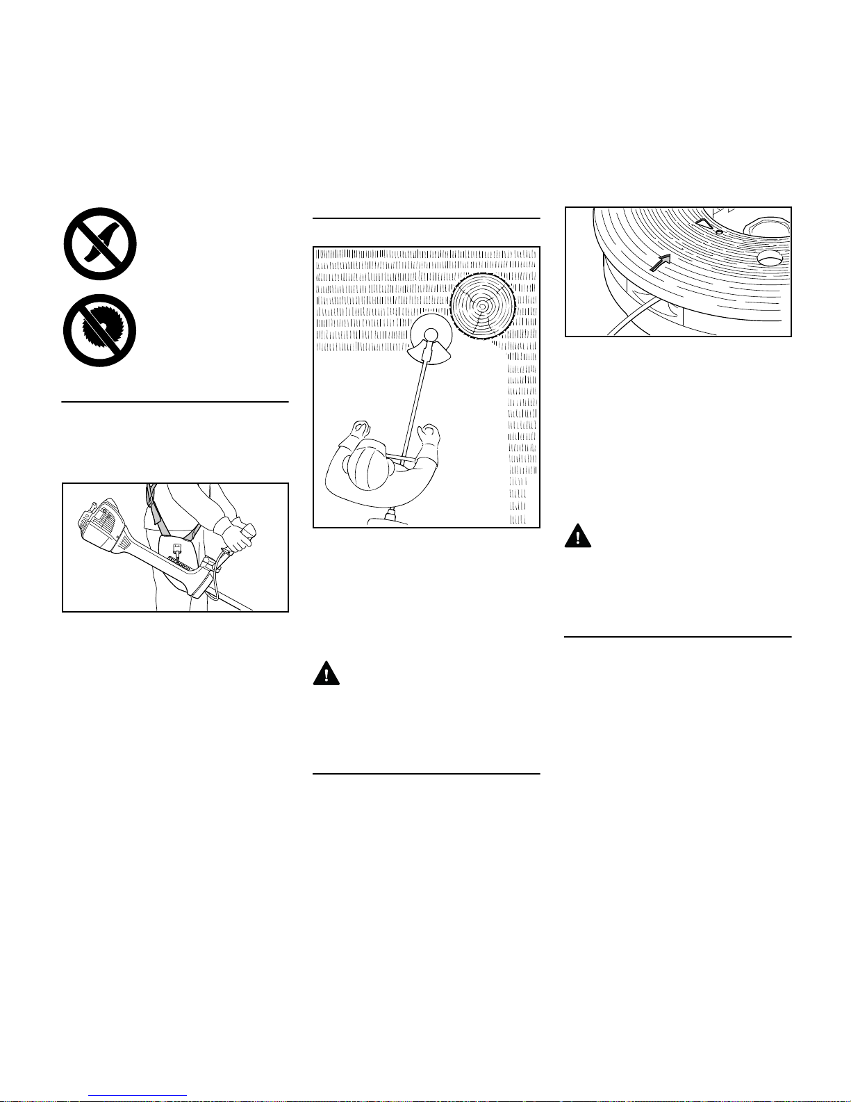
Circular Saw Blade
Suitable for cutting shrubs and trees with
a maximum stem diameter of 7 cm.
Before starting the cut, accelerate the
engine up to full throttle. Perform cut
with uniform pressure.
Use circular saw blades only with a
matching limit stop of the correct
diameter.
002BA355 KN
002BA509 KN
002BA210 KN
FS 510 C, FS 560 C
English
12
WARNING
To reduce the risk of blade damage,
avoid contact with stones and the
ground. Resharpen the blade properly in
good time – dull teeth may result in the
blade cracking and shattering and
causing serious injury.
When felling, maintain a distance of at
least two tree lengths from the next
felling site.
Risk of kickout
The risk of kickout is highest in the black
area of the blade: Do not use this area of
the circular saw blade for cutting.
There is also a risk of kickout when
using the lighter shaded areas of the
blade: These areas of the blade should
only be used by experienced operators
with specialized training.
STIHL recommends that you use the
non-shaded area of the circular saw
blade. Always start the cut with this area
of the blade.
002BA449 KN

FS 510 C, FS 560 C
English
13
Approved Combinations of Cutting Attachment, Deflector, Limit Stop and Harness
Cutting Attachment Deflector, Limit Stop Harness
10
11
12
13
17
16
15
14
7
9
0000-GXX-0377-A0
5
8
6
18
2
1
4
3
FS 510 C, FS 560 C
English
14
Approved Combinations
Select correct combination from the
table according to the cutting
attachment you intend to use.
WARNING
For safety reasons only the cutting
attachments and deflectors or limit stops
shown in each row of the table may be
used together. No other combinations
are permitted because of the risk of
accidents.
Cutting Attachments
Mowing heads
1 STIHL AutoCut 40-4
2 STIHL AutoCut 56-2
3 STIHL TrimCut 51-2
4 STIHL DuroCut 40-4
5 STIHL PolyCut 41-3
Metal cutting attachments
6 Grass cutting blade 255-8
(255 mm dia.)
7 Grass cutting blade 250-40 Spezial
(250 mm dia.)
8 Brush knife 305-2 Spezial
(305 mm dia.)
9 Brush knife 350-3
(350 mm dia.)
10 Shredder blade 320-2
(320 mm dia.)
11 Scratcher tooth circular saw blade
225
(225 mm dia.)
12 Chisel tooth circular saw blade 225
(225 mm dia.)
13 Carbide tipped circular saw blade
225
(225 mm dia.)
WARNING
Non-metal grass cutting blades, brush
knives, shredder blades and circular
saw blades are not approved.
Deflectors, Limit Stop
14 Deflector for mowing heads
15 Deflector for metal cutting
attachments, items 6 to 9
16 Deflector for shredder blade
17 Limit stop for circular saw blades
Harness
18 Full harness must be used
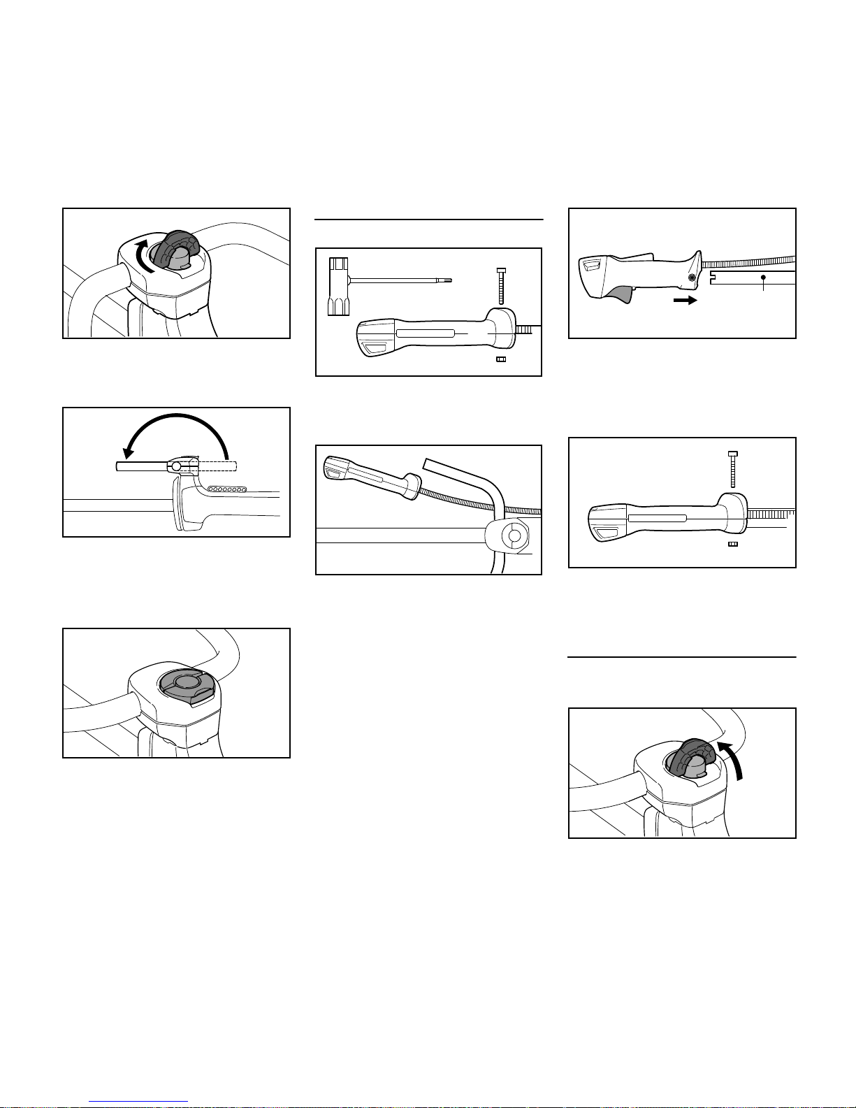
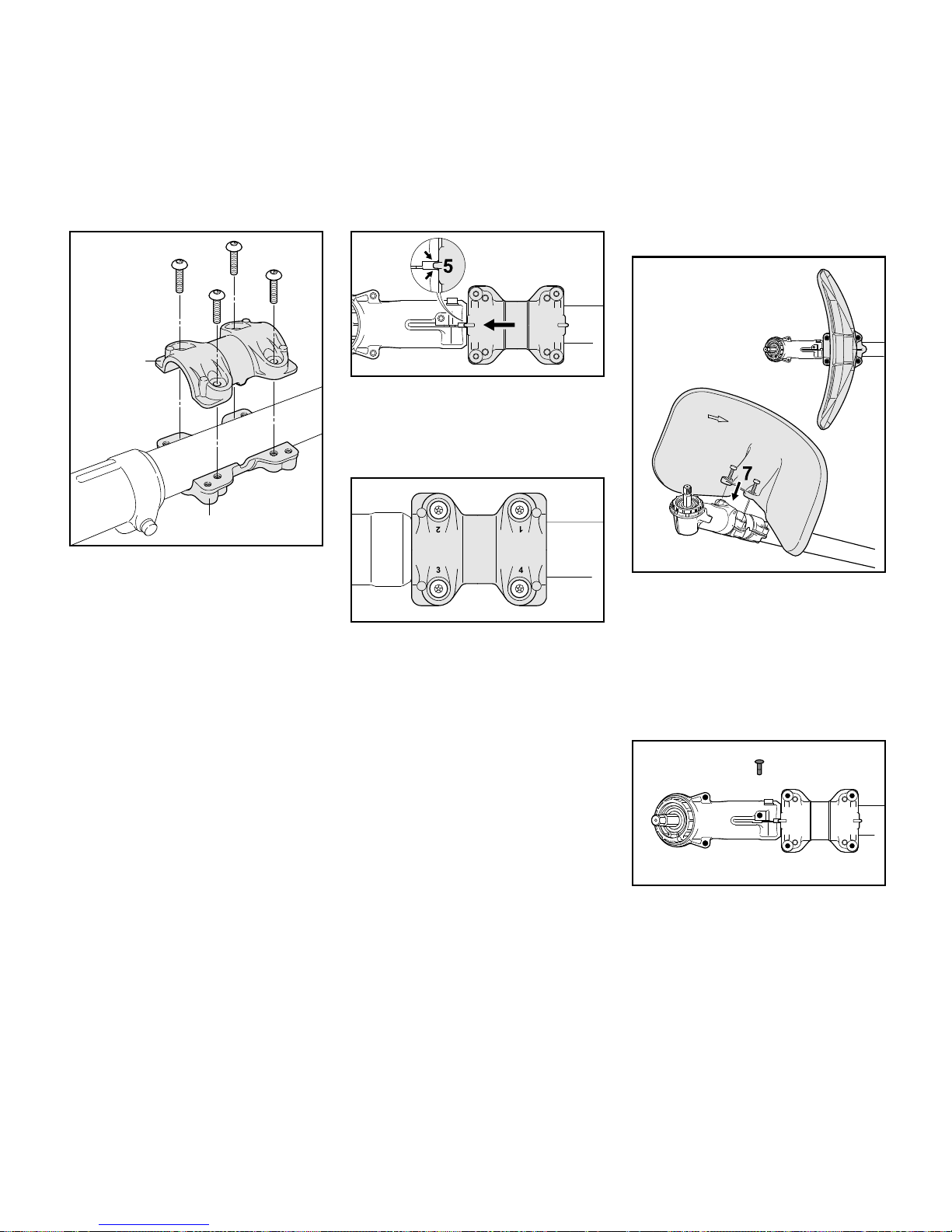
Mounting Bike Handle with Swiveling
Handle Support
Do not rotate the control handle (1)
between unpacking and mounting it on
the handlebar; see also chapter on
"Adjusting the Throttle Cable".
The brushcutter is available with two
different handlebars:
2 Handlebar for machines used
primarily for mowing, brushcutting
and shredding, but also for
occasional sawing.
Mounting the Bike Handle
1
3BA003 KN
3BA004 KN
4
2
FS 510 C, FS 560 C
English
15
3 Handlebar for machines used
mainly for sawing, but also for
mowing and brushcutting.
The machine is supplied with the clamp
moldings (4) mounted on the handlebars
(2, 3).
N Do not change the position of the
clamp moldings on the handlebar
until it is mounted on the handle
support.
The mounting procedure is the same for
both types of handlebar. Therefore, the
following description only shows
handlebar (2).
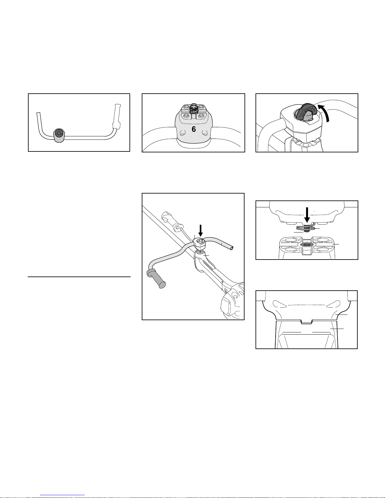
Mounting the Handlebar
Assembly of the swivelling handle
support involves equipping the clamp
moldings with a spring and mounting
them on the handle support.
N Use the spring (5) from the parts kit
supplied with the machine.
N Push the spring (5) into the lower
clamp molding (6).
N Position the clamp moldings (4) with
handlebar (2) on the handle support
(7).
N Do not turn the handlebar in the
clamp moldings.
N Raise the grip of the wing screw (8)
to the upright position.
N Rotate the wing screw
counterclockwise and tighten it only
moderately.
N Position wing screw (8) in threaded
insert in handle support (7) – against
pressure of spring (5).
N Position the clamp moldings so that
the tabs (9) on the lower clamp
molding (6) line up with the slots
(10) in the handle support (7).
2BA001 KN
4
3
3BA005 KN
5
4900BA002 KN
7
2
4
8
3BA007 KN
5
8
3BA008 KN
7
6
10
7
9
3BA0009 KN
FS 510 C, FS 560 C
English
16
N Rotate wing screw clockwise until
the lower clamp molding (6) butts
against the handle support (7).
N Swing the handebar (2) forwards
through 180°.
N Only tighten the wing screw
moderately.
N Fold the grip of the wing screw down
so that it is flush.
Mounting the Control Handle
N Take out the screw (11) and remove
the nut (12) from the control handle
(1).
N Hold the control handle in front of
the right-hand end of the handlebar
so that the throttle cable (13) is on
the inboard side of the handlebar
(2).
N Push the control handle (1) in this
position onto the end of the
handlebar (2) until the holes (15)
line up – throttle trigger (14) facing
down.
N Fit the nut (12) in the control handle,
insert the screw (11) and tighten it
down firmly.
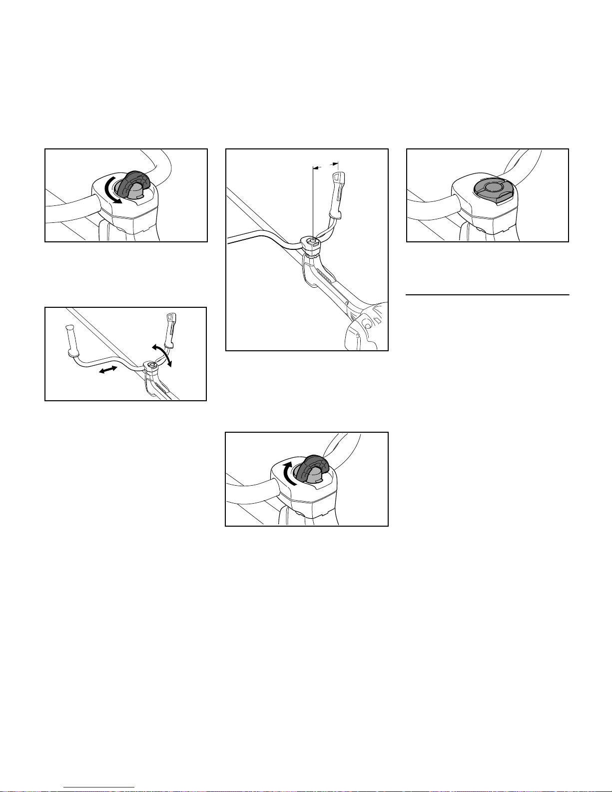
Adjusting the Handlebar
Opening the wing screw
N Raise the grip of the wing screw to
the upright position.
7
6
3BA010 KN
2
4900BA003 KN
4900BA004 KN
11
12
1
002BA451 KN
13
2
4900BA005 KN
14
15
15
2
4900BA007 KN
1
11
12
4900BA008 KN
4900BA009 KN
FS 510 C, FS 560 C
English
17
N Turn the wing screw
counterclockwise until the handle
support can be moved.
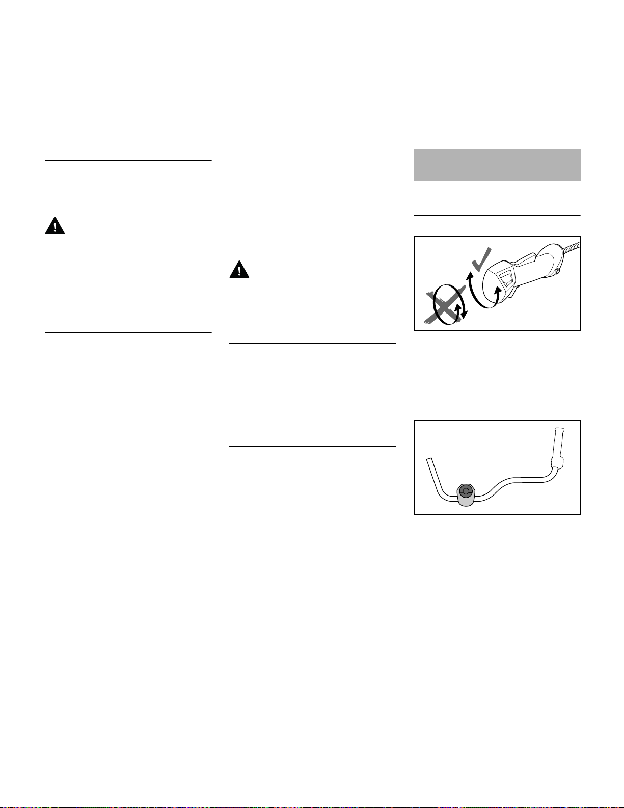
Lining up the handlebar
N Move the handlebar to the required
position.
N Position the handlebar (2) so that
distance A is about 7 in (17 cm).
Do not clamp the curved part of the
handlebar.
Closing the wing screw
N Rotate the wing screw clockwise
until it becomes difficult to turn.
N Tighten down the wing screw firmly.
N Fold the grip of the wing screw down
so that it is flush.
Checking the Throttle Cable
N After mounting the control handle,
check the throttle cable – see
chapter on "Adjusting the Throttle
Cable".
4900BA010 KN
4900BA011 KN
4900BA012 KN
2
A
4900BA013 KN
4900BA014 KN
FS 510 C, FS 560 C
English
18
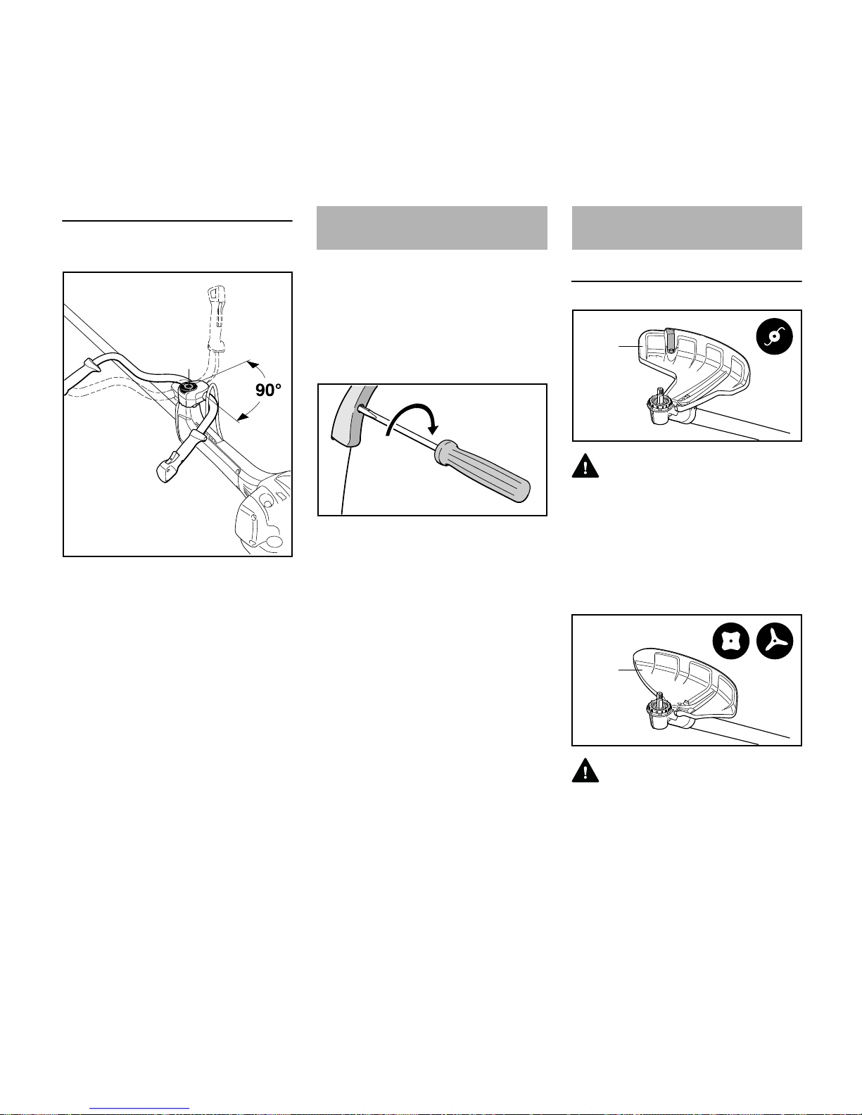
Swiveling the Handlebar
Transport position
N Loosen the wing screw (8) and
unscrew it until the handlebar (2)
can be turned clockwise.
N Turn the handlebar 90° and then
swing the handles down.
N Tighten down the wing screw (8)
firmly.
Working position
N Reverse the sequence described
above to swing the handles up and
turn the handlebar
counterclockwise.
It may be necessary to correct the
adjustment of the throttle cable after
assembling the machine or after a
prolonged period of operation.
Adjust the throttle cable only when the
unit is completely and properly
assembled.
N Set the throttle trigger to the full
throttle position.
N Carefully rotate the screw in the
throttle trigger in the direction of the
arrow until you feel initial resistance.
Then rotate it another half turn in the
same direction.
Use the Right Deflector
WARNING
Deflector (1) is approved for mowing
heads only and must therefore be
mounted before fitting a mowing head.
Recommendation: Use mowing heads
with a grass shield on the gearbox, see
chapters on "Mounting the Deflector" /
"Mounting the Grass Shield".
WARNING
Deflector (2) is approved for grass
cutting blades and brush knives only and
must therefore be mounted before fitting
a grass cutting blade or brush knife.
4900BA015 KN
2
8
Adjusting the Throttle Cable
002BA655 KN
Mounting the Deflector
1
002BA461 KN
2
002BA462 KN
FS 510 C, FS 560 C
English
19
Recommendation: Use grass cutting
blades with a grass shield on the
gearbox, see chapters on "Mounting the
Deflector" / "Mounting the Grass Shield".
WARNING
Deflector (3) is approved for shredder
blades only and must therefore be
mounted before fitting a shredder blade,
see chapter on "Mounting the Deflector".
WARNING
Stop (4) is approved for circular saw
blades only and must therefore be
mounted before fitting a circular saw
blade.
Mounting the Deflector
Deflectors (1, 2 and 4) are mounted to
the gearbox in the same way.
N Remove dirt from joints on gearbox
and deflector – make sure that no
dirt gets into the screw holes in the
gearbox – see section on "Plugs".
N Place the deflector on the gearbox
(5).
N Insert the screws (6) and tighten
them down firmly.
Mounting shredder deflector
Owing to the high loads on the shredder
deflector (3) and country-specific
regulations on the use of the machine for
shredding, the deflector must be
properly mounted to the machine.
A special screwdriver bit is required to
mount this deflector. The bit is available
only from specialist retailers. It has a
special drive for rotating the screws and
only allows the screws to be tightened.
Once tightened, the screws can no
longer be loosened – not even with the
special tool.
STIHL therefore recommends: Have the
shredder deflector mounted by your
STIHL dealer.
A "shredder deflector mounting kit" is
available as a special accessory for
retrofitting machines with a shredder
deflector. Depending on the machine's
original equipment, a "shredder blade
retrofit kit" may also be needed for the
conversion. Neither of these kits include
the shredder blade – it must be ordered
separately.
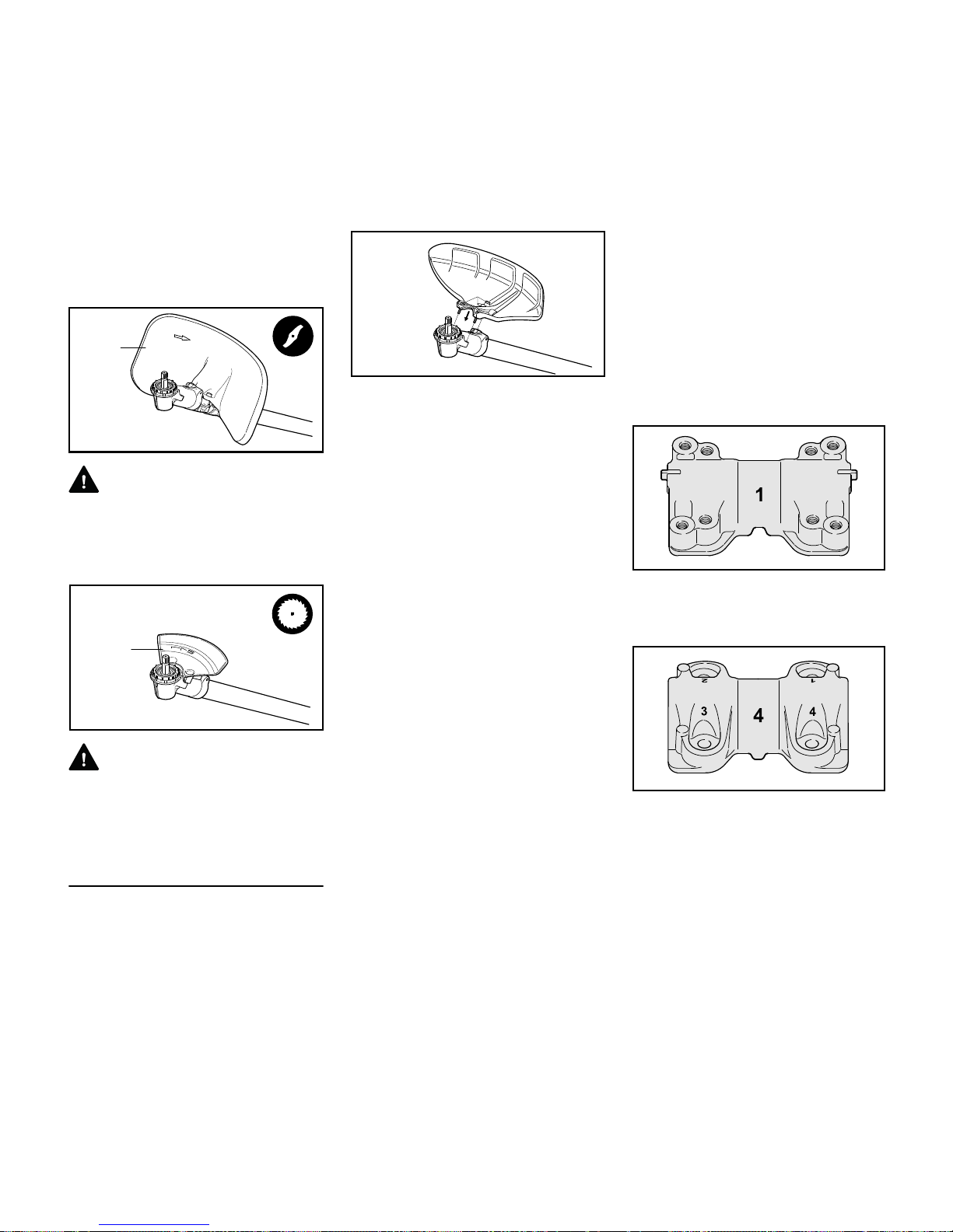
The "shredder blade retrofit kit" contains
clamps which butt against the gearbox
and have to be secured to the drive tube.
The kit also contains the shredder
deflector which is mounted to the
clamps.
– Installing the clamps
– Lower clamp (1): Identified by two
lugs (2) on its longitudinal axis, eight
tapped holes and a lateral notch (3).
– Upper clamp (4): Identified by holes
marked 1 to 4 and a lateral lug (5).
3
002BA463 KN
4
002BA464 KN
5
6
002BA465 KN
002BA495 KN
3
2
2
002BA496 KN
5
FS 510 C, FS 560 C
English
20
N Position the lower clamp (1) against
the underside of the drive tube next
to the gearbox.
N Position the upper clamp (4) on the
drive tube so that the lug (5)
engages the notch (3).
N Hold both clamps steady in this
position.
N Insert a screw into the hole marked
1 on the upper clamp (4) and wind it
only a few turns into the lower clamp
(1).
N Insert a screw in each of the holes
marked 2, 3 and 4 and wind them
only a few turns into the lower
clamp.
N Slide the clamps up against the
gearbox and engage the lug (5) in
the gearbox gap (arrows).
N Hold both clamps in this position.
N Screw home the screws in holes 1
and 2 as far as stop.
N Tighten down the screws in holes 1
and 2 to a torque of 8 Nm.
N Screw home the screws in holes 3
and 4 in that order and tighten them
down to a torque of 8 Nm.
– Mounting the shredder deflector
N Position the shredder deflector on
the lower clamp with its concave
side facing the gearbox (6).
N Insert the screws (7) and tighten
them down firmly.
– Plugs
Plugs (9) are available as special
accessories to help prevent dirt getting
into the unused tapped holes for the
deflector in the gearbox (6) and clamps
(8).
5
3
002BA497 KN
1
4
002BA498 KN
002BA499 KN
6
002BA500 KN
002BA466 KN
8
9
6
FS 510 C, FS 560 C
English
21
Four plugs (9) are supplied with the
shredder deflector.
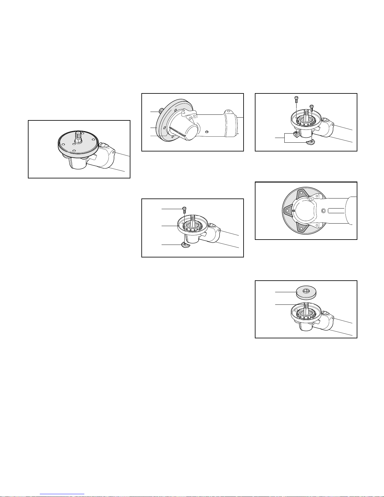
Fitting the grass shield
A grass shield is mounted to the gearbox
when using mowing heads and grass
cutting blades. It greatly reduces the
amount of grass, plant residue, etc. that
wraps itself around the gearbox and
cutting attachment.
Machines which have a mowing head or
grass cutting blade as original
equipment are supplied with a grass
shield. A "grass shield kit" is available as
a special accessory for retrofitting to
machines.
N Install the grass shield before
mounting the deflector – if
necessary, remove the deflector
that is already fitted on the gearbox.
N Hold the gearbox so that the shaft
(1) faces up.
N Place the grass shield (2) on the
gearbox so that the middle hole is in
line with the rib (3).
N Hold one of the three retainers (4)
against the gearbox and grass
shield so that the hole in the retainer
lines up with the middle hole.
N Insert the screw (5) in the retainer
and tighten it down only moderately
so that the grass shield (2) can still
be rotated on the gearbox.
N Fit the other two retainers (4) on the
gearbox and tighten down the
screws only moderately.
N Align the grass shield so that the
center of the front retainer is in line
with the rib on the gearbox.
N Tighten down the screws firmly.
N Fit the 60-mm diameter thrust plate
(5) on the shaft (1).
002BA501 KN
002BA502 KN
1
2
3
002BA503 KN
4
2
5
002BA504 KN
4
002BA512 KN
002BA505 KN
5
1
FS 510 C, FS 560 C
English
22
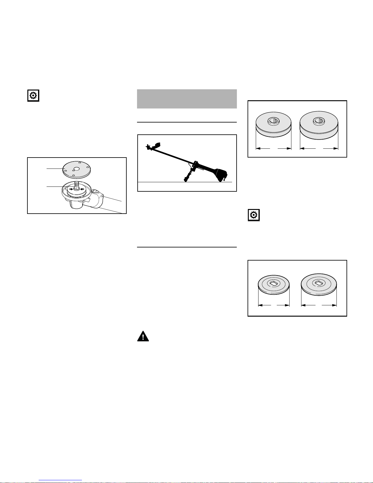
NOTICE
Only use the 60-mm diameter thrust
plate. The 65-mm diameter thrust plate
is too big and must not be used – see
chapters "Mounting the Cutting
Attachment" / "Mounting the Mowing
Head" / "Mounting Grass Cutting
Blades".
N Place the guard washer (6) on the
thrust washer – the whole collar
(arrows) on the shaft (1) must be
visible.
Placing power tool on the ground
N Shut off the engine.
N Lay your power tool on its back so
that the cutting attachment
mounting face is pointing up.
Mounting Hardware for Cutting
Attachment
The mounting hardware supplied
depends on the cutting attachment that
comes as original equipment with the
new machine.
The appropriate deflectors and
mounting hardware are available as
special accessories for subsequently
equipping the machine with different
cutting attachments – see chapter on
"Special Accessories".
WARNING
Always use and assemble the cutting
attachment mounting hardware as
described in the chapter on "Mounting
the Cutting Attachment".
Thrust plate
– 60 mm (2.4 in) diameter (A) version
for mounting mowing heads and
grass cutting blades
– 65 mm (2.6 in) diameter (A) version
for mounting brush knives, shredder
blades and circular saw blades
NOTICE
The thrust plate is necessary for
mounting all cutting attachments to the
gearbox.
Thrust washers
– 60 mm (2.4 in) diameter (A) version
for mounting grass cutting blades
and circular saw blades
– 70 mm (2.8 in) diameter (A) version
for mounting brush knives and
shredder blades
002BA506 KN
6
1
Mounting the Cutting
Attachment
002BA406 KN
681BA188 KN
A
A
681BA189 KN
A
A
FS 510 C, FS 560 C
English
23
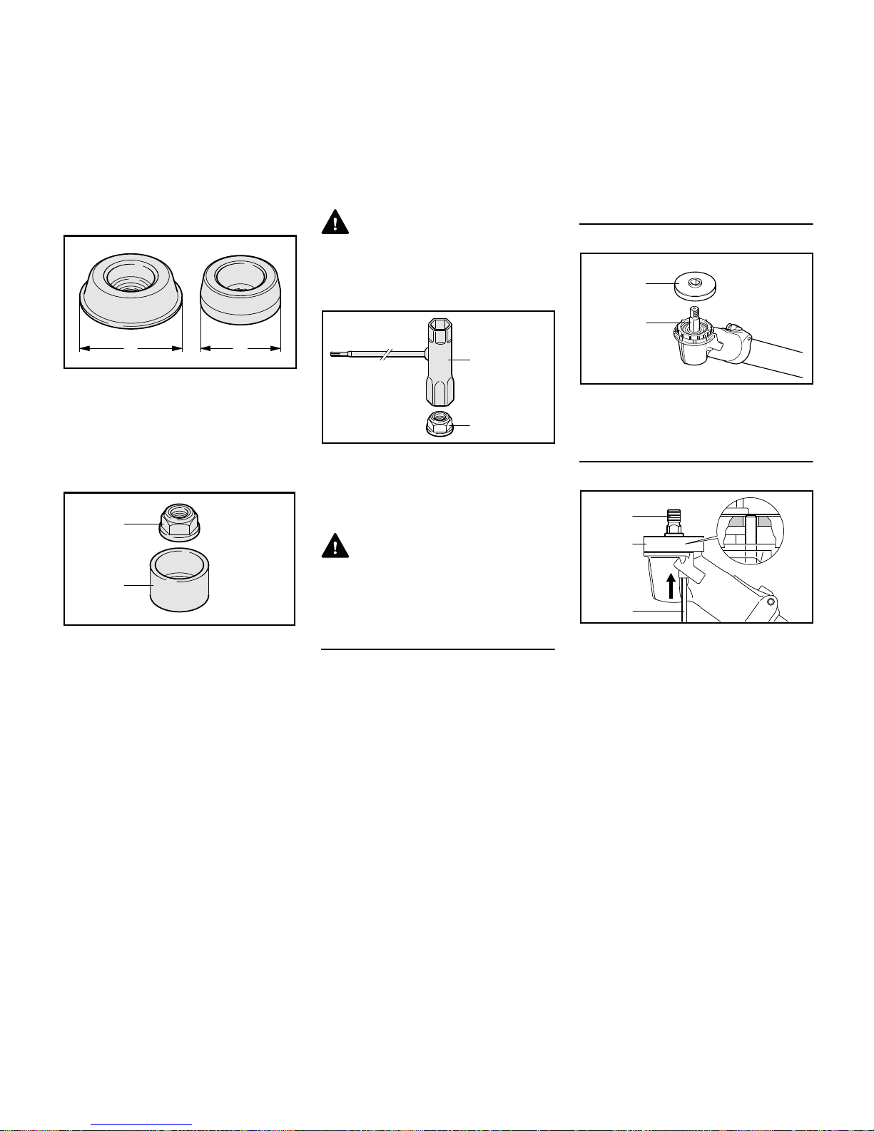
Rider plates, guard ring and nut
– Approximately 80 mm (3.2 in)
diameter (A) rider plate (1) for
grass cutting blades
– Approximately 63 mm (2.5 in)
diameter (A) rider plate (2) for
circular saw blades
– Guard ring (3) for brush knives and
shredder blades.
Both these parts have the same
function:
– Nut (4) and thread on shaft are
protected against wear.
– Ground contact with metal cutting
attachment is minimized.
– Rider plate allows cutting
attachment to glide along close to
ground.
WARNING
Always replace a worn rider plate and
guard ring in good time.
Nut and combination wrench
Metal cutting attachments are mounted
to the gearbox with the nut (4).
N Loosen and tighten the nut (4) with
the combination wrench (5).
WARNING
If the mounting nut has become too
loose, fit a new one.
Cleaning the Gearbox and Cutting
Attachment Mounting Hardware
Clean the gearbox, the area surrounding
it, inside the grass shield and the cutting
attachment mounting hardware at
regular intervals. Also check for
contamination when changing the
cutting attachment and clean thoroughly
if necessary.
N Remove all cutting attachment
mounting hardware from the
gearbox for this purpose.
Fitting the Thrust Plate
N Slip the thrust plate (1) over the
shaft (2).
Block the shaft.
The shaft (2) must be blocked to install
and remove cutting attachments.
The shaft (2) can be blocked only if the
thrust plate (1) is properly fitted – the
stop pin (3) has to engage the thrust
plate.
N Insert the stop pin (3) in the bore in
the gearbox – apply slight pressure.
N Rotate shaft or cutting attachment
until the stop pin slips into position
and blocks the shaft.
The stop pin is held in position in the
gearbox by a rubber element.
681BA190 KN
A
A
681BA191 KN
4
3
4
681BA192 KN
5
002BA467 KN
1
2
002BA507 KN
1
2
3
FS 510 C, FS 560 C
English
24
N Fit or remove the cutting attachment
– see chapter on "Mounting the
Cutting Attachment".
N Remove the stop pin.
NOTICE
Always remove the stop pin used to
block the shaft since the drive train will
otherwise be damaged when the engine
runs.
Mounting the cutting attachment
WARNING
Use a deflector that matches the cutting
attachment – see "Mounting the
Deflector".
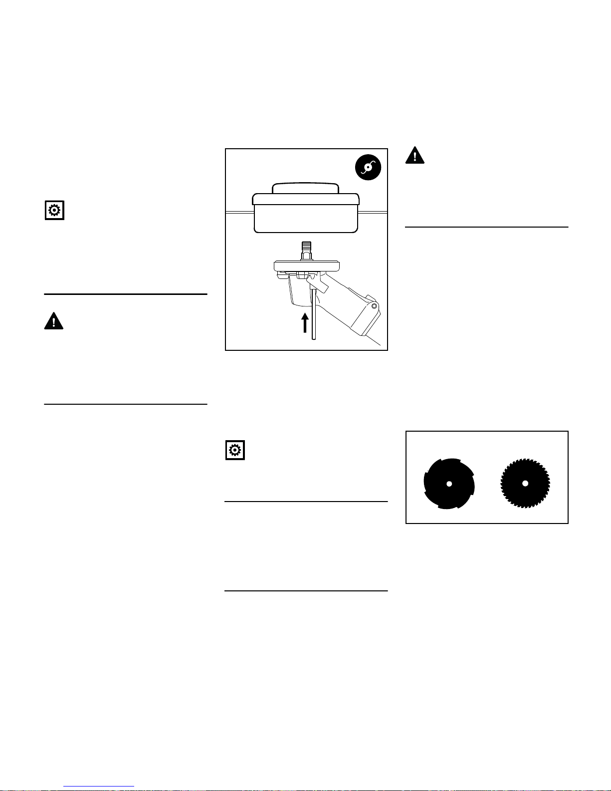
Fitting Mowing Head with Screw
Mounting
Keep the instruction leaflet for the
mowing head in a safe place.
All approved mowing heads are
mounted to the gearbox in the same
way.
N Check that the deflector on the
machine is approved for mowing
heads – if not, perform the next two
steps.
N Remove grass shield with thrust
plate – if fitted.
N Remove the non-approved
deflector.
N Mount deflector for mowing heads.
N Fit grass shield together with 60 mm
(2.4 in) diameter thrust plate.
N Screw the mowing head
counterclockwise on to the shaft (1)
as far as stop.
N Block the shaft.
N Tighten down the mowing head
firmly.
NOTICE
Remove the tool used to block the shaft.
Remove the mowing head.
N Block the shaft.
N Unscrew the mowing head
clockwise.
Removing and Installing Metal Cutting
Attachments
Before removing and installing metal
cutting attachments:
WARNING
Wear protective gloves to reduce the
risk of direct contact with the sharp
cutting edges.
Mounting Grass Cutting Blades
N Check that the deflector on the
machine is approved for grass
cutting blades – if not, perform the
next two steps.
N Remove grass shield with thrust
plate – if fitted.
N Remove the non-approved
deflector.
N Mount deflector for grass cutting
blades and brush knives.
N Fit grass shield together with 60 mm
(2.4 in) diameter thrust plate.
Check direction of rotation of cutting
attachment
The cutting edges of the grass cutting
blades 255-8 (1) and 250-40 Spezial (2)
must point clockwise.
1
002BA468 KN
1
2
681BA186 KN
FS 510 C, FS 560 C
English
25
N Place the cutting attachment (3) in
position.
WARNING
Collar (a) must locate in the cutting
attachment's mounting hole (b).
Securing the cutting attachment
N Fit the 60 mm (2.4 in) diameter
thrust washer (4) – convex side
must face up.
N Fit the 80 mm (3.2 in) diameter (A)
rider plate (5).
N Block the shaft.
N Screw on the nut (6)
counterclockwise and tighten it
down firmly.
WARNING
If the mounting nut has become too
loose, fit a new one.
NOTICE
Remove the tool used to block the shaft.
Removing the Cutting Attachment
N Block the shaft.
N Unscrew the mounting nut (6)
clockwise.
N Pull the cutting attachment with its
mounting hardware off the
gearhead.
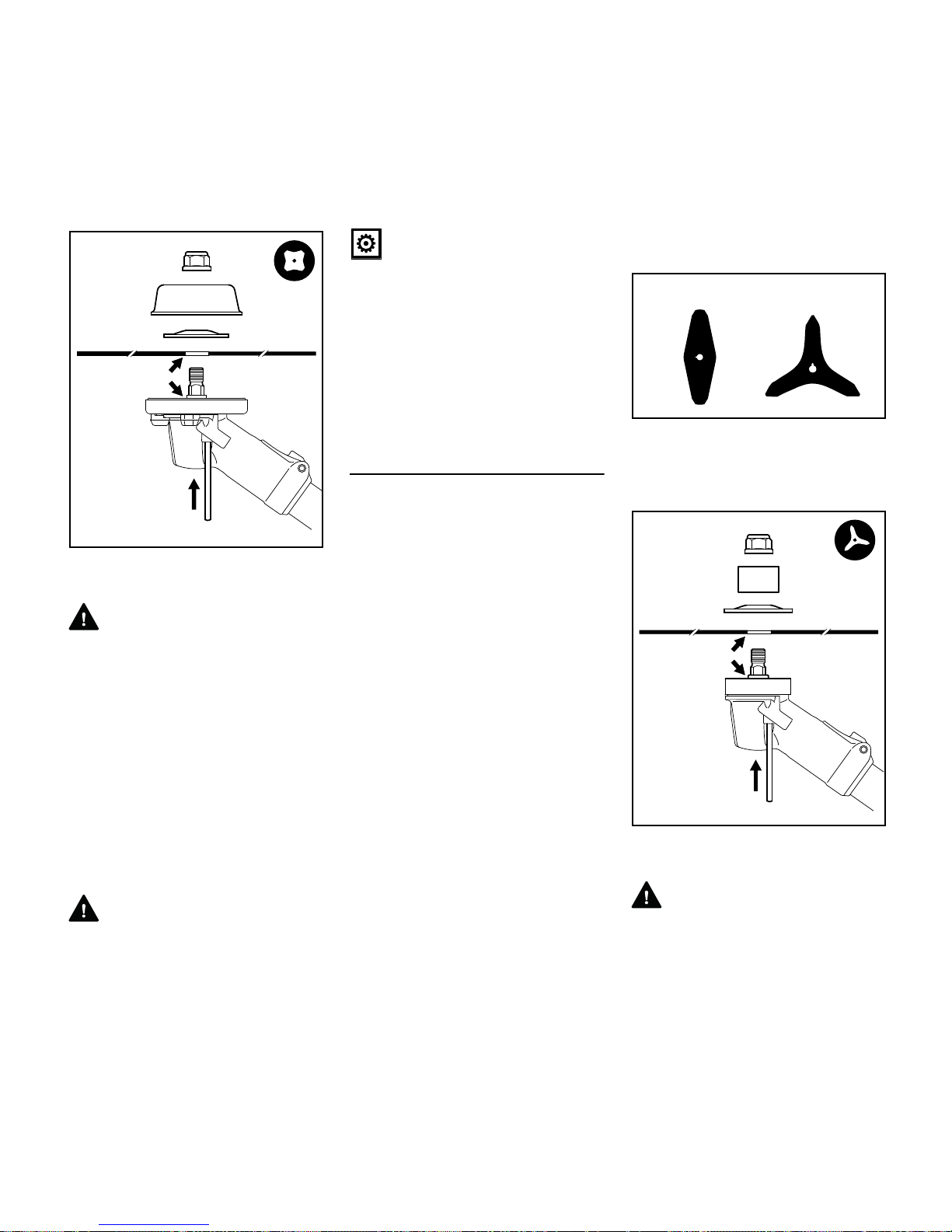
Mounting Brush Knives
N Check that the deflector on the
machine is approved for brush
knives – if not, perform the next two
steps.
N Remove grass shield with thrust
plate – if fitted.
N Remove the non-approved
deflector.
N Mount deflector for grass cutting
blades and brush knives.
N Fit the 65 mm (2.6 in) diameter
thrust plate.
Check direction of rotation of cutting
attachment
Brush knives 305-2 (1) and 350-3(2)
may point in either direction – these
cutting attachments must be turned over
regularly to help avoid one-sided wear.
N Place the cutting attachment (3) in
position.
WARNING
Collar (a) must locate in the cutting
attachment's mounting hole (b).
a
002BA469 KN
b
4
5
3
6
1
2
681BA187 KN
3
002BA494 KN
3
6
4
b
a
5
FS 510 C, FS 560 C
English
26
Securing the cutting attachment
N Fit the 70 mm (2.8 in) diameter
thrust washer (4) – convex side
must face up.
N Fit the guard ring (5) for brush
knives – opening must face up.
N Block the shaft.
N Screw on the nut (6)
counterclockwise and tighten it
down firmly.
WARNING
If the mounting nut has become too
loose, fit a new one.
NOTICE
Remove the tool used to block the shaft.
Removing the Cutting Attachment
N Block the shaft.
N Unscrew the mounting nut
clockwise.
N Pull the cutting attachment with its
mounting hardware off the gearbox.
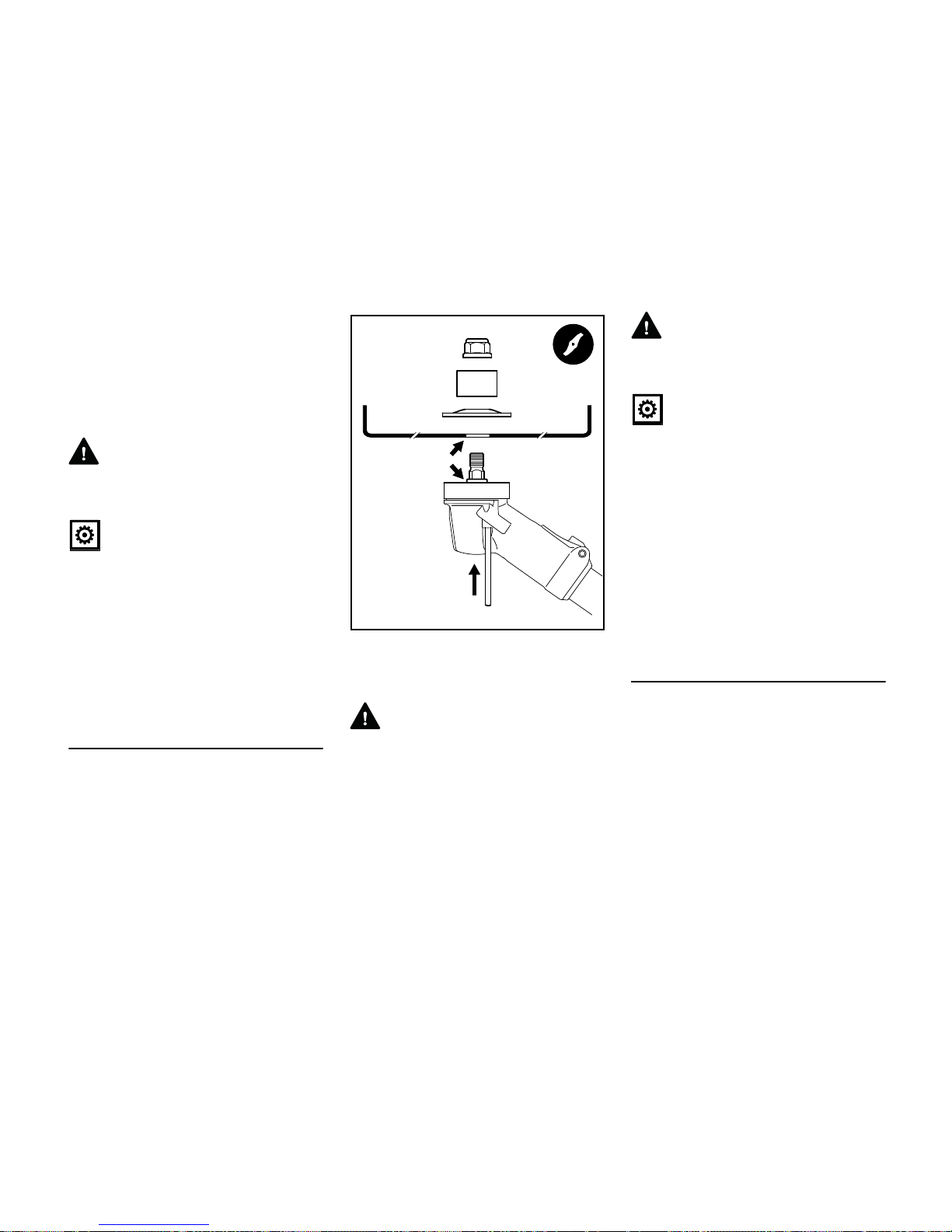
Mounting Shredder Blade 320-2
N Check that the deflector on the
machine is approved for shredder
blades – if not, perform the next two
steps.
N Remove grass shield with thrust
plate – if fitted.
N Remove the non-approved
deflector.
N Mount deflector for shredder blade.
N Fit the 65 mm (2.6 in) diameter
thrust plate.
N Seal the unused tapped holes with
plugs.
N Place the shredder blade (1) in
position – the cutting edges must
point upwards.
WARNING
Collar (a) must locate in the cutting
attachment's mounting hole (b).
Securing the cutting attachment
N Fit the 70 mm (2.8 in) diameter
thrust washer (2) – convex side
must face up.
N Fit the shredder blade guard ring (3)
– opening must face up.
N Block the shaft.
N Screw on the nut (4)
counterclockwise and tighten it
down firmly.
WARNING
If the mounting nut has become too
loose, fit a new one.
NOTICE
Remove the tool used to block the shaft.
Removing the Cutting Attachment
N Block the shaft.
N Unscrew the mounting nut
clockwise.
N Pull the cutting attachment with its
mounting hardware off the gearbox.
N If you intend to use a different
cutting attachment – remove the
shredder deflector.
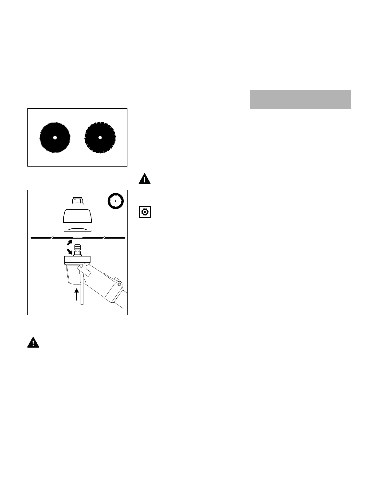
Mounting circular saw blades 225
N Check that the stop for circular saw
blades is already mounted to the
machine – if not, perform the next
two steps.
N Remove grass shield – if fitted.
N Remove deflector – if fitted.
N Mount limit stop for circular saw
blades.
N Fit the 65 mm (2.6 in) diameter
thrust plate.
N Seal the unused tapped holes with
plugs.
002BA470 KN
3
4
2
1
b
a
FS 510 C, FS 560 C
English
27
Check direction of rotation of cutting
attachment
Cutting edges of circular saw blades
must point clockwise.
N Place the cutting attachment (1) in
position.
WARNING
Collar (a) must locate in the cutting
attachment's mounting hole (b).
Securing the cutting attachment
N Fit the 60 mm (2.4 in) diameter
thrust washer (2) – convex side
must face up.
N Fit the 63 mm (2.5 in) diameter rider
plate (3).
N Block the shaft.
N Screw on the nut (4)
counterclockwise and tighten it
down firmly.
WARNING
If the mounting nut has become too
loose, fit a new one.
NOTICE
Remove the tool used to block the shaft.
Removing the Cutting Attachment
N Block the shaft.
N Unscrew the mounting nut
clockwise.
N Pull the cutting attachment with its
mounting hardware off the gearbox.
This engine is certified to operate on
unleaded gasoline and with the mix ratio
50:1.
Your engine requires a mixture of highquality premium gasoline and highquality two-stroke air-cooled engine oil.
Use premium branded unleaded
gasoline with a minimum octane rating
of 89 (R+M)/2.
Note: Models equipped with a catalytic
converter require unleaded gasoline. A
few tankfuls of leaded gasoline can
reduce the efficiency of the catalytic
converter by more than 50%.
Fuel with a lower octane rating may
result in preignition (causing "pinging")
which is accompanied by an increase in
engine temperature. This, in turn,
increases the risk of the piston seizure
and damage to the engine.
The chemical composition of the fuel is
also important. Some fuel additives not
only detrimentally affect elastomers
(carburetor diaphragms, oil seals, fuel
lines etc.), but magnesium castings as
well. This could cause running problems
or even damage the engine. For this
reason it is essential that you use only
high-quality fuels!
Fuels with different percentages of
ethanol are being offered. Ethanol can
affect the running behaviour of the
engine and increase the risk of lean
seizure.
681BA165 KN
2
1
4
002BA471 KN
3
b
a
Fuel
FS 510 C, FS 560 C
English
28
Gasoline with an ethanol content of
more than 10% can cause running
problems and major damage in engines
with a manually adjustable carburetor
and should not be used in such engines.
Engines equipped with M-Tronic can be
run on gasoline with an ethanol content
of up to 25% (E25).
Use only STIHL two-stroke engine oil or
equivalent high-quality two-stroke aircooled engine oils for mixing.
We recommend STIHL 50:1 two-stroke
engine oil since it is specially formulated
for use in STIHL engines.
To ensure the maximum performance of
your STIHL engine, use a high quality 2cycle engine oil. To help your engine run
cleaner and reduce harmful carbon
deposits, STIHL recommends using
STIHL HP Ultra 2-cycle engine oil or ask
your dealer for an equivalent fully
synthetic 2-cycle engine oil.
To meet the requirements of EPA and
CARB we recommend to use STIHL HP
Ultra oil.
Do not use BIA or TCW (two-stroke
water cooled) mix oils!
Use only STIHL 50:1 heavy-duty engine
oil or an equivalent quality two-stroke
engine oil for the fuel mix in models
equipped with a catalytic converter.
Take care when handling gasoline.
Avoid direct contact with the skin and
avoid inhaling fuel vapour.
The canister should be kept tightly
closed in order to avoid any moisture
getting into the mixture.
The fuel tank and the canister in which
fuel mix is stored should be cleaned
from time to time.
Fuel mix ratio
Only mix sufficient fuel for a few days
work, not to exceed 30 days of storage.
Store in approved safety fuel-canisters
only. When mixing, pour oil into the
canister first, and then add gasoline.
Dispose of empty mixing-oil canisters
only at authorized disposal locations.
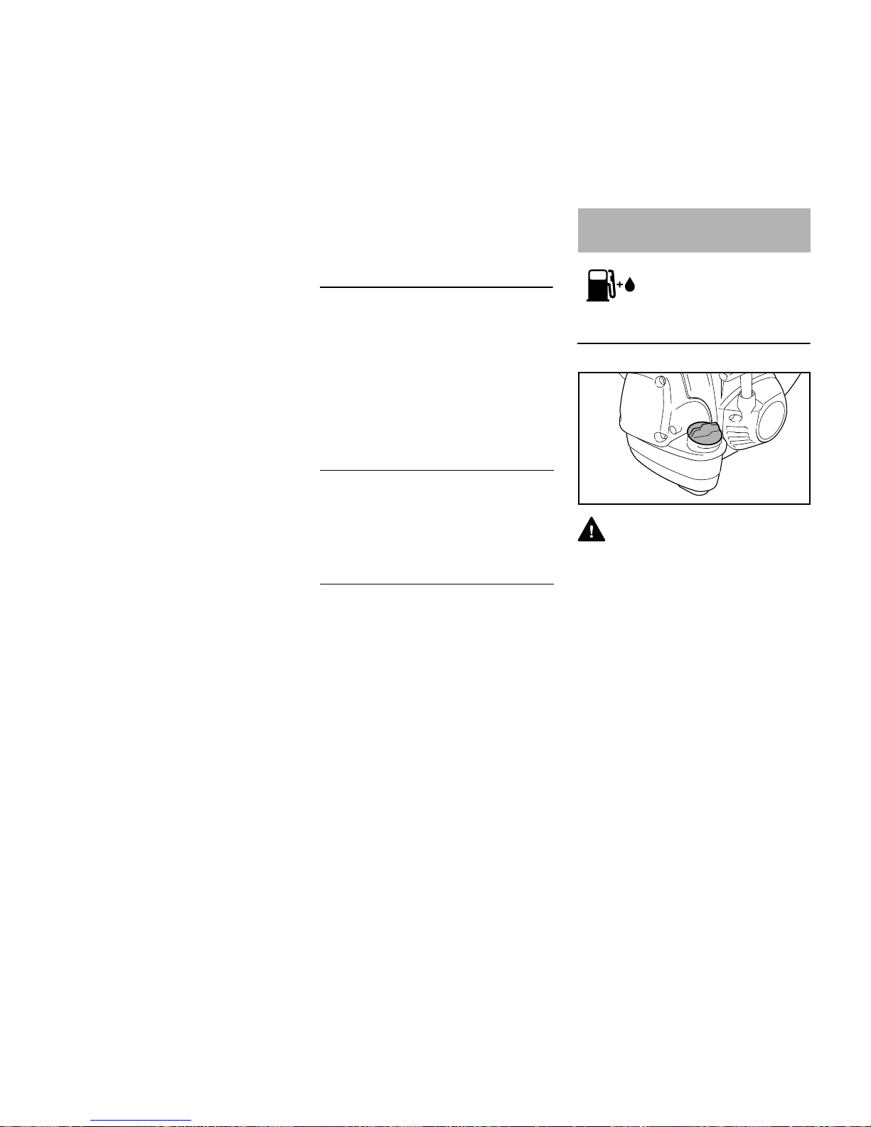
Preparations
WARNING
When fueling on a slope, always position
the machine with the filler cap facing
uphill.
N On level ground, position the
machine so that the filler cap is
facing up.
N Before fueling, clean the filler cap
and the area around it to ensure that
no dirt falls into the tank.
Examples
Gasoline Oil (STIHL 50:1 or equiva-
lent high-quality oils)
liters liters (ml)
10.02(20)
5 0.10 (100)
10 0.20 (200)
15 0.30 (300)
20 0.40 (400)
25 0.50 (500)
Fueling
4900BA016 KN
 Loading...