

Page 1
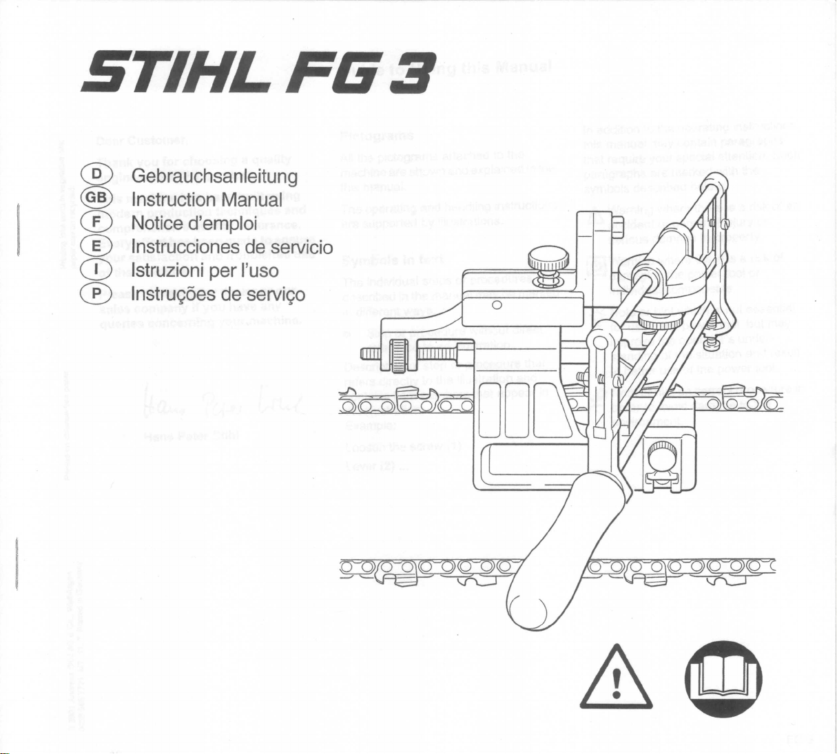
STIHL FG 3
@ Gebrauchsanleitung
@ Instruction Manual
CD Noticed'emploi
CD Instrucciones de seNicio
CD Istruzioniper I'uso
o Instrug6es de seNigo
Page 2
english
Guide to Using this Manual
Dear Customer,
Thank you for choosing a quality
engineered STIHL product.
This machine has been built using
modern production techniques and
comprehensive quality assurance.
Every effort has been made to ensure
your satisfaction and troublefree use
Printing inks contain vegetable oils;
paper can be recycled.
of the machine.
Please contact your dealer or our
sales company if you have any
queries concerning your machine.
Hans Peter Stihl
Printed on chlorine-free paper.© 2001 Andreas Stihl AG & Co., Waiblingen
Pictograms
All the pictograms attached to the
machine are shown and explained in the
this manual.
The operating and handling instructions
are supported by illustrations.
Symbols in text
The individual steps or procedures
described in the manual may be marked
in different ways:
: Step or procedure without direct
reference to an illustration.
Description of step or procedure that
refers directly to the illustration and
contains item numbers that appear in
the illustration.
Example:
Loosen the screw (1)
Lever (2) ...
In addition to the operating instructions,
this manual may contain paragraphs
that require your special attention. Such
paragraphs are marked with the
symbols described below:
Warning where there is a risk of an
accident or personal injury or
serious damage to property.
Warning where there is a risk of
damaging the power tool or
individual components.
Note or hint which is not essential
for using the power tool, but may
improve the operator’s understanding of the situation and result
in better use of the power tool.
Note or hint on correct procedure in
order to avoid damage to the
environment.
0458 566 7721. M2. K1. T. Printed in Germany
12
FG 3
Page 3
Safety Precautions Application
english
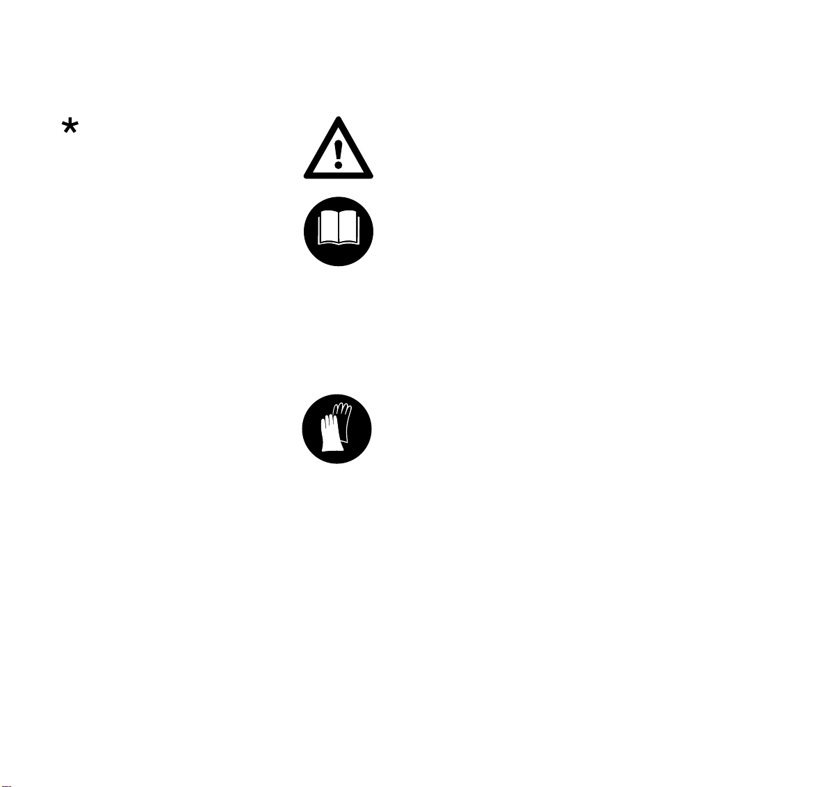
Equipment and features
This instruction manual refers to
several models with different
features. Components that are not
installed in all models and related
applications are marked thus
Such components are available as
special accessories from your
STIHL dealer.
*.
Engineering improvements
STIHL’s philosophy is to continually
improve all of its products. As a result,
engineering changes and improvements
are made from time to time. If the
operating characteristics or the
appearance of your machine differ from
those described in this manual, please
contact your STIHL dealer for
assistance.
To reduce the risk of
personal injury, special
safety precautions must
be observed while
operating the filing tool.
Read the operating
instructions carefully and
keep them in a safe place
for later reference.
Always shut off the saw engine before
working with the filing tool:
Move Master Control lever / slide control
or the separate stop switch to
STOP or $.
Electric saws: Disconnect plug from
power supply.
Wear gloves.
It is absolutely essential to comply with
the angles and dimensions specified in
these instructions. If the saw chain is
incorrectly sharpened – and in
particular if the depth gauges are set too
low – there is a risk of increased saw
kickback and personal injury.
Observing the safety precautions and
specifications in these instructions and
the owner’s manual of the saw model on
which the filing tool is mounted can help
reduce the risk of injury and damage to
the saw.
The STIHL filing tool can be used to
sharpen all STIHL Oilomatic saw chains
with the exception of square ground
chains (RSL, RSLF, RSLH) and carbidetipped chains (RD, RDS). Sharpening is
effected with the guide bar and chain
mounted on the saw.
For accurate results it is best to clamp
the guide bar in a bench vise or, at the
cutting site, in the STIHL bar vise
(special accessory).
File correctly
– Sharpen the chain frequently, take
away as little metal as possible –
two or three strokes of the file are
usually enough.
– Always file from the inside to the
outside of the cutter.
– The file only sharpens on the
forward stroke – lift the file off the
cutter on the backstroke.
– Avoid touching the tie straps and
drive links with the file.
13FG 3
Page 4

english
Setting Up
1
1
2
566BA003 KN
Use a slide caliper or similar to find the
shortest cutter. This is the master cutter
for filing all other cutters.
If the master cutter is in the left-hand row
of cutters, clamp the guide bar so that
the bar nose points to the right. If the
master cutter is in the right-hand row of
cutters, the bar nose must point to the
left.
: Place the filing tool on the guide bar.
: The clamping jaws (1) must face the
bar nose and be in line with top
edge of rivet heads.
: Tighten down the wing screw (2).
566BA002 KN
4
: Use the adjusting screw (3) to
center the filing tool above the
chain.
: Tighten the second clamping jaw
with the clamp screw (4) so that the
chain can still be pulled along the
bar with a screwdriver or suitable
rod engaged in a cutter.
3
566BA004 KN
14
FG 3
Page 5

Adjustments
Chain Type Filing Angle
Rapid Micro (RM) 30°
Rapid Super (RS) 30°
Picco Micro (PM/PMN) 30°
RCX, RMX, PMX
(ripping chain)
Chain Pitch File Diameter
inch (mm) mm (inch)
1
/
4
3
/8 PMN (9,32) 4,0 (5/32)
3
/8 P (9,32) 4,0 (5/32)
(6,35) 4,0 (5/32)
0.325 (8,25) 4,8 (3/16)
3
/
8
(9,32) 5,2 (13/64)
0.404 (10,26) 5,5 (
10 °
7
/32)
1
1 = Set the filing angle
2
3
: Fit the specified chain sharpening
file (2) in the two holders on the filing
tool and secure in positon with the
screws (3).
Use only special saw chain
sharpening files. Other files are
unsuitable for sharpening chains
566BA005 KN
because they have the wrong shape
and cut.
english
3
566BA006 KN
One notch on clamp is
equivalent to 5°.
15FG 3
Page 6

english
5
4
: Move top plate of master cutter (4)
so that it is approximately under the
center of the stop roller (5).
6
: Position the file (6) between the side
plate and depth gauge of the master
cutter by swinging and lifting the
filing frame.
566BA007 KN
: Rotate height adjusting screw (7)
(counterclockwise to lower file –
clockwise to raise file) until 1/10 of
file diameter projects above top
plate.
566BA008 KN
7
566BA009 KN
16
FG 3
Page 7

Sharpening
english
10 4
9
4
10
: Rotate the knurled nut (8) to move
stop (9) up against the back of the
cutter to be sharpened.
8
: Now rotate the knurled nut a little
more until the side plate presses
against the file and the stop bar (10)
is lifted about 0.1 to 0.2 mm off the
stop roller (4).
1
2
1
566BA010 KN
: Sharpen the master cutter with 2 to
3 firm strokes of the file. Always file
from the inside to the outside of the
side plate.
: The stop bar (1) should now locate
against the stop roller (2).
If this is not the case, readjust the
stop (3) slightly and pull the chain up
against it. Check the position of the
stop again.
2
3
566BA011 KN
17FG 3
Page 8

english
Use the setting for the master cutter to
sharpen all the other cutters in the row.
Second row of cutters
After sharpening all the cutters in the
first row, reset the filing tool to sharpen
the second row as described in chapter
“Adjustments”.
A
566BA012 KN
1
566BA014 KN
After sharpening the first cutter in the
second row:
: Check the cutter length (A).
3
: If it differs from te length of the
master cutter, change the position
of the stop (3), resharpen and check
again.
: If the length is correct, sharpen all
cutters in the second row using this
setting.
Depth gauges
Chain Pitch Filing Gauge
inch (mm) Part No.
1
/
4
3
/8 PMN (9,32) 0000 893 4000
3
/8 P (9,32) 1110 893 4000
(6,35) 1110 893 4000
0.325 (8,25) 1110 893 4000
3
/
8
0.404 (10,26) 1106 893 4000
566BA013 KN
(9,32) 1110 893 4000
: Place the appropriate filing
gauge (1) (special accessory) on
the chain. If the depth gauge
projects above the filing gauge, it
has to be lowered.
18
FG 3
Page 9

english
4
2
3
: Remove round file and fit the
triangular file (2) 0811 421 8971 in
its place.
: Set filing angle to 0°.
: Pull chain along bar until the depth
gauge is under the file.
: Adjust stop (3) until it butts against
the back of the cutter.
566BA015 KN
: Rotate height adjusting screw (4) so
that the depth gauge is filed back to
the required height (flush with
gauge). Then remove the filing
gauge and file down all depth
gauges to the same setting.
a
: Finish off by filing the slope by hand,
parallel to the stamped marking,
until dimension “a” is approx.
0.5 mm.
566BA016 KN
566BA017 KN
19FG 3
Page 10

english
Main Parts
1
4
5
2
3
8
6
1 Guide
2 Height adjusting screw
3 Lateral adjusting screw
4 Stop bar
5 Sharpening file
6 Adjusting screw
7 Wing screw
8 Stop
9 Clamp screw
10 Clamping jaws
20
79
1010
566BA001 KN
FG 3
 Loading...