

Page 1
Page 2
F
SERVICE MANUAL
028/038
FOREWORD
This Service Manual covers model
028 chain saws up to machine
number
5561640
as well as later
machines unless technical information
bulletins have been issued
in
the meantime with updated
repair procedures.
Models
038
have substantially the
same constructional features as
model 028 chain saws" This Service
Manual can therefore be used
for the 038 chain saws as
well.
In
the event of faults it is quite pos-,
sible
that a single malfunction may
have several causes. It is, there-
fore,
advisable to consult the
"troubleshooting charts" when
tracing
faults"
We
also recommend
that you make use of the
exploded
views
in
the illustrated parts lists
while
carrying out repair work.
This service
manual and all techni-
cal information bulletins are
in-
tended exclusively for the use
of
STIHL servicing staff and dealers
and must not be passed on to third
parties.
STI
H
L®
Andreas Stihl
Postfach 1760
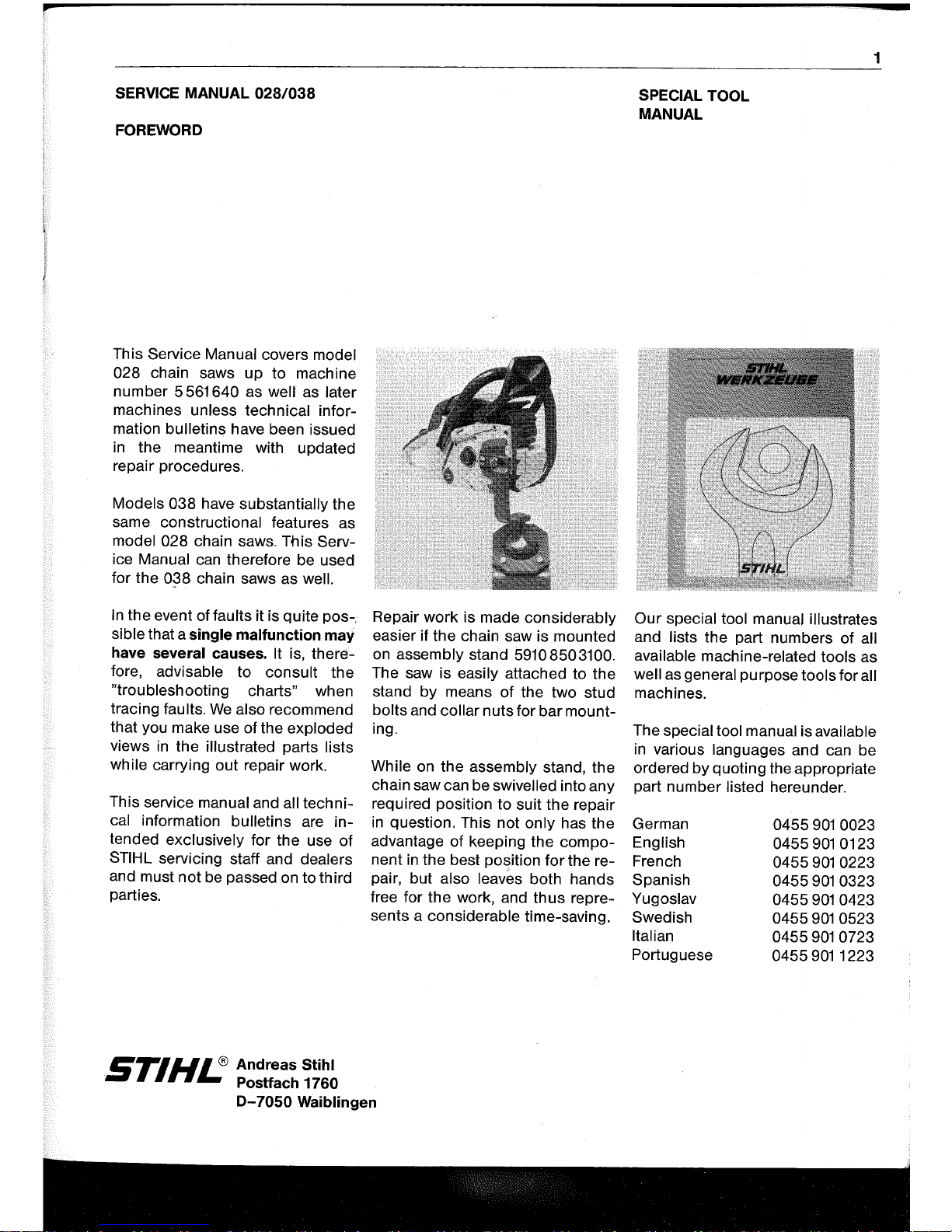
Repair
work
is made considerably
easier if the chain saw is mounted
on
assembly stand 59108503100.
The saw is
easily attached to the
stand by means
of
the two stud
bolts and collar
nuts
for bar mount-
ing"
While
on the assembly stand, the
chain saw can be
swivelled into any
required position to suit the repair
in
question" This not only has the
advantage of keeping the component
in
the best
position
for
the re-
pair, but
also leaves both hands
free for the work, and
thus
repre-
sents a considerable time-saving.
0-7050
Waiblingen
SPECIAL TOOL
MANUAL
1
Our
special tool manual illustrates
and lists the part numbers of all
available
machine-related tools as
well as general purpose tools for all
machines.
The
special tool manual is available
in various languages and can be
ordered
by
quoting the appropriate
part number
listed hereunder.
German
English
French
Spanish
Yugoslav
Swedish
Italian
Portuguese
0455
901
0023
04559010123
0455
901
0223
0455
901
0323
0455
901
0423
0455901 0523
0455
901
0723
0455
901
1223
Page 3
p
2
CONTENTS
1 .
Specifications
4 4
..
Ignition System 26 4
.. 5 ..
1
Checking on breaker-
4.1
Construction 26
controlled ignition
45
4
..
2
Operation 26 4.5.2
Adjustment on
breaker-
2
..
Clutch, Chain Drive 4 .
.2
..
1
General information
26
controlled ignition
45
and Chain Brake
7
4.2.2
Breaker-controlled
4
.. 5 ..
3
Checking on
electronic
2.1
Construction magneto ignition 27 ignition
47
and operation
7
4 .
.2
..
3 Bosch
transistor-controlled
4.6 Magneto edge
gap
48
2
..
1.1
Clutch and chain sprocket 7
magneto ignition 28
2
..
1.2
Chain brake
8
4.2.4
SEM
thyristor-controlled
2.2
Troubleshooting chart
8
magneto ignition
29
2.3
Disassembly
and repair
9
4
..
2.4..1
Charging the storage 5
..
Rewind Starter
49
2
..
3.1
Clutch
9
capacitor
29
5
..
1
Construction
2.3
.
.2
Chain brake
12
4.2
..
4.2Triggering the
thyristor
29 and operation
49
2.4
Assembly
13
4 . .2.4..3 Ignition 30 5.2 Troubleshooting chart
49
2.4.1 Chain brake
13 4
..
3
Troubleshooting chart
31
5.3 Disassembly
50
2.4 .
.2
Clutch
14
4.3.1
Breaker-controlled
5.4 Replacing the
starter
ignition system
31
rope
50
4
..
3 .
.2
Electronic ignition
5.5
Replacing the rewind
3
..
Engine 15 system 32 spring
51
3.1
Construction 15 4.4 Function and repair 5
..
6 Tensioning the rewind
3.2 Troubleshooting chart
15
of components 33 spring
51
3
..
3 Exposing the
cylinder
16
4.4..1
Spark
plug
33
5.7
Replacing starter rope
3.4 Disassembly of cylinder 4.4..2 Ignition lead
34 guide bush
52
and piston 16
4
..
4.3
Short-circuit
wire/ground
5
..
8 Routine maintenance
52
3.5
Assembly
of piston wire 35
and
cylinder
17
4.4.4
Short-circuit
contact
36
3
..
6 Disassembly of crankcase 4.4.5 Flywheel
37
-
removal
of
crankshaft 19 4
..
4.6 Armature
(Bosch)/ignition
6
..
AV Handle System
53
3
.
.7
Installing the
Crankshaft
module (SEM)
39
6
..
1
Construction
-
assembly
of crankcase21 4.4..6
..
1 Resistance
test
on
and operation
53
3.8 Leakage testing
primary winding
39 6
.
.2
Repair
53
the
crankcase
23 4.4..6.2Resistance
test
on
3
..
8.1
Pressure test 23
secondary
winding
39
3
. .8.2 Vacuum
test
25
4.4..6
..
3 Ignition coil
tester
40
3.8
..
3
Replacing the oil seals 25 4.4..6.4 Disassembly 7
..
Master Control
55
and
assembly
40
7.1
Construction
4.4.7
Condenser
41
and operation
55
4.4.8
Contact
set
42
7
.
.2
Disassembly
4.4..9
Trigger plate
44
and
assembly
55
4
..
5 Ignition timing 44
Page 4
8"
Electric Handle Heating
System
56
8,,1
Construction
and operation
56
8.2
Troubleshooting
56
8,,3
Disassembly
and assembly
58
8.3.1
Switch
58
8,,3,,2
Heating element
in pistol grip
58
8.3.3
Handlebar
58
8,,3..4
Generator
59
9"
Chain Lubrication
60
9.1
Construction and
operation of oil pump
60
9,,2
Troubleshooting chart
61
9,,3
Oil
tank/tank
vent
62
9..4
Repair
of
pickup body
and valve
62
9.5
Disassembly and repair
of
oil pump
63
1O"
Fuel System
64
1
0,,1
Construction and
operation
of
carburetor
64
10"1,, 1 Operation of fuel pump
64
1 0.1,.2 Operation of carburetor
64
10,,2
10,,3
10..4
10.5
10,,6
10,,6,,1
Troubleshooting chart
66
Leakage test
on carburetor
68
Disassembly
of
carburetor
68
Repair
of
carburetor
69
Carburetor adjustment
71
Notes for fine adjustment
of
carburetor
71
3
10.7
Fuel line and tank vent
71
10.8
Air filter and choke
72
Page 5
4
1. SPECIFICATIONS
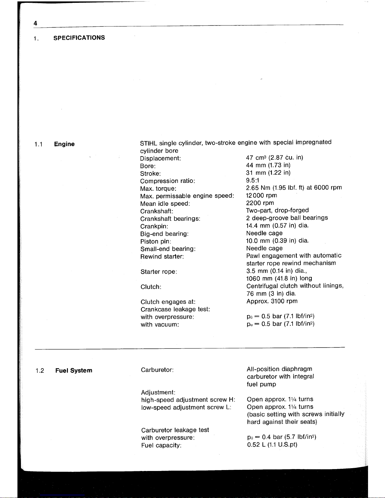
1.1
Engine
1.2
Fuel System
STIHL single cylinder, two-stroke engine with special impregnated
cylinder bore
Displacement:
Bore:.
Stroke:
Compression
ratio::
Max. torque:
Max.
permissable engine speed:
Mean
idle speed:
Crankshaft:
Crankshaft bearings:
Crankpin:
Big-end bearing:
Piston pin:
Small-end bearing:
Rewind starter:
Starter rope:
Clutch:
Clutch
engages at:
Crankcase
leakage test:
with overpressure::
with vacu u
m:
Carburetor:
Adjustment:
high-speed adjustment screw
H:
low-speed adjustment screw
L:
Carburetor leakage test
with overpressure:
Fuel capacity:
47 cm3 (2
..
87 tu. in)
44
mm
(1.73 in)
31
mm
(1.22 in)
9.5:1
2
..
65
Nm
(1..95
Ibf. ft) at
6000
rpm
12000
rpm
2200
rpm
Two-part, drop-forged
2 deep-groove ball bearings
14..4
mm
(0.57 in) dia.
Needle cage
10
..
0
mm
(0
..
39 in) dia.
Needle
cage
Pawl engagement with automatic
starter rope rewind mechanism
3.5
mm
(0
..
14
in) dia.,
1060
mm
(41.8 in) long
Centrifugal
clutch without linings,
76
mm
(3
in) dia.
Approx.
3100 rpm
po
= 0
..
5 bar
(7
..
1 Ibf/in2)
pu
= 0.5 bar
(7.1
Ibflin2)
All-position
diaphragm
carburetor with
integral
fuel
pump
Open approx.
11/4
turns
Open approx
..
1114
turns
(basic setting with screws
initially
hard against their seats)
po
= 0.4 bar
(5
..
7 Ibflin2)
0.52 L
(1..1
U.S.pt)
Page 6
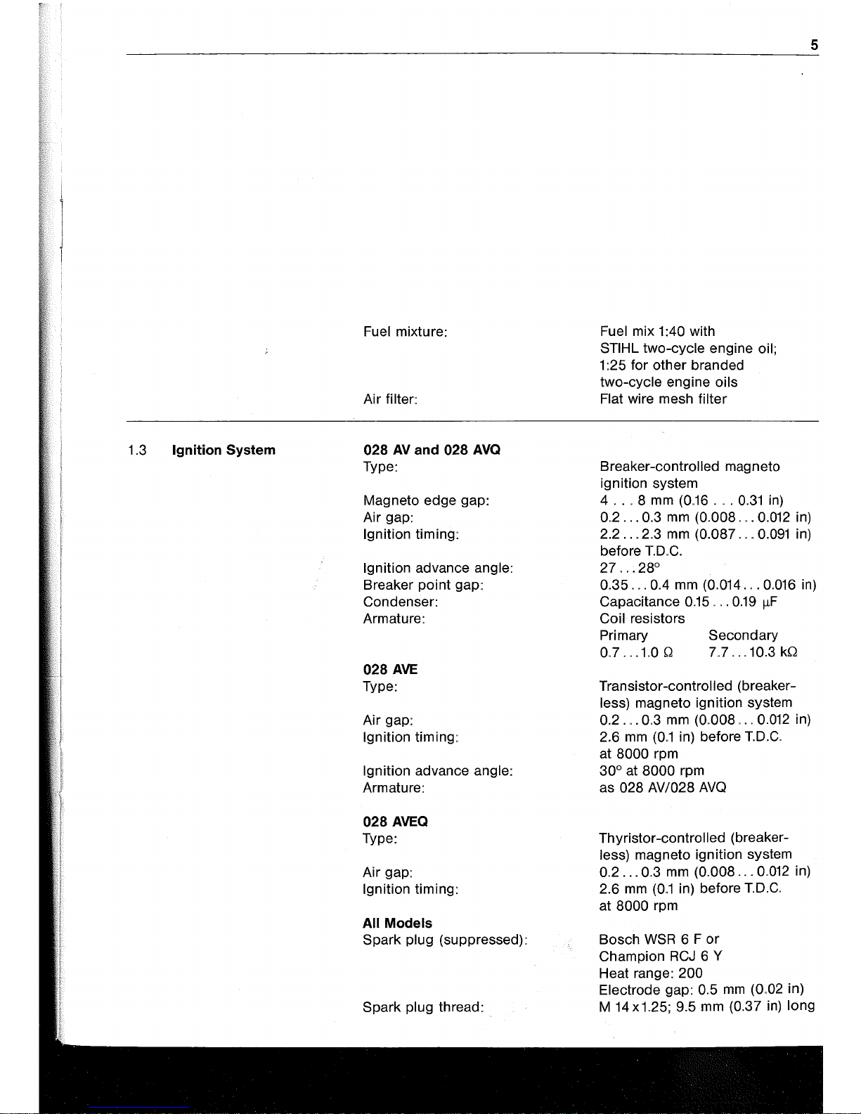
1.3
Ignition System
Fuel mixture:
Air
filter::
028
AV
and
028
AVQ
Type:
Magneto edge gap:
Air gap:
Ignition timing:
Ignition advance angle:
Breaker point
gap::
Condenser:
Armature:
028
AVE
Type:
Air gap:
Ignition timing::
Ignition advance angle:
Armature:
028
AVEQ
Type:
Air gap:
Ignition timing:
All Models
Spark plug (suppressed):
Spark
plug thread:
Fuel mix 1 :40 with
STIHL two-cycle engine oil;
1 :25 for other branded
two-cycle engine oils
Flat
wire mesh filter
Breaker-controlled magneto
ignition system
4
..
" 8
mm
(0,,16
. " .
0.31
in)
0,,2
...
0.3
mm
(0.008" " .
0.012
in)
2.2
..
,,2,,3
mm
(0.087" ,
,,0.091
in)
before
T..D"C.
27"".28°
5
0.35
...
0.4
mm
(0.014. , .0.016 in)
Capacitance
0.15" " .
0.19
IlF
Coil
resistors
Primary
0..7
...
1,,00
Secondary
7..7
...
10.3
kQ
Transistor-controlled (breaker-
less) magneto ignition system
0.2.
" .
0,,3
mm
(0,,008,. ,
0.012
in)
2.6
mm
(0,,1
in) before
T.D.C"
at 8000 rpm
30° at 8000 rpm
as
028 AV/028
AVQ
Thyristor-controlled (breaker-
less) magneto ignition system
0,,2
...
0.3
mm
(0.008
...
0,,012
in)
2.6
mm
(0,,1
in) before
T.D.C"
at 8000 rpm
Bosch
WSR
6 F
or
Champion
RCJ
6 Y
Heat range: 200
Electrode
gap::
0.5
mm
(0,,02
in)
M 14x1..25; 9.5
mm
(0.37
in)
long
Page 7

6
1.4
Tightening Torques
Crankshaft nut
(ignition side) M
8 x
1:
30
Nm (22 Ibf. ft)
Hub/spider
(output side):,
50
Nm
(37 Ibf.
ft)
M 5 socket head screws:
8 Nm (6
Ibf..
ft)
M
5 cheese-head screws:
5 Nm
(3,,7
Ibf. ft)
M
4 cheese-head screws:,
2.5
Nm
(1.8
Ibf..
ft)
M 5 nuts:
5 Nm (3.7
Ibf..
ft)
Spark plug:
25
Nm
(18,,4
Ibf..
ft)
Important: The M 5 x 12 screws on the front handguard and the
M 4 x 8 screws on the spider are fitted with LOCTITE.
1.5
Cutting Attachment
Guide
bars:,
STIHL Duromatic guide bars
with stellite-tipped bar
nose;
STIHL Rollomatic
guide bars
with sprocket nose. Both types
with corrosion resistant finish
and induction hardened track
Bar lengths:
Duromatic
40
and 45 cm
(16
and
18
in)
Rollomatic 32, 37, 40 and 45 cm
(13,14.6,16 and
18
in)
Chain:,
0.325" (8,,25
mm)
pitch
Chain sprocket::
7 -tooth for 0.325" chain
Chain
speed:,
16.4
m/s
(53.8 ft/sec) at
8500
rpm
Chain
lubrication:,
Speed-controlled
oil pump
with
lift plunger, operative
only when chairi is running
Oil delivery rate:
8 cm
3
/min
(0,,49
cu. in/m in)
at
6000
rpm
Oil tank capacity:,
0.3 L
(0,,63
U"S"pt)
1.6
Weights
Model:
AV/AVE
AVQ/AVEQ
Dry weight with
32
cm
bar and
chain:,
6,,5
kg (14.3
Ib)
6,,6
kg (14.5 Ib)
1,,7
Special Accessories
STIHL rescue kit
028
11189005000
Gasket set 028
11180071050
Page 8

2.
CLUTCH,
CHAIN DRIVE AND
CHAIN BRAKE
2
..
1 Construction and
Operation
2
.. 1 ..
1 Clutch and Chain Sprocket
The transmission of
power
from the
engine to the
saw
chain is effected
via a centrifugal clutch
..
O~
"Quick-
stop"
models, the centrifugal clutch
incorporates an isolating clutch
which
isactuated
by the chain brake.
On the Quickstop version the hub
screwed to the crankshaft is the
clutch element which absorbs the
torque and acceleration of the
crankshaft.. It is essential that the
hub is always tightened down to the
specified torque
..
The clutch
spider
is supported on the hub
by
a needle
sleeve and located axially with a
circlip
..
The driving plate is located
on
thethree
lugs of the clutch
spider
and can move axially while remaining in
constant
mesh with the
spider
..
The flat spring between the
spider and driving plate presses the
driving plate against the release
plate; this means
that
the internal
teeth of the driving plate are always
in mesh with the teeth of the hub
when the chain brake is released,
and thus provides positive
transmission of engine torque to the
clutch
spider
..
When the chain brake
is actuated, the release plate
dis-
engages the driving plate from the
hUb
..
The clutch
spider
and hub can
then rotate independently.
On the standard version the clutch
spider assumes the function of the
hub and must therefore always be
tightened to the specified torque
..
Chain
brake
engaged
The centrifugal clutch has three
clutch shoes
without
linings
..
The
clutch drum and chain sprocket are
separate components. The
spur
gear
which drives the oil pump is a
ring-gear,
positively
mounted to the
hub of the clutch drum
..
The chain
sprocket has two
integrally cast lugs
which engage in corresponding recesses on the drum hub
..
As the lugs
have odd sizes, the chain sprocket
can only be fitted in one position
..
When the engine is running at idle
speed the clutch shoes are also in
the idle position, because the
ten-
sion of the clutch spring is
greater
than the centrifugal force
..
As engine
speed increases, centrifugal force
presses the clutch shoes outwards
against the clutch drum and thus
transmit engine torque
positively
via
the chain
sprocket
to the saw
chain
..
The preload and strength of the
clutch spring are designed so
that
7
Chain
brake
released
the clutch shoes begin to make
con-
tact with the clutch drum at an en-
gine speed of approx
..
3100 rpm
(engagement speed)
..
The clutch
engages fully above this speed
..
The
correct idle setting on the
carbure-
tor
is therefore essential in
order
to
insure that the clutch engagement
speed is not reached when
the
en-
gine is idling
..
Page 9

8
2,,1,,2
Chain Brake
The chain brake is a
spring-loaded
band brake without linings" Its main
components are the brake band,
tension spring, handguard and release plate - which operates the
isolating clutch"
The chain brake is actuated by
means of the handguard which can
be used to release and engage the
brake"
2.2
Troubleshooting Chart
Fault
Saw chain turns at idle speed
The chain brake is
released (reset)
by pulling the handguard back
against the handlebar"
This
move-
ment is transmitted
via
a lever
system which preloads the tension
spring and
disengages
the brake
band. At the same time the release
plate moves back and
allows the
driving plate to engage in the teeth
of the hub"
The
brake lever, which is
connected to the tension spring,
brake band and release plate, is
locked in the idle position by the
relay lever.
Cause
Engine idle speed too high
Clutch spring stretched or fatigued,
spring hooks broken
Excessive chain
sprocket
wear
Incorrect chain tension
Chain stops in
mid-cut
even with Isolating clutch worn
engine at maximum speed Isolating clutch
disengages
Flat spring broken
during cutting
Isolating clutch does not re-engage Engine idle speed too high
after releasing chain brake
Flat spring broken
Saw chain does not stop
imme-
Tension spring broken
diately when chain brake is engaged
The chain brake is actuated by
mo-
ving the handguard
towards
the
bar
nose" This movement unlatches
the
brake lever and causes
the
brake
band to be clamped around
the
clutch drum by the force
of
the
preloaded brake spring" The release
plate simultaneously
disengages
the driving plate from the hub and
interrupts the flow of power between
the crankshaft and the centrifugal
clutch"
Clutch drum and
saw
chain
are brought to a
standstill within a
fraction of a second even if the
engine continues running at high
speed"
Remedy
Readjust at idle speed
adjustment
screw
Renew clutch spring
Tension saw chain properly
Renew hub and driving plate
Renew flat spring
Readjust at idle speed adjustment
screw
Renew flat spring
Renew tension spring
Page 10

2,,3
Disassembly and Repair
2,,3,,1
Clutch
Top:
Chain
brake
released
Bottom:
Pressing
out
the
retaining
washer
First remove chain sprocket cover
and cutting attachment..
The chain brake
must
be released
before removing the chain
sprocket
Use a screwdriver, about 5 mm
wide, to press the retaining
washer
out of the annular groove in the
crankshaft.
The
thrust
washer,
chain sprocket and needle sleeve
can now be pulled off the
cranks-
haft
Top:
Removing
the
side
plate
Center:
Releasing
the
cover
Bottom:
Ring-gear
removed
9
Top:
Removing
the
spur
gear
Bottom:
Clutch
drum
and
needle
sleeve
removed
Remove the inner side plate -
se-
cured with a single M 4 x 12
cheesehead screw" Unscrew the five
M 4 x
12
cheese-head
screws and
take off the cover" Now remove ring
gear
from clutch drum hub and the
spur
gear
(with worm) from the oil
pump shaft by turning it clockwise.
Pull clutch drum and needle sleeve
off
the
crankshaft
Page 11

10
Top:
Removing
the
circlip
Bottom:
Clutch,
flat
spring
and
needle
sleeve
removed
Disassembly differs on the
Quick-
stop and standard versions from this
stage onwards.
On the Quickstop version, first remove
the
circlip which locates the
clutch spider on the hub
..
The
clutch
with flat spring and needle sleeve
can now be pulled
off
the hub
..
If the
hub has to be removed, first remove
the driving
plate and block the
crankshaft..
To
do this, unscrew
Top:
Driving
plate
removed
Center:
Locking
screw
11071911200
Bottom:
Locking
screw
inserted
Top:
Special
socket
11188931300
Bottom:
Unscrewing
the
hub
spark
plug and fit locking
screw
11071911200 in the spark plug hole
and tighten down by hand
..
Use
spe-
cial socket 11188931300 to
unscrew
the hub. Remove
washer
from
behind hub
..
Page 12

Unscrewing
the
clutch
spider
The
crankshaft
must
also be blocked with locking screw11071911200
in
order
to remove the clutch
spider
on the standard version,
Use'
a
19
mm cranked ring wrench to un-
screw the
clutch
spider
and then re-
move the dished cover
plate"
Caution: The hub and clutch spider
have
left-hand threads - unscrew
them
clockwise.
Wash all parts of the clutch, including the needle cages, in clean
gasoline
and
blowout
with com-
pressed
air
if available" Also clean
crankshaft
stub"
Always replace damaged
or
worn
parts,
Top:
Removing
cover
plate
Bottom:
Clutch
spring
in
spring
recess
Use the following procedure to replace the clutch spring, clutch shoes
or spider:
First unscrew the
cover
plate from
the
spider
(Quickstop only) and then
remove the
clutch shoes"
Toassembletheclutch,
first position
the
clutch spring in the spring recess
of one
clutch shoe, so
thatthe
spring
11
Pressing
clutch
spring
into
position
hooks are
in
the
center
of the clutch
shoe" Now fit the three olutch shoes
on the arms of
the
spider
so
that
the
spring recesses face
away
from the
triangular plate on the spider" Grip
the
clutch spring with both
thumbs
and push it into
the
spring recesses
of the other two
clutch shoes.
Refit the cover
plate on the
Quick-
stop clutch" The three M 4 x 8
cheese-head
screws
must
be secu-
red with
LOCTITE"
Page 13

12
2.3,,2 Chain Brake
Detaching
the
tension
spring
The clutch drum must be removed
before the brake band can be disassembled"
To
do this, engage the
chain brake and detach the tension
spring" Remove retaining washer
from brake
lever's
pivot pin and
carefully withdraw the brake lever"
Collect
the washers and helical
spring on the brake
band's
pivot pin"
The other end of the brake band can
now be prised out
of
its seat in the
crankcase"
Take out the
clutch before removing
the
release plate" Remove the re-
taining washers, washers and
heli-
cal
springs from the guide pins and
take the
release plate out of the
crankcase"
Unscrew the handguard (the cheese-head screws
will be difficult to
remove because they are fitted with
LOCTITE) and then take out the
actuating
lever, relay lever and tor-
sion spring"
Top:
Removing retaining
washer
Center
and
Bottom:
Unscrewing
the
handguard
The spring guide pins in the crankcase must be
replaced if they are
damaged"
These screw pins
must
be bonded
in position to prevent them
loose-
ning in operation"
To
do this, use a
suitable solution (trichlorethlene,
diluted
nitro or similar) to
complete-
ly degrease the threads
in
the crank-
case and on the pins
themselves,
Then coat the threads of the screw
pins with a
little adhesive -
101,
part
number
0786
111
1101,
(LOCTITE
242) - and screw them into the
crankcase, Tighten to a torque of
4,,9
Nm (0.5 kpm).
It is essential to use a suitable
screwdriver with a tip which fits
snugly in the slot of the pin in order
to avoid damaging the pin materiaL
A 1 x 6.5 screwdriver in accordance
with
DIN 5265 is recommended for
this purpose"
Page 14

2..4 Assembly
24..1 Chain brake
Top:
Torsion
spring
and relay
lever
in
position
Bottom:
Actuating
lever
fitted
First fit the relay lever, actuating
lever and handguard. The ends
of
the torsion spring
must
engage in
the
hole in the crankcase and the
actuating
lever
..
The
M 5 x12
cheesehead screws must be secured with
LOCTITE.
Now fit release plate in crankcase
so
that
its slots locate
overthe
guide
pins
..
Fit washer, helical spring,
wa-
sher
and retaining
washer
on the
guide pins in
that
order
..
Locate bent
Seat
for
brake
band
end of brake band in its seat in the
crankcase and insert pivot pin of
brake
lever in the loop of the brake
band
..
Fit washer, helical spring and
washer on the pivot pin
of
the brake
lever
..
Push lever onto pivot pin and
locate pin in slot of release plate at
the same time. Now secure brake
lever with retaining
washer
and attach the tension spring using the
special assembly tool.
Top:
Brake
band and
brake
lever
in position
Center:
Special
assembly
tool
11178900900
Bottom:
Attaching
the tension
spring
13
Page 15

14
2..4.2 Clutch
Top:
Tightening
the
hub
with a
torque
wrench
First degrease the threads on the
crankshaft and hub (Quickstop)
or
clutch
spider
(standard) with a
suit-
able solution (trichlorethlene,
dilu-
ted nitro
or
similar)"
The initial
assembly
operations are
different on the
Quickstop
and stan-
dard versions
..
On the Quickstop version, fit the
flange
washer
on the crankshaft,
screw
hub
counter-clockwise
onto
the crankshaft and tighten to a
tor-
que
of
49.0
Nm (5
..
0 kpm) using the
special socket
11188931300
and a
torque wrench"
It is essential to observe the specified torque as the hub may otherwise
loosen during operation.
Engage the driving plate on the teeth
of the hub" The chain brake
must
be
in the
released condition during this
operation, Fit
flat spring on lugs
of
clutch spider; the raised spring tabs
Bottom:
Flat
spring
fitted on
spider
lugs
mustfaceawayfromtheclutch.
Now
push
clutch
together
with greased
needle sleeve onto the hub and turn
backwards and forwards until the
clutch
spider
lugs engage in the
driving plate.. Fit circlip to secure
clutch.
On
the standard version, fit cover
plate on the crankshaft so that the
raised outer
diameter
faces away
from the crankcase"
Screw
spider
of
clutch assembly
counter-clockwise
onto
the
crankshaft and tighten to a
torque
of
49.0 Nm (5.0 kpm) using
a torque wrench with a
19
mm socket.
It is essential to observe the specifiedtorqueasthespidermayotherwise
loosen
in
operation.
The
assembly
procedure is now the
same for both versions"
Lubricate
needle sleeve of clutch
drum with antifriction grease and fit
it on the crankshaft..
Push clutch drum onto crankshaft
and
needle sleeve and then fit spur
gear
onto oil pump shaft. Slip ring
gear
onto
hub of clutch drum.
Finish
off
by fitting cover and chain
sprocket; remove the
locking screw,
fit and tighten down the
spark
plug"
Page 16

3"
ENGINE
3
..
1 Construction
Series 028 chain saws are powered
by an
air-cooled, single cylinder
two-stroke
engine
..
The crankcase is a
two-part
pres-
sure die-casting made of a
special
magnesium alloy.. The
two-part
drop-forged crankshaft is supported
in two
deep-groove
ball bearings
..
Two oil seals, in the crankcase
atthe
ignition side and in the ball bearing
3.2
Troubleshooting Chart
Fault
Engine does not start easily,
stalls
at idle speed, but operates
normally at full throttle
Engine
does
not
deliver
full power
or
runs erratically
Engine overheating
at the other side,
hermetically seal
the crank chamber.
The connecting rod,
also
drop-forged, is supported on needle cages
both on the crankpin and the piston
pin.
Once the needle cage and the
connecting rod have been fitted, the
two
halves of the crankshaft are
pressed together to form a torsionally rigid assembly and then
First check
fuel supply, carburetor,
air
filter and ignition system before
looking for faults on the engine
..
Cause
Oil seals in crankcase
leaking
Elbow
connector leaking
Crankcase damaged (cracks)
Secondary
air
seepage into engine
through
poorly mounted
or
faulty elbow connector
Piston rings leaking
or
broken
Insufficient cylinder cooling
..
Air inlet opening in fan housing
blocked
or
cooling fins
on
cylinder plugged
15
machine finished
..
For this reason a
replacement crankshaft can only
be
supplied
complete with connec-
ting rod and needle sleeve.
Cylinder and piston are made of a
special aluminum alloy" The cylinder bore is impregnated in a special
process
..
Remedy
Replace oil seals
Seal
or
replace elbow connector
Replace crankshaft
Mount
elbow connector correctly
or
replace
Replace
piston rings
Thoroughly clean all cooling
air
openings
Page 17

16
3,,3
Exposing the Cylinder
Top:
Removing
the
shroud
Bottom:
Unscrewing
the
muffler
First remove carburetor box cover,
unscrew spark
plug and take off the
shroud and
two-part
muffler"
The cooling fins of the cylinder are
now
easily accessible and can be
cleaned thoroughly" Check for
da-
mage (cracks, broken cooling fins,
etc),
3.4
Disassembly of Cylinder
and Piston
Removing
the
cylinder
base
screws
Drain fuel and oil tanks, Remove the
carburetor (see
10.4) and unscrew
the four cylinder base screws" Carefully pull the cylinder off the piston
and press the
elbow connector for-
wards and
,out of the tank housing"
Before removing the piston it must
be decided
whether
or not the
crankshaft is to be removed,
Le. the
wooden
block used to lock the
crankshaft
- to facilitate removal of
the
flywheel and hub (Quickstop)
or
clutch spider (standard) - must be
fitted be1ween the crankcase and
the piston"
To
remove the piston, first take out
the two wire retainers and press the
piston pin out
of
the piston and nee-
dle cage by means of drift
11108934700.
If the piston pin is stuck as a result
of carbonization, tap it out lightly
with a hammer and the drift. It is
Top:
Removing
the
wire
retainers
Bottom:
Pushing
out
the
piston
pin
essential to counterhold the piston
to insure that no
jolts are transmitted
to the connecting
rod"
Remove the
piston"
Page 18

3..5 Reassembly of Piston
and Cylinder
Arrow
and"
A"
point
towards
exhaust
port
If the
cylinder
has to be replaced the
new
cylinder
must always be installed with a matching piston" Replacement cylinders are only supplied
complete with piston"
If only the piston is to be renewed,
every replacement piston (marked
"B")
can be used with any cylinder"
Before installing the piston, lubricate the needle cage with oil and
insert it in the connec!ing
rod"
Posi-
tion piston on connecting rod
sothat
the stamped markings (arrow and A)
point
towards
the cylinder exhaust
port (towards tip of guide bar)" Now
fit piston pin in piston and
connec-
ting rod (needle cage)"
To
do this,
push
assembly
drift
through piston
bore and connecting rod to align
both bores concentrically" Fit piston
pin on spigot of assembly drift and
slide into piston" Gently move piston
to and fro to ease insertion
of
piston
pin,
Fitting
the
piston
pin
The piston pin must move freely in
its bore. Never use force during
assembly.
Insert the two wire retainers and
make sure
that
they
are properly
seated,
Mounting of the cylinder is best
car-
ried out using the wooden
assembly
block and
the
ring
compressor
1113
893 4900 or clamping strap
00008932600"
The
elbow
connector
must
be fitted
if a new cylinder is used"
To
insure
a perfect seal, coat the inside
of
the
elbow
connector's
neck
with
sea-
ling paste 0783
810
1101"
Fit
elbow
connector
on the intake stub so that
it faces upwards (towards
cylinder
head) and the moulding seam is
vertical (parallel with
cylindercenter
line)" Then secure elbow
connector
17
Top:
Wooden
assembly
block,
ring
compressor
and
clamping
strap
Bottom:
Elbow
connector
in
position
with hose clamp, making
sure
that
the clamp is
correctly
seated and
does not
distortthe
elbow
connector
when tightened down.
Page 19

a
18
Top:
Piston on
wooden
assembly
block
Bottom:
Piston rings
correctly
positioned
Fit new
cylinder
gasket
on the
crankcase. Lubricate piston and piston
rings with
oil. Place wooden block
on the crankcase so
that
piston is
resting on
it..
Position each piston ring so that the
radii at
the
ring gaps locate against
their
respective fixing pins in the
piston grooves.
Fitting
the
cylinder
Insert the
four
M 5 x
16
socket head
screws in the
cylinder mounting
holes
..
Using the ring
compressor
or
clamping strap,
compress
the piston
rings
while making sure
they
are
correctly positioned.. Fit
cylinder
over
the piston with the exhaust port
facing in the direction of the
guide
bar
tip
..
During this process make
sure
that
the cylinder is properly
aligned, Le.
the
outer
edges of the
cooling fins must be exactly parallel
with the outer edge of the crankcase
atthe
sprocket side
..
Ifthis
alignment
is not carried out,
the
piston rings
may
break
..
The ring
compressor
is
pushed downwards as the piston
rings
move into the cylinder
..
Re-
move wooden
assembly
block and
ring compressor..
Push flange of
elbow
connector
through the bore
in the
tank
housing (do not use a
sharp
tool
forthis
purpose) and align
the cylinder
gasket
and cylinder
..
Tighten down the
four
cylinder
base
screws to a
torque
of 7 .. 8 Nm
(0 .
.8
kpm) in a diagonal pattern..
Tightening
cylinder
base
screws
with
torque
wrench
Insert sleeve in
elbow
connector
and then refit
carburetor
(see 1004),
muffler, shroud, spark plug and
car-
buretor box cover
..
Page 20

BUYNOW
ThenInstantDownload
theCompleteManual
Thankyouverymuch!
 Loading...