

Page 1

Page 2

Congratulationsl
You
are
the
owner
of a
precision-manufactured
STlHL
chain
saw
designed
to
give
you
long
and
dependable
service.
To
receive
maximum
performance
and
satisfaction
from
your
STlHL
chain
saw,
it
is
important
that
you
read
and
understand
the
maintenance
and
safety
precautions
before
using
your
saw.
Contact
your
STlHL
Dealer
or
the
SllHL
Distributor
for
your
area
if
you
do
not
understand
any
of
the
instructions
or
warnings
in
this
Manual.
This
Manual
contains
warnings
regarding
your
saw,
operating
and
safety
instructions for all
STlHL
090
series
power
saws.
Warning I
Because a chain
saw
is a high-speed
wood-cutting
tool,
some
special
safety
precautions
must
be
observed
as
with
any
other
power
saw
to
reduce
the
risk of
personal
acci-
dents.
Careless
or
improper
use
may
cause
serious
or
even
fatal
injury.
It
is
important
that
you
fully
understand
'the
contents
of
this
Manual
and
that
you
allow
only
persons
who
understand
this
Manual
to
operate
your
chain
saw.
Pay
special
attention
to
the
safety
precautions
and
cutting
techniques
outlined
on
pages 4 to
19.
STIHL!s
philosophy
Is
to
continually
improve
all
of its pro-
ducts.
As
a
result,
engineering
changes
and
improvements
are
made
from
time-to-time.
Written
notices
relating
to
such
changes
are
sent
to
STIHL
Dealers.
If the
operating
characteristics
of
the
appearance
of your
saw
differs
from
those
described
in
this
Manual,
please
contact
your
local
STlHL
Dealer
for
updated
information
and
assistance.
0458
166
0121.
MO,7S.AO.1:
Printed In
West
Germany
x
8nHL
090,
090
AY,
090
G
Instruction Manual/Owner's Manuals, .
Sharpening and Maintenance
of
Saw Chains
Contents
Parts of
the
Chain
Saw
Satety
Precautions
-
The
Operator
-The
Saw
-
The
Use
of
the
Saw
-
Maintaining
and
Storing
the
Saw
Mounting
Guide
Bar
and
Chain
Fuel
Chain
Oil
Helpers
Handle
Starting
011
Quantity
Control
Cutting
Attachment
Air
Filter
Carburetor
.
Replacing
the
Chain
Sprocket
Gear
Lubricant
090 G
Rewind
Starter
Maintenance
Chart
Specifications
Sharpening
and
Maintenance
of
Saw
Chain
STIHL~
C
1990
Andreas
Stlhl,
Walblingen
Andreas Stihl
D-7050 W8lblingen
2
4
4
6
6
19
20
22
22
23
24
27
28
30
31
32
33
34
36
37
39
1
Page 3
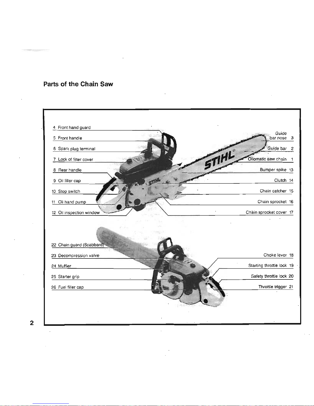
Parts
of
the
Chain Saw
4 Front hand
Guide
5
Front handle
bar nose
3
6
tenninal
Guide
bar
2
of filter cover
Bumper spike
13
9 Clutch
l'
O'lain catcher 15
Oil
hand
Chain
16
12
Oil
22 Chain
23
Choke lever
18
throttle lock
19
25 Slarter throttle lock
20
2
Page 4

Defil1llfOns
1.
Oilo~
Saw
Chain. A
J09P
~
of
cutters.
tie straps
~drive
links. . ','
~,.-
2. Guide Bar.
Su_~:ijuJdes
the
saw
chain.
.
";.,:
)"'~:
~:/r~
3. Gu
..
~rNose.:~~,paitoftheguidebar.
4.
~
~auarii.-~.::\~
afnst
ro..
~
.,."
PI,
ag P
jecting
~fInd
helps prevent the left
hand
from
touchi
ttcEt
Ch8tn
if
It
slips off
the
handle bar •
•
0<
,.:,._.,..J!~t
",,-of
.. ' ',',
',,,,,
, ,
5.
Front Handle.
Handle
bar
for
the left
hand
at front
of
saw.
6.
Sp;idc
Plug
TemdnaL Connects the spark
plug
with
1he
i9nHiOn
Wire.
7.
Lock'or-Filter
Cover. For
remoVing
filter cover, per-
rnitS1Uter
to.be
cIearied.:
8.
,
Rear'Handle-The
Support
handJe
for the right hand,
. Iocited at
or
tOward
the
rear
of
the
saw.
9.
Oil
Fftier
~For
closing
the
011
tank.
10.
Stop
Switch. Switches
the
engine's
ignition
system
off
and
stops the
running
of
the
engine.
11.
Oil Hand Pump.
For
additional
manual
c::;haln
lubri-
cation..
12.
011
Inspection
WIiu:Iow.
For
contrO'mng
the
chain
011
level.
13. BUmper
~
Toothed
stop
for
holding
saw
steady
againSt
wood.
14.
ClUtch.
C()upJes
engine
to
chain sprocket
when
engine
is accelerated beyond Idle
speed.
15.
Chain
Catcher. Catches a broken chain
and
guides
It inside
the
chain
sprocket COVet
""~~~~\'
16.
cta8fr.
8prf;K=ket.
The toothed wheel that drives the
sawctUll~
.
17.
Chain.Sprock8t
Cover. Covers the clutch and the
sproClCet.
18.
Choke
Lever.
Eases engine starting
by
enriching
~ixlure.
19.
Startfng Throttle Lock.
Keeps
the throttle partualJy
~n
~ring
starting.
20.
~
Throttle
Look.
Must
be
depressed before
~
the
throttle
trigger.
21.
Throttle
TrIgger. Controls
the
speed of the
engine.
22. ChaIn Guard (Scabbard). Protects
the
operator
from
touchil1$1
the
chain.
23. Decompfession Valve. Makes starting easier.
24.
Muffler.
Attenuates
exhaust noises
and
diverts ex-
haust
gases
i~,
req~lreQ
~on.
25.
Starter
~'The,
grip
Of
the,
pull
,starter.
which is
the
device
to
start the engine.
26.
Fuel
FlUer
Cap.
For
closing
the
fuel tank.
3
Page 5
Safety Precautions
The
use
of any chain saw may
be
hazardous.
The
saw
chain
has
large,
sharp cutters. If the cutters contact your
flesh,
they
will
cut
you,
ewn
H the
chain,
is not
m9VIns.'
At
full
throttle,
the chain
speed
can
reach
45
mph
'(20
ri1Is).
It is
important that
you
read,
fully
understand
and
observe the
following .
safetY
precautions
and
.
warningS.
;Read
the
owner's
manual and the safety'
inStructions
periOdically.
Pay
special attention to the section
on
reactive
forces,
pages
10
to 13.
Warning!
Reactive
forces,
including
kickback,
can
be
dangerous.
Careless or improper use of any chain
saw
may
cause
serious or fatallnjuiy. . ' , .
All
safety precautions that are generally
observed
when
working with Bnaxeor a'hand
saW
aisoapply
~
the'opefa-
lion
of
chain
saws.
HOWever;
beCause
'8
Chain
saw
is a
hlghspeed,
fast cutting power
tool,~a1
safety
pre-
cautions
must be
obSerVed
to
reduce
,tti~~
risk of
personal
accidents. . -.
Have
your
,STIHL
dealer
show
you
how
to operate
your
chain
saw.
ObserVe
all
appllCabra'~
safetY
'regulations,
standards
and
ordinances.
,Warning!
4 Minors should never
be
allowed
to
use a chain
saw.
2
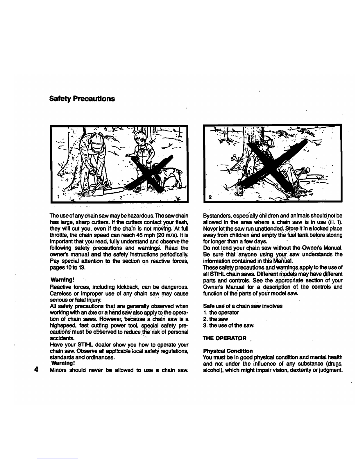
Bystanders,
espedally children
and
anim~s
should
.not
be
allowed in the area where a chain saw is
in
use
(ill.
1).
Never letlt\e saw
run
unattended.
$.Ore
it in a
locked
place
away
from
'Children
and
empty
the fuel
tank
before
stonng
for longer than a few
days.
. .
Do
not
lend
Y'0ur
chain saw without the Owner's
Manual.
Be
sure
that
'anyone'
'using
,yO~'saw
understands
the
information contained in this Manual.
These
safety precautions
and
waqlings apply
to
the
use
of
all
STlHL
~n
saws.
Different
~odc$
may
have
~erent
parts
and
controls. See the 'appropriate section of your
Owner's
Manual for a description of the controls
and
function of
the'
p8rts
of your model
saw.
Safe
use
of a chain
SaW
involves
t the operator
2. the saw
3. the
uSe
of the
saw.
THE
OPERATOR
Physical
Condition
You
must
be
in good physical condition and
mental
health
and
not under the influence of
any
substance
(drugs,
alcohol),
which might impair vision, dexterity
or
judgment.
Page 6
Do
not
operate a chain saw when
you
are fatigued
(UI.
2).
Be
alert
.:.. H you
'get tired while
operating
yOlir ctiain
saw,
take.
a
~r~ak.
tiredness
may
result
,in
.1oSs~f
co~.
Working
vVith
aity,chaiO
saw.
can
De
'Strenu()us.
If
you
have
any . conditiOn
tfiat
inight
..
be
aggravated by 'strenuous
work.
check
with
your doctor
befOre
operating a chain
saw.
~!
PtoIonged.~
ofcl1ain saws (or other
m~ines)
exposing
the
operator to vibrations may produce Whitefinger dis-
ease
(Raynaud's phenomenon). This phenomenon redu-
ces
the hand's ability to
feel.
and regulate temperature,
produces
numbness andburriing sensations
and
may
•
cause
nerve
and
circulation damage
and
tissue necrosis.
MinySTIHL
models
are'
available with
an
anti-vibration
system
designed to reduce engine 'vibration.
An
anti-
vibration system is recommended for those using chain
saws
on
a regular or sustained basis.
Heated
handles help to reduce the risk of Whit8finger
disease and
are
recommended for cold weather
use.
Most
STlHL
Powerheads
are available with heated handles.
Anti-vibration
sYstems
and
he~ecI
handles do not gua-
rantee
that
you
will not,sustain Whitefinger
d"lS8ase~
There-
fore continual
and
regular users'should 'monitor clOsely
. their
use
of chain saws
and
their physical condition.
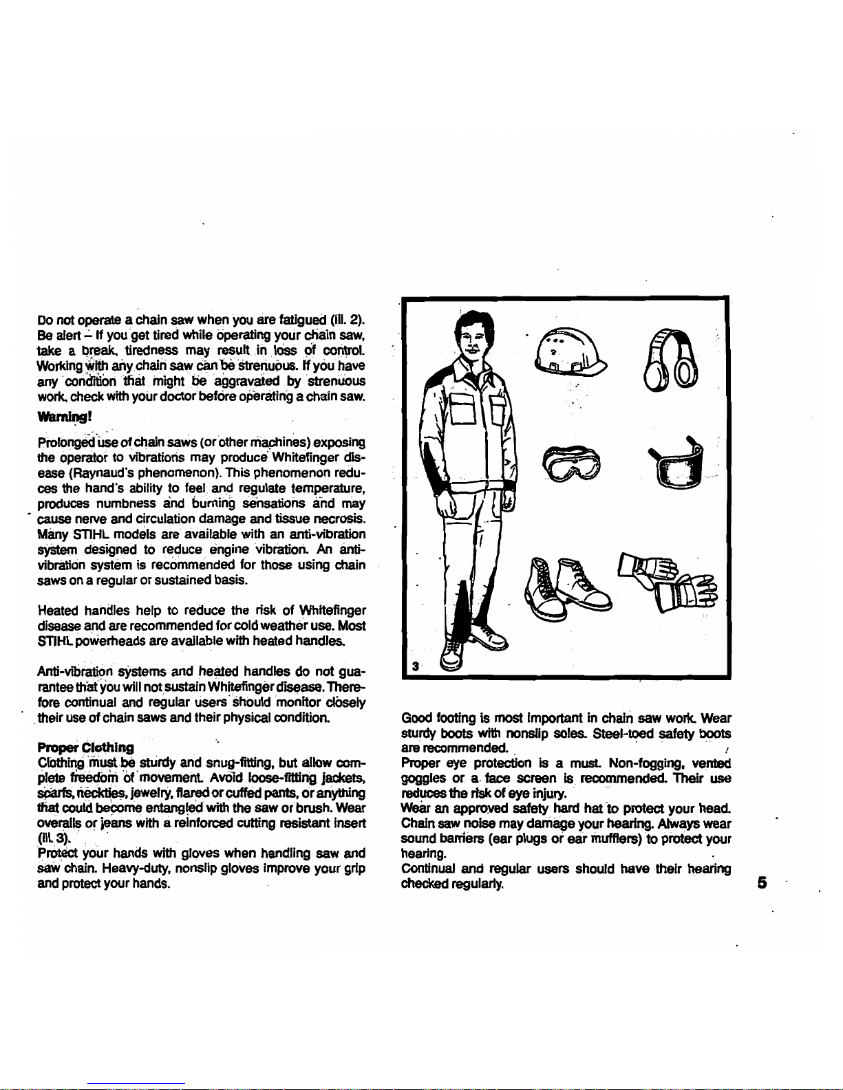
Proper Clothing .
'.
CIOthil1Q
'musfbe stUrdy
and
snug-fitting. but allow
c0m-
plete
fieedom
of'
movement.
AvOId
Ioose-fitting jackets,
~
~.jeweirY.
~
or~
pants,
or
anYthing
that could
become
entangled
with the
saw
or brush. Wear
ove~~
o~
jeans
with'
a reinforced
cutting
resistant insert
(Ill
3). , . .
p.
your hands with gloves when handling saw
and
saW
chain.
Heavy-duty, nonslip gloves improve your grip
and
protect your
hands.
Good
footing is most Important
in
chain
saw work.
Wear
sturdy boots
with
nonslip soles. Steel-toed safety boots
are
recommended.
. ,"
>.
Proper
eye
protection
Is
a must. Non-fogging, vented
goggles or a.face screen
is recommended. Their use
reduces the risk of eye
injury.
" "
Wear
an
approved safety
hard
hat
to
protect your
head.
Chain
saw
noise may darriage your hearing. Always wear
sound barriers (ear plugs
or
ear muffters)
to
protect your
hearing.
Continual
and regular users should have ·their hearing
checked
regularty.
5
Page 7
4
THE
SAW
Parts
of
the
chain
saw;
Illustrations
and
definitions
of the
parts
see
pages
2 and
31
~I
NevermodHy a
chain
saw
in
any
way.
Only
attachments
supplied
by
STlHL
or expressly
appro~,!)y
STlHL
,for
use
with
the
specific
STlHL
saw
modelS
,are.
authorized.
Although
certain
unauthorized
attachmentsaie
useable
with
the
STlHL
powerhead.
their
use
may,
in
fact,
.be
extremely dangerous. '
THE
USE
OF
THE SAW
TranSporting the
chain
saw
W8ming!
AJW8yS
Stop
the
enQtne
before'pUtting a chain
saw
down or
carryi~
~. ~ ~
.chain'
sti~;with
~'
engine
running
is extteinely
dangerous.
'A'CCidentaJ
acceleration
of the
engine
eancsuse
the
chain to
rotate.
Avoid
touchmg
the
hotmUffter.' .
.~
.
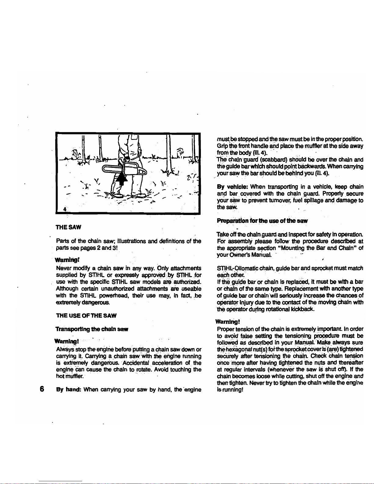
6
By
hand:
When
carrying
your
saw
by
hand,
the
'engine
must
be
stopped
and
the
saw
must
be
in
the
proper
position.
Grip
~e
front
handle
and
place
the muffler at the
'side
away
from
the
body
(i1l.4).
" .
1tl8'
c;hafn
-guard
(scabbard)
~Uld
tie
over
the
chain
and
the
gu~
barWhfCh
~rd
P9fljt
b8ckwards.
When
carrying
your
~
~
barsttould be behind
you
(i1l.4).
By
vehicle: When transporting in a
vehicle,
keep
chain
EiI19
bar,
~v~red
with the
ch~n.guard.,
Properly
,secure
your
saw
to
prevent
turnover,
fuel
SpHlage
and
damage
to
the
saW.
" .
Prepaf8tion
forihe
use
of
the
saw
T~
off the
chain
guard
and
inspect for safety in
operation.
For
assemblY
please
foUow
~
procedure described at
the
appropriate
section "Mounting
the
Bar
and
Chafn" of
your owner's
Manual.
'
STlHb-Oilornatic
chain,
guide
bar
and
sprocket
must
match
eaCh
other:'
' " .
."
If
the,
g~i48
~r
'or chain Is
~1aC8dt
it
must
be
with
a bar
or
Ch8In
of the
same
type.
ReplaCement
with
another
type
of
guide bar or
chain
'wiD
seriously
increase
the
00,ances
,of
ope~
iF.ljury
~ue
t()
the
Contact
of
the
'moving
chain
with
.~
operator
during
n;rtational
kicIcb8ck.
W8rnirig!
Proper
tension
of
the
chain is extremely important. In order
to
av~
~
.setting the
tensiol1ing
~we
must
'be
fot~
as,
d~
in
Y9ur
~"'M~,~ys
~re
~h,e*agoraarn~s>'fotthesp~coveriS(~)~
seCuteJy
after
tensioning,
~e
.chaffL
CheCk
Chain
t~n
once'~
after
t:taving.
tigtlte.ned
the
n~
and thereafter
at
regular
intervals
(Whenever
the
saw
is
shut
off).
If
the
chain
becomes loose while cutting,
shut
off the
engine
and
then
tighten.
Never try to tighten the chain
while
the engine
is
runningl
Page 8
5
Fueling
-
Your
STlHL
chain
saw
uses
an
oll-gasoline mixture for
fuel
(see chapter"
Fuel
n of your
Owner's
Manual).
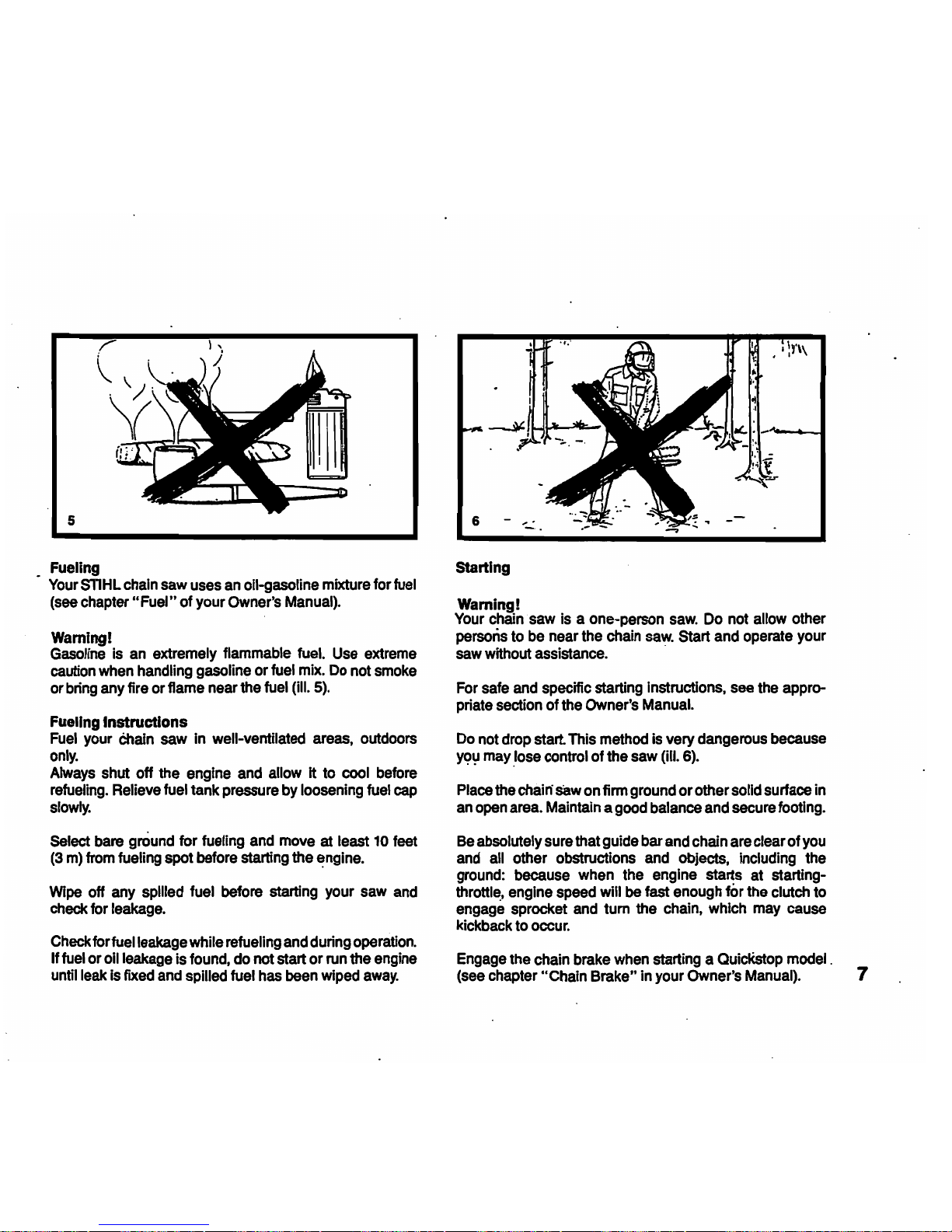
Warning!
Gasoline
is
an
extremely
flammable
fuel.
Use
extreme
caution
when
handling
gasoline or
fuel
mix.
Do
not
smoke
or
bring
any
fire
or
flame near the
fuel
(ill. 5).
Fueling
Instructions
Fuel
your
Chain
saw
in well-ventilated
areas,
outdoors
only.
Always
shut off the
engine
and
allow
It to
cool
before
refueling.
Relieve
fuel
tank
pressure
by
loosening
fuel
cap
slowly.
Select
bare
ground
for fueling
and
move
at
least
10
feet
(3
m)
from
fueling spot before starting the
~ngine.
Wipe
off
any
spilled
fuel
before
starting your
saw
and
check
for
leakage.
Check
for
fuel
leakage
while
refueling
and
during
operation.
If
fuel
or
011
leakage
is
found,
do not start or
run
the
engine
until
leak
is
fixed
and
spilled fuel
has
been
wiped
away.
6
Starting
Wamlng!
Your
chain
saw
is
a one-person
saw.
Do
not
allow
other
persons
to
be
near
the
chain
saw.
Start
and
operate
your
saw
without
assistance.
.
For
safe
and
specific starting Instructions.
see
the
appro-
priate
section
of the
Owner's
Manual.
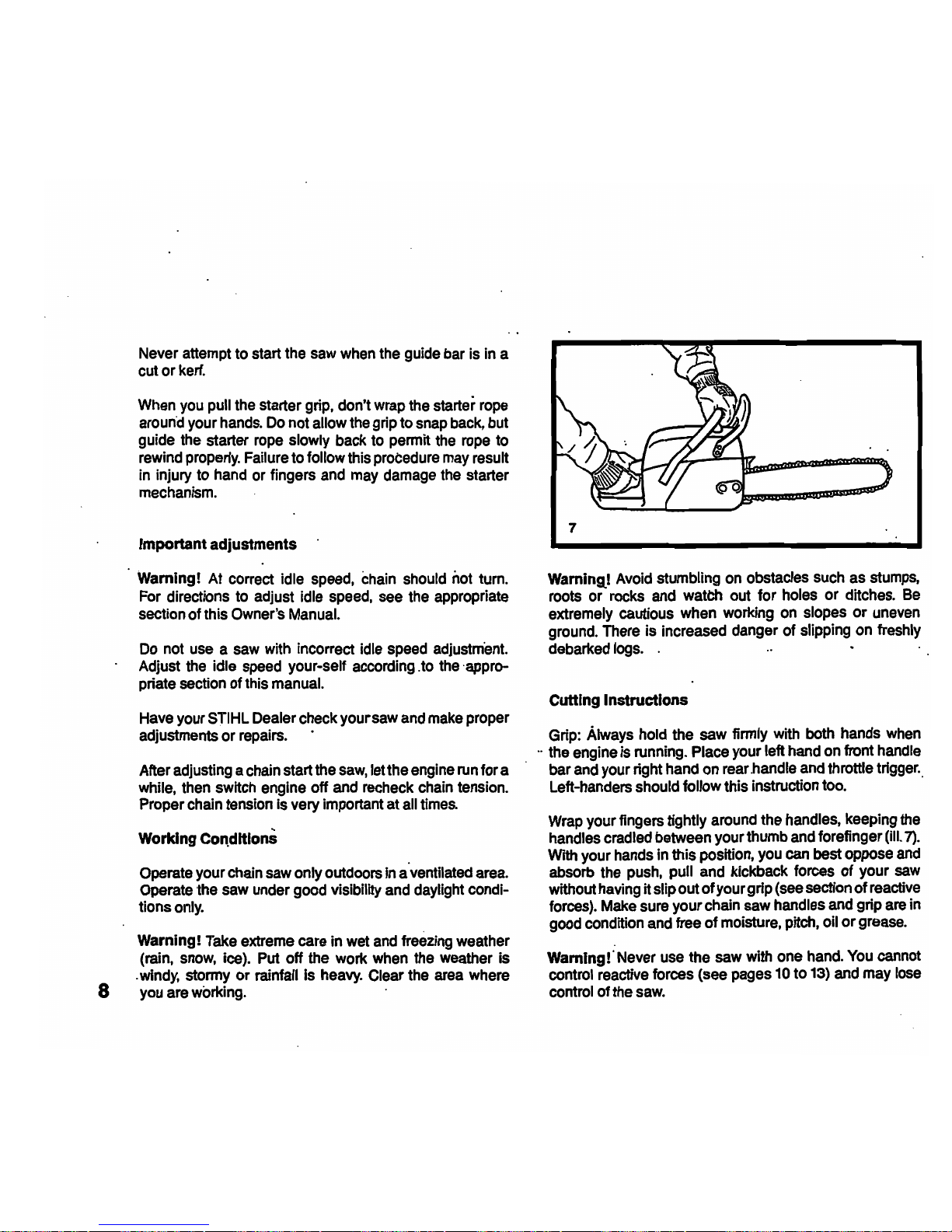
Do
not
drop
start.
This
method
is
very dangerous
because
YC?':I
maY.lose
control of the
saw
(ill. 6).
Place
the
chain
saw
on
finn
ground
or other solid surface
in
an
open
area.
Maintain a good
balance
and
secure
footing.
Be absolutely
sure
that guide bar
and
chain are clear of
you
and
all
other obstructions
and
objects,
including
the
ground:
because
when
the
engine starts
at
starting-
throttl~,
engine
speed
will be fast
enough
fOr
the
clutch to
engage
sprocket
and
tum the
chain,
which
may
cause
kickback
to
occur.
Engage
the
chain
brake
when
starting a
QuiclCstop
model.
(see
chapter
"Chain Brake"
in
your Owner's
Manual).
7
Page 9
8
Never attempt to start the
saw
when
the guide
bar
is
in
a
cut or
kerf.
When
you
pull
the
starter grip, don't
wrap
the starter
rope
around
your
hands.
Do
not allow
the
grip to
snap
back,
but
guide
the
starter
rope
slowly back to permit
the
rope
to
rewind
properly.
Failure
to follow this
probedure
may
result
in
injury to
hand
or
fingers
and
may
damage
the
starter
mechanism.
Important adjustments
Warning!
At
correct idle
speed,
chain
should
not
turn.
For
directions
to
adjust idle
speed,
see
the appropriate
section of this Owner's
Manual.
Do
not
use a saw
with incorrect idle
speed
adjustment.
Adjust
the
idle
speed
your
..
self according. to the' appro-
priate section of this
manual.
Have
your
STIHL
Dealer check your
saw
and
make
proper
adjustments or
repairs.
.
After adjusting a chain start the
saw,
letthe
engine
run
for a
while,
then
switch engine off
and
recheck
chain
tension.
Proper
chain
tension
Is
very important at
all
times.
Working COl\dltlons
Operate your
chain
saw
only outdoors in aventilated area.
Operate the saw under good visibility
and
daylight condi-
tionsonly.
Warning!
Take
extreme care in
wet
and
freezing
weather
(rain,
snow,
ice).
Put
off the work
when
the weather is
.
windy,
stormy or rainfall is
heavy.
Clear the
area
where
you
are working.
7
Warning,!
Avoid
stumbling
on
obstacles
such
as
stumps,
roots or
rocks
and
watCh
out for holes or ditches.
Be
extremely cautious when working
on
slopes or
uneven
ground.
There
is increased danger of slipping on freshly
debarked
logs.
.
Cutting Instructions
Grip:
Always
hold the saw firmly
with
both hands
when
..
the
engine
is
running. Place your left hand on front
handle
bar
and
your right hand
on
rear
,handle
and
throttle trigger
..
Left-handers should follow this instruction
too.
Wrap
your fingers tightly
around
the handles, keeping
the
handles cradled between your thumb
and
forefinger
(ill.
7),
With your
hands
in this position,
you
can
best oppose
and
absorb the
push,
pull
and
kickback forces of your
saw
without
having
it slip out
of
your grip
(see
section of
reactive
forces).
Make
sure your chain
saw
handles
and
grip
are
in
good
condition
and
free of moisture, pitch, oil or
grease.
Wamlngl'Never
use
the
saw
with one
hand.
You
cannot
control reactive forces (see pages
10
to
13)
and
may
lose
control of the
saw.
Page 10

warning!
Do
not
operate
your
chain
saw
with
starting
throttle.
Cutting
with
starting throttle
does
not
permit
the
operator
proper
control
of the
saw
or
chain
speed.
Wamingl
Never
touch a rotating
chain
with
your
hand or
any
part
of your
body.
Wamlngl
Do
not
cut
any
material
other
than
wood
or
wooden
objects.
Use
your
chain
saw
for
cutting
only.
It is
not
designed
for
prying
or
shoveling
away
limbs,
roots
or
other
objects.
When
sawing,
make
sure
that
the
saw
chain
does
not
touch
any
foreign
materials
such
as
rocks,
nails
and
the
like
(ill.
8).
Such
objects
may
be flung
off,
damage
the
saw
chain
or
cause
the
saw
to
kick
back.
In
order
to
keep
control
of your
saw,
always
maintain
a
firm
foothold.
Never
work
on a ladder,
In a tree
or
on
any
other
insecure
support.
Never use the
saw
above
shoulder
height
(ill.
9).
Position
the
chain
saw
in
such
a way that your
body
is clear
of
the
cutting
attachment
whenever the
engine
is
running.
Stand
to
the
left of cut while
bucking
(see
ill.
10).
Don't
put
pressure
on
the
saw
when
reaching
the
end
of a
cut.
The
pressure
may
cause the bar
and
rotating
chain
to
pop
out of the
cut
or
kerf,
go
out of
control
and
strike
the
operator or
some
other object. If the rotating
chain
strikes
some
other object a reactive force (see
pages
10to
13)
may
cause
the
chain
to
strike the
operator.·
9
Page 11
10
Reactive
forces
during
the
cut,
including
kickba-*
WARNING!
Reactive forces, that
may
occur during
any
cut are kick-
back,
pushback
andpull-in.
Reactive forces
·can
··be
dangerous!
In
any chain
saw,
the powerful force
used
to
cut
wood
can
be
reversed
(and
work against the operator).
If the rotating chain is suddenly stopped
by
contact
with
any solid object like a log or branch or is pinched, the
reactive forces Instantly
oCcUr.
These reactive forces
may
result
in
loss of control which
may,
in
tum, cause serious
or
fatal injury.
Anunderstaiidin~i
of the
cauSes
of
these
reactfveforces
may
help you
aVoid
loss of control.
The
most
common
reactive forces are
':"ldckback,
-pushback,
-pull-in.
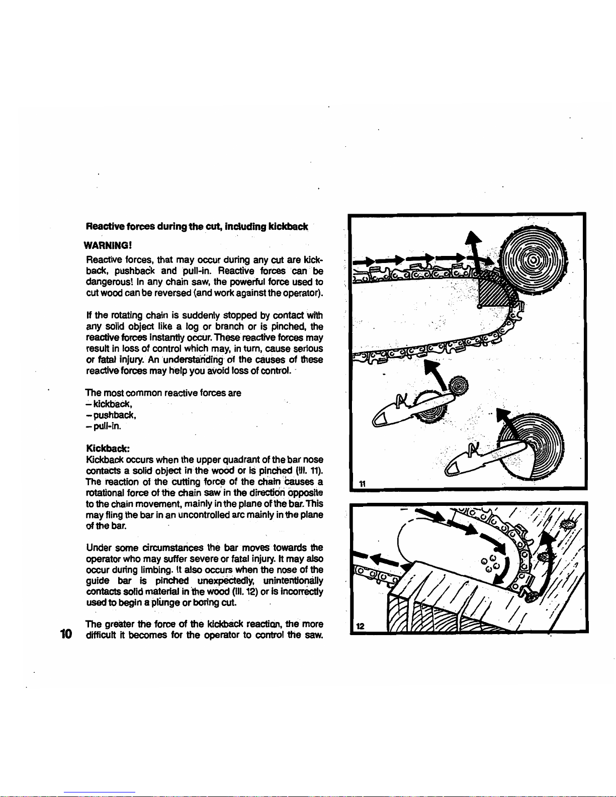
Kickback:
Kickback occurs
when
the upper quadrant of the bar
nose
contaCts
a solid object
in·
the
woOd
Or
is pinched
(III.
11).
The
reaction of the cutting force of the chain 'causes a
rotational
force of the chain saw'in the directidn
Opposite
to the
chain
movement, mainly in the plane
of
the
bar.
This
may
fling
the bar
in
an
uncontrolled arc mainly
in
the plane
of the
bar.
Under
some
circumstances the bar
·moves
towards the
operator
who
may
suffer severe or fatal
injury.
It may also
occur during limbing. It also occurs
when
the nose of
the
guide bar is pinched
unexPeCtecDY,
unintentionally
contacts
sorld
material
in
the wood (ill.
12)
or is Incorrectly
used
to begin a plunge or
bOring
cut.
The greater
the
force
of
the kfckb8ck reaction, the
more
difficult it becomes for the operator to controf the
saw.
Page 12

.
...
..-
~
.
Many
factors influence the occurence
and
force of the
!kickback
reaction.
The
~
of
bar
and
saw chain you
~
~
is a factor in the force of
ttie-klCkback
reaction.
;
The
speed
of
~
~wh"
the
cutter
contacts
the
object.
.,'
_
~"
<.~,
),' -
'_'.
".
-
,Kickoaclfforces'Inereuewlth
the
raleOf
Impact·
il
>
\::..:
_"M~:
','
,'i-
~
''''-''f
~_ct~~
u.;
~ose
of
the
b,ar
and
the
~fo.~·{see-IIt-11).'.-
':
,.:
'
".'
KickbaCltVmosfproriOunc:ed
'"1M
upper
quadrant of the
~bar
ROSa,
,,'.'
SOme
STlHL
chain types are designed to reduce kickback
forces.
The.cJeptb.aauges:'
Improper
lowering
of
the
depth gauges also
Incre~
the
chanceofa~
:1
The
sharpening
condition:
warning!
Adun
orimproperty sharpen.ed
~
may Increase the
risk
of
kickback.
Always cut
with
a property sharpened chain .
",
Devices
for
reducing
the
risk
of
Idckback
Injury
STlHL
has
developed a chain stopping system to reduce
the
risk
of injury
In
certain kickback sItuations.Jt ~ called a
Quickstop.
""
.,
The,
,Quickstopis,
av-.i~
as
an
optiQn on most STIHL
chain.saws.
' .
Wti.
a~
oc:curs
the
guide.bar
may
iotate
around
the
front
handle. H
the
cutting position
Is
such that
the
operatOr's
left
hand
is
gripping
the
froI1t
hBrldle
behind
the
hand
guard,
and
if the left hand rotates around the front
handle and contacts the front:
hanef
guard, which is the
,Quickstop activating
lever,.
this contact
will
activate the
. Quickslop
and,~
the;chaln'(~
ill 13). '
\
The
~.brake
of
some
STlHL
chain
saws
is additional
.
self-activated
by
fnertia.·
see
appropriate.
ct1apler
"ChaIn
Brake"dt
yo~r
<?wner's
ManuaL
' , ,
,
Kickback
tendency increases as
the
radius or size
of
the
guide
bar,
noseAncreaseLSTIHL has
developed
guide
bars
with
small
nose
radius.
These
bars. are designed to
reduce
the
kfckback
tendency
and
are available, as
an
option.
STlHL
taas~
d~~
chains
whoseconftgu,r~
are
~ned.to
reduce.~
forces. These.
chains
are
available
as
an
option.
.
Warning!
Chain
saw
kickback
may cause serious or fatal
'injury.
To
reduce the
risk
of
kickback
injuries snHL'recommends
that
you
equip
your
saw·With
a narrow),ose
bal,
lOW
profile
chain
or
oth8r
chatn
deSIgned
to
reduce
'kickback
forces,
..
~aS11HL~.
Warning I
~o
Qulcksk;Jp
or
ch~
~
de~
.prev&n!SkIckback.
These
devices
are
designed only to stop the chain.
if
acti-
vated,
in.
certain kickback
situations.
In
~r
for the
Quickstep
to
reduce
the
riSk
of
'kiCkback
inj~,
it
mUst
be
P"'~
mai~
anei'ln
gOod
working
order.
In
addition,
there
must be
enough
distance between
the
bar
and
the operator to ensure that
the
Quickstop has
sufficient time to activate
and
stop the chain before poten-
tial contact
with
the
operator. '
11
Page 13
13
Warning!-
Even
if your
saw
is
equipped
with a
Quickstop, a n8J'l'OVl
nos.e
_~
or
~uced
kickback
chain,
this
does
not guaran-
tee'th8t'you
'!III
not
be
Injuied by
kfcftback,~and
therefore
always-
observe
aU
safety
prec8utlons
to
avoldldckback
situations.
To avoid kickback
The
best'
protection
-from
perSonal
injury that
may
result
from
kickback·
Is
to
avoid
I<k:kb8Ck
Situations:
. ,
'~
1.
~kI
the
chain
saw
firmly
with
both hands andlnalntain
a
secure
grip.
2.
Be
aware
of1he
location
Of
the
guide bar
nose
at
aU
timeS.
-':'
3. Never bring the nose
Of
the guide
bar
In
COntactwfth
any
.
~bject.
Do
not
cut limbs
with
the nose of the guide bar.
.
Be'~DIhi
car8fulWhti
smalftb'
h'nmbS.
sman
SIze
~.'.1
..
ug
, brustf
antf'saplIngs
which
may
eaSily
catch the
chain.
.
~.-
,,'
."
~',
.
4.
Don't
overi8ach.
i_
12
5. Don't cut above shoulder height.
6.
Begin
cutting and continue
at
fuU
throttle.
7.
Cut
only
one
log
at
a
time.
8.
Use
extreme
caution
when
re-entering
a-previous
cut.
, • > ~
9.
Do
not attempt plunge cuts (see
page
18) if
you
are not
experienced
with
theSe
cutting
techniques.
10.
Be
alert for shifting
of
the
log
or other forces that
may
cause
the cutto
close
arid
pinch
the chain.
11.
Maintain saw chain properly. Cut
with
a correctly shar-
pened,
properly tensioned chain at
all
times.
12. Statid
to
the side
of
the cutting path of the
ch8Jn
saw.
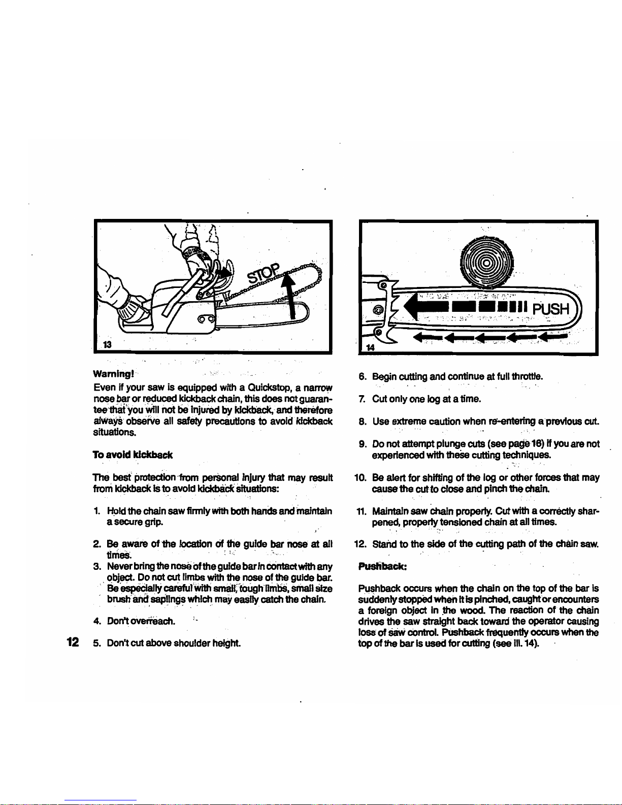
Pusliback:
~hback
occurs
when
the
chain
on
the
top
of
the
bar
is
suddenly stopped
when
Ills
pInChed.
caughforencounters
a foreign object in
..
wood.
The
reaction
of
the
chain
drives the
saw
straight back toward the operator
causing
loss
of
saw
cOntrol.
PUshback frequenttyoccws
when
the
top of the bar
Is
used
for cutting (see
111.14).
Page 14
_ '
To
8VoIcI
puShback
1.
Be
alert to forces or situations
that
may
cause
material
to
pinch the
top
of
the
chain.
2.
rlc?
notcut~reth~
one
log at a time. ' ,
3.
Do
not twist the •
when
withdrawing the
bar
from
a
plupge
cut
or
und8r~
cut (figures 25
to
'Zl
and
33,
pageS
16, 17 and 19),'
becaUse
the chain
can
pinch.
'. ,
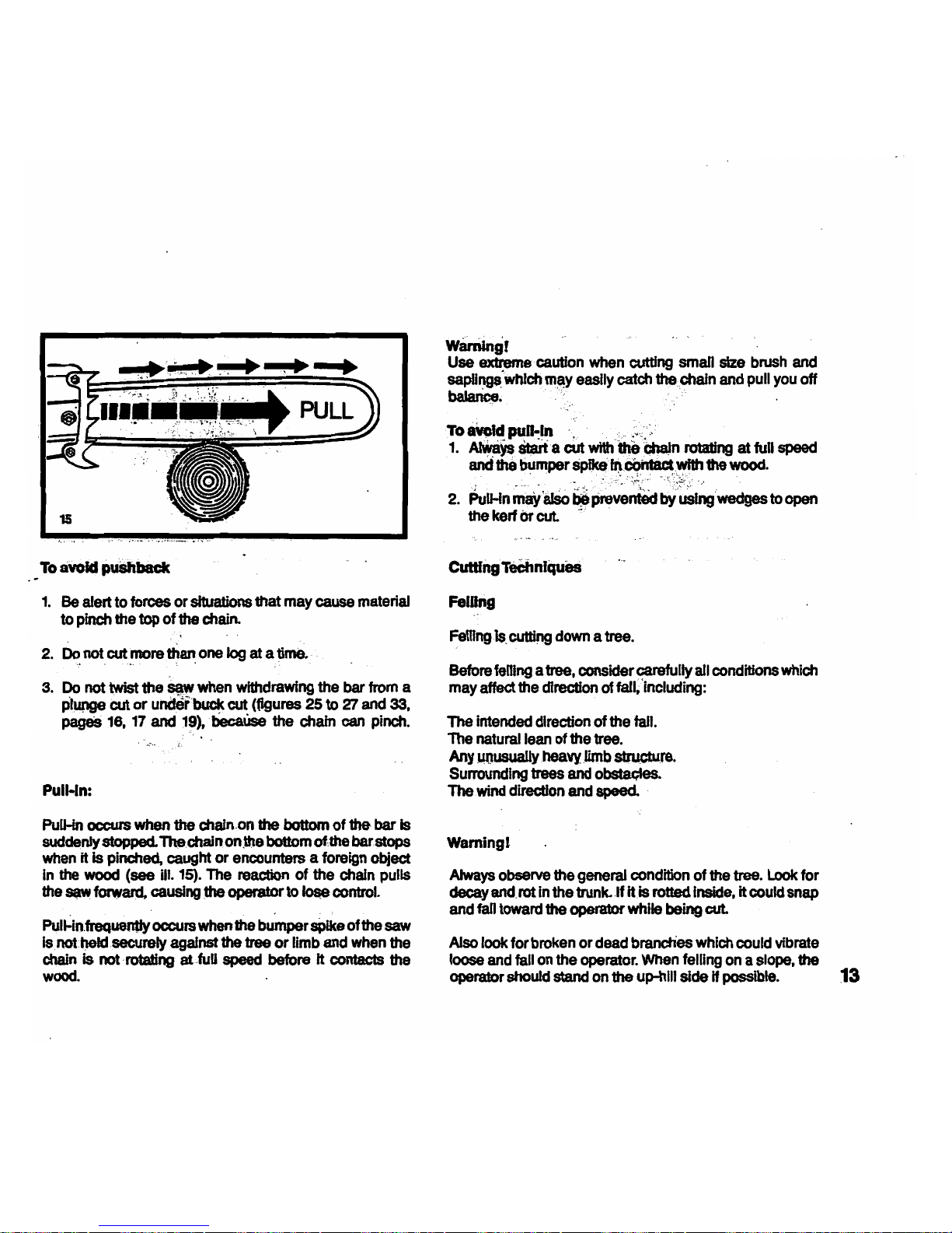
Pull-ln:
PuU-ln
occurs
when
the
chain
,on
the bottom of the
bar
Is
suddenly
stopped.
The,chain
on~8
bottom oUhe bar stops
when
it
is
pinched, caught or encounters a foreign object
In
the
wood
(see
HI.
15).
The reaction of the chain pulls
the
S(lW forward, causing
Ute
operator to
Iotle
control.
Pull-4n.frequently
occurs
when
the
buR.per
sPIke
of the
saw
Isnot.I)eId,secureIy against
the
tree or limb
and
when
the
chain
is not'rotating atJuU
speed
before It contacts the
wood.
WBmlngf
Use extreme . caution
when
cutting small size
brush
and
sapOF.'9$.'
whfch
m~y
easily catch the.chafn
and
pull
you
off
balance.
'.
To
aVoId
pu~1n
','
... ' _",,','
1.
~
St$rt'a
cut
with
'the
Ci1aJn
rotating at
full
speed
and
the
bumper
SpIk8'~,COhtactwlth
1he
wood.
2.
PuU-in~8ISo~pre~~~:~~:_toopen
the
kerf
Or
cut.
-' '
Femng
is,
cuttll'I9
down a tree.
Before
femng
a tree, consider carefully
afl
conditions
which
may
affect the direction of fall/including:
The
intended direction
of
the fall.
The
natural
lean
of the tree.
Any
MOusuallyheavylimb
atru.cture.
Surrounding
trees
and
obstaQles.
The
wind
direction and speed.
Warnlngt
Always
observe the general condition of the tree.
Look
for
decay and,rot
in
the trunk-If
iUs
rotted inside, it could snap
and
faD
toward the operator while being cut.
Also look for
broken
or
dead
brandies
which
could vibrate
loose
and
fall
on
the
operator.
When
felling
on a slope.
the
operator
should
stand
on
the
up-hiIJ
side
H possible.
13
Page 15

When felling in the vicinity of roads, railways and power
lines, etc
..
take extra precautions (see ill.
16).
Inform the
police,
u1ifity
company
or
railway au1hority before begin-
ning
to
cu1
.
When felling, maintaJn a distance of
at
least·
2'h
tree
lengths
from
the nearest person (see ill.
17).
Note:
14
The noise of your engine may drown any warning call.
Felling
Instructions:
Firs1
clear the tree base and work area from interfering
limbs end brush and clean its lower portion
with
an
axe
(ill.
18).
.
Then, establish. a path of escape and remove all obstacles.
This path should be opposite to the planned'dlrection of the
fall
of
the tree end at a
4S.
angle (ill. 19). An alternate
path must also be selected. Place all tools and equipment
a safe distance away from the tree,
bu1
not
on
the escape
path.
Page 16

20
H
ttle.~,,~
large
~
~
cut
Into
the
largest
. -.
~utbeSSes
vertically;
first,
(hori,zontally
next)
and
remove
(Hl20~
,,;
~
d8t8rmiil8,
the
placement
of
the.feUIng
note."
(Ul2t).
1J1e'~
~
~
,poper:tY
,placed
determ1r)es
the
directioh
In
whJchthe
treewiiUaLIt
Is
made perpendicular
to
the
nne
Of
f8n
&net
shOUld
be.
close
to
the
groUnd
as
possible. Cut the
felling
notch
to a dePth
of
abOut
one-fifth
to one-fourth of the trunk diameter (Ill 22). It should be
In
no
~
higher than it is
deep.
Make the felling notch
very carefully.
Begin
the
felUng
cut slightly higher than the
feDing
notch
and.
ora
the
opppsite side of
tIMI
tn!e
(ill.
.22).
Then
cut
ho~l)I~h:toward$
~
~,n,g
notch. Apply the
chab1
saw
with its
spikes
dlrecdy
t;MlhIndthe
~
portion
of
wood and cut toward the notch (ill
23~
Leave
approx-
imately
'ho
.o1.the
~
dlam_~
~n.c;ul
This is
the
hln.ge
(III.
23}.'Ofi'i1ot
Cut
thrOugh
the
hinge
_use
you
Could
lose control
of
the direction
of
the
faIL
Drive wedges into
the
felfll'l9.
~t ~ ~
to
COI1tmI
the
direction
oftha
ftdl.W~es
should be ofw9Qd.
Ught
alloy
or
plastic-
never
~'~
Which
can
~
kIckback,and
~
tothechala
22
Hinge
---i~
Felling
notch
-*
Hinge......,........,H
Felling
notch
15
Page 17

16
24
A'iways
keep
to
the
side of the
f8Jling
tree.
When
the tree
starts
to
fall,
shut off
the
engine.
WIthdraw
the bar
and
walk
away
on
the pre-planned escape
path.
Watch
out for
failing
limbs.
Warning! :
Be
extremely careful with partially fallen trees
which
are
poorly
supported.
When
the tree
h~;or
19r
~
other
reason
does
not
fall'
completelY,
set"the
saw
asfde'and
pull
the tree
down
with
a cabIe·wlnch,btockand tackle or tJactor.lf you
try
to
cut
it
down
with
your
saw,
you
may
be
injured.
Sectioning Method
warning!
.
Felling
a tree that has a diameter greater than the
length
of
the
guide bar
requl~
use
of either the
sectioning
or
plunge-cut
method.
These methods' are
extremely
dangerous
because they
InvolVe
the
use
of the
nose
of
the
guide
bar
and
can
result
In
kickback. Only
property
trained professionals should attempt· these techniqueS.
25
Forthe
tteeHOriing
methOd
(HI.
24)
make
the first cut
with
the
guide bar fanning
tn
toWard
the·
hinge. Then,usmgthe
bumper spike
as a pivot, reposition the
saw
for the next
cut.
Avoid
reposftioning the
saw
more
than
necessary.
When
r8poSltiori!rig
fci
the
11Et~
~
ic8ep
'the guide
~r
.i¥!Iy
engaged
in the
kerr
to keep
the
fettlng
cut
strafght
If
the
saW
begins
to
pinCh.
inSert
a
w8dge
to
open the
cut.
On
the
~
cut.
dO
not
cut
the
hinge.'
Plunge-Cut
~
Tmber
haVIng
a diameter
more
than
tWice
the
!ength
Of
the
gUKJe
bar
reqUires
the use of the
plunge-(x.it
method
before
making
th.e
f8lHngcUt . .
First.
cUt
a large. wide
nOtch.
Make a plunge-
cut
In
the
center of the
notCh.
. . .
The-
plunge
cut
is
made
with
the guide' ~ nose.
BegIn
the
plunge.
cUt
by
'applylitg
the
lower
portiOn
of
the
guide
bei
nose
to
the
tree
at
an
angle
(ill.
25)~
Cut until
the
dePth
of the kerf
Is
about the
same
as
the width
of
the guide
bar
Page 18

26"
28
~
.
\A)
~
29
(m.
26).
Next,
align
the saw
In
the direction
In
which the
recess
is to
be
cut."
.
WIth
the
ssw-
at
fulithrotUe, insert
th8
guide bar
in
the
trunk
(II!.
27).
Enlarge
the
plunge
cut as
shown
In
illustration (ill.
28).
warning
I
There
is
an
extreme
danger
of
kickback
at
ttris point.
Extra
caution
must
be
taken
to
maintain
control
of1he
saw.
To
make
the
felting cut,
..
follow the· sectlonfng
rnettiod
described previously (ill.
29).
H you
are
inexperienced with a
chain
saw prunge-cutting
should
not
be
attempted.
Seek
the help
of
a professional.
Umbing
Umbing . is
removing
the
branches
from
a fallen tree.
WBmIngl
There is an
extreme
danger
of
kickback during the limbing
operation.
Do
not work with the hose
of
the
bar.
Be
extre-
mely cautious
and
avoid contacting the
log
or other limbs
with
the
nose
of
the guide bar.
00
not stand
on
a log while Ilmblng it - you may slip or the
log
may
roll.
17
Po
Page 19

18
Start
Umbing
by
leaving
the
lower
limb$
to
support
the
log
off
the
ground
(ill. 30).
Always
cut
f~
the
top of the
limb.
Do
not
underbuckfreely hanging limbs
•.
A pinch
may
result
or
the
limb
may
fall,
causing
loss
of
control.
If a
pinch
occurs,
stop. the
engine
and
remove
the
saw,
by
lifting the
limb.
warning!
Be
extremely
cautious
when cutting
limbs
under tension.
The
limb
could
spring back toward
the
operator and
cause
loss of control of
the
saw
or injury
to
the
operator.
Bucking
Bucking
is
cutting a
log
into
sections.
Warnings!
1.
When bucking,
do
not
stand
on
the
log.
Make
sure
the
log
will
not
ron
down-hill. If
on a slope,
stand
on
the
up-
hill
side
of
the
109
(see
Ill.
31).
Watch
out
for
rolling
logs.
2.
Cut
only one
log
at a time.
3.
Shattered
wood
should be cut
very
carefully.
Sharp.
slivers of
wood
may
be
caught
and
flung
in
the
direction
of
the operator of
the
saw.
4.
When
cutting
small
iOgS~
Use
8SaWhorae-(iD.
32).
NeVer
permit another
person
to
hold
the
log.
Never
hold
the
log
with
your
leg
or.foot.
5.
Logs
under straln,'require
sPecial
attention to
prevent
the saw
trpm
pinch1n.g
•.
The
fifst cut·is
made
on
the
compression
side to relieve the stresS
on
the
log
(see
III.
33~
34).
The
bucking
cut is
thEm
made
as
shown.
If the
saw
pinches,
stop
the
engine
and
remove
it
from
the
log.
6.
Only
properly trained professionals
should
work
in
an
area
where
the
logs,
limbs
Bn.d
roots
are
tangled
(i.e. a
Page 20

1.
Refoeving
cut
33
. 2. Cross art
34
blowdown area, ill. 35). Worldng
in
blowdown areas
is
extremely hazardous.
7.
Drag the logs into a clear area before cutting. Pull out
exposed and cleared logs
first.
Maintenance BDd Repair
Never operate a chain saw that is damaged, improperly
adjusted
Of
not completely or securely assembled. Follow
the maintenance and repair.instructions
in
the appropriate
section of your
Owne~s
Manual.
warning!
Always stop the engine and make sure that the chain is
stoppe.d
before doing any maintenance or repair
wor!<
or
cleaning the saw.
Do
not attempt any maintenance or
repair
wor!<
not described in your
Own~s
Manual. Have
such work performed at your STlHL service shop orily.
MAINTAINING
AND
STORING
THE
SAW
Keep the chain, bar and sprocket clean and lubricated;
replace worn sprockets or chains.
Keep the chain sharp.
You
can spot a dull chain when
easy-to-cut wood beccmes hard to cut and bum marks
appear
on
the wood.
Keep the chain at proper tension. Tighten all nuts, bolts
and
screws
except
the
carburetor
adjustment
screws
after
each
use.
Keep
spar!<
plug
and
wire connection tight and clean.
Store saws
In
a high or locked place, away from children.
19
Page 21

20
Mounting Guide
Bar
and Chain
Top:
Backing off tensioning
nut
Bottom:
Locating
the
guide
bar
The guide bar and Oilomatic chain are supplied separately
for safety reasons.
To
mount them, first unscrew the coliar nuts
(1)
from the
stud bolts (2) and take off the sprocket cover (3).
Now back off the chain tensioning
nU1
(4)
- below the stud
bolts
(2
) - by tuming the tensioning screw (5) counter-
clockwise to the end of
Its thread.
Top: FJtting
the Ollomalic chain
Bottom: Cutting
edges
face
the
bar
nose
Locate slot
of
guide bar over the stud bolts (2)
so
that the
lug of the tensioning
nU1
(4) engages in the lower fixing
hole (6).
Starting at the chain sprocket, place the Oilomatic chain
on
the guide bar so thal cutting edges on the top
of
the bar are
facing
the
bar nose
(7).
Fit chain sprocket cover (3) on the
stud bolts
(2)
and tighten coliar nuts
(1)
temporarily by
hand. .
Page 22

Top
: Tensioni
ng
the Oilomatic chain
Bottom
:
TIght
en
collar
nuts
secu
rely
Now tension
the
Ollomatic chain by
tumlng
the tensioning
screw (5) ctockwise. making sure
that
the drive link tangs
are lined
up
with
the bottom groove
of
the
bar
. Hold the
bar
nose (7) up
tum
tension screw (5) until
the
Oilomatlc chain ·
is
pmperly
seated
on
the
underside
01
the
bar
. While stili
holding
the
bar nose
uP.
tighten
the
collar
nuts
(1)
securely.
Ch
ecking chal
n
te
nsi
on
The Otlomatic chain
Is
correctly tensioned when is
fits
snugly on the underside
01
the bar
1;,"1
can stili
be
pulled
easily around
the
bar
.
21
Page 23

22
Fuel
Fuel
tank
cap open
You
two-stroke engine is powered by a mixture of gasoline
and engine
011.
Only
regular
gasoline
may
be
used.
Never use high
octane gasoline as it contains benzol which would per-
manently damage the carburetor diaphragms.
Only use STIHL two-cycle engine oil or
other
branded two-
cycle engine oils for mixing. The mix ratio
Is
1: 40
(1
part oil
to
40
parts regular gasoline) with STlHL two-cycle engine
oil
or
1: 25
for
other
branded engine oils.
Important:
Always
shake
mixture
In
fuel
can
vigorously
before
fueling.
-
Chain Oil
Oil
filler
cap
open
The
service
I~e
of
the
cutting attachment (Oilomatic chain
andguide
bar) depends on'good lubrication and the quality
of
the
lubricating
011.
Never
use
waste
011
for
this
pUrPosel
Always use
the
chain lubricating oll.approved by STIHL
and
appointed dealers.
If
special chain lubricating oil is not available, one of the
high-duty, Single grade engine oils listed below may be
used
In
an
emergency,
d~nding
on the outside tempe-
rature.
Outside temperature + 1 O'C
...
+40"C: SAE
30
Outside temperature +
10'C
...
-10·C:
SAE
20
Outside temperature
-10·C
...
--30OC:
SAE
20
W or
SAE
10 W
Always top up with chain
011
when you refuel. Carefully
clean the area around the filler caps before opening and
make sure that no dirt falls
inlo
the
tank
while you are
refueling.
Page 24

Helpers Handle
Knocking out blanking plug
,--------~~~-~
For safety reasons and
to
Improve cutting accuracy ~ is
.. advisable
to
use
the
helpers handle
(1109
660
2500) n your
saw
is equipped with a 105 em
(42
In)
or
longer cutting
attachment.
With
the
handle fitted a second man can safely
assist
the
saw
operator in handling
the
saw.
When the helpers handle Is being
used
the
non-cutting
side
of
the
saw
chain
must
always be covered
by
a guard
rail which matches
the
bar
length.
To
assemblethe helpers handle, first
knockoutthe
blanking
plug (3) In
the
slot
(1)
at
the
bar
nose
(2).
Then
tum
the
clamp nut (5) (star knob) counterclockwise to rotate
the
head
of
the
clamp bott (4)
so
that
it
fits through the slot
(1)
in
the
bar.
The
head
of
the
clamp bon (4) is turned through
90" when
the
clamp nut (5) (star knob) Is tightened and
thus secures
the
helpers
handle
(6) against
the
guide
bar
(2).
To
attach
the
guard rail (7), first ffl
the
mountfng
hardware
to
the
CI8J1kcase
and
the
helpers
handle
and then place
the
guard rail
In
posiIJon.
Top:
TIghtening
the
clamp
nut
Center:
Mounting
hardware
fitted
on
bumper
spike
Bottom:
Guard
rail
in
posttion
___
6
'-'-
____
1
23
Page 25

Starting
Stop
switcl1
away
from
"STOP "
"
To start the engine, place
Ihe
chain
saw
on the ground,
make
sure you have a finn foothold and
the
saw chain is
clear
of
all obstacles and
the
ground. Bystanders must
be
kepI well clear
of
the
general
work
area
of
the
saw.
Starting
procedure
1.
Move
stop switch
(1)
away
from "
STOP".
2.
If
the engine is cold, move choke lever (2) to
"Choke
".
If
the
engine
is
wann
or
has only
been
stopped for a
brief
period, move choke
lever
(2)
away
from"
Choke".
3.
Set
throttle trigger (3)
10
starting throt1le position by.
pressing the
safety throWe lock (4), throttle trigger (3)
and
starting throttle lock (5) In
thai
order.
Le\go
ofthrotUe
trigger (3) first
and then
the
starting throtUe lock (5).
If
you have an O9OAVfirsI squeeze
the
throttle trigger (3)
and
press In
the
starting throtUe lock (5) . LeI goofthrotUe
24 trigger (3) first and then the starting throtUe lock (5).
Top
: Choke lever
In
" Choke" position (cold start)
Center: Choke lever away
from"
Choke" position (warm start)
Bottom: Starting throttle position
Page 26

Pressing
the
decompression
valve
4.
Hold
the saw firmly
on
the ground with your left hand
around the handlebar (6) and put the toe of your right
foot into the rear handle and press down.
5.
Press the decompression valve (7) with the
th
umb
of
your left hand. Pull the starter grip (8) slowly with your
right hand until you feel the starter engage and then
give
~
a brisk strong pull.
The starter rope should not be pulled out more than
70
em
(27 in) as there is otherwise a risk of it breaking.
Do
not allow starter grip (8) to snap back. Guide it back
vertically so that the starter rope can rewind correctly.
6.
As
soon as the engine is running, release the decom-
pression valve
(7) and immediately disengage the start-
ing
throttle lock
(5)
by briefly squeezing the throttle
trigger so that the engine can settle down
to
idle speed.
7.
To
stop the engine, flick the stop switch (2) to the
"STOP"
position.
Top:
51.rting
Center:
Idle
position
Bottom:
S10p
switch
In
"STOP"
position
*"
__
8
•
,
25
Page 27

;
other
points to
beobserved:~~·l~
..
,
~
engine:
The choke lever:is
mectianl~
"
&)ritJ
i~<
the
.·
~
retor's choke valve. The:
dlOki
:V8(Vltis
Closi,cfWhen
the
choke lever
is
00
..
chOke
t"skfWiiQ'n
the ,
CilOke
lever
is
moveda~ay,
from
.~
~;~:~,,~;
::~
~:,
;,
·',Yi~
:,
:;:,~~".:~
:,
:.::~1}
:
; . ,
~
-"'. I
I,'
~en
'
Starti~
a-cold fihglne
on~~p
~~'~~:~ve~
in
the " Choke
II
poSition
until the
engine
~bj$~:ftie.
Then
open
choke fully -
chOICe
rever'away
·
~tCfWk8"
-
ev,en
if the ,engine
stops
and
you
have ·to,·repeat:,thestartfng
prcx:edur~l.the
choke
lever
~.~iJl#:l~··.~·~
pqsition.
. the combustion chamber
wllfftOQd8hd
'
_II'''~ri8/
.
~~
.~'::
: :·tt:~;~;·";
~::,:.:51>'··:
··:~;:
~(
~
If
you
moved
tile
choke lever
8Wlly!
·
frOJtli]hj
~
~QiQke
..
position
after
~~j~Qgtnefired
B!td~
"
~a~~~((:~
·
~ot
run
after
sevEDI'"
, H
is:alMQAU'~
:In~
SUCb
a
_t" o
.
~
.. " . : ••
~t
.
-·'
~"'
~ '.':~
'
-'1":~
~
:-'.
·'·
,,;,"'
~'·
""
:
C8$~.
re_'~,1ty9fUh!'~P!qg~~~~~s
tionch~bY)~~gtht
..
~;~~~
~
~~n
. the
starter:WiIti:the
"
ric'".
"StiU'remoYed '8rid:,1Iuf"8lO
~~11ii"
,·
':
~~
;~
~;sTbpT~~~.
~!p
,i
;
y~q~
"
,
~,~:~
,
mOv8:~'~e
lever
~froril
uChQk~~~f-
,
__
n
"e
qlneJfi(cold, -
and
set the '
throttle
triggerJp,:1I18SJ8rt1ng
:';
tt1roUle'po$ition.
."'·:
,~'
/.: :
,:~,~~::
~~;+t:~~
:'
I~
the"choke slightly after
..
~:g:,:mq
v~~r
t.Ocenterposition.Alloweng,
.
ne
"
to
wsnntyp'fo
r:j
1)rlet:P8rfod,
at
haIt.;;tfli'ottIe.
Then
move
choke
1eY8t'8Wi-fioRj
~ChOke"
and
diSen
' the start-
(n9th~
",.
~.bck
"
' ,
:,,
'
..
:
'>
.
~:
.
"
",
,'
',~./
i>
r.j:;.
.
:
:->~..
.
:~>.~':.~:
"
:-:"
..
A,
f)ew
engin8
::
o.~
·
W_~
been
run
until
~~~~~k
is
dry
will
not
start
fI!St~8fter
fueling becauS"1hecar-
buretor's
dlaphragm
~
pqtiJp
only
deDvers
sufft~J~el
26 after the engine
haS
b88atUmed
over, several
timeS:
, '"
Page 28

Oil quantity control
Top:
1 = Adjusting screw
2 =
Counter
nut
Bottom: Loosening
the
counter
nut
At
the factory the chain oil supply of the oil pump is adjusted
to
the standard cutting lengths
of
53
em
(20.9 in.) bar for
090, 090
AV,
90
em
(35.4 In.)
bar
for
090 G. When using
longer guide bars
rt
is possible to adjust the
011
quantity
according to the bar length used by means of the provided
adjustmem screw.
Before readjusting the oil quanttty remove
Mer
cover and
fllter, flrst, however, close choke shutter (posrtion
"0")
so
that no dirt can drop Imo the carburetor.
.
Top:
. Adjusting
the
oil quantity
Bottom:
Countering
The adjusting screw for regulating the oil quantity is located
althe
rear-wall of the
011
tank and is coumered with a hexa-
gonal nut. Hold adjusting screw
wlth fork wrench SW
10
and loosen counter nut wrth second wrench . .
When tuming the adjusting screw to the left - counter
clockwise - more
011
Is supplied and when tuming to the
right less
011
is supplied. Tuming the adjusting screw '/3 of
a tum corresponds approx. to the necessary change of oil
supply which is needed for the next longer bar length.
27
Page 29

Cutting Attachment
, O
Ulntet
borings
2
Gente,ring
borings
The cutting attachment
of
a chain saw consists of the guide
bar; saw chain and chain
sprocket
GuJdebar
The nose and underside
of
the guide
bar
are subject
to
a
particularly high rate
of
wear
. To avoid one-sided wear, tum
the bar around every
time
you resharpen or replace the
chain. Regular cleaning
of
the
011
Inlet holes and guide
bar
groove is also important. The
bar
can be examined for signs
of wear
at the same
time.
A minimum
bar
groove depth
of
7 mm (0.28 in)
must
be
maintained in order to prevent the drive
Unks
fouling the
bottom of the groove (the heels
of
the culler and tie strap
would no longer locate on the guide bar track
).
This depth should be measured
at
the point where the
bat
is
stressed
mOst
,
I.
e.
the
bar
noee or:
D'..!romatic
bars
and
the area where most
of
the cuttiilg is done
on
RoliomaUc
bars. The guide bar must be replaced.
1f
the minimum depth
28 cannot be maintained.
On Roliomatic guide bars the bearing
01
the nose sprocket
must also
be
lubricated at regulated intervals with the
appropriate grease
gun.
Lubricate at least once druly under
normal operating conditions. Only use a high grade grease
for refilling the grease gun. e.g. refill lUbe
0781120
1111
.
To lubricate, place chain saw on its side so that the bar
nose is firmly supported. Clean the grease hole and pump
in grease while slowly pulling saw chain around
bar
(sprocket rotates) so
thai
bearing is uniformly filled. When
grease emerges
at
the hole on the other
sid!>
of the bar or
around
!be
nose. sprocket, repeat the procedure on the
other side.
The sprocket nose bearing should
be
greased more often
ff
the
cutting
attachment is used
in
damp conditions, e.g.
working
in
snow. AfII!r finishing cutting work the sprocket
nose should be .thoroughly greased from both sides
to
force moisture
out
of the bearing and prevent corrosion.
Chain
lubrication
Never operate the chain
saw
without proper chain lubrica-
tion. Check operation
of
chain lubrication and level in 011
tank before starting work.
Hold chain saw with mounted cutting attachment over a
light background. Take care, the Ollomatic chain must not
touch the ground.
i.
e. keep H at least
20
em (8 in) clear of
the ground. Run the engine with haH-throttle position.
ff
an
increasing patch
of
oil can be seen, chain lubrication
is
operating correctly.
Page 30

Checking
chain
lubrication
Wom
chain
sprocket
Breaking
In
OHomatic
chain
Every new chain
has
to be broken
In
for about 2 to 3 mInu-
tes. Ample chain lubrication is essential during this period.
After breaking
in
, stop
the
engine, check chain tension and
adjust if necessary.
Correct
chain
tension
The Ollomatic chain must always be slackened off after
finishing cutting
work
A chain properly tensioned when
~
is warm would, when the temperature drops, be subjected
to such great contnaction stresses that
~
would break and
also damage the crankshaft and bearings.
The Oilomatic chain must, therefore, always be tensio
ned-
w~
the engine switched off - before you start cutting.
Chain tension is correct
In
the cold condition when the
chain fits snugly
on
the underside of the bar and can still
be moved along the bar
by
hand. Extreme care must be
!eken as ·the cutting edges are very sharp.
When the chaln saw Is operated at extremely low outside
temperatures a correctfy cold-tensioned Ollorpatic chain
will begin to sag noticeabl)i"as H warms up to
noimal
operat-
ing temperature. The chaln must then be retensioned.
However, the chain must be slackened off again
immedia-
tely after shutting down the saw. This Is necessary to avoid
contraction
stress which would occur as
the
chain cools
down to ambient temperature.
A new chain must be retensloned more frequently than a
used one util h has stretched fully.
Chain
sprocket
The stress and strain
on
the chain sprocket are particularly
high.
~
the
wear
mar1<s
on the teeth are very pronounced
(about
0.5
mm/O.D2
In
deep), the sprocket should be re-
pl8ced. A
wom
sprocket reduces the service life
of
the saw
chain. The chain sprocket should be replaced as a matter
of routine whh every secOnd Oilomatic chain.
n Is
best
to
use two chains alternately
w~
one sprocket. 29
Page 31

, =
Oil
filler
cap
2 =
Manual
oiler
3 = Oil
inspection
window
Alter adjusting hold adjusting screw with a fork wrench
and counter hexagonal nut again wi
th
second wrench.
Thereafter assemble air finer and filter cover again.
In extreme cases (failure of automatic oil pump, heavy
frost etc.) the use of the hand oiler assures sufficient chain
lubrication.
Also during longer cutting periods with longer cutting
lengths the chain
is additionally supplied with lubricating
all by activating the manual oller. Moreover, before
starting
we
recommend to supply
add~lonal
lubricating oil to bar
and chain by activating the manuai olier should the saw
s~
idle at freezing temperatures for a longer period. Thus the
cutting attachment is protected against excessive wear.
The oil level can be-checked at the inspection window
(3).
Always fill up with chain oil before starting work. Check
the oil level at frequent intervals during cutting and top
~
30 up before it drops too low.
Air Filter
Di
sassembty
of
air
filter
The air filter's function is to intercept dust and dirt
in
the
combustion air and thus reduce wear on engine components.
Clogged air
Mers
reduce engine power, increase fuel
consumption and make starting more difficun.
The
airfilter
must
be
cleaned
dally-or
morefrequently
in
very
dusty
operating
conditions.
Before removing the finer, close the choke vaive so that
no
dirt can get Into the carburetor. Unscrew the finer cover
and take
out
the
filter element.
For daily cleaning it is sufficient
to clean the filter with a
soft brush. However,
the
complete' air fitter should
be
washed In clean gasoline at least once a week
and
blown
out with compressed air
IT
possible (Hocked air filters must
not
be
cleaned with compressed air, brushes or rags
).
If
the wire mesh is damaged on either hart of the air finer
(or
If
the fiocking is damaged), always fit a new part.
It
is advisable to carry a spare filter with you at ali
Umes
and clean the dirty finer in the workshop.
Page 32

Carburetor
1 ~ High speed adjustment screw
2
~
Low speed adjustment
SCf9W
The cartluretor Is adjusted at the factory foy maximum
performance and most econOmic fuel consumption under
average local atmospheric conditions. When working
at
high altitudes (mountains) or near sea level
the
carburetor
may need to be readjusted. This must be done with two
aQjustment screws and
the Idle speed regulating screw.
Basic adjustment of the carburetor.
High speed
adjustment
screw
(H):
short,
1
tum
open
Low
speed
adjustment
screw
(L):
long,
1
tum
open
Take this basic adjustment as a guide when readjusting
your carburetor. Check carburetor adjustment with warm
engine and a clean air filter. Carefully screw In both adJustme.nt
screw
until snug
litl
Notes
for
fine
adjustment
of
carburetor
Engine
stops
while
Idling:
Tum idle speed adjustment screw slightly clockwise while
the engine Is running (chain must not tum).
Chain
turns
while
engine
Is
Idling:
Tum idle speed adjustment screw slightly counter-clock-
wise.
Engine
runs
erratically
at
Idle
speed:
Adjust at low speed adjustment screw. Tum clockwise for
leaner mixture or counter-clockwise for richer mixture.
Gautlon: The setting of the high-speed adjustment screw
affects the engine's maximum off-load speed,
~ ~
Is set too
lean (adjustment screw turned too far clockwise), the maximum permissible engine speed
of
6000
r.p.m. will be
exceeded. This can
resu~
in engine damage brought about
by insufficient lubrication In particular.
Apart from minor readjustments, you should not attempt
carburetor adjustments
or
repairs yourself. Entrust such
work to STIHL Service. In most areas you will find STIHL
Service Shops
w~h
trained specialists and
the
tools neces-
sary for expert servicing.
31
Page 33

32
Replacing
the
chain sprocket
Remove chain sprocket cover and cutting attachment.
Loosen and remove
spari<
plug
with
combination wrench.
Screw locking screw from your tool set Into cylinder
and
tum crankshaft clockwise until the piston rests against the
locking screw thus locking the crankshaft.
On
090/090
AV
proceed as follows:
Loosen hexagonal nut with combination wrench.
Attentionl
The
hexagonal
nut
is
of
lell
hand
thread-
loosen
clockwise!
Remove front washer, spacer ring, clutch, spiet-sleeve,
rear washer, chain sprocket
and
needle cage.
Clean needle cage in clean gasoline and grease
with
roller bearing grease.
When replacing the chaln sprocket assembling is done
in
reverse sequence. Thereby care has to be taken that the
rear washer with the arched Indent at Its outer diameter
is pointing towards the crankcase.
Tighten hex. nut with torque wrench at a torque ot 5.0
kpm
(36.2 Ibf. ft.).
On the 090 G the chain sprocket is held
In
place
with
pipe
plier;
and
the crankshaft nut is loosened by turning
left:-
anticiockwlse. Remove washer underneath the nut
and
pull off chain sprocket by means
of
special puller
1109
890
4401.
Top:
Inserted
locking
saew
Center.
Loosening the crankshaft nut (090/090
AV)
Bottom:
Sequence
of
component
parts (090/090
AV)
••
- "
Page 34

Top:
loosening
Ill.
hex. nut (090
G)
Bonom
: Pulling off
the
chain
sprocl<et
(090
G)
Clean
and
grease shaft end.
Heat
new
chain
sprocket
sL!fficlently and slide. ~ onto
thedrMng
shaft;
thereby
taking care
that
the key
groove
Is
guided
properly
over
the
key. Then place
washer
and
nut
onto
the
shaft, countemold
chain sprocket with pliers
and strongly tighten
hex
. nut.
Remount cutting attachment and chain sprocket
cover
.
Remove locking screw
and
mount
spark
plug again.
Gear lubricant 090 G
Opened
gear
COV9(
1 =
Filler
screw
for
gear
lubricant
The
spur
gear
of
the
090
G Is lubricated
by
a
motor
all
of
group
HD
SAE 30. To
avoid
a maitunction
of
the centrtfugal
clutch this all brand
must
be used
under
all circumstances
for
new
fillings and
when
refilling .
The
oil level in the
gear
should be
checked
weekly.
At
hori-
zontal position
of
the machine
the
all level shou ld be
at
the
lower edge
of
the tap
hole
of
the lOCking screw. ~ not, the
respective quantity
01
all
must
be refilled.
At
least every 6
months
the
all
In
the
gear
must
be
renewed.
Put machine with
gear
cover
pointing up, screw
outmanuai
oiler
and remove
gear
cover.
Empty
the old oil and
pry
oft
cap on clutch drum
by
means
of a screw
drIVer. clean gear
and clutch thereafter
~
clean gasoline.
Press cap tightly
onto
the
clutch
drum
again, put
on
gear
cover
and
tighten. Th,
en
screw
in
manual
oiler. Remove
locking
screw
and fill In 0,
151
(0.
32
pt.) all. 33
Page 35

Rewind
starter
loosen
ing the fastening screws
Rer>laclng
a broken
ataf1er
rope:
Unscrew the 4 screws holding the fan cover and remove
fan cover. On
090 G, however, first remove handle tube
support. Pry off the retainer washer from starter shaft with
a scr
ew
driver thereby holding brake washer
in
place in
orner to avoid that
~
Jumps out thereby loosing the brake
spring.
Now the component
parts
of
the rewind starter can be
removed .
Be careful when removing
the
rope pulley. The hooked in
rewind sprtng must
not
jump
out. Remove
the
remaining
piece
of
the old starter rope, thread in
anew
rope
of
4.5 mm
(Q
.18 In.)
!1l
.and 1000
mm
(39.4 In.) length and secu re
In
the
pulley with a single
knot
Thread the other end of
the
rope through
the
rope bushing In the fan cover and secure
it in the starter grip with a double
knot
Don't wind
up
the
rope.
Mount rope pulley onto
the
starter shaft thereby applying
some oil and
take
care
that
the
cast lug
of
the
rope pulley
34
Is
hooked properly Into
the
loop
of
the
rewind spring.
Top: Prying
oft
the
ret:alnerwasher
Bot\om: Component parts
Page 36

Installed
rewind
spring
Now reinstall the remaining parts of the rewind starter in
. - the correct sequence as shown on the illustration.
It
is important that the two fiber material washers have
to
be
inserted in front
of
and behind the friction shoe system_
The friction shoe system is mounted property when the
lugs at the spring retainers point In clockwise direction.
Secure rope. with retaining washer and tension rewind
spring.
Replacing a broken
rewind
spring
The spare spring
Is
supplied ready
lor
Installation complete
with
spring housing and should
be
applied with a few drops
of oil belore mounting.
Insert recoil spring
wHh
spring housing - housing bottom
pointing downwards - in the Ian housing and hook outer
spring lug into the
cast lug
01
the fan housing. Should the
rewind spring jump out during Installation loop it back into
the spring housing in clockwise direction starting with the
outer loop and ending
wHh
the inner loop. Cover rewind
spring
with
washer and mount rope pulley again.
Tens
ioni
ng
of
rewind
spring
Tensioning
01
rewind
spring
Hold the uncoiled rope close to the pulley and Insert the
rope ·into the notch at the periphery
of
the rope pulley.
Now
tum
rope pulley by means
of
the rope 4-5 turns
In
clockwise direction -
to
the right - thereby tensioning the
rewind spring. Hold rope pulley, rearrange twisted rope
and pull out completely.
Release rope pulley and slowly let starter rope go so that
it
colis itsen automatically onto the rope pulley by the
attained pretenSion.
The rewind spring is properly tensioned
ij
the starter grip
Is
tightly pulled into rope bushing and does
not
tin
sideways.
At fully pulled out starter rope one should
sti.ll
be able
to
tum the pulley at least
';'
tum until maximum spring
tension Is reached . Otherwise pull out starter rope, hold
pulley and uncoil rope by·one layer. Then remount Ian cover
and on 090 G handle tube support.
Excessive
spring
tension
will
cause
breakage
01
the
spring.
35
Page 37

Maintenance
Chart
i
I:II&,
i
i~
I
i iii
jf
aCi
1.r
f
.it-
~
I
1:11
...
"iii
:5
i
!
Jt!
1»3
i
S
G)
cai
=ale
0'.1
I
:::
:::
CD
Complete
machina
Visual
inspectlon
(condition,
leaks)
x x
clean
x
Throttle
!Jigger,
safety
tt'llvttSe
lock.
stop
switch.
Master
Control,
dep8ncfing
on
model
Check
operation
x
x
ChaIn
brake
Check
operation
Clean
Filter
In
fuel
tank
Clean
wire
fifter
x
FI8pIace
felt
x
Fuel tank
Clean
- x
Chain
oil
tank
Clean
·x
Chain
lubrtcatlon
Check
x 28,29
Inspect,
also check sharpness
x
x
Saw
chain
QIe.CI(
chaln tension
x
x
29
Sharpen
x
39
Inspect (wear, damage) x
28
Clean
and
tum
aver
x
x
Guide
bar
-_.
~
.
Deburr
x
Replace
x
x
ChaIn
sprocket
Check
x
29
Alrfilter
Clean
x
30
Replace
x
30
Cooling
InIe1s
Clean
x
Cylinder
fins
Clean
x
Check
Idle adjustment-
3t
Carburetor
chain
must
not
tum
x x
Readjust
Idle
x
3t
Spark plug
Readjust
eleCtrode
gap
x
~
accessible
SCI'8W8
and nuts
Retighten
adjusting
screws)
x
Rubber
vibration
buffers
Inspect x
To
be
replaced
onlY
by
STlHL
Dealer
x
Spark'
arrestor
screen
Inspect. depending on model
Clean
or
replace
Chain catching bolt
Check
x
Replace
x
36
Page 38

Specifications 090, 090 AV
Engine
STfHL
single cylinder two-stroke engine
Displacement:
137
ems
(8.36
cu.
in)
Bore:
66
mm
(2.6 in)
Stroke:
40
mm
(1.57
in)
Ignition System
Type:
Ignition
timing:
Breaker
point
gap:
Spark
plug:
Fuel System
Flywheel magneto
2.9-3.1
mm
(0.114-0.122
in) before
T.
D.C.
0.35-0.45
mm
(0.013-0.018 in)
BoschWSR6F
Champion
RCJ
6 Y
. -
All
position
diaphragm
carburetor
Fuel
capacity:
1.2 I (2.5
US
pt)
Air
filter: Flocked wire
mesh
element
.
Fuel
mixture: Mix ratio
1:
25
with
SAE
30
two..cycle engine oil;
1:
40
with
STlHL two-cycle engine oil
Cutting Attachment
Bar
lengths:
53,
63,
75,
90,
105,
120,
150
cm
(20,
25,
30,35,41,47,
59
in)
use helpers handle
on
guide bars of
105
em
(41
in)
and
longer
Chain:
0.404"
(10.26
mm)
and
112"
(12.7
mm)
pitch
Chain
sprocket 6
and
7-tooth
Chain
lubrication: Fully automatic with oil
feed
control
and
supplementary, unit-mounted hand
pump
Oil
capacity:
0.53 I (1.1
US
pt)
Weights
090
with
53
em
(21
In)
bar
and
chain: approx.
13.9
kg
(30.6Ib)
090
AV
with
53
em
(21
in)
bar
and
chain:·approx.
14.6
kg
(32.2
[b)
090 G with
90
em
(35
In)
bar
and
chain: approx. ',68kg
(37.1
Ib)
Specifications
090 G
106
cms (6.36
eu.
in)
58
mm
(2.3 in)
40
mm
(1.57 in)
Flywheel magneto
2.9-3.1
(0.114-0.122
in)
beforeT.D.C.
0.35-0.45
mm
(0.013-0.018
In)
BoschWSR6F
Champion
RCJ
6 Y
All position diaphragm carburetor
1.21
(2.5
US
pt)
Flocked wire mesh element
Mix
ratio
1:
25
with
SAE
30
two-cycle engine oil;
1:
40
with
STlHL two..cycle engine
oil
90,
105,
120,
150
em
(35,
41,
47,
59
in)
,
use
helpers handle
on
guide
bars
of
105
em
(41
In)
and longer
112"
(12.7
mm)
pitch
6-tooth
Fully automatic
with
oil
feed control
and
supplementary, unit-mounted
hand
pump
0.531
(1.1
US
pt)
Gearbox
Type:
Spur gear
Reduction ratio: 2: 1
Lubrication:
HD
SAE
30
engine
oil
011
capacity:
0.151
(0.32
US
pt)
37
Page 39

38
Ordering Spare Parts
For
ordering
spare
parts fill
in
below
the
model
name
of
your
power
tool,
the
machine
number
as
well
as
the
part
number
of
your
chain
and
guide
bar.
.
This
makes
ordering
of a
new
chain
and
bar
easier
as
both
parts
are
wearing
parts.
The
part
number
for
the
chain
sprocket
which
from
time
to
time
must
be
replaced
as
well
is
already
filled in; also
the
part
numbers
for
the
standard
chain
and
guide
bar
are
already
filled
in.
When
purchasing
these
parts it
is
sufficient
to just
men-
tion
the
model
and
the
respective
part
nLimber.
The
machine
number
is
found
at
the
crankcase,
the part
number
for the
chain
is
marked
on
the
chain
box
and
the
one
of the
guide
bar
can
be
found
on
the
guide
bar
packaging.
Model description
Serial number
Chain
part
number
Guide
bar
part
number
Sprocket
part
number
I I I I I I I I I I I I
1.1
o
rn
[IT]
[IT]
IIIII
[IT]
IIIII
IIIII
[IT]
IIIII
IIIII
[IT]
IIIII
Chain sprocket 0.404" (10,26 mm)
7T
1106 640 2015
Standard
chain Rapld-Standard 3812 000 0072
Standard
bar
53
em
(21
In)
3001 000 9223
Guaranty
for
repairs can only be given
if
the
repair
work
is
done
by
an authorized
snHL-Service'
Shop
using original
snHL
spare parts.
Page 40

Sharpening and Maintenance
of
Saw
Chain
Description
of
chains
The
illustration
on
the right shows the component parts of
a STlHL saw chain. Every chain manufactured by STIHL
features the OiJomatlc system.
Apart
from the three basic
types (Rapid, Topic and Picco), there
are
three different
versions whose names denote the cutter shape,
i.
e.
chip-
per tooth
~
Standard, semi-chisel ~ Micro and full chisel
~
Super.
The
main
size
measurement
on a saw
chain
Is
the
prtch.
It
is detemnined by measuring the distance between one ri-
vet and the next but one and dividlng'the measurement by
two. The resutt is the pitch which is generally specified
in
" inch
("Ar
~
9.32
mm).
Like any other cutting tool, the saw chain
is
subjeclto
nor-
mal
wear and
tear.
A properly sharpened chain slices
through wood and requires very little infeed effort, For this
reason alone you should never
attemplto
cut with a dull or
damaged chain. There
are
a few crucial angles which must
be observed
in
order to obtain good resutts when sharpe-
ning a chain. They
are
explained below.
Filing angle
The
filing angle for Rapid-Standard, Rapid-Micro and
To-
pic-Micro chains is 35'; these chains
are
sharpened to this
angle before leaving
\he
factcry. However,
ij
you want to
use the chain primarily for cutting hardwood or frozen timber,
it is best
to
sharpen it to
an
angle of
3~'.
Rapid-Super
and Topic-Super chains
are
always sharpened to
3~'.
tt
Is
essential to ensure that the filing angle is kept exactly
the sarne on
all
cutters. Irregular angles will cause the
chain
to
run
roughly and unevenly as well as accelerate
the rate
of wear and increase the risk of breakage.
Top:
Component parts of
an
Oilomatic
chain
Bottom:
Measuring
chain
pitch
"tft
.
t·t
39
Page 41

40
Top:
RUng
angle
Center: Side plate
angle
Bottom:
1hbIe
of
file
~ers
'.
' .
"",
.~.
-';'.<,.:
:··:::r<~~
<:~
'
::
~"
~
.'.
'~.\
.
Chain
pitch '
Filedia.
RleNo.
' .325" (8.25mm)
Ra,:rid'~.r
(4.8mm)·
08,141,
80ss
. '
~25"
(8.25·mm) Topic
%f(4~o.
,
mmFO)1
,
4
242
~
. W ..
(9.32mm)·RaPid¥ltf(4~8mm)Q8114118088
W (9.32 mm) Topic
~
(4.0 mm) 0814 242
~
.404"
(10~
n'lm)
~tf
(4.8 mm)
0811
411
8088
W
(12.7r.nin)
tAli
(6.3mm) 0811411
811~
Side
plate
angle
The
upright cutting
edge
just
below the top plate is
known
as
the side'
Plate
cutting edge.'
The
side, plate
angl~
is,
therefore, the angle between the side
plate
cutting edge
and
the horizontal·
line
formed
by
the cutter toe
and
heel.
The
following side plate angles are
specifiEl9:
Rapid-standard
Rapid-Micro
Raptd-Super
Topic-Micro
Topic-Super
These
angles' are obtained automatically
if
you use a file
holder
or
roller
flUng
guide
withthespectfied
size
of
tile
(diameter)
and hold the file correctly during sharpening.
Top
plate
cutting
angle
The
top
~ate
cutting angle is the. rnost important
angle
since it influences the chafn'scutting behavior
•.
It is also
obtained . automatically
if
sharpening is performed
pr0-
perly with a suitable STlHL
sharpening
tool.
Sharpening
OnlyspeciaJ saw chain flies
may
be
used
for
sharpening
and
they
must
match
the
chain concerned·
(basic
. type,
pitch). The
shape
and
cut
of
machinists' flies makes them
unsuitable
for
saw chain. It is
best
to use the
speciaJ
chain
fllewith:aflle
holder
or
other
flUng
-aid.
Always
file
from
the
inside
to
the
outside
of
the
CIdIer. If
yoU
sharpen
the
chain while It
Is
on the bar, increase chain tension before
filing
and
reset
It
to correct tension afterward.
All cutters must
be
filed to
the
same
length. Since
the
top
plate slopes downward
to
the
rear (clearance
angle),
the
Page 42

Top:
RI.
position for Rapld-slandard, Rapid-Micro
and
T
opic~Micro
Bottom:
Sh""",ning with
file holde
r
..
,.
i
cutter heights will be uneven
~
the
cutter
lengths are diffe-
rent. If the cutters are
not
all the same height
the
chaln will
run roughly and eventually break.
I's
~
is
very Important to.achieve unijonm
cutler
lengths,
~
is
best
to
measure them with a slide caliper. Find and shar-
pen
the
shortest cutter first and then use ~ as a master
for
all the others,
J.
e.
all cutlers must
be
filed back
to
the
same length as
the
mester cutler. Sharpen all
the
cutters
on one side
of
the
chaln first and then repeat the proce-
dure
on
the
other
side.
The file must
be
held level
for
Rapld-standard,
Rapid-
File
positi
on
tor
Aapid-5uper
and
Toplc·Super
-
to'
Micro
and
Topic-Micro
chain
so
that ~ is
at
90'
to
the
perpendicular faces
of
the chaln 'Iinks
or
the guide bar,
On
Rapid-Super
and
Topic-Super
chains
the
file must
be
gulded'so that the handle
Is
10'
lower
than
the
tip
of
the
file,
i.
e. In this case
the
file
must
run upward
at
an angle
of
10
'
to
the horizontal. A filing aid (file holder, filing
too~
must
always be used
for
sharpening Rapid-Super
and
Toplc-Su-
per chains.
File evenly and steadily and
note
that
the
file
only
shar-
pens
on
the
forward
stroke-
Uft
the
file
off
the
cutter
on
the backstroke. Make sure you
do
not
touch
the tie straps
and drive links with the
fi
le. Use a piece
of
hardwood
to
re-
move bunrs from
the
cutting edge.
Importam:
Sharpen the chain frequemly
and
take away
as little material as possible. Two or'three strokes of
the
file
are usually
suffciem
to
the
keep
the
chain sharp. varia-
tions
In
angles and
the
lengths
of
the
cutlers
cannot be
completely avoided during manual sharpening. For this
reason the chaln should
be
restored
to ~ Orig
inal condi-
tion with a workshop
cha
in sharpener (STIHL USG,
SnHL
FG
2)' after
rt
has been resharpened
about
five times by
hand.
41
Page 43

42
Depth
gauges
The depth gauge determines the height at which the cutter
enters the wood and thus
the
thickness of the chip remo-
ved. The cutting capacity and life
of
a saw chain are therefore influenced by the distance between the depth gauge
and the cutting edge,
i.
e.
the depth gauge setting. This
setting varies according to chain
p~ch
and must be chec-
ked with the appropriate filing gauge.
The best cutting
resu~
are obtained with the settings listed in the table. However, the depth gauge setting may
be increased by 0.2 mm for cutting scftwood in mild weat-
her conditions.
Since the depth gauge setting is reduced when the cutter
is sharpened,
its height must be checked and lowered if
necessary. If
iIle
depth gauge projects from the filing
gauge,
itmust be·filed down level with the gauge using a
flat or triangular file. The contour
of
the depth gauge must
alsc be rounded off on Rapid chain.
In
the case
of
Topic
chains the depth gauge should
be
rounded off in line with
the stamped markings.
General chain maintenance
Chain maintenance begins as soon as the chain is fitted
on the bar and sprocket. The essential points
are
correct
chain
tension
and
ample
lubrication
.
See
aisc "Guide
Bar,
Chain and Sprocket".
Clean the chain thoroughly in gascline after sharpening to
remove filings or grinding dust. Then lubricate the chain by
Top:
Table
of
recommended
depth
gauge
settings
Center:
Depth
gauge
setting
Bottom:
Filing
down
depth
gauge
(Topic
chain)
Chain pitch Setting
Fil
ing gauge
. 325" (8.25 mm)
0.65mm
. 1110 893 4000
W
(9.32 mm) O.
65mm
11108934000
.404" (10.26 mm)
O.
8mm
1106 893 4000
W
(12
.7 mm)
O.Bmm 1106 893 4000
090 G chain saw
W
(12.7 mm) 1.2 mm
1106
B93
4010
Page 44

.
immersing
it
In
an
oil bath. If
you
are
not going to
use
the
chain
for a
prolonged
period,
clean
it
with
a
brush
and
immerse
it
In
an
oil-paraffin bath.
Carefully
examine
chain
for cracks in'the links or
damaged
rivets
while
you
are
sharpening
and
cfeanlng
it.
Any
dama-
ged
or
worn
parts'
must
be
replaced.
The
new
parts
must
be
reworked to match
the
shape
and
size
of
the original
parts.
Chain
repairs
can
be
> carried out
With
the
STIHL
handheld
chain
breaking
and
riv~
spinning tool, the STlHL
NG
1 or
NG 5 rivet
spinners
and
the
STIHL
NG 4 chain
breaker.
Tools
for
chain maintenance
There
is a
range
of
chain
sharpening aids
and
tools
to
suit
the
users
needs
(frequency of sharpening, time
required
etc.).
FIle
holders, which have
reference
marks for the filing
angle,
stmpllfy
chain
sharpening
and
are
aval1ab1e
for
all
ty-
pes
of
chain.
The
FG
1 filing tool attaches to the guide bar
and
shar-
pens
all
types of
chain.
The
STlHL
FG
2 Filerlte and
USG
universal electric
sharpener
are
workshop tools suitable for sharpening
ail
types
of
chain.
Table
of
file
holders
Chain
pitch
inch(mm)
.325
(8.25)
.325
(8.25)
.325
(8.25)
.325
(8.25)
%
(9.32)
%
(9.32)
%
(9.32)
%
(9.32)
%
(9.32)
.404
(10.26)
.404
(10.26)
.404
(10.26)
Chain
File
holder
Part
No.
Rapid~Micro
•
5605
750 4326
RaPid-8uper
5605
750
4336'
Topic-Micro
5605
750
4321
Topic-Super
5605
7504351
Rapid-siandard
56057504326'
Rapid-Micro
5605
750
4326
Rapid-Super
5605
750 4336
Topic-Micro
5605
7504321
Topic-Super
5605
750
4351
Rapid-Standard
5605
750 4326
Rapid-Micro
5605
750 4326
Rapid-Super
5605
750 4336
43
Page 45

44
1 ..
85°
side
plate
angle
2 1:1 70°
side
plate
angle
3
...
aoo
and
90°
side
plate
angles
4 Q 35° filing
angle
(Standard
und
Micro)
5 a
3Qofiling
angle
(Supelj
6 a
Depth
gauge
setting
7
...
Groove
cleaner
and
scale
for cutter
length
and
groove
depth
6
The
filing gauge is a
universal
tool for
checking
the filing
and
side plate
angles
as
well
as
the
depth
gauge
setting
and
outter length. It
can
also
be
used for
oleaning
the
guide
. bar
groove
and
oil
inlet hole
and
measuring
the
groove
depth.
The
following
fiUng
gauges
are
available:
Filing
gauge
1110
893
4000
for
0.325"
and
%"
ohain
(0,65
mm
dep~
gauge
setting).
Filing
gauge
1106
893
4000
for
0.404"
and
'!h"
chain
(0,8
mm
depth gauge setting).
1
CI
Sprocket pitch
2
.,.
Chain
pitch
3 a
Drive
link
gauge
4
.,.
Groovewidth
5
...
File
diameter
6
III
Lug
for
cleaning
bar
groove
and
oil
inlet
hole
The
reference gauge
0000
893
4105 is
used
to detennine
the
distinguishing characteristics of
saw
ohains
and
guide
bars.
Furthermore,
it
can
be
used to
olean
the
guide
bar
groove
and
oil inlet hole
as
well
as
oheck the
diameter
of
the .
ohain
sharpening
file.
 Loading...