

STIEBEL ELTRON SOM 8 PLUS Installation Manual
INSTALLATION
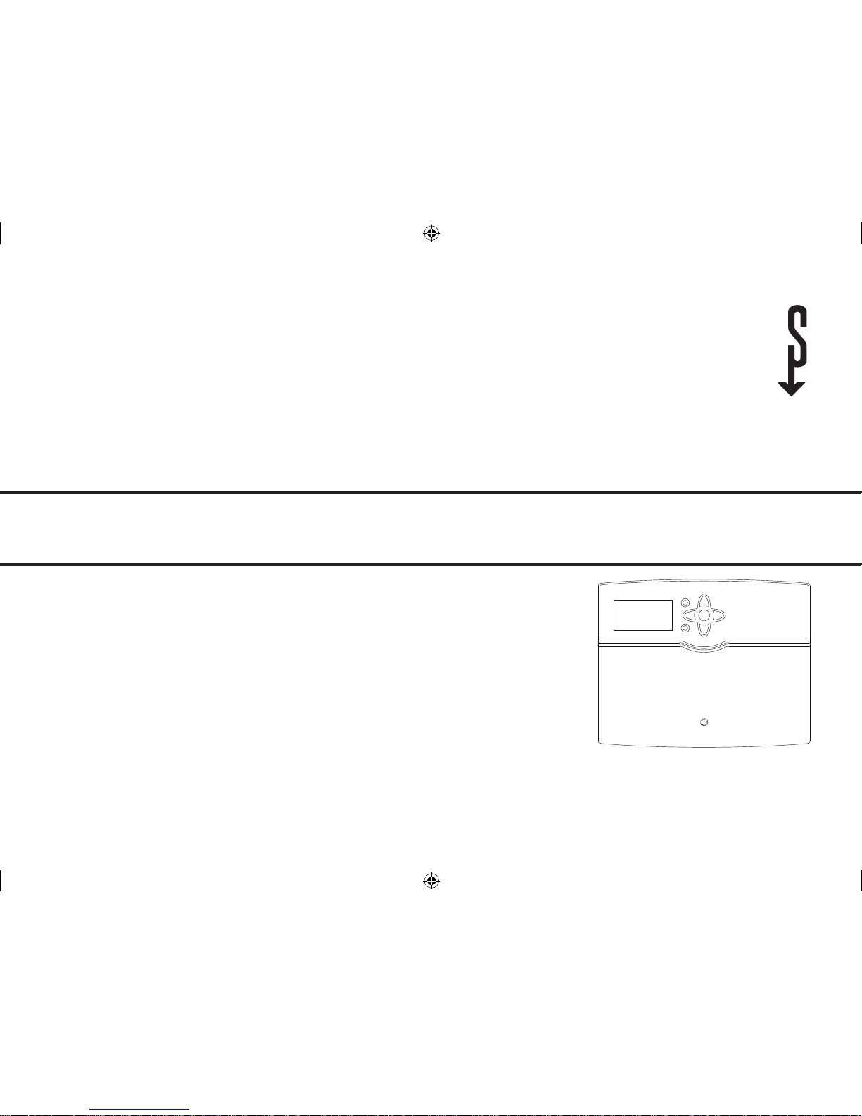
SOLAR CONTROLLER
» SOM 8 PLUS
295931-36390-8667 SOM 8 plus_en.indb 1 20.10.2011 13:14:19
2
Description of symbols
Signal words describe the danger that may occur,
when it is not avoided.
• WARNING means that injury, possibly life-threatening injury, can occur.
• ATTENTION means that damage to the appliance can occur.
Information about the product
Proper usage
The solar controller is designed for use in solar thermal systems and heating systems in compliance
with the technical data specied in this manual.
Improper use excludes all liability claims.
CE-Declaration of conformity
The product complies with the relevant directives and is therefore labelled with the
CE mark. The Declaration of Conformity is
available upon request, please contact us.
Note
Notes are indicated with an information
symbol.
Subject to technical change. Errors excepted.
Î Arrows indicate instruction steps that should be
carried out.
WARNING!
Warnings are indicated with a
warning triangle!
Î They contain information
on how to avoid the danger
described.
Note
Strong electromagnetic elds can impair
the function of the controller.
Î Make sure the controller as well as the
system are not exposed to strong electromagnetic elds.
Safety advice
Please pay attention to the following safety advice
in order to avoid danger and damage to people and
property.
Instructions
Attention must be paid to the valid local standards,
regulations and directives!
Target group
These instructions are exclusively addressed to authorised skilled personnel.
Only qualied electricians should carry out electrical
works.
Initial installation must be eected by qualied personnel named by the manufacturer.
Disposal
• Dispose of the packaging in an environmentally
sound manner.
• Dispose of old appliances in an environmentally sound manner. Upon request we will take
back your old appliances bought from us and
guarantee an environmentally sound disposal of
the devices.
Read this manual carefully to get the best performance from this unit.
Please keep this manual carefully.
295931-36390-8667 SOM 8 plus_en.indb 2 20.10.2011 13:14:20

3
Contents
1 Overview ........................................................4
1.1 Optional functions ......................................................5
2 Installation .....................................................5
2.1 Mounting .......................................................................5
2.2 Electrical connection .................................................6
2.3 Data communication / Bus ......................................7
2.4 SD card slot ....................................................................8
3 Step-by-step parameterisation ....................8
4 Operation and function ................................9
4.1 Buttons ............................................................................9
4.2 Selecting menu points and adjusting values ..9
4.3 Menu structure .........................................................11
5 Initial commissioning ................................. 12
5.1 Basic systems and hydraulic variants ................14
5.2 Overview of relay and sensor allocation..........15
6 Main menu .................................................. 30
7 Status ........................................................... 30
7.1 Solar .............................................................................. 30
7.2 Arrangement ............................................................. 30
7.3 Heating ........................................................................ 30
7.4 Messages ..................................................................... 30
7.5 Meas. / Balance values ............................................31
7.6 Service .......................................................................... 31
8 Solar ............................................................ 31
8.1 Basic solar settings...................................................31
8.2 Solar optional functions ........................................34
8.3 Solar expert menu ...................................................47
9 Arrangement .............................................. 47
9.1 Optional functions ................................................... 47
10 Heating ........................................................ 59
10.1 Demands ..................................................................... 60
10.2 Heating circuits ......................................................... 60
10.3 Optional functions ...................................................64
11 HQM ............................................................. 67
12 Basic settings .............................................. 69
13 SD card ........................................................ 69
14 Manual mode .............................................. 71
15 User code ..................................................... 72
16 In- / Outputs ................................................ 72
16.1 Modules ....................................................................... 72
16.2 Inputs ...........................................................................73
16.3 Outputs ........................................................................74
16.4 PWM-Proles..............................................................75
17 Troubleshooting ......................................... 76
18 Accessories .................................................. 80
18.1 Sensors and measuring instruments ................ 80
19 Index ............................................................ 81
295931-36390-8667 SOM 8 plus_en.indb 3 20.10.2011 13:14:20

4
1 Overview
• Extra large graphic display
• 14 relay outputs
• 12 temperature sensors
(system-dependent)
• 4 inputs for Grundfos Direct Sensors™
(2 × analog, 2 × digital)
• 4 PWM outputs for speed control of higheciency pumps
• Datalogging / rmware updates via SD memory card
• 2 internal, weather-compensated heating
circuits
• Pre-programmed optional functions
• Drainback option
• Time-controlled thermostat function
• Heating period thermal disinfection
• VBus
®
• Energy-saving switch-mode power supply
Included:
1 x solar control unit
1 x accessory bag
3 x screw and wall plug
13 x strain relief and screw
Additionally enclosed in the full kit:
2 x FKP6 temperature sensor
4 x FRP6 temperature sensor
Technical data
SOM 8 plus
230933
Height mm 200
Width mm 253
Depth mm 43
IP-Rating IP20
Rated voltage V 100...240
Phases 1/N/PE
Frequency Hz 50...60
Total switching current A 6,3
Power consumption W < 1
Relay capacity A 1 (1)
Number of inputs 15
Number of switched outputs 14
Casing material
Plastic,
PC-ABS/PMMA
Ambient temperature °C 0...40
Note
The SD card is not included with the controller. For more information about accessories, see page 69
254
205
47
295931-36390-8667 SOM 8 plus_en.indb 4 20.10.2011 13:14:20
5
2 Installation
2.1 Mounting
The unit must only be located in dry interior rooms.
The controller must additionally be supplied from a
double pole switch with contact gap of at least 3 mm
[0.12"].
Please pay attention to separate routing of sensor
cables and mains cables.
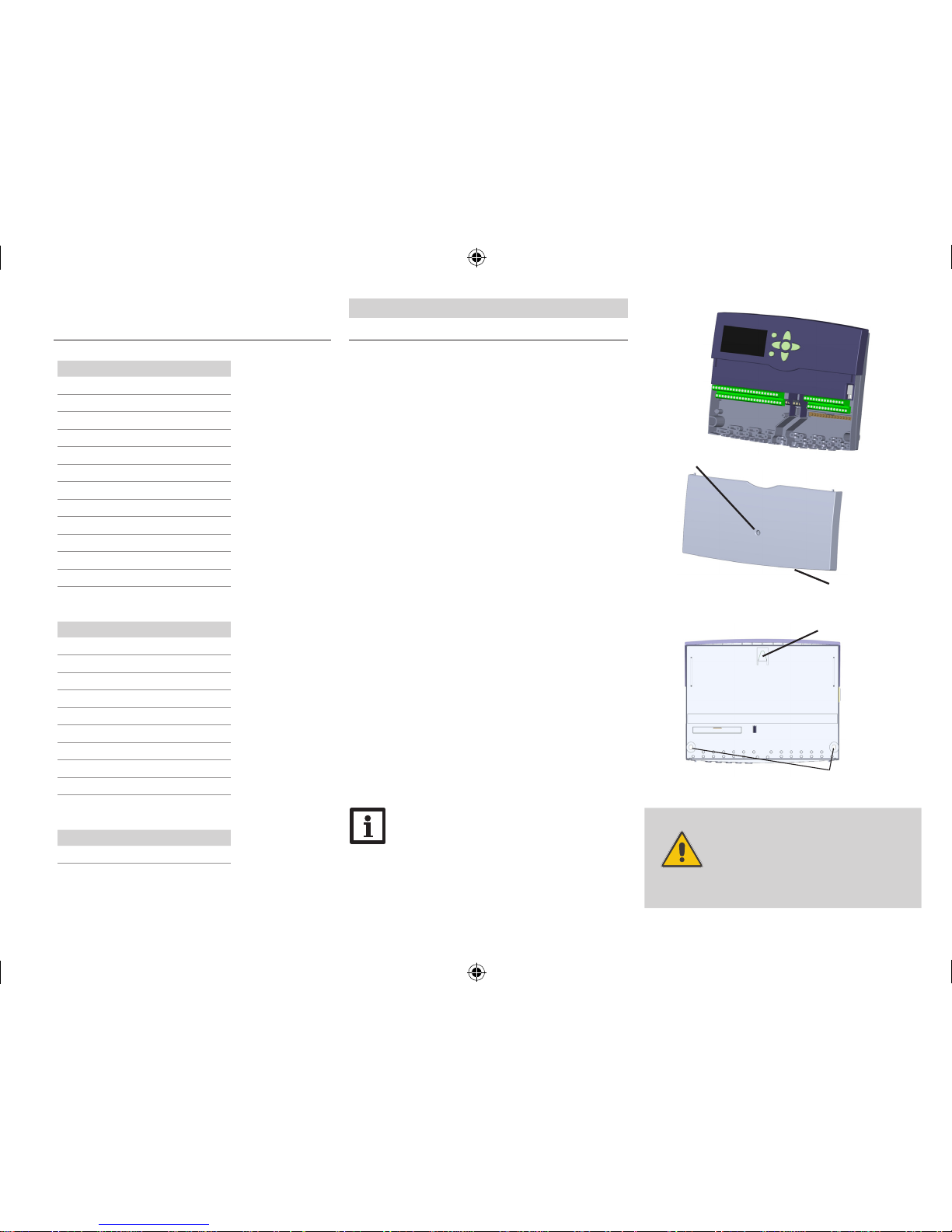
In order to mount the device to the wall, carry out
the following steps:
Î Unscrew the cross-head screw from the cover
and remove it along with the cover from the
housing
Î Mark the upper fastening point on the wall. Drill
and fasten the enclosed wall plug and screw leaving the head protruding
Î Hang the housing from the upper fastening
point and mark the lower fastening points (cen-
tres 223 mm [8.8"])
Î Insert lower wall plugs
Î Fasten the housing to the wall with the lower
fastening screws and tighten
Î Carry out the electrical wiring in accordance
with the terminal allocation, see chap. 2.2
Î Put the cover on the housing
Î Attach with the fastening screw
1.1 Optional functions
Solar
Bypass
CS Bypass
External heat exchanger
Tube collector
Target temperature
Antifreeze
Afterheating suppression
Parallel relay
Cooling mode
Drainback
Twin pump
Heat dump
Flow rate monitoring
Arrangement
Parallel relay
Mixer
Boiler loading
Error relay
Heat exchange
Solid fuel boiler
Circulation
Return preheating
Function block
Irradiation switch
Heating
Thermal Disinfection
DHW heating
WARNING!
Electric shock!
Upon opening the housing, live
parts are exposed.
Î Always disconnect the
controller from power supply
before opening the housing!
cover
screw
Note
Strong electromagnetic elds can impair
the function of the controller.
Make sure the controller as well as the system are not exposed to strong electromagnetic elds.
upper fastening point
lower fastening point
295931-36390-8667 SOM 8 plus_en.indb 5 20.10.2011 13:14:20
6
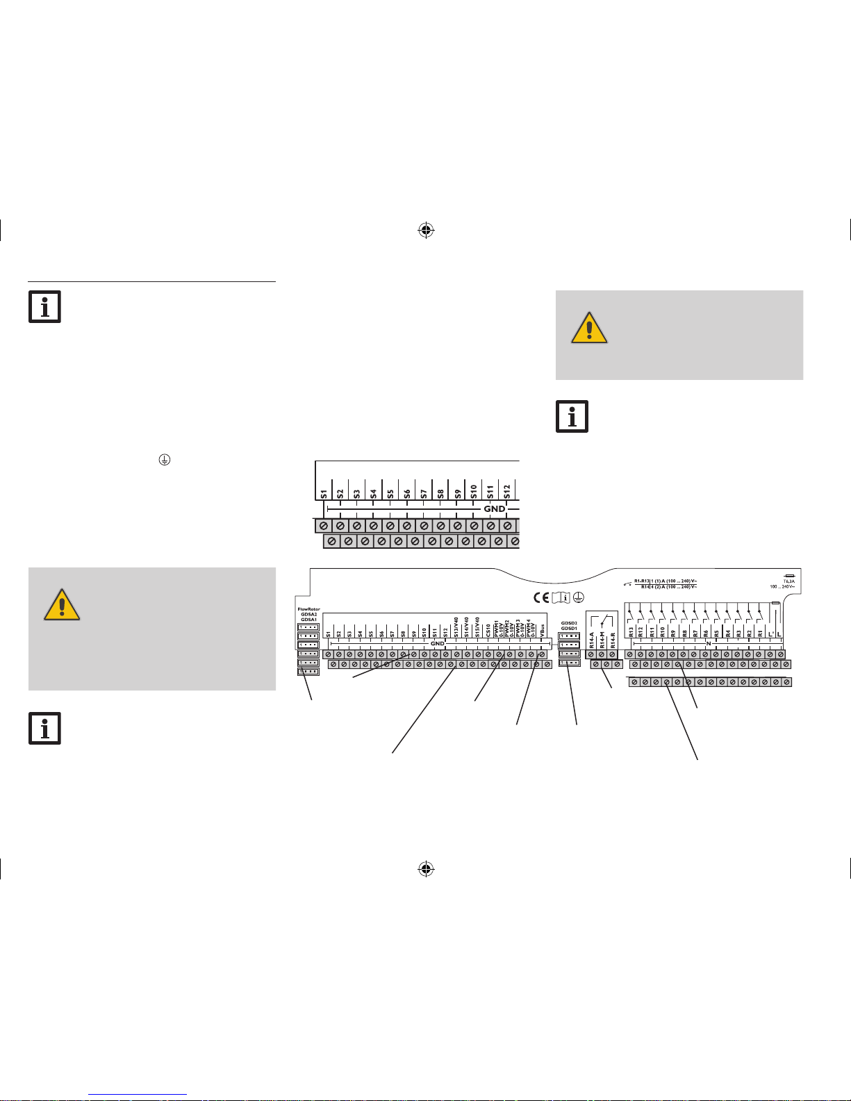
2.2 Electrical connection
WARNING!
ESD damage!
Electrostatic discharge can lead to
damage to electronic components!
Î Take care to discharge
properly before touching the
inside of the device! To do
so, touch a grounded surface
such as a radiator or tap!
Note:
The pump speed must be set to 100 %
when auxiliary relays or valves are connected.
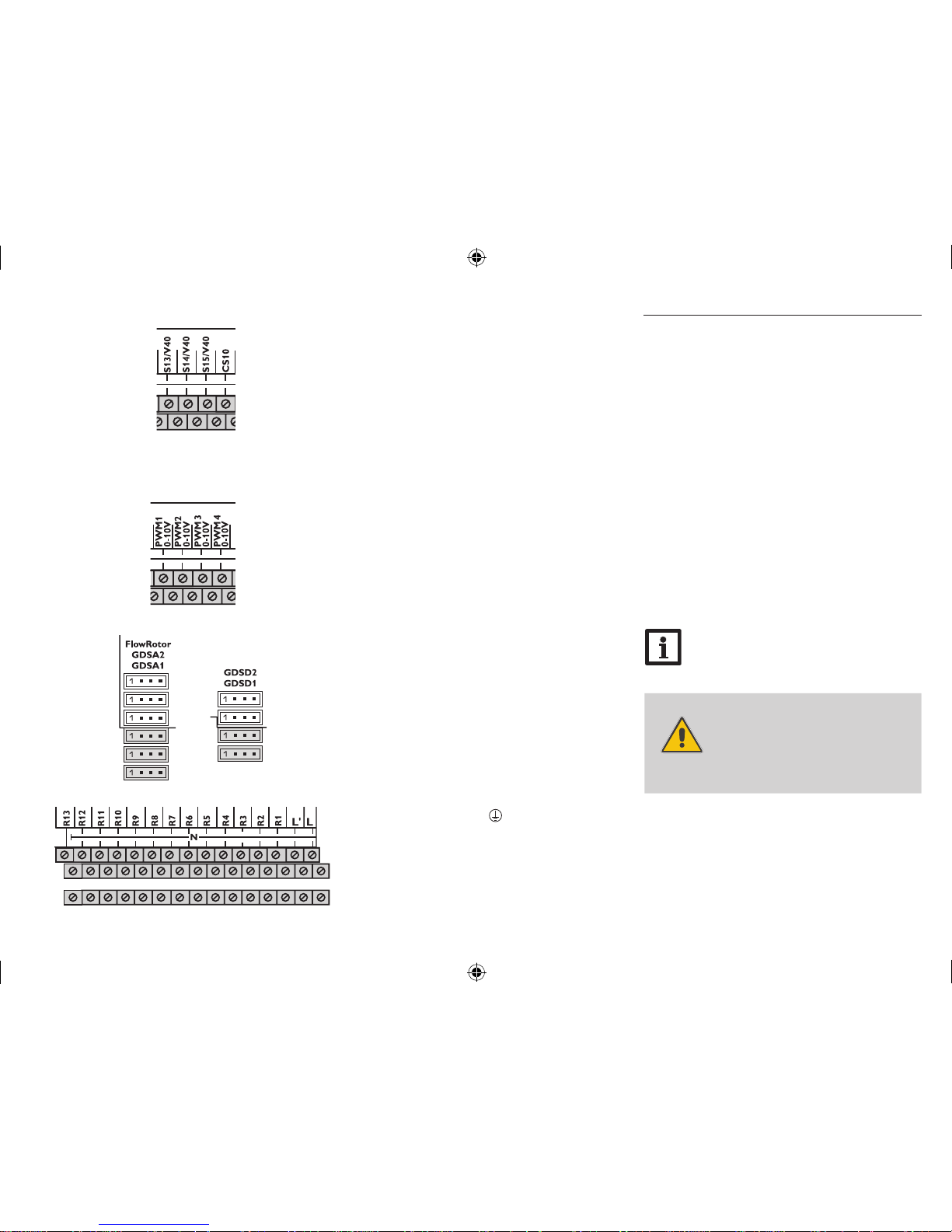
input for analog
Grundfos Direct
Sensors™
input for digital
Grundfos Direct Sensors™
potential-free
changeover relay
sensor
ground common terminal block
sensor terminals
protective earth
conductor common
terminal block (PE)
neutral conductor
common terminal
block
Note
For more details about the initial commissioning procedure, see page 12.
Note
Connecting the device to the power supply
must always be the last step of the installation!
The controller is equipped with 14 relays in total to
which loads such as pumps, valves, etc. can be connected:
Relays 1 ... 13 are semiconductor relays, designed for
pump speed control:
Conductor R1 ... R13
Neutral conductor N (common terminal block)
Protective earth conductor
(common terminal
block)
Relay 14 is a potential-free changeover relay:
R14-A = normally open contact
R14-M = centre contact
R14-R = normally closed contact
WARNING!
Electric shock!
Upon opening the housing, live
parts are exposed.
Î Always disconnect the
controller from power supply
before opening the housing!
Depending on the product version, mains cables
and sensor cables are already connected to the device. If that is not the case, please proceed as follows:
Temperature sensors have to be connected to the
terminals S1 ... S12 and GND (either polarity).
PWM (0-10 V)
terminals
VBus
®
295931-36390-8667 SOM 8 plus_en.indb 6 20.10.2011 13:14:20
7
2.3 Data communication / Bus
The controller is equipped with the VBus
®
for data
transfer with and energy supply to external modules. The connection is carried out at the two terminals marked VBus and GND (any polarity).
The terminals S13 to S15 can be used as impulse inputs for V40 owmeters or as inputs for FS08 ow
switches.
V40 owmeters can be connected to the terminals
S13 / V40 to S15 / V40 and GND (either polarity).
Connect the irradiation sensor CS10 to the terminals CS10 and GND with correct polarity. To do so,
connect the cable marked GND to the GND common
terminal block, the cable marked CS to the terminal
marked CS10.
The terminals marked PWM are control outputs for
high-eciency pumps.
In the In-/Outputs menu, relays can be allocated to
the PWM outputs.
Connect the FlowRotor to the input marked FlowRotor.
Connect the analog Grundfos Direct Sensors™ to
the inputs GDSA1 and GDSA2.
Connect the digital Grundfos Direct Sensors™ to
the GDSD1 and GDSD2 inputs.
The controller is supplied with power via a mains
cable. The power supply of the device must be
100...240V~ (50...60Hz).
The mains connection is at the terminals:
Neutral conductor N
Conductor L
Conductor L' (L' is not connected with the mains
cable. L' is a fused contact permanently carrying
voltage)
Protectiv earth conductor
(common terminal
block)
Note:
For more information about accessories,
see page 80.
WARNING!
Electric shock!
L‘ is a fused contact permanently
carrying voltage
Î Always disconnect the
controller from power supply
before opening the housing!
295931-36390-8667 SOM 8 plus_en.indb 7 20.10.2011 13:14:21

8
2.4 SD card slot
The controller is equipped
with an SD card slot.
With an SD card, the following
functions can be carried out:
• Store measurement and
balance values onto the SD
card. After the transfer to a
computer, the values can
be opened and visualised, e. g. in a spreadsheet
programme.
• Prepare adjustments and parameterisations on a
computer and transfer them via the SD card.
• Store adjustments and parameterisations on the
SD card and, if necessary, retrieve them from
there.
A standard SD card is not included.
For more information about using an SD card, see
page 69.
3 Step-by-step parameterisation
The SOM 8 plus is a controller that oers a broad
variety of functions to the user. At the same time,
the user has a lot of freedom in congurating them.
Therefore, to set up a complex system, careful planning is required. We recommend drawing a sketch of
the system rst.
If planning, hydraulic execution and electrical connection have all been carried out successfully, proceed as follows:
1. Runningthecommissioningmenu
The commissioning menu is run after the rst connection and after every reset. It will request the following basic adjustments:
• Menu language
• Temperature unit
• Volume unit
• Pressure unit
• Energy unit
• Time
• Date
• Solar system
• Hydraulic variant
At the end of the commissioning menu, a safety en-
quiry follows. If the safety enquiry is conrmed, the
adjustments are saved.
For further information about the commissioning
menu see page 12.
2. Registeringsensors
If owmeters, ow switches, Grundfos Direct Sensors™ and/or external extension modules are connected, these have to be registered in the In-/Outputs menu.
For further information about the registration of modules and sensors see page 72.
3. Activatingsolaroptionalfunctions
The basic solar system has been adjusted during
commissioning. Now, optional functions can be selected, activated and adjusted.
Free relays can be allocated to optional functions
which require a relay. The controller always suggests
the numerically smallest free relay.
Sensors can be allocated to more than one function.
For further information about the solar optional
functions see page 34.
4. Activatingoptionalarrangementfunctions
Now, optional functions for the non-solar part of the
arrangement can be selected, activated and adjusted.
Free relays can be allocated to optional functions
which require a relay. The controller always suggests
the numerically smallest free relay.
Sensors can be allocated any number of times without impairing any other functions.
For further information about the optional arrangement functions see page 47.
5. Adjustingheatingcircuitsandactivatingoptionalheatingfunctions
Now, heating circuits can be activated and adjusted.
Internal heating circuits are only oered as long as at
least 3 relays are free.
For the heating part of the arrangement, optional
functions can be selected, activated and adjusted.
To heating circuits and optional functions which require one or more relays, the corresponding number
of free relays can be allocated. The controller always
suggests the numerically smallest free relay.
Sensors can be allocated any number of times without impairing any other functions.
For further information about heating circuits and
optional heating functions see page 59.
295931-36390-8667 SOM 8 plus_en.indb 8 20.10.2011 13:14:22
9
4 Operation and function
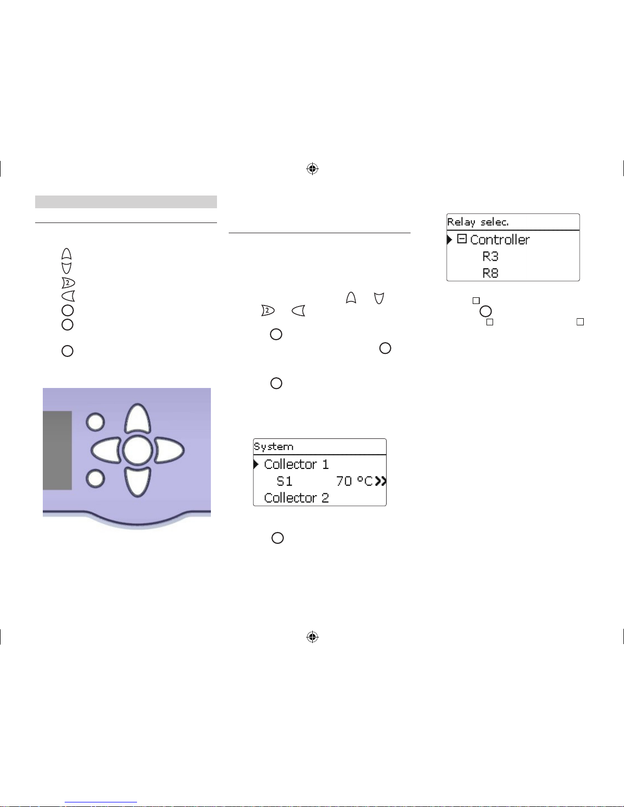
4.1 Buttons
The controller is energised via the 7 buttons next to
the display.They have the following functions:
Button
1
- scrolling upwards
Button
3
- scrolling downwards
Button
- increasing adjustment values
Button
4
- reducing adjustment values
Button
5
- conrming
Button
6
- entering the status menu / chimney
sweeper mode (system-dependent)
Button
7
- escape button for changing into the
previous menu
1
2
4
6
3
5
7
4.2 Selecting menu points and adjusting
values
During normal operation of the controller, the display is in the main menu. If no button is pressed for a
few seconds, the display illumination goes out.
Press any key to reactivate the display illumination.
Î In order to scroll through a menu or to adjust
a value, press either buttons
1
and 3 or but-
tons and
4
Î To open a submenu or to conrm a value, press
button 5
Î To enter the status menu, press button
6
– un-
conrmed adjustments will not be saved
Î To switch one menu level upwards press
button
7
– unconrmed adjustments will not
be saved
If no button has been pressed within a couple of minutes, the adjustment is cancelled and the previous
value is retained.
If the symbol
» is shown behind a menu item, pres-
sing button 5 will open a new submenu.
If the symbol + is shown in front of a menu item,
pressing button 5 will open a new submenu. If it is
already opened, a – is shown instead of the +.
295931-36390-8667 SOM 8 plus_en.indb 9 20.10.2011 13:14:22
10
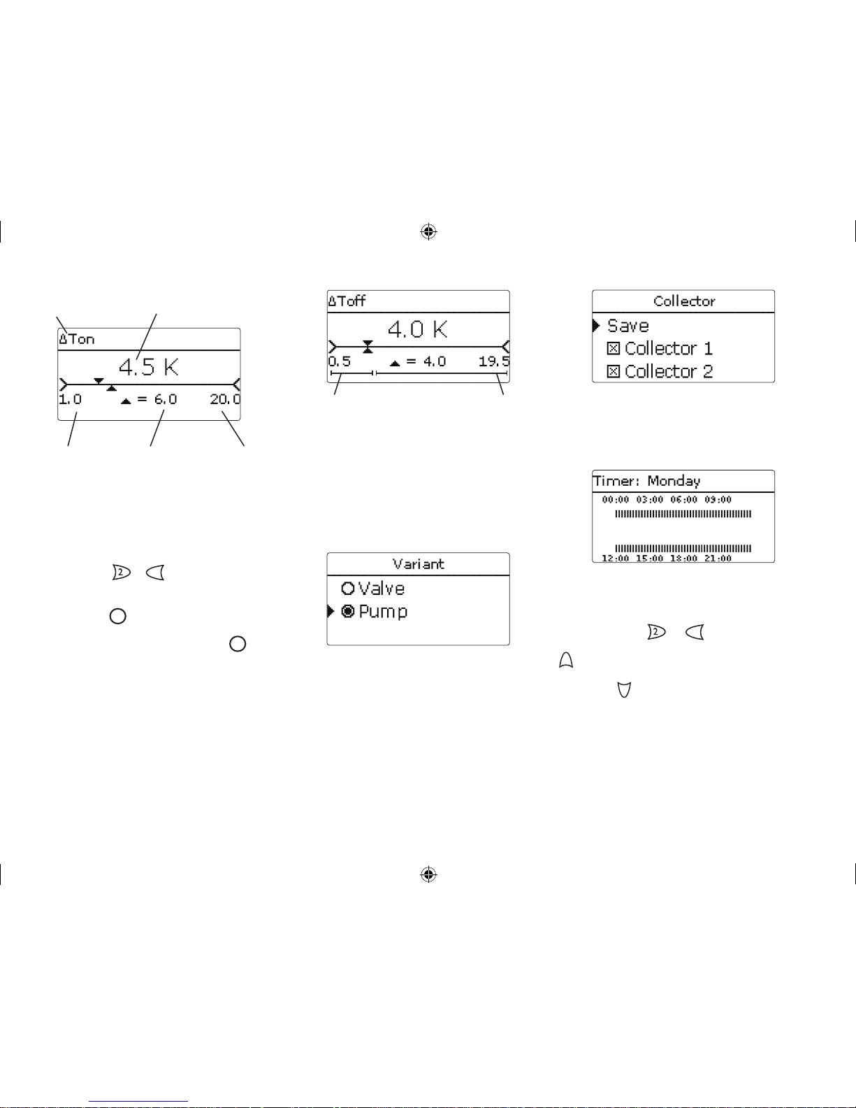
Values and adjustments can be changed in dierent
ways:
Numeric values can be adjusted by means of a slide
bar. The minimum value is indicated to the left, the
maximum value to the right. The large number above the slide bar indicates the current adjustment. By
pressing buttons
or 4 the upper slide bar can
be moved to the left or to the right.
Only after the adjustment has been conrmed by
pressing button
5
will the number below the slide bar indicate the new value. The new value will be
saved if it is conrmed by pressing button 5 again.
current value savedminimum value maximum value
adjusted value
(not yet conrmed)
adjustment channel
When two values are locked against each other, they
will display a reduced adjustment range depending
on the adjustment of the respective other value.
In this case, the active area of the slide bar is shortened, the inactive area is indicated as a dotted line.
The indication of the minimum and maximum values will adapt to the reduction.
active area inactive area
If only one item of several can be selected, they will
be indicated with "radio buttons". When one item
has been selected, the radio button in front of it is
lled.
If more than one item of several can be selected, they
will be indicated with checkboxes. When an item has
been selected, an x appears inside the checkbox.
The time frames for the timer can be adjusted in
steps of 15 minutes on a time line.
The cursor can be moved along the time line by
pressing buttons
or 4. The beginning of a
time frame can be determined by pressing button
1
.
The end of a time frame can be determined by pressing button
3
.
295931-36390-8667 SOM 8 plus_en.indb 10 20.10.2011 13:14:24
11
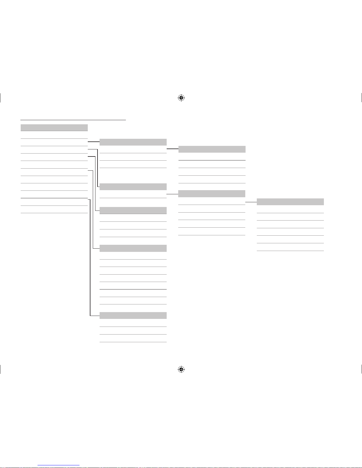
4.3 Menu structure
Main menu
Status
Solar
Arrangement
Heating
HQM
Basic settings
SD card
Manual mode
User code
In- / Outputs
Expert
Solar
Basic settings
Optional functions
Expert
Arrangement
Optional functions
Basic settings
System
Collector
Store
Loading logic
Optional functions
Parallel relay
Mixer
Store loading
Error relay
...
Heating
Demands
Heating circuits
Optional functions
Parallel relay
Relay
Reference relay
Overrun
Delay
Inverted
...
The menu items and adjustment values selectable are variable depending on adjustments
already made. The gure only shows an exemplary excerpt of the complete menu in order to
visualise the menu structure.
Basic settings
Language
Auto DST
Date
Time
Temp. unit
Vol. unit
...
In- / Outputs
Modules
Inputs
Outputs
295931-36390-8667 SOM 8 plus_en.indb 11 20.10.2011 13:14:24
12
5 Initial commissioning
When the hydraulic system is lled and ready for
operation, connect the controller to the mains.
The controller runs an initialisation phase in which
the directional pad ashes red.
When the controller is commissioned for the rst
time or when it is reset, it will run a commissioning
menu after the initialisation phase. The commissioning menu leads the user through the most important adjustment channels needed for operating the
system.
Commissioning menu
The commissioning menu consists of the channels
described in the following. In order to make an adjustment, push button
5
. Adjust the value by pressing buttons 4 and 2, then bush button 5 to
conrm. The next channel will appear on the display.
5
5
adjustment mode
button navigation
changing a value
conrming a value
next parameter appears auto-
matically
2
4
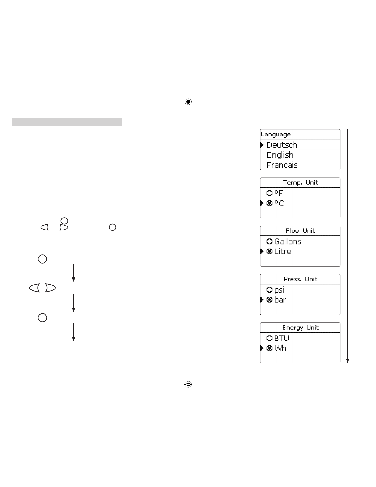
1. Language:
Î Adjust the desired menu language.
2. Units:
Î Adjust the desired temperature unit.
Î Adjust the desired volume unit.
Î Adjust the desired pressure unit.
Î Adjust the desired energy unit.
295931-36390-8667 SOM 8 plus_en.indb 12 20.10.2011 13:14:25
13
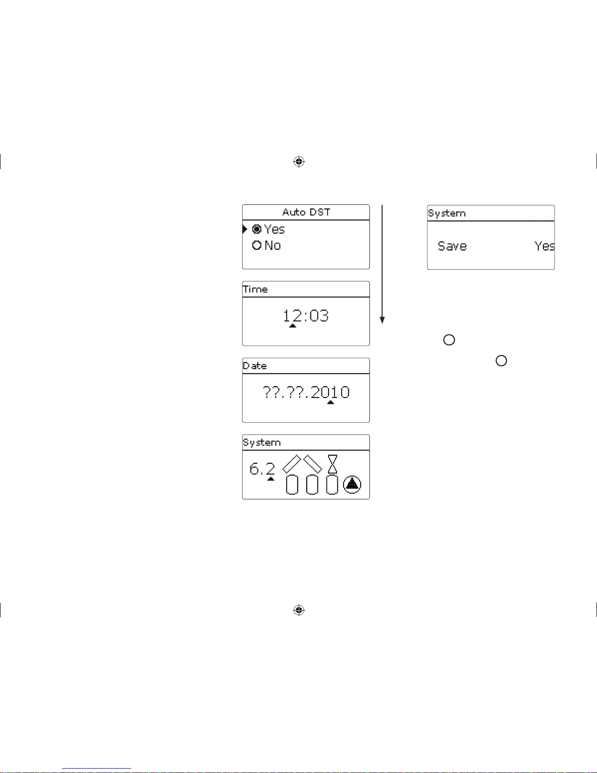
4. Time:
Î Adjust the clock time. First of all adjust the
hours, then the minutes.
5. Date:
Î Adjust the date. First of all adjust the year, then
the month and then the day.
3. Daylightsavingstimeadjustment:
Î Activate or deactivate the automatical daylight
savings time adjustment.
7. Completingthecommissioningmenu:
After the system has been selected, a security enquiry appears. If the enquiry is conrmed, the adjustments will be saved.
Î In order to conrm the security enquiry, press
button
5
.
Î In order to reenter the commissioning menu
channels, press button
7
.
If the security enquiry has been conrmed, the controller is ready for operation and should enable an
optimum system operation.
All adjustments made during commissioning can, if
necessary, be changed later on in the basic settings
menu.
6. Selectionofthesolarsystem:
Î Adjust the desired solar system (number of coll-
ectors and stores, hydraulic variants).
295931-36390-8667 SOM 8 plus_en.indb 13 20.10.2011 13:14:26
14
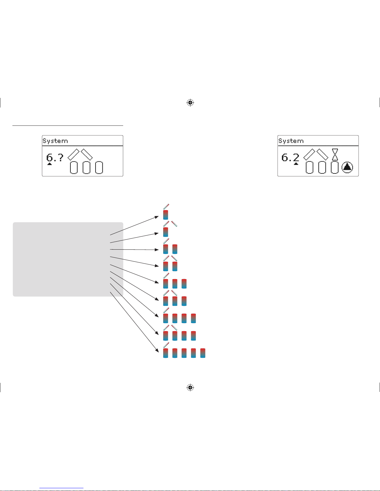
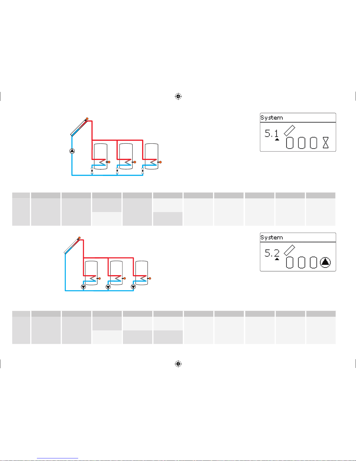
5.1 Basic systems and hydraulic variants
The controller is preprogrammed for 9 basic systems.
The selection depends on the number of heat sources (collector elds) and heat sinks (stores, pool).
Factory setting is system 1.
A solar system with store loading in layers is implemented as a 2-store system
(store top = store 1; store bottom = store 2).
The selection of the basic solar system is one of the
most important adjustments and is thus requested
already in the commissioning menu.
First, the basic system is adjusted by means of the
number of stores and collectors elds, then the hydraulic variant.
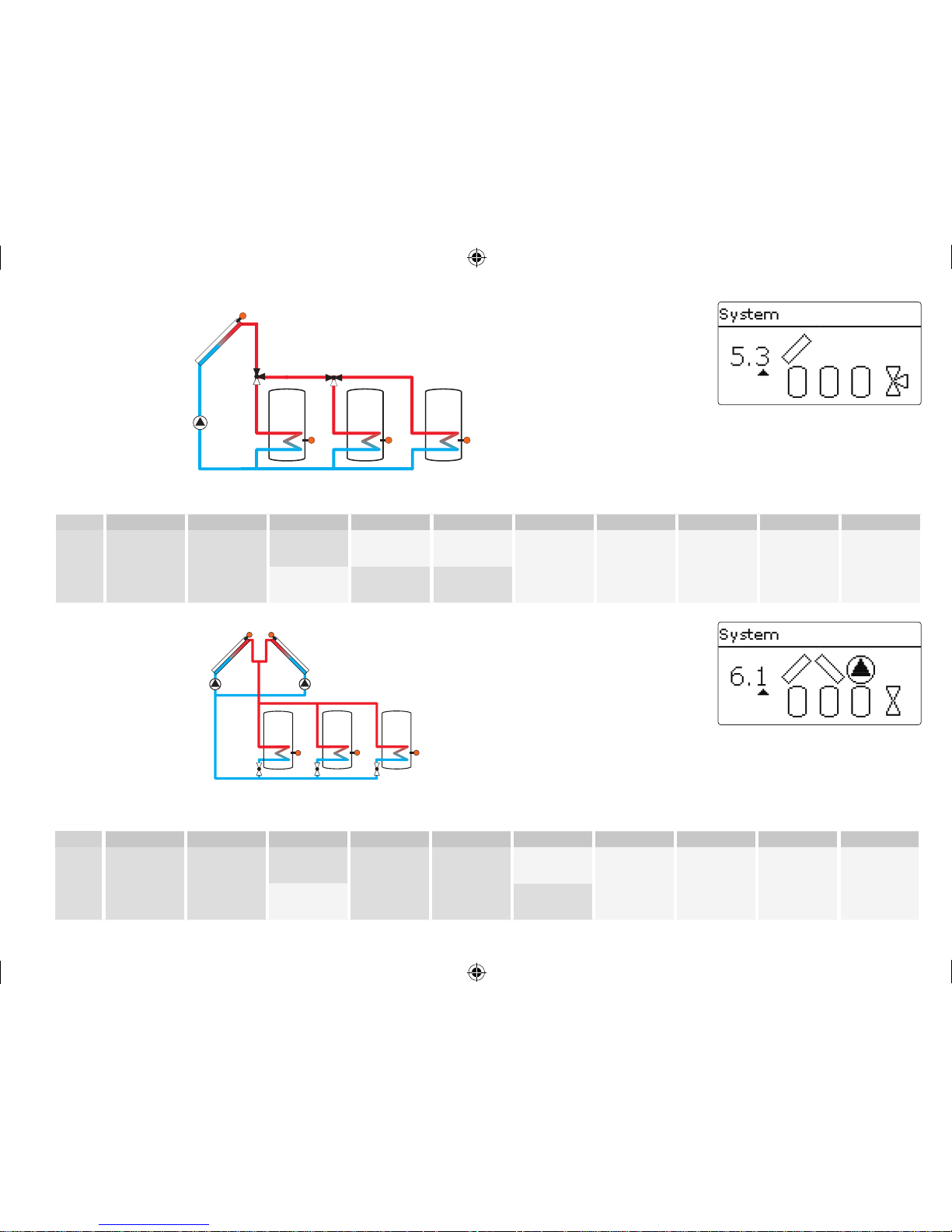
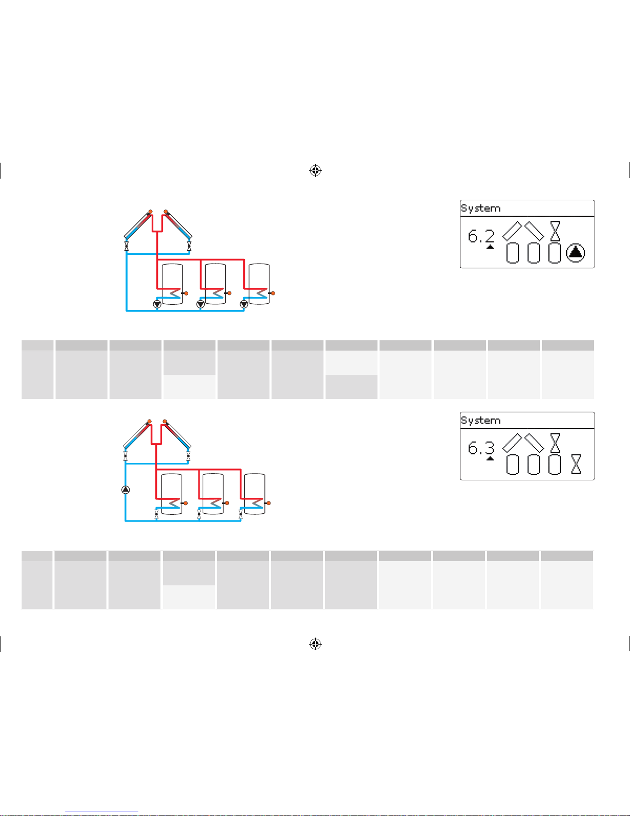
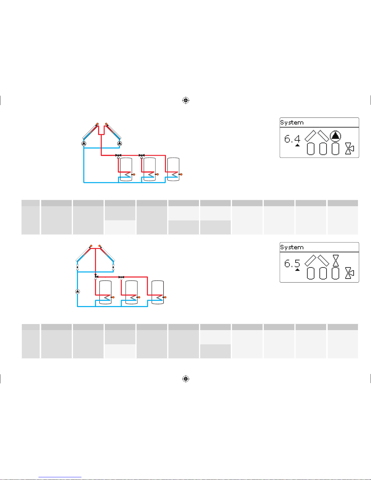
The selected system is visualised by the corresponding number of store and collector symbols. The gure to the left shows system 6 which consists of 3
stores and 2 collector elds ("east- / west collectors").
System 0: no solar system
System 1: 1 collector eld - 1 store
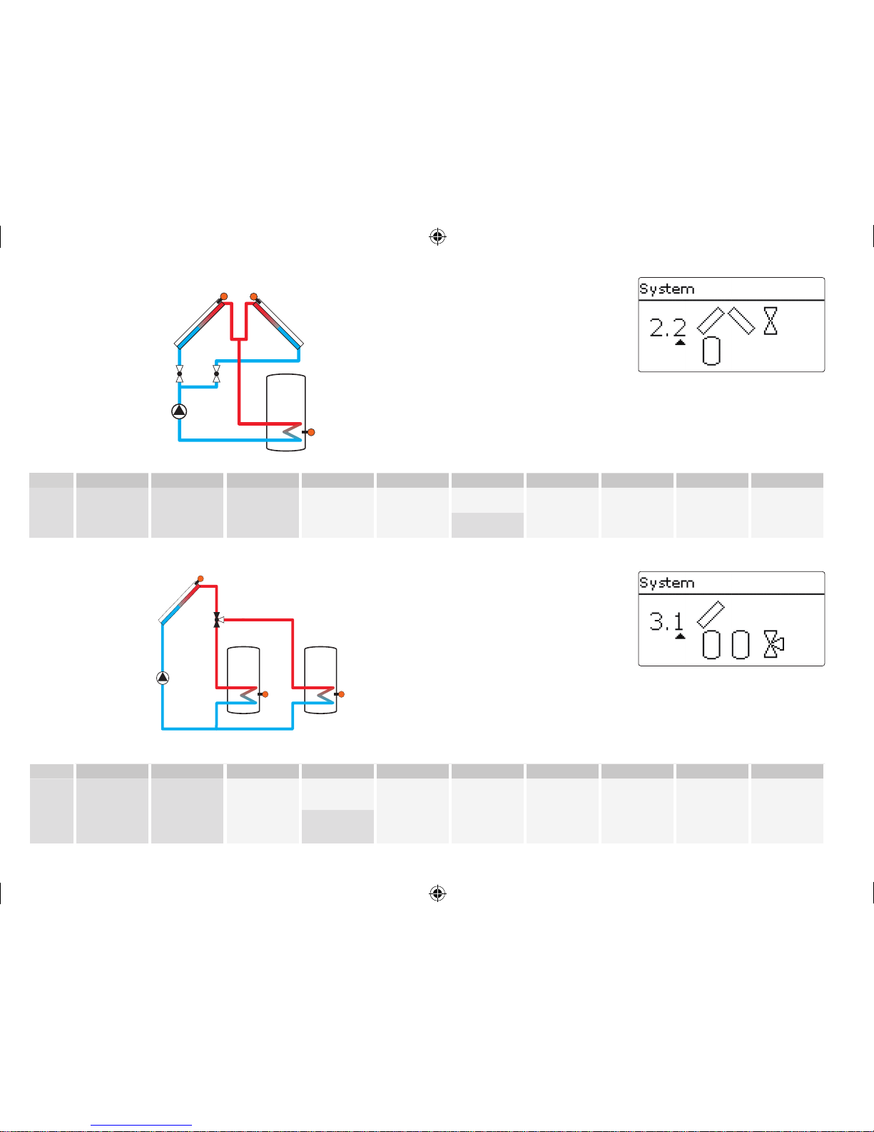
System 2: east- / west collectors - 1 store
System 3: 1 collector eld - 2 stores
System 4: east- / west collectors - 2 stores
System 5: 1 collector eld - 3 stores
System 6: east- / west collectors - 3 stores
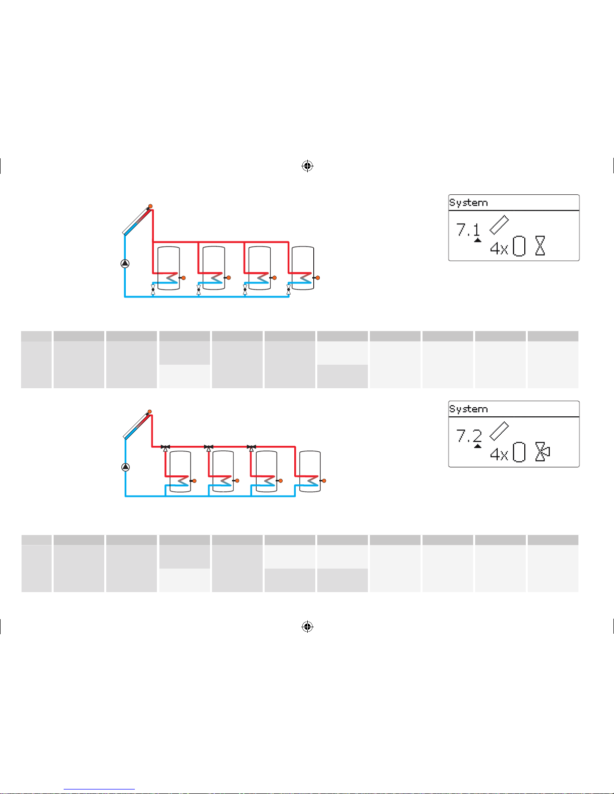
System 7: 1 collector eld - 4 stores
System 8: east- / west collectors - 4 stores
System 9: 1 collector eld - 5 stores
System
Variant
The hydraulic variant refers to the dierent actuators
that are to be controlled. They are visualised on the
display by means of symbols, when the variant is
selected. The upper symbol indicates the actuator
belonging to the collector elds, the lower one the
actuators belonging to the stores.
The exemplary gure shows the display indicated
when system 6, variant 2 has been selected. In this
case, each collector eld has a 2-port valve, the
stores are loaded by means of pump logic.
For each variant, the controller allocates the corresponding relays and sensors. The allocations of the
most important combinations are shown in 5.2.
295931-36390-8667 SOM 8 plus_en.indb 14 20.10.2011 13:14:26
15
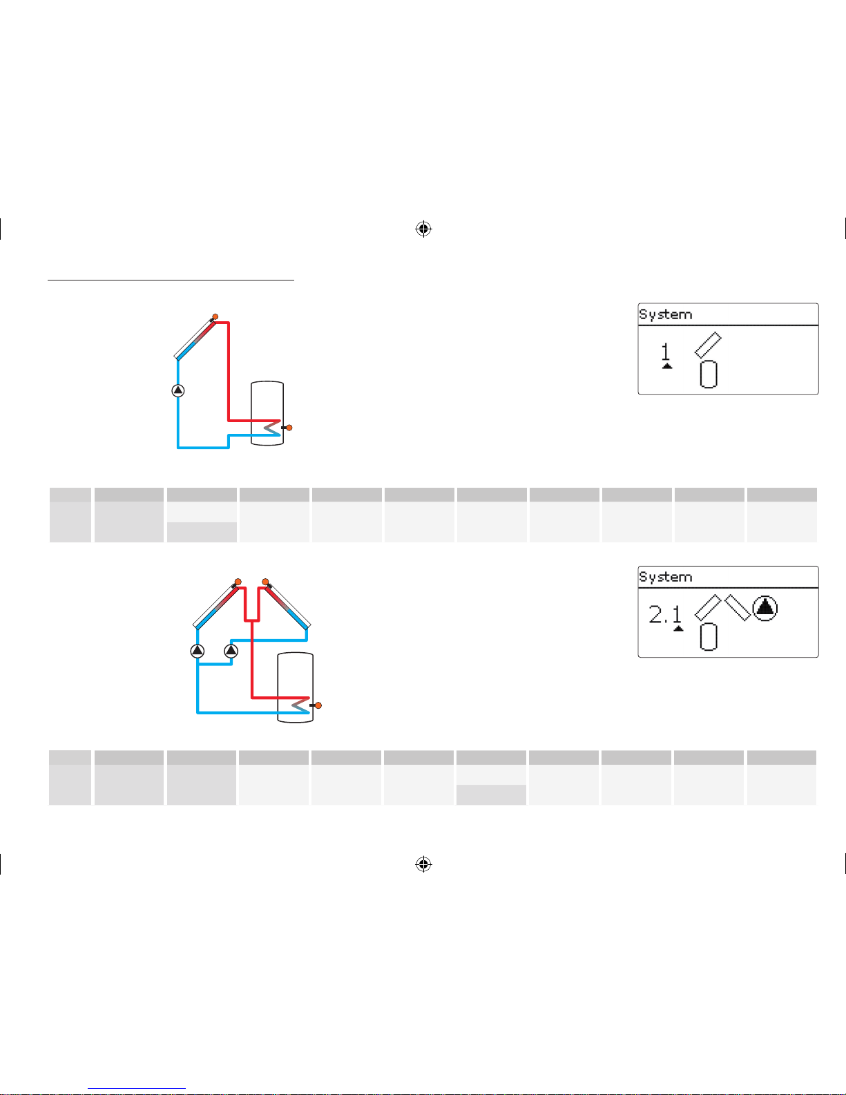
5.2 Overview of relay and sensor allocation
System 1
R1
S1
S2
Relay / sensor allocation
1 2 3 4 5 6 7 8 9 10-14
Relay Solar pump Opt. function Opt. function Opt. function Opt. function Opt. function Opt. function Opt. function Opt. function Opt. function
Sensor Collector 1 Store base Free Free Free Free Free Free Free Free
System 2 variant 1
S1 S6
R1 R2
S2
Relay / sensor allocation
1 2 3 4 5 6 7 8 9 10-14
Relay Pump coll. 1 Pump coll. 2 Opt. function Opt. function Opt. function Opt. function Opt. function Opt. function Opt. function Opt. function
Sensor Collector 1 Store base Free Free Free Collector 2 Free Free Free Free
295931-36390-8667 SOM 8 plus_en.indb 15 20.10.2011 13:14:27
16
S1 S6
R1 R2
S2
R3
System 2 variant 2
Relay / sensor allocation
1 2 3 4 5 6 7 8 9 10-14
Relay 2PV coll. 1 2PV coll. 2 Solar pump Opt. function Opt. function Opt. function Opt. function Opt. function Opt. function Opt. function
Sensor Collector 1 Store base Free Free Free Collector 2 Free Free Free Free
System 3 variant 1
S1
R2
R1
S2
S4
Relay / sensor allocation
1 2 3 4 5 6 7 8 9 10-14
Relay Solar pump
3PV
store 2
Optional
function
Optional
function
Optional
function
Optional
function
Optional
function
Optional
function
Optional
function
Optional
function
Sensor
Collector Store 1 base Free Store 2 base Free Free Free Free Free Free
295931-36390-8667 SOM 8 plus_en.indb 16 20.10.2011 13:14:27
17
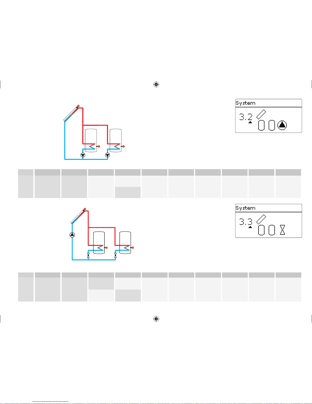
System 3 variant 2
S1
R1 R2
S4S2
Relay / sensor allocation
1 2 3 4 5 6 7 8 9 10-14
Relay
Solar pump
store 1
Solar pump
store 2
Optional
function
Optional
function
Optional
function
Optional
function
Optional
function
Optional
function
Optional
function
Optional
function
Sensor Collector Store 1 base Free Store 2 base Free Free Free Free Free Free
System 3 variant 3
R1
R2 R3
S2 S4
S1
Relay / sensor allocation
1 2 3 4 5 6 7 8 9 10-14
Relay Solar pump
2PV
store 1
2PV
store 2
Optional
function
Optional
function
Optional
function
Optional
function
Optional
function
Optional
function
Optional
function
Sensor Collector Store 1 base Free Store 2 base Free Free Free Free Free Free
295931-36390-8667 SOM 8 plus_en.indb 17 20.10.2011 13:14:27
18
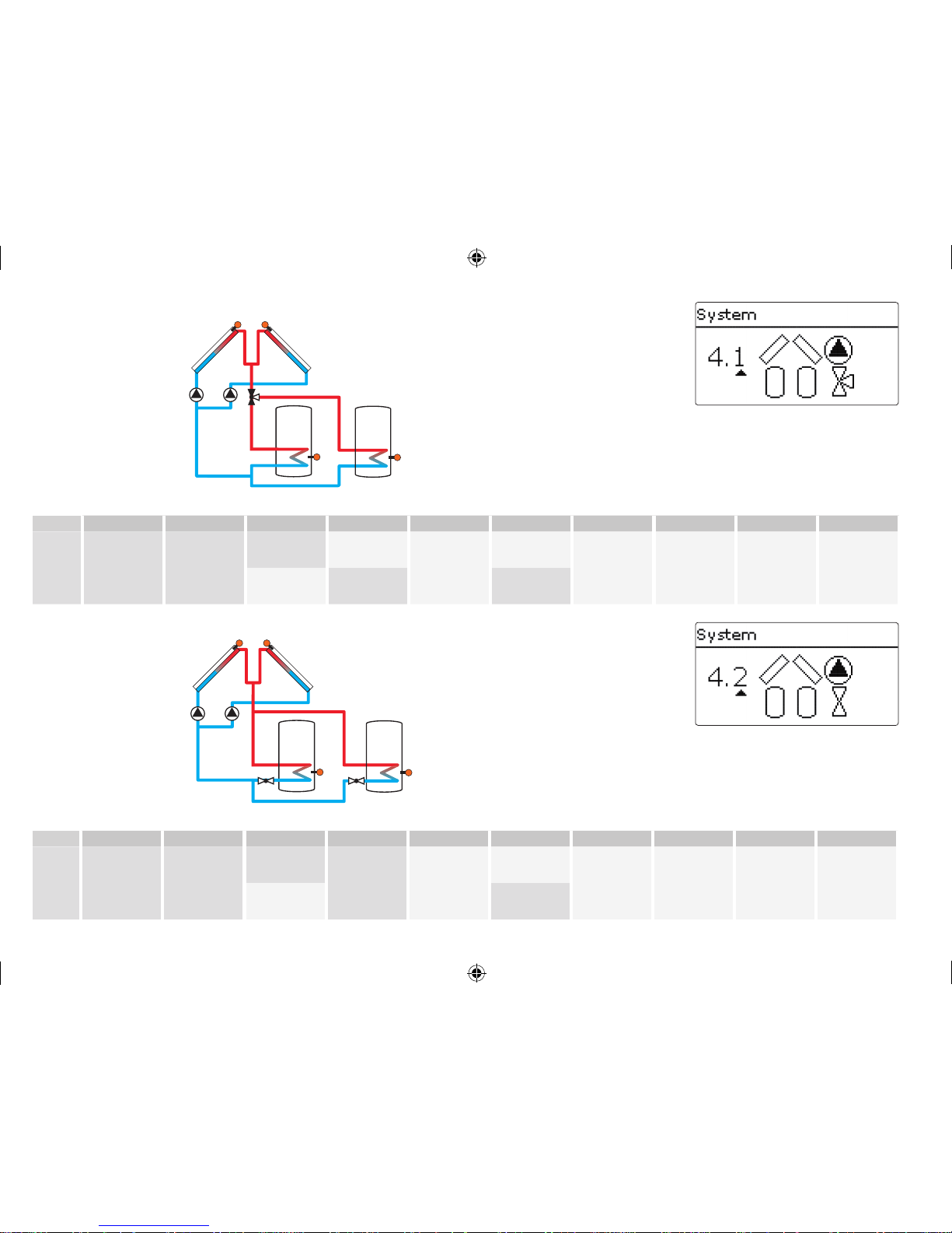
System 4 variant 1
R1
R2
R3
S2 S4
S1 S6
Relay / sensor allocation
1 2 3 4 5 6 7 8 9 10-14
Relay
Pump coll. 1 Pump coll. 2
3PV
store 2
Optional
function
Optional
function
Optional
function
Optional
function
Optional
function
Optional
function
Optional
function
Sensor
Collector 1 Store 1 base Free Store 2 base Free Collector 2 Free Free Free Free
System 4 variant 2
R1
R2
S1 S6
R3 R4
S4S2
Relay / sensor allocation
1 2 3 4 5 6 7 8 9 10-14
Relay
Pump coll. 1 Pump coll. 2
2PV
store 1
2PV
store 2
Optional
function
Optional
function
Optional
function
Optional
function
Optional
function
Optional
function
Sensor
Collector 1 Store 1 base Free Store 2 base Free Collector 2 Free Free Free Free
295931-36390-8667 SOM 8 plus_en.indb 18 20.10.2011 13:14:28
19
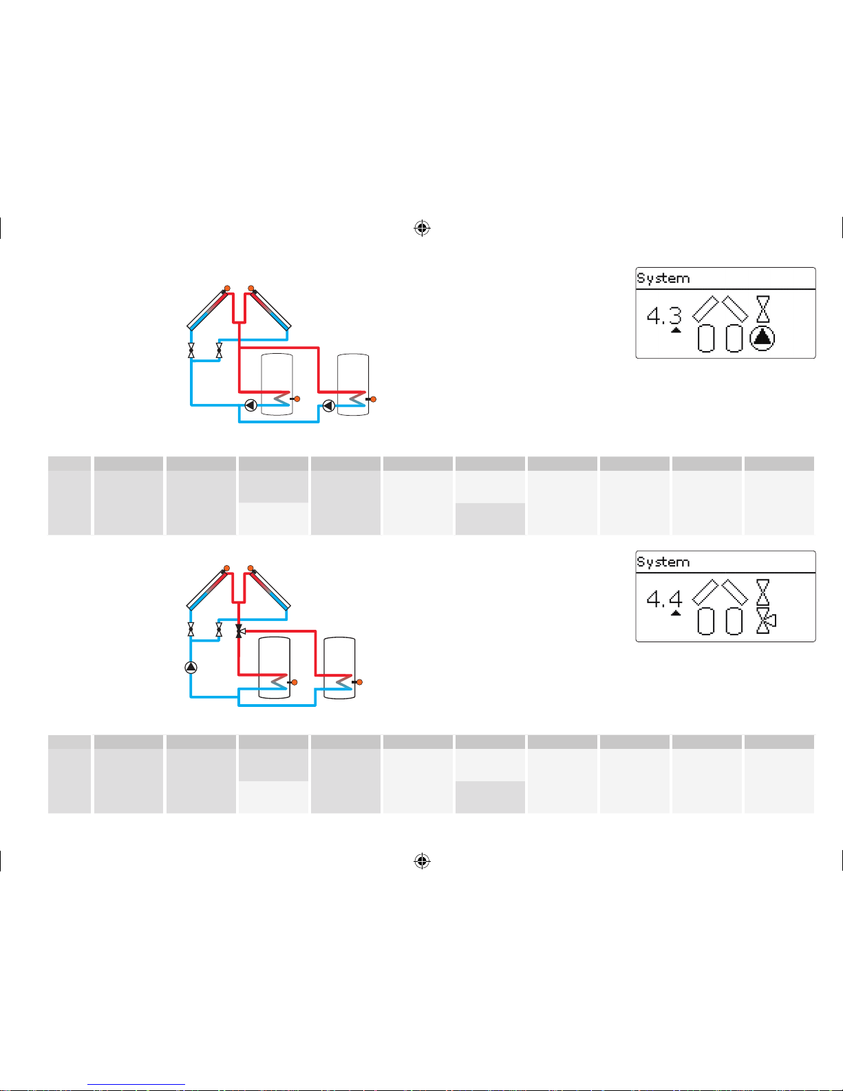
System 4 variant 3
R1
R2
S1 S6
R3
R4
S4S2
Relay / sensor allocation
1 2 3 4 5 6 7 8 9 10-14
Relay
2PV coll. 1 2PV coll. 2
Solar pump
store 1
Solar pump
store 2
Optional
function
Optional
function
Optional
function
Optional
function
Optional
function
Optional
function
Sensor
Collector 1 Store 1 base Free Store 2 base Free Collector 2 Free Free Free Free
System 4 variant 4
R1
R2
S2 S4
R4
S1 S6
R3
Relay / sensor allocation
1 2 3 4 5 6 7 8 9 10-14
Relay
2PV coll. 1 2PV coll. 1 Solar pump
3PV
store 1
Optional
function
Optional
function
Optional
function
Optional
function
Optional
function
Optional
function
Sensor
Collector 1 Store 1 base Free Store 2 base Free Collector 2 Free Free Free Free
295931-36390-8667 SOM 8 plus_en.indb 19 20.10.2011 13:14:28
20
System 5 variant 1
S1
R1
R2 R3 R4
S2 S4 S5
Relay / sensor allocation
1 2 3 4 5 6 7 8 9 10-14
Relay
Solar pump
2PV
store 1
2PV
store 2
2PV
store 3
Optional
function
Optional
function
Optional
function
Optional
function
Optional
function
Optional
function
Sensor
Collector 1 Store 1 base Free Store 2 base Store 3 base Free Free Free Free Free
System 5 variant 2
S1
R1 R2 R3
S5S4S2
Relay / sensor allocation
1 2 3 4 5 6 7 8 9 10-14
Relay
Solar pump
store 1
Solar pump
store 2
Solar pump
store 3
Optional
function
Optional
function
Optional
function
Optional
function
Optional
function
Optional
function
Optional
function
Sensor
Collector 1 Store 1 base Free Store 2 base Store 3 base Free Free Free Free Free
295931-36390-8667 SOM 8 plus_en.indb 20 20.10.2011 13:14:28
21
System 5 variant 3
Relay / sensor allocation
1 2 3 4 5 6 7 8 9 10-14
Relay
Solar pump
3PV
store 1
3PV
store 2
Optional
function
Optional
function
Optional
function
Optional
function
Optional
function
Optional
function
Optional
function
Sensor
Collector 1 Store 1 base Free Store 2 base Store 3 base Free Free Free Free Free
S1
S2 S4 S5
R1
R3
R2
System 6 variant 1
R1 R2
S6S1
S2 S4 S5
R5R4R3
Relay / sensor allocation
1 2 3 4 5 6 7 8 9 10-14
Relay
Pump coll. 1 Pump coll. 2 2PV store 1 2PV store 2 2PV store 3
Optional
function
Optional
function
Optional
function
Optional
function
Optional
function
Sensor
Collector 1 Store 1 base Free Store 2 base Store 3 base Collector 2 Free Free Free Free
295931-36390-8667 SOM 8 plus_en.indb 21 20.10.2011 13:14:29
22
System 6 variant 2
S1 S6
S2 S4 S5
R1 R2 R3
R5R4
Relay / sensor allocation
1 2 3 4 5 6 7 8 9 10-14
Relay
Solar pump
store 1
Solar pump
store 2
Solar pump
store 3
2PV coll. 1 2PV coll. 2
Optional
function
Optional
function
Optional
function
Optional
function
Optional
function
Sensor
Collector 1 Store 1 base Free Store 2 base Store 3 base Collector 2 Free Free Free Free
System 6 variant 3
S2 S4 S5
S1 S6
R1 R2
R3
R4 R5 R6
Relay / sensor allocation
1 2 3 4 5 6 7 8 9 10-14
Relay
2PV coll. 1 2PV coll. 2 Solar pump
2PV
store 1
2PV
store 2
2PV
store 3
Optional
function
Optional
function
Optional
function
Optional
function
Sensor
Collector 1 Store 1 base Free Store 2 base Store 3 base Collector 2 Free Free Free Free
295931-36390-8667 SOM 8 plus_en.indb 22 20.10.2011 13:14:29
23
S2 S4 S5
S1 S6
R1
R2
R3 R4
System 6 variant 4
Relay / sensor allocation
1 2 3 4 5 6 7 8 9 10-14
Relay
Pump coll. 1 Pump coll. 2 3PV store 1 3PV store 2
Optional
function
Optional
function
Optional
function
Optional
function
Optional
function
Optional
function
Sensor
Collector 1 Store 1 base Free Store 2 base Store 3 base Collector 2 Free Free Free Free
System 6 variant 5
Relay / sensor allocation
1 2 3 4 5 6 7 8 9 10-14
Relay
2PV coll. 1 2PV coll. 2 Solar pump
3PV
Store 1
3PV
Store 2
Optional
function
Optional
function
Optional
function
Optional
function
Optional
function
Sensor
Collector 1 Store 1 base Free Store 2 base Store 3 base Collector 2 Free Free Free Free
S1
S2 S4 S5
R3
R5
R4
R2
S6
R1
295931-36390-8667 SOM 8 plus_en.indb 23 20.10.2011 13:14:30
24
System 7 variant 1
S2 S4 S5
S1
S6
R1
R2 R3 R4 R5
Relay / sensor allocation
1 2 3 4 5 6 7 8 9 10-14
Relay
Solar pump
2PV
store 1
2PV
store 2
2PV
store 3
2PV
store 4
Optional
function
Optional
function
Optional
function
Optional
function
Optional
function
Sensor
Collector 1 Store 1 base Free Store 2 base Store 3 base Store 4 base Free Free Free Free
System 7 variant 2
S2 S4 S5
S1
S6
R1
R2 R3 R4
Relay / sensor allocation
1 2 3 4 5 6 7 8 9 10-14
Relay
Solar pump
3PV
store 1
3PV
store 2
3PV
store 3
Optional
function
Optional
function
Optional
function
Optional
function
Optional
function
Optional
function
Sensor
Collector 1 Store 1 base Free Store 2 base Store 3 base Store 4 base Free Free Free Free
295931-36390-8667 SOM 8 plus_en.indb 24 20.10.2011 13:14:30
25
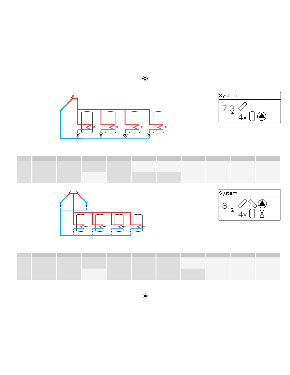
System 7 variant 3
Relay / sensor allocation
1 2 3 4 5 6 7 8 9 10-14
Relay
Solar pump
store 1
Solar pump
store 2
Solar pump
store 3
Solar pump
store 4
Optional
function
Optional
function
Optional
function
Optional
function
Optional
function
Optional
function
Sensor
Collector 1 Store 1 base Free Store 2 base Store 3 base Store 4 base Free Free Free Free
S1
S2 S4 S5 S6
R1 R2 R3 R4
System 8 variant 1
Relay / sensor allocation
1 2 3 4 5 6 7 8 9 10-14
Relay
Pump coll. 1 Pump coll. 2
2PV
store 1
2PV
store 2
2PV
store 3
2PV
store 4
Optional
function
Optional
function
Optional
function
Optional
function
Sensor
Collector 1 Store 1 base Free Store 2 base Store 3 base Collector 2 Store 4 base Free Free Free
S1
S2 S4 S5 S7
R4
R5
R3
R2
S6
R1
R6
295931-36390-8667 SOM 8 plus_en.indb 25 20.10.2011 13:14:30

26
System 8 variant 2
Relay / sensor allocation
1 2 3 4 5 6 7 8 9 10-14
Relay
Pump coll. 1 Pump coll. 2
3PV
store 1
3PV
store 2
3PV
store 3
Optional
function
Optional
function
Optional
function
Optional
function
Optional
function
Sensor
Collector 1 Store 1 base Free Store 2 base Store 3 base Collector 2 Store 4 base Free Free Free
S1
S2 S4 S5 S7
R3
R2
S6
R1
R4
R5
System 8 variant 3
Relay / sensor allocation
1 2 3 4 5 6 7 8 9 10-14
Relay
Solar pump
store 1
Solar pump
store 2
Solar pump
store 3
Solar pump
store 4
2PV coll. 1 2PV coll. 2
Optional
function
Optional
function
Optional
function
Optional
function
Sensor
Collector 1 Store 1 base Free Store 2 base Store 3 base Collector 2 Store 4 base Free Free Free
S1
S2 S4 S5 S7
R2
R3
R1
R6
S6
R5
R4
295931-36390-8667 SOM 8 plus_en.indb 26 20.10.2011 13:14:31
 Loading...