

STIEBEL ELTRON SOM 7 PLUS Operation And Installation
OPERATION AND INSTALLATION
SOLAR CONTROLLER
» SOM 7 PLUS
!
ATTENTION: INSTALLING THE CONTROLLER WITH THE
DEFAULT SETTINGS IS NOT RECOMMENDED. IN
ORDER TO PREVENT OVERHEATING OF THE SYSTEM
HEAT EXCHANGER FLUID OR DOMESTIC HOT WATER
THE SETTINGS “OCC” AND “OSTC” SHOULD BE SET
TO “ON” AND THE SETTING “EM” SHOULD BE RAISED
TO 290 °F.
2
Safety advice:
Please read the following information carefully before
installing and operating the controller. In this way damage
to the solar system caused by wrong installation will be
avoided. Please make sure that the mounting is adapted to
the characteristics of the building, that the local regulations
are respected and is conform with the technical rules.
Description of symbols
Signal words describe the danger that may occur, when it is
not avoided.
Warning means that injury, possibly life-threatening injury,
can occur.
Attention means that damage to the appliance can occur.
Information about the product
Proper usage
The solar controller is designed for use in solar thermal
and heating systems in compliance with the technical data
specified in these instructions.
Improper use excludes all liability claims.
Note
Strong elec tromagnetic f ields can impair the
function of the controller.
Î Make sure the controller as well as the system
are not exposed to strong electromagnetic
fields.
WARNING! Warnings are indicated with a warning
triangle!
They contain information on how to
avoid the danger described.
Note
Notes are indicated with an i nformat ion
symbol.
Subject to technical change. Errors excepted.
Please pay attention to the following safety advice in order to
avoid danger and damage to people and property.
Instructions:
Attention should be paid to
• valid national and local standards and regulations
• respective valid standards and directives
Equipment to be installed and used in accordance with the
rules of the National Electrical Code (NEC) or with Canadian
Electrical Code (CEC), Part I.
These instructions are exclusively addressed to authorized
skilled personnel.
• Only qualified electricians should carry out installation
and maintenance work.
• Initial installation should be carried out by qualified personnel
Î Arrows indicate instruction steps that should be carried
out.
General
Contents
General .............................................................................2
Overview ...........................................................................3
1. Installation ..................................................................4
1.1 Mounting ..................................................................... 4
1.2 Electrical connection ....................................................4
1.3 Data communication/ Bus ............................................5
1.4 Terminal allocation in the different system layouts ....... 6
System layout 1 ............................................................ 6
System layout 2 ............................................................ 8
System-specific functions .......................................... 10
System layout 3 .......................................................... 12
System-specific functions .......................................... 14
System layout 4 .......................................................... 16
System layout 5 .......................................................... 18
System layout 6 .......................................................... 20
System layout 7 .......................................................... 22
System layout 8 .......................................................... 24
System-specific functions .......................................... 26
System layout 9 .......................................................... 28
System layout 10 ........................................................ 30
2. Operation and function ..............................................32
2.1 Push buttons .............................................................. 32
2.2 System monitoring display ......................................... 32
2.3 Flashing codes ........................................................... 33
3. Commissioning........................................................... 34
4. Channel overview ...................................................... 37
4.1 Display channels ........................................................ 37
4.2 Adjustment channels .................................................. 39
5. Troubleshooting ......................................................... 47
5.1 Various ...................................................................... 48
3
!
• System-monitoring-display
• Up to 4 Pt1000 temperature sensors
• 2 semiconductor relays for pump speed control
• 10 basic system layouts to choose from
• Energy metering
• VBus
®
• Function control
• Thermostat function (time controlled)
• Control of the system by ServiceCenter
software possible
• User-friendly operation
• Housing with outstanding design
• Extra-low power consumption
2.6"
66 mm
4.3"
110 mm
6.8"
172 mm
1.1"
28 mm
0.4" / 11 mm
1.9" / 47 mm
0.5" / 13 mm
6.1"
155 mm
Included with the SOM 7 plus:
1 × SOM 7 plus
1 × accessory bag
1 × spare fuse T4A
2 × screws and wall plugs
4 × strain relief and screws
1 × manual
Additionally enclosed in the full kit:
4 × sensor PT 1000
1 x heat conducting paste
Technical data
Housing: plastic, PC-ABS and PMMA
Protection type: IP 20 / EN 60529
Ambient temp.:
32 ... 104 °F
[0 ... 40 °C]
Size:
6.8" × 4.3" × 1.9"
172 × 110 × 46 mm
Mounting: wall mounting, mounting into
patch-panels is possible
Display: System screen for syste m
visualization, 16 -segment disp lay,
7-segment display, 8 symbols for system
status and operating control lamp
Operation: by 3 push buttons at the front
of the housing
Functions: Differential temperature
controller with optional add-on system
functions. Func ti on con trol, operating
hours counter for solar pump, evacuated
tube collector function, pump speed
control, thermostat function, drainback
and booster option, and energy metering.
Inputs:
for 4 Pt1000 temperature sensors
Outputs: 2 semiconductor relays
Bus: VBus
®
Power supply:
100 ... 240 V~
Standby power consumption:
< 1 W
Switching capacities:
R1: 1 (1) A 100 ... 240 V~
(semiconductor relay)
R2: 1 (1) A 100 ... 240 V~
(semiconductor relay)
Overview
4
display
push button
fuse 4A
cable conduits with strain
relief
cover
1.1 Mounting
The unit must only be installed
• in a dry interior location
• in a non-hazardous location
• away from electromagnetic fields
The controller must additionally be supplied from a doublepole switch with contact gap of at least 0.12".
Route sensor cables and power supply cables separately.
Î Unscrew the cross-head screw from the cover and remove
it along with the cover from the housing
Î Mark the upper fastening point on the wall and drill
Î Fasten the enclosed wall plug and screw leaving the head
protruding
Î Hang the housing from the upper fastening point and
mark the lower fastening point through the hole in the
terminal box (centers 5.1")
Î Drill and insert the lower wall plug
Î Fasten the housing to the wall with lower fastening screw
and tighten
Î Complete wiring connections in accordance with terminal
allocations, see chap. 1.2 “Electrical connection”
Î Place the cover back onto the housing
Î Fasten the cover by means of the cross-head screw
1. Installation
.
„
upper fastening
lower fastening
VBus
®
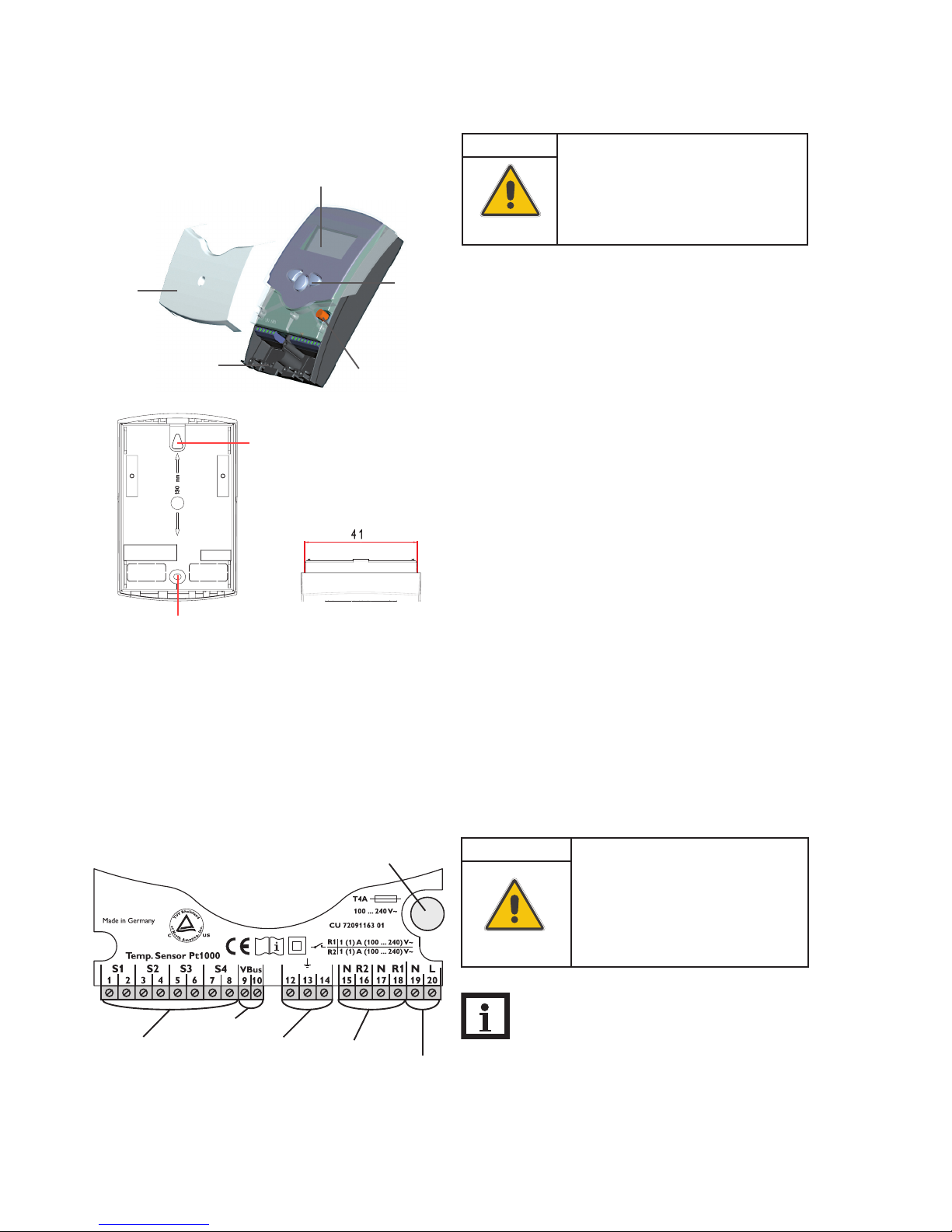
1.2 Electrical connection
power supply terminals
fuse
load terminalssensor terminal
ground terminal
Note:
The minimum pump speed must be set to 100% when
auxiliary relays or valves are connected.
WARNING! Electric shock!
Opening the housing will expose live
parts!
Î Switch off power supply and disconnect
the device from power supply before
opening the housing!
ATTENTION! ESD damage!
Electro static dis charge can lead to
damage to electronic components!
Î Take c are to dischar ge properly
before touching the inside of the
device. To do so, touch a grounded
surface such as a radiator or tap!
5
1.3 Data communication/ Bus
The controller is equipped with a VBus® for data transfer with
and energy supply to external modules. The connection is
carried out at the terminals marked “VBus” (either polarity).
One or more VBus® modules can be connected via this data
bus.
By means of an interface adapter, the controller can be
connected to a PC or a computer network.
VBus
®
connection terminals
Connecting the device to the power supply must always be
the last step of the installation!
The power supply to the controller must be carried out via
an external power switch (last step!). The supply voltage
must be 100 ... 240 V~ (50 ... 60 Hz). Flexible cables must be
attached to the housing with the enclosed strain relief and
the corresponding screws.
The controller is equipped with two semiconductor relays,
to which loads such as pumps, valves etc. can be connected:
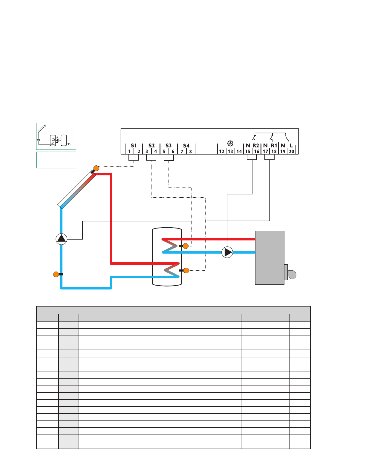
• Relay 1
18 = conductor R1
17 = neutral conductor N
13 = ground conductor
• Relay 2
16 = conductor R2
15 = neutral conductor N
14 = ground conductor
The power supply is to be carried out at the terminals:
19 = neutral conductor N
20 = conductor L
12 = ground terminal
The temperature sensors (S1 up to S4) are to be connected
to the following terminals with either polarity:
1 / 2 = Sensor 1 (e.g. Sensor collector 1)
3 / 4 = Sensor 2 (e.g. Sensor tank 1)
5 / 6 = Sensor 3 (e.g. Sensor tank top)
7 / 8 = Sensor 4 (e.g. Sensor return)
All Pt1000 temperature sensors are equipped with a platinum
measuring element in their tip. The electrical resistance of the
measuring element changes in relation to the temperature
(see table in chap. 5).
LNR1NR2N
201918171615141312
1 (1) A (1100 ... 240) V~
(1) A (100 ... 240)V~
R1
R2
1 2
S1 S2 S3
3 4 5 6
Temp. Sensor
Pt1000
S4
7 8
Sensor terminals S1 ... S4
Grounding and load terminals
6
S1
S2
S4 / TR
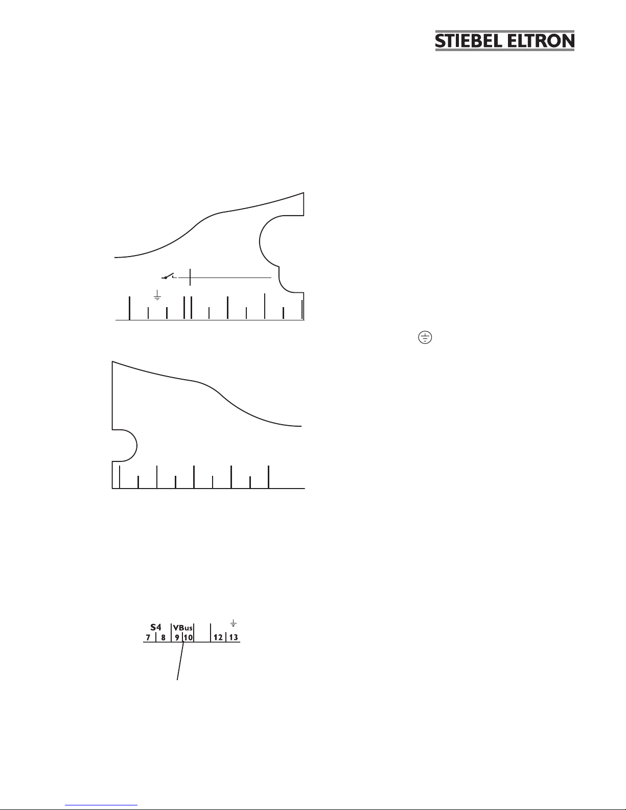
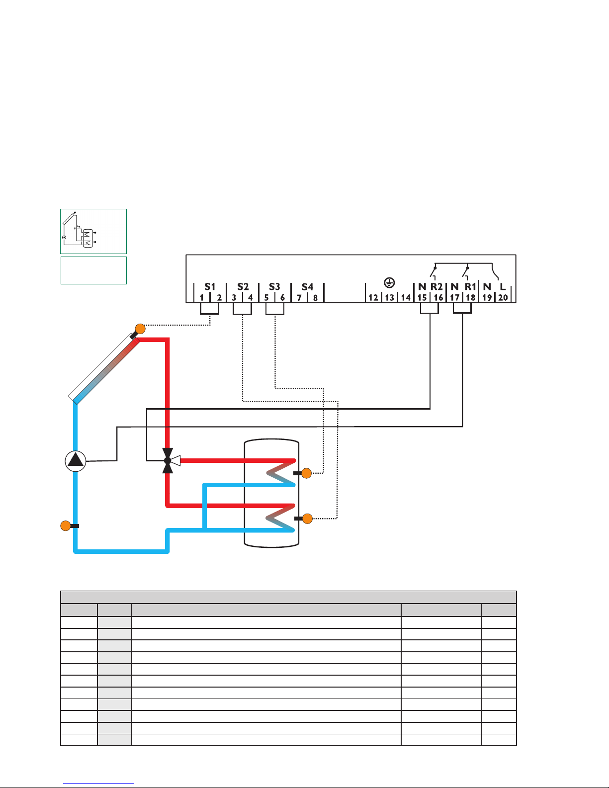
System layout 1
The controller calculates the temperature difference between
collector sensor S1 and tank sensor S2. If the difference is
larger than or identical to the adjusted switch-on temperature
difference (DT O), the solar pump will be operated by relay 1,
and the tank will be loaded until the switch-off temperature
difference (DT F) or the maximum tank temperature (S MX)
is reached.
R1
Arr 1
S3
1.4 Terminal allocation in the different system layouts
Display Channels
Channel Description Terminal Page
INIT
x*
ODB initialization active - 37
FLL
x*
ODB filling time active - 37
STAB
x*
ODB stabilization in progress - 37
COL x Temperature collector S1 37
TST x Temperature tank S2 37
S3 x Temperature sensor 3 S3 37
S4 x Temperature sensor 4 S4 37
TR x* Temperature return sensor S4 37
n % x Pump speed R1 R1 38
hP x Operating hours R1 R1 38
hP1 x* Operating hours R1 (if OBST is activated) R1 38
hP2 x* Operating hours R2 (if OBST is activated) R2 38
kWh x* Heat quantity kWh - 38
MWh x* Heat quantity MWh - 38
TIME x Time - 34
Sen s ors S3 and S4 can option ally be co n n ected for
measurement purposes.
If energy metering (OHQM) is activated, sensor S4 has to be
connected as return sensor.
If the drainback option (ODB) is activated, relay 2 can be used
to operate a booster pump by activating the booster function
(OBST).
S1
S3
S2
S4/TR
R1 R2
exemplary
Drainback system layout
(with booster pump)

7
Legend:
Symbol Specification
x Channel is available
x* Channel is available if the corresponding option is activated.
s* System-specific channel, only available if the corresponding option is activated
Adjustment Channels
Channel Description Factory setting Page
Arr x System 1 39
DT O x Switch-on temperature difference 12.0 °Ra [6.0 K] 39
DT F x Switch-off temperature difference 8.0 °Ra [4.0 K] 39
DT S x Nominal temperature difference 20.0 °Ra [10.0 K] 39
RIS x Rise control R1 4 °Ra [2 K] 39
nMN x Minimum pump speed 30 % 39
S MX x Maximum tank temperature 140 °F [60 °C] 40
EM x
Emergency temperature collector 270 °F [130 °C] 40
Emergency temperature collector if ODB is activated: 200 °F [95 °C] 40
OCC x Option collector cooling
OFF 41
CMX x* Maximum collector temperature
230 °F [110 °C] 41
OSYC x Option system cooling OFF 41
DTCO x* Cooling switch-on temperature difference
40.0 °Ra [20.0 K]
41
DTCF x* Cooling switch-off temperature difference
30.0 °Ra [15.0 K]
41
OSTC x Option tank cooling OFF 42
OHOL x* Option holiday cooling OFF 42
THOL x* Holiday cooling temperature 110 °F [40 °C] 42
OCN x Option minimum limitation OFF 42
CMN x* Minimum collector temperature 50 °F [10 °C] 42
OCF x Option antifreeze OFF 42
CFR x* Antifreeze temperature 40.0 °F [4.0 °C] 42
O TC x Option tube collector OFF 44
TCST x* OTC starting time 07:00 44
TCEN x* OTC ending time 19:00 44
TCRU x* OTC runtime 30 s 44
TCIN x* OTC standstill interval 30 min 44
OHQM x Option energy metering OFF 44
FMAX x* Maximum flow 6.0 l 44
MEDT x* Antifreeze type 1 44
MED% x* Antifreeze concentration (only if MEDT = propylene or ethylene) 45 % 44
ODB x Drainback option OFF 45
tDTO x* ODB switch-on condition - time period 60 s 45
tFLL x* ODB filling time 5.0 min 45
tSTB x* ODB stabilization time 2.0 min 45
OBST s* Option booster function OFF 45
MAN1 x Manual operation R1 Auto 46
MAN2 x Manual operation R2 Auto 46
LANG x Language En 46
UNIT x Temperature unit °C 46
RESE x Reset - back to factory defaults 46
W0050100 Version number
8
S1
S3
S4
R1
R2
S2
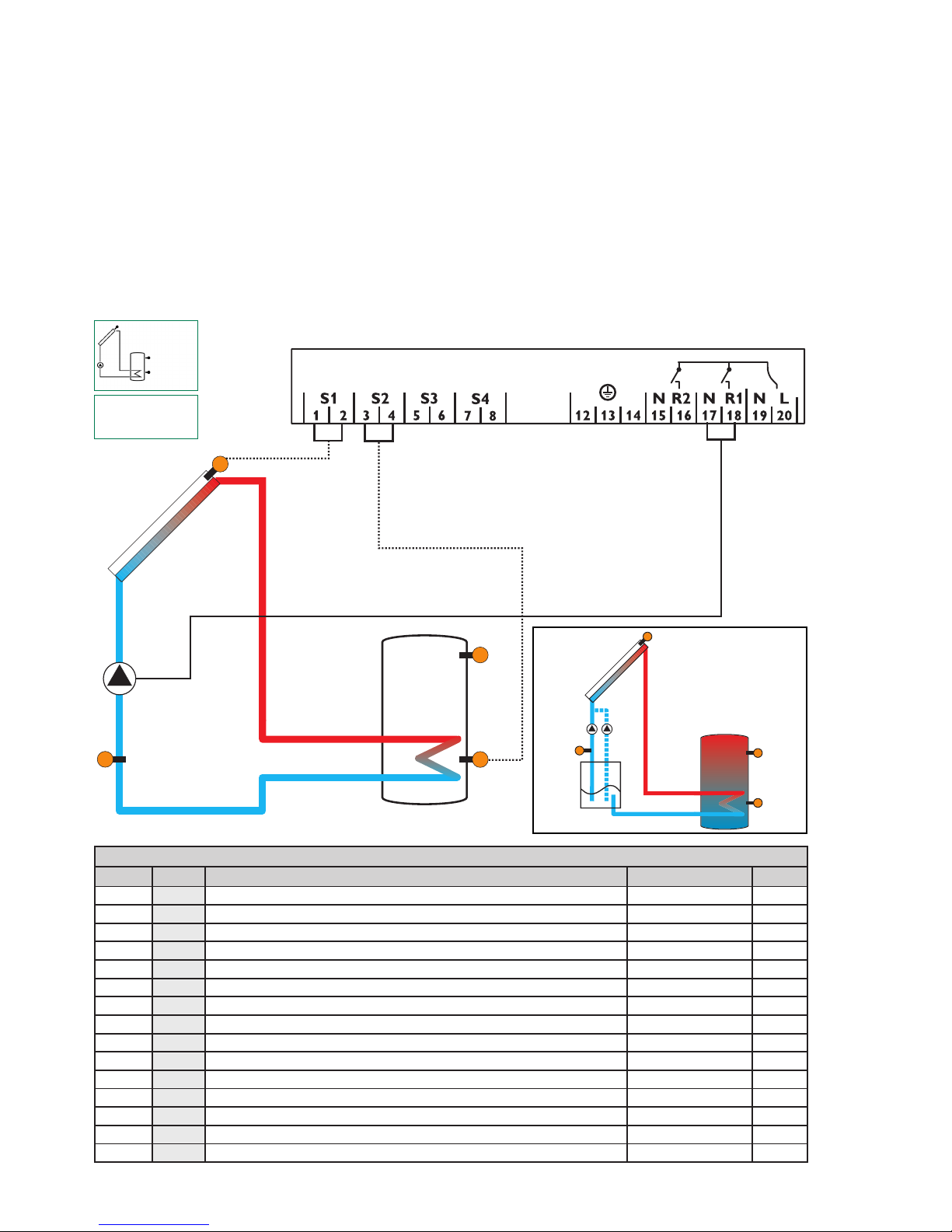
System layout 2
The controller calculates the temperature difference between
collector sensor S1 and tank sensor S2. If the difference is
larger than or identical to the adjusted switch-on temperature
difference (DT O), the solar pump will be operated by relay 1,
and the tank will be loaded until the switch-off temperature
difference (DT F) or the maximum tank temperature (S MX)
is reached.
Arr 2
Tank 1
Tank 2
Display Channels
Channel Description Terminal Page
INIT
x*
ODB initialization active - 37
FLL
x*
ODB filling time active - 37
STAB
x*
ODB stabilization in progress - 37
COL x Temperature collector S1 37
TST1 x Temperature tank 1 bottom S2 37
TSTT x Temperature tank 1 at the top S3 37
TST2 x Temperature tank 2 bottom S4 37
n1 % x Pump speed R1 R1 38
n2 % x Pump speed R2 R2 38
h P1 x Operating hours R1 R1 38
h P2 x Operating hours R2 R2 38
TIME x Time - 34
Heat exchange from tank 1 to tank 2 will be operated by relay
2, if the temperature difference between sensors S3 and S4 is
larger than or identical to the adjusted switch-on temperature
difference (DT3O), until the adjusted minimum (MN3O) and
maximum (MX3O) temperature thresholds of the respective
tanks are reached.

9
Legend:
Adjustment Channels
Channel Description Factory setting Page
Arr x System 2 39
DT O x Switch-on temperature difference 12.0 °Ra [6.0 K] 39
DT F x Switch-off temperature difference 8.0 °Ra [4.0 K] 39
DT S x Nominal temperature difference 20.0 °Ra [10.0 K] 39
RIS x Rise control R1 4 °Ra [2 K] 39
n1MN x Minimum pump speed R1 30 % 39
S MX x Maximum tank temperature 140 °F [60 °C] 40
n2MN s Minimum pump speed R2 30 % 10
EM x
Emergency temperature collector 270 °F [130 °C] 40
Emergency temperature collector if ODB is activated: 200 °F [95 °C] 40
OCC x Option collector cooling
OFF 41
CMX x* Maximum collector temperature
230 °F [110 °C] 41
OSYC x Option system cooling OFF 41
DTCO x* Cooling switch-on temperature difference
40.0 °Ra [20.0 K]
41
DTCF x* Cooling switch-off temperature difference
30.0 °Ra [15.0 K]
41
OSTC x Option tank cooling OFF 42
OHOL x* Option holiday cooling OFF 42
THOL x* Holiday cooling temperature 110 °F [40 °C] 42
OCN x Option minimum limitation OFF 42
CMN x* Minimum collector temperature 50 °F [10 °C] 42
OCF x Option antifreeze OFF 42
CFR x* Antifreeze temperature 40.0 °F [4.0 °C] 42
O TC x Option tube collector OFF 44
TCST x* OTC starting time 07:00 44
TCEN x* OTC ending time 19:00 44
TCRU x* OTC runtime 30 s 44
TCIN x* OTC standstill interval 30 min 44
DT3O s Switch-on temperature difference 3
12.0 °Ra [6.0 K] 10
DT3F s Switch-off temperature difference 3
8.0 °Ra [4.0 K] 10
DT3S s Nominal temperature difference 3
20.0 °Ra [10.0 K] 10
RIS3 s Rise control R2
4 °Ra [2 K] 10
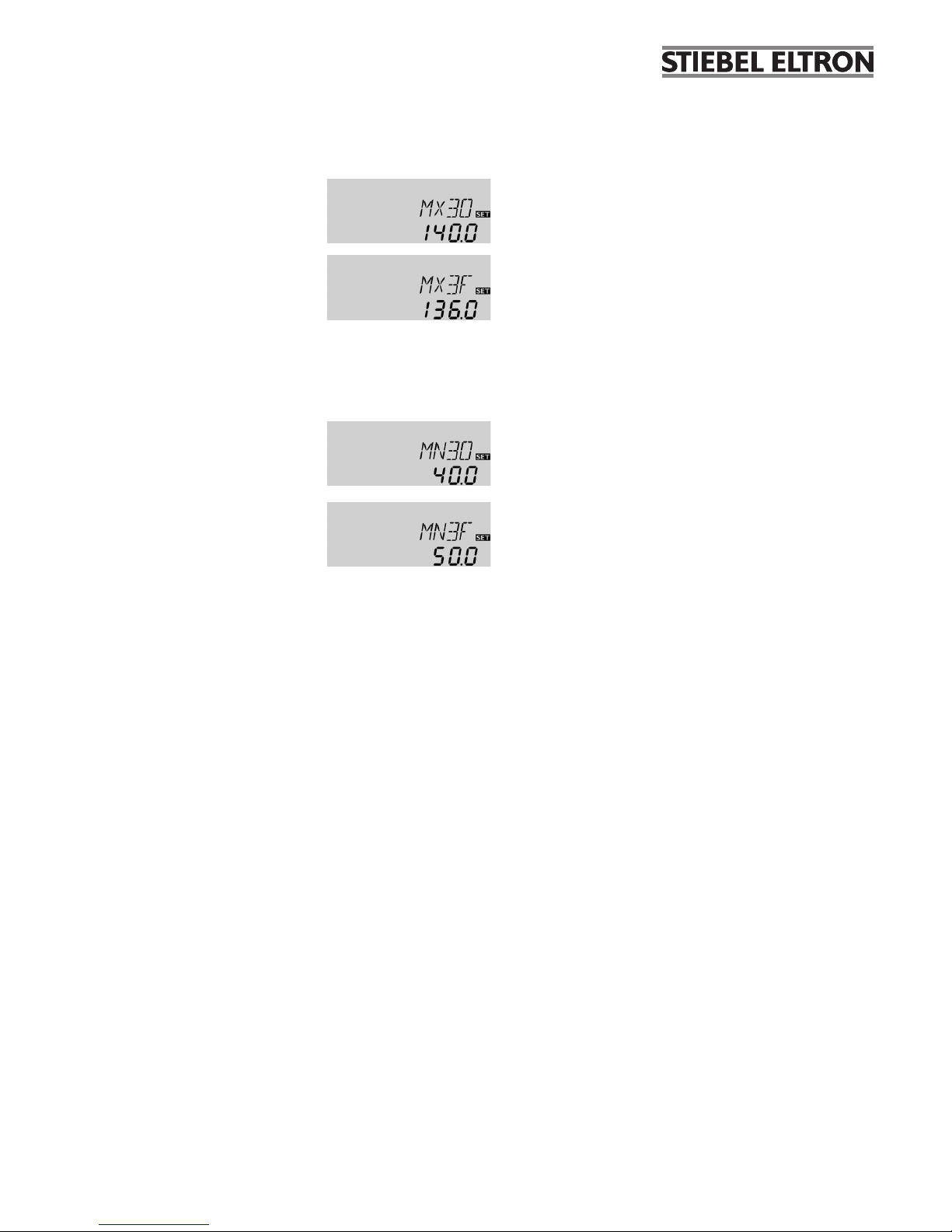
MX3O s Switch-on treshold for maximum temperature 140.0 °F [60.0 °C] 11
MX3F s Switch-off treshold for maximum temperature 136.0 °F [58.0 °C] 11
MN3O s Switch-on treshold for minimum temperature 40.0 °F [5.0 °C] 11
MN3F s Switch-off treshold for minimum temperature 50.0 °F [10.0 °C] 11
ODB x Drainback option OFF 45
tDTO x* ODB switch-on condition - time period 60 s 45
tFLL x* ODB filling time 5.0 min 45
tSTB x* ODB stabilization time 2.0 min 45
MAN1 x Manual operation R1 Auto 46
MAN2 x Manual operation R2 Auto 46
LANG x Language En 46
UNIT x Temperature unit °C 46
RESE x Reset - back to factory defaults 46
W0050100 Version number
Symbol Specification
x Channel is available
x* Channel is available if the corresponding option is activated.
s Channel is specifically available in this system layout
10
∆T control for the heat exchange between 2 tanks
DT3O:
Switch-on temperature diff.
Adjustment range: 2.0 ... 40.0°Ra
[1.0 ... 20.0 K]
in steps of 1 °Ra [0.5 K]
Factory setting: 12.0°Ra
[6.0 K]
DT3F:
Switch-off temperature diff.
Adjustment range: 1.0 ... 39.0°Ra
[0.5 ... 19.5 K]
in steps of 1 °Ra [0.5 K]
Factory setting: 8.0°Ra
[4.0 K]
Reference sensors for this function are S3 and S4.
Insystem layout 2 thecontroller isequipped with an additional differential control for heat exchange between
two tanks. The basic differential function is adjusted using
the switch-on (DT3O) and switch-off (DT3F) temperature
differences.
When the temp erature difference exce eds the sw itchon temperature difference, relay 2 switches on. If the
temperature difference then falls below the adjusted switchoff temperature difference, relay 2 switches off.
Note:
The switch-on temperature difference must be
at least 1 °Ra [0.5 K] higher than the switch-off
tempe rature difference.
DT3S:
Nominal temperature difference
Adjustment range: 3.0 ... 60.0 °Ra
[1.5 ... 30.0 K]
in steps of 1 °Ra [0.5 K]
Factory setting: 20.0 °Ra
[10.0 K]
RIS3:
Rise
Adjustment range:
2 ... 40 °Ra [1 ... 20 K]
in steps of 2 °Ra [1 K]
Factory setting: 4 °Ra [2 K]
Pump speed control
A relative minimum pump speed can be allocated to the
output R2 via the adjustment channel n2MN.
n2MN:
Pump speed control
Adjustment range: 30 ... 100
in steps of 5 %
Factory setting: 30
Note:
When loads which are not speed-controlled (e.g.
valves) are used, the value must be set to 100% in
order to deactivate pump speed control.
Minimum pump speed
When the switch-on temperature difference is reached, the
pump is activated at full speed for 10 seconds. Then, the speed
is reduced to the minimum pump speed value (n2MN).
If the temperature difference reaches the adjusted nominal
temperature difference (DT3S), the pump speed increases by one
step (10%). If the difference increases by the adjustable rise value,
the pump speed increases by 10% respectively until the maximum
pump speed of 100% is reached. The response of the controller
can be adapted via the parameter RIS3.
Note:
The nominal temperature difference must be
at least 1 °Ra [0.5 K] higher than the switch-on
tempe rature difference.
Note:
For pump speed control of the heat exchange
pump, the operation mode of relay 2 (MAN2) must
be set to Auto.
System-specific functions
The following adjustments are used for the specific function
in system layout 2.
11
Maximum temperature limitation
MX3O / MX3F:
Maximum temperature limitation
Adjustment range:
30.0 ... 200.0°F
[0.0 ... 95.0 °C]
in steps of 1 °Ra [0.5 K]
Factory setting:
MX3O: 140.0°F [60.0 °C]
MX3F: 136.0°F [58.0 °C]
Minimum temperature limitation
MN3O / MN3F:
Minimum temperature limitation
Adjustment range:
30.0 ... 190.0°F
[0.0 ... 90.0 °C]
in steps of 1 °Ra [0.5 K]
Factory setting (Arr = 2 only):
MN3O: 40.0°F [5.0 °C]
MN3F: 50.0°F [10.0 °C]
Minimum and maximum temperature limits can be set for
the heat exchange function.
The maximum temperature limitation uses sensor 4 as
reference sensor.
The maximum temperature limitation function provides a
maximum tem perature setting, usually to reduce scald risk
in a storage tank. If MX3O is exceeded, relay2 is switched off
until the temperature at sensor 4 falls below MX3F.
The minimum temperature limitation uses sensor 3 as
reference sensor.
The minimum temperature limitation function provides a
minimum tem perature setting for the heat source in system
layout 2. If the temperature at sensor 3 falls below MN3O,
relay2 is switched of f until the temperature at sensor 3
exceeds MN3F.
Both switch-on and switch-off temperature differences
DT3O and DT3F are valid for the maximum and minimum
temperature limitation.
12
R2
S1
S2
R1
S3
S4 / TR
System layout 3
The controller calculates the temperature difference between
collector sensor S1 and tank sensor S2. If the difference is
larger than or identical to the adjusted switch-on temperature
difference (DT O), the solar pump will be operated by relay 1,
and the tank will be loaded until the switch-off temperature
difference (DT F) or the maximum tank temperature (S MX)
is reached.
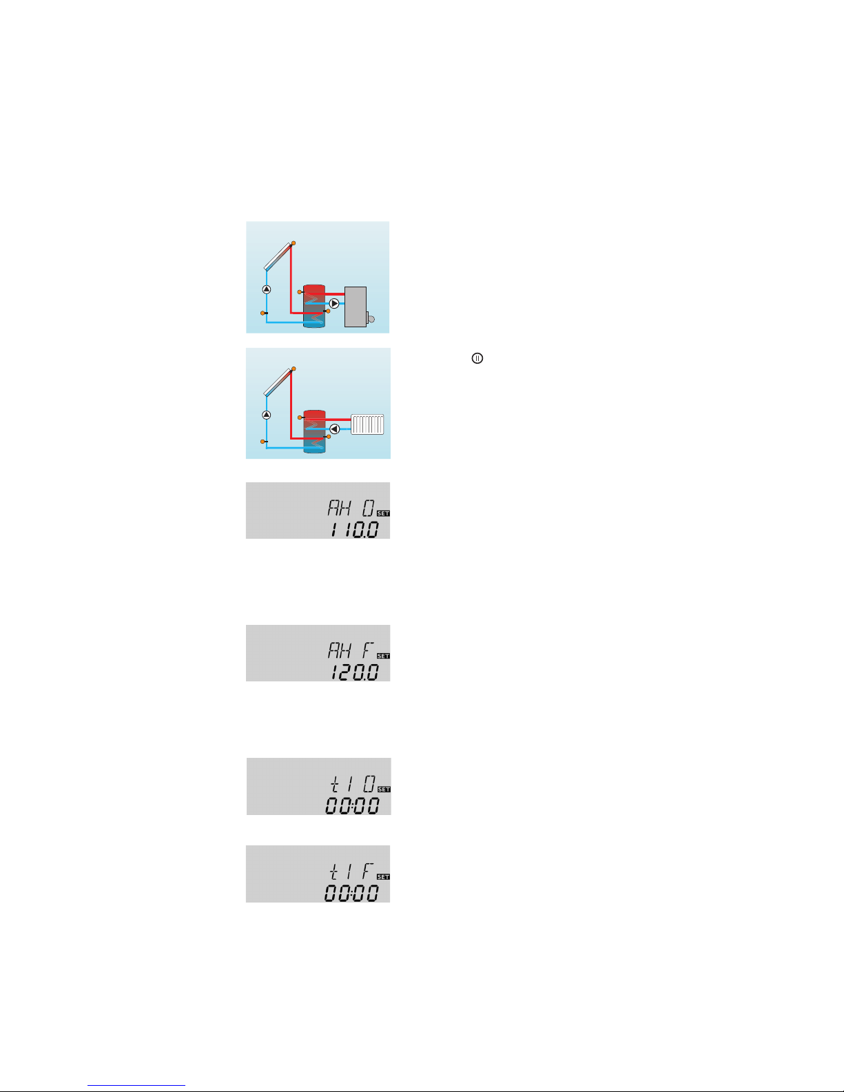
Sensor S3 is used for a thermostatic function, which operates
Arr 3
Display Channels
Channel Description Terminal Page
INIT
x*
ODB initialization active - 37
FLL
x*
ODB filling time active - 37
STAB
x*
ODB stabilization in progress - 37
COL x Temperature collector S1 37
TSTB x Temperature tank 1 bottom S2 37
TSTT x Temperature tank 1 at the top S3 37
TDIS
s*
Thermal disinfection temperature S3 37
S4 x Temperature sensor 4 S4 37
TR x* Temperature return sensor S4 37
n1 % x Pump speed R1 R1 38
h P1 x Operating hours R1 R1 38
h P2 x Operating hours R2 R2 38
kWh
x*
Heat quantity kWh - 38
MWh
x*
Heat quantity MWh - 38
CDIS
s*
Countdown of monitoring period - 38
SDIS
s*
Starting time display - 38
DDIS
s*
Heating period display - 38
TIME x Time - 34
relay 2 for backup heating or heat dump purposes, when
the adjusted thermostat switch-on temperature (AHO) is
reached. This function can optionally be combined with up
to three adjustable time frames.
Sensor S3 can also be optionally used as a reference sensor
for the thermal disinfection function OTD.
Sensor S4 can optionally be connected for measurement
purposes. If energy metering (OHQM) is activated, sensor S4
has to be connected as return sensor.

13
Adjustment Channels
Channel Description Factory setting Page
Arr x System 3 39
DT O x Switch-on temperature difference 12.0 °Ra [6.0 K] 39
DT F x Switch-off temperature difference 8.0 °Ra [4.0 K] 39
DT S x Nominal temperature difference 20.0 °Ra [10.0 K] 39
RIS x Rise control R1 4 °Ra [2 K] 39
n1MN x Minimum pump speed R1 30 % 39
S MX x Maximum tank temperature 140 °F [60 °C] 40
EM x
Emergency temperature collector 270 °F [130 °C] 40
Emergency temperature collector if ODB is activated: 200 °F [95 °C] 40
OCC x Option collector cooling
OFF 41
CMX x* Maximum collector temperature
230 °F [110 °C] 41
OSYC x Option system cooling OFF 41
DTCO x* Cooling switch-on temperature difference
40.0 °Ra [20.0 K]
41
DTCF x* Cooling switch-off temperature difference
30.0 °Ra [15.0 K]
41
OSTC x Option tank cooling OFF 42
OHOL x* Option holiday cooling OFF 42
THOL x* Holiday cooling temperature 110 °F [40 °C] 42
OCN x Option minimum limitation OFF 42
CMN x* Minimum collector temperature 50 °F [10 °C] 42
OCF x Option antifreeze OFF 42
CFR x* Antifreeze temperature 40.0 °F [4.0 °C] 42
O TC x Option tube collector OFF 44
TCST x* OTC starting time 07:00 44
TCEN x* OTC ending time 19:00 44
TCRU x* OTC runtime 30 s 44
TCIN x* OTC standstill interval 30 min 44
OHQM x Option energy metering OFF 44
FMAX x* Maximum flow 6.0 l 44
MEDT x* Antifreeze type 1 44
MED% x* Antifreeze concentration 45 % 44
AH O s Switch-on temp. for thermostat 1 110 °F [40 °C] 14
AH F s Switch-off temp. for thermostat 1 120 °F [45 °C] 14
t1 O s Switch-on time 1 thermostat 00:00 14
t1 F s Switch-off time 1 thermostat 00:00 14
t2 O s Switch-on time 2 thermostat 00:00 14
t2 F s Switch-off time 2 thermostat 00:00 14
t3 O s Switch-on time 3 thermostat 00:00 14
t3 F s Switch-off time 3 thermostat 00:00 14
ODB x Drainback option OFF 45
tDTO x* ODB switch-on condition - time period 60 s 45
tFLL x* ODB filling time 5.0 min 45
tSTB x* ODB stabilization time 2.0 min 45
OTD s Option thermal disinfection OFF 15
PDIS s* Monitoring period 01:00 15
DDIS s* Heating period 01:00 15
TDIS s* Disinfection temperature 140 °F [60 °C] 15
SDIS s* Starting time 00:00 15
MAN1 x Manual operation R1 Auto 46
MAN2 x Manual operation R2 Auto 46
LANG x Language En 46
UNIT x Temperature unit °C 46
RESE x Reset - back to factory defaults 46
W0050100 Version number
Legend:
Symbol Specification
x Channel is available
x* Channel is available if the corresponding option is activated.
s Channel is specifically available in this system layout
s* System-specific channel, only available if the corresponding option is activated
14
The thermostat function works independently from the solar
operation and can be used for using surplus energy or for
backup heating.
• AH O < AH F
thermostat function for backup heating
• AH O > AH F
thermostat function for using surplus energy
The symbol
will be shown on the display if the second
relay output is activated.
Thermostat function
Backup heating
AH O:
Thermostat switch-on tem p.
Adjustment range:
30.0 ... 200.0 °F
[0.0 ... 95.0 °C]
in steps of 1.0 °Ra [0.5 K]
Factory setting:
110.0°F [40.0 °C]
AH F:
Thermostat switch-off tem p.
Adjustment range:
30.0 ... 200.0 °F
[0.0 ... 95.0 °C]
in steps of 1.0 °Ra [0.5 K]
Factory setting:
120.0 °F [45.0 °C]
t1 O, t2 O, t3 O:
Thermostat switch-on time
Adjustment range:
00:00 ... 23:45
Factory setting: 00:00
t1 F, t2 F, t3 F:
Thermostat switch-off time
Adjustment range:
00:00 ... 23:45
Factory setting: 00:00
In order to block the thermostat function for a certain period,
there are three time frames t1 ... t3. If the function should be
active between 6:00 and 9:00, set t1 O to 6:00 and t1 F to 9:00.
If all time frames are set to 00:00 o’clock, the thermostat
function is continuously activated (factory setting).
Use of surplus energy
Reference sensor for the thermostat function is S3!
System-specific functions
The following functions are exclusively available in system
layout 3. The corresponding channels will not be available in
any other system layout.
15
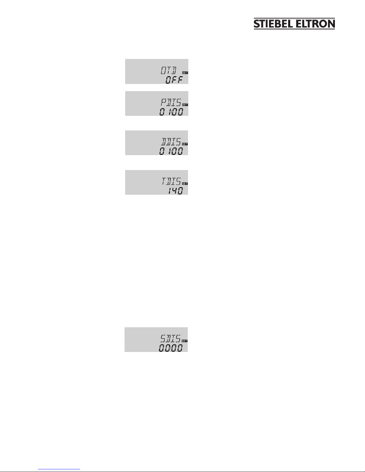
When a starting time for thermal disinfection with starting
delay is adjusted in SDIS, the thermal disinfection will be
delayed until that time, even after the CDIS has counted down
to 00:00. If CDIS ends, for example, at 12:00 o‘clock, and SDIS
has been set to 18:30, relay 2 will be operated with a delay of
6.5 hours at 18:30 instead of 12:00.
During the waiting time, SDIS is displayed with the adjusted
starting time (flashing).
If, during the waiting time, the temperature at S3 exceeds TDIS
for the adjusted heating period DDIS, thermal disinfection is
considered complete and a new monitoring period begins.
If the starting time is adjusted to 00:00 (factory setting), the
delay function is inactive.
Upon delivery, OTD is deactivated. The adjustment values PDIS,
TDIS, DDIS and SDIS are displayed after the option has been
activated. After the thermal disinfection function has been
completed, the values will be “hidden” and the monitoring
period will be displayed.
SDIS
Starting time
Adjustment range:
00:00 ... 24:00 (o‘clock)
Factory setting: 00:00
Thermal disinfection with starting delay
Option: Thermal disinfection of the upper DHW zone (OTD)
TDIS
Disinfection temperature
Adjustment range:
30 ... 200 °F
[0 ... 95 °C]
in steps of 2 °F [2 °C]
Factory setting:
140 °F [60 °C]
DDIS
Heating period
Adjustment range:
00:00 ... 23:59 (hh:mm)
Factory setting: 01:00
For thermal disinfection, the temperature in the upper DHW
tank zone has to be monitored. This protection is ensured
when, during the monitoring period (PDIS), the disinfection
temperature (TDIS) is continuously exceeded for the entire
heating period (DDIS). S3 is used as the reference sensor and
displayed as TSTT.
PDIS:
Monitoring period
Adjustment range:
0 ... 30:0 ... 24 h (dd:hh)
Factory setting: 01:00
This function is used for protecting the upper tank zone against
Legionella by activating the backup heating.
Reference sensor for the thermal disinfection is S3!
Î To activate the function, select “On” in the OTD channel.
OTD:
Thermal disinfection function
Adjustment range: ON / OFF
Factory setting: OFF
Due to the flexible control logic, the exact time of thermal
disinfection is not predictable. In order to set a fixed time
for the disinfection to be run, the starting delay SDIS must
be employed:
If OTD is activated, PDIS will start as soon as the temperature
at S3 falls below TDIS. The display channel CDIS appears,
counting backwards the remaining time of PDIS. If, during
the monitoring period, the temperature at S3 exceeds TDIS
continuously for the duration of DDIS, thermal disinfection is
considered complete and a new monitoring period begins.
If CDIS counts down to 00:00, relay 2 will be operated in order
to use the backup heating for thermal disinfection. CDIS will
then be replaced with a display channel DDIS showing the
adjusted heating period. DDIS will start counting down the
heating period as soon as TDIS is exceeded at S3. As long as
DDIS is active, the temperature at S3 will be displayed as TDIS
instead of TSTT.
If, during DDIS, the temperature at S3 exceeds TDIS by more
than 10°Ra [5K], relay 2 is switched off until the temperature
falls below TDIS+4°Ra [2K].
If, during DDIS, the temperature at S3 falls below TDIS, the
heating period will restart. DDIS can only be completed when
TDIS is exceeded without interruption.
16
System layout 4
S2
R1
S3
R2
S1
The controller calculates the temperature differences between
collector sensor S1 and tank sensors S2 and S3. If the
differences are larger than or identical to the adjusted switchon temperature differences (DT1O / DT2O), the solar pump will
be operated by relay 1, and the respective tank zone will be
loaded until the switch-off temperature differences (DT1F /
DT2F) or the maximum tank temperatures (S1MX / S2MX) are
S4 / TR
Arr 4
Display Channels
Channel Description Terminal Page
COL x Temperature collector S1 37
TSTB x Temperature tank 1 bottom S2 37
TSTT x Temperature tank 1 at the top S3 37
S4 x Temperature sensor 4 S4 37
TR x* Temperature return sensor S4 37
n % x Pump speed relay R1 38
hP1 x Operating hours R1 R1 38
hP2 x Operating hours R2 R2 38
kWh
x*
Heat quantity kWh - 38
MWh
x*
Heat quantity MWh - 38
TIME x Time - 34
reached. The priority logic causes priority loading of the upper
zone of the tank, if possible. The 3-way-valve will be operated
by relay 2 then.
Sensor S4 can optionally be connected for measurement
purposes.
If energy metering (OHQM) is activated, sensor S4 has to be
connected as return sensor.
 Loading...