

Page 1
SOM 10
Manual for the
specialized craftsman
Mounting
Electrical connection
Operation
Troubleshooting
Application examples
Simply the Best
*49014260*
49014260
Thank you for buying this product.
Read this manual carefully to get the best performance from this unit.
Please keep this manual carefully.
en-US/CA
Manual
Page 2
Safety advice
Please pay attention to the following safety advice
in order to avoid danger and damage to people and
property.
Instructions
Attention must be paid to the valid local standards,
regulations and directives!
Target group
These instructions are exclusively addressed to authorised skilled personnel.
Only qualied electricians should carry out electrical
works.
Initial installation must be effected by qualied per-
sonnel named by the manufacturer.
Disposal
• Dispose of the packaging in an environmentally
sound manner.
• Dispose of old appliances in an environmentally
sound manner. Upon request we will take back
your old appliances bought from us and guarantee
an environmentally sound disposal of the devices.
Information about the product
Proper usage
The solar controller is designed for use in solar thermal systems and heating systems in compliance with
the technical data specied in this manual.
Improper use excludes all liability claims.
Note
Strong electromagnetic elds can impair the
function of the controller.
Î Make sure the controller as well as the
system are not exposed to strong elec-
tromagnetic elds.
Subject to technical change. Errors excepted.
© 20120524_49014260_Stiebel_SOM_10.monus.indd
Description of symbols
WARNING!
Warnings are indicated with a warning triangle!
Î They contain information
on how to avoid the danger
described.
Signal words describe the danger that may occur,
when it is not avoided.
• WARNING means that injury, possibly life-threa-
tening injury, can occur.
• ATTENTION means that damage to the appli-
ance can occur.
Note
Notes are indicated with an information
symbol.
Î Arrows indicate instruction steps that should be
carried out.
2
Page 3

SOM 10
Contents
1 Overview .................................................... 4
1.1 Optional functions....................................................5
2 Installation ................................................. 5
2.1 Mounting ....................................................................5
2.2 Electrical connection ...............................................6
2.3 Data communication / Bus .....................................7
2.4 SD card slot ...............................................................8
3 Step-by-step parameterization ................ 8
4 Operation and function ............................ 9
4.1 Buttons .......................................................................9
4.2 Selecting menu points and adjusting values .......9
4.3 Menu structure .......................................................11
5 Initial commissioning .............................. 12
5.1 Basic systems and hydronic variants ..................14
5.2 Overview of relay and sensor allocation ..........15
6 Main menu ............................................... 30
7 Status ........................................................ 30
7.1 Solar...........................................................................30
7.2 Arrangement ...........................................................30
7.3 Heating ......................................................................30
7.4 Messages ...................................................................30
7.5 Meas. / Balance values ............................................31
7.6 Service ......................................................................31
8 Solar .......................................................... 31
8.1 Basic solar settings .................................................31
8.2 Solar optional functions ........................................34
8.3 Solar expert menu .................................................47
9 Arrangement ........................................... 47
9.1 Optional functions..................................................47
10 Heating ..................................................... 59
10.1 Demands ..................................................................60
10.2 Heating circuits .......................................................60
10.3 Optional functions..................................................64
11 HQM ......................................................... 67
12 Basic settings ........................................... 69
13 SD card ..................................................... 69
14 Manual mode ........................................... 71
15 User code ................................................. 72
16 In- / Outputs ............................................. 72
16.1 Modules ....................................................................72
16.2 Inputs .........................................................................73
16.3 Outputs ....................................................................74
16.4 PWM-Proles ..........................................................75
17 Troubleshooting ....................................... 76
18 Accessories .............................................. 80
18.1 Sensors and measuring instruments...................80
18.2 VBus
®
accessories ...................................................81
18.3 Interface adapters ...................................................81
19 Index ......................................................... 82
en
3
Page 4
1 Overview
• Extra large graphic display
• 14 relay outputs
• 12 temperature sensors
(system-dependent)
• 4 inputs for Grundfos Direct Sensors™
(2 × analog, 2 × digital)
• 4 PWM outputs for speed control of high-
efciencypumps
• Datalogging/rmwareupdatesviaSD
memory card
• 2 internal, weather-compensated heating
circuits
• Pre-programmed optional functions
• Drainback option
• Time-controlled thermostat function
en
• Heating period thermal disinfection
®
• VBus
• Energy-saving switch-mode power supply
Included:
1 x SOM 10
1 x accessory bag
3 x screw and wall plug
13 x strain relief and screw
Additionally enclosed in the full kit:
2 x FKP6 temperature sensor
4 x FRP6 temperature sensor
Note
The SD card is not included with the controller. For more information about accessories, see page 69
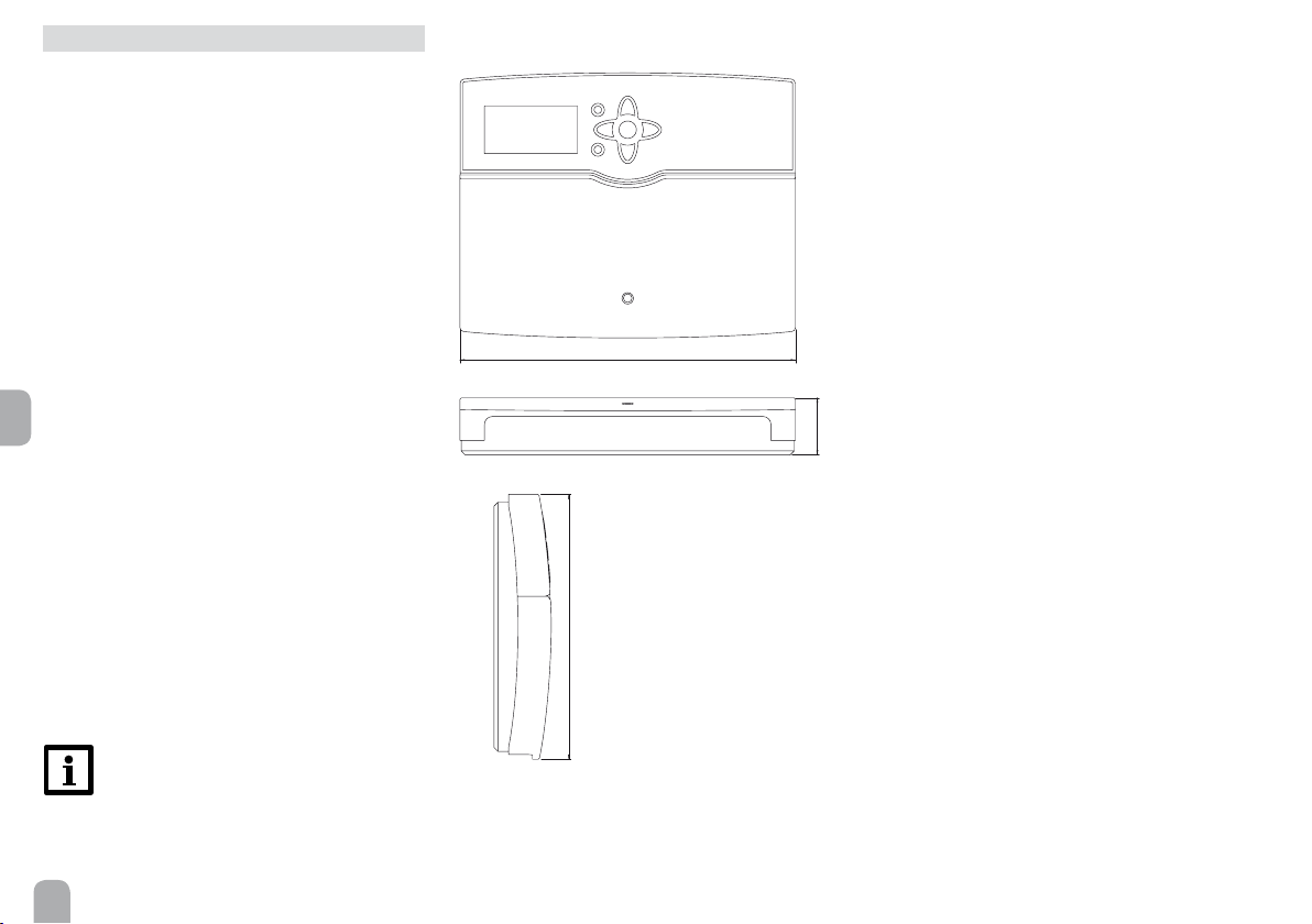
205
254
Technical data
Housing: plastic, PC-ABS and PMMA
Protection type: IP 20 / EN 60529
Protection class: I
Ambient temp.: 0...40 °C [32...104 °F]
Dimensions: 254 x 205 x 47 mm [10" x 8.1" x 1.9"]
Mounting: wall mounting, also suitable for mounting
into patch panels
Display: Full graphic display, control lamp (directional
pad) and background illumination
Operation: 7 push buttons at the front of the housing
Functions: System controller for solar and heating
systems. Functions such as: ∆T control, pump speed
control, energy metering, operating hours counter
for the solar pump, evacuated tube collector function,
thermostat function, vertical tank loading, priority
logic, drainback option, booster function, heat dump
function, thermal disinfection function, PWM pump
47
control, function control according to BAFA guidelines.
Inputs: 12 Pt1000, Pt500 or KTY temperature sensor
inputs (7 of them can optionally be used for RTA11-M
remote controls), 3 inputs for V40 owmeters, inputs
for 2 digital and 2 analog Grundfos Direct Sensors™,
1 input for a CS10 irradiation sensor
Outputs: 13 semiconductor relays, 1 dry contact relay, 4 PWM outputs
Interfaces: VBus
®
, SD card slot
Power supply: 100 ... 240 V~, 50 ... 60 Hz
Switching capacities per relay:
1 (1) A 100 ... 240 V~(semiconductor relay)
4 (2) A 100 ... 240 V~(dry contact relay)
Total switching capacity: 6.3 A
Standby power consumption: < 1W
Mode of operation: type 1.Y
Degree of pollution: 2
Rated impulse voltage: 2.5 kV
Contact termination: Y
44
Page 5
1.1 Optional functions
Solar
Bypass
CS Bypass
External heat exchanger
Evacuated tube collector
Target temperature
Antifreeze
Backup heating suppression
Parallel relay
Cooling mode
Drainback
Twin pump
Heat dump
Flow rate monitoring
Arrangement
Parallel relay
Mixer
Boiler loading
Error relay
Heat exchange
Solid fuel boiler
Circulation
Return preheating
Function block
Irradiation switch
Heating
Thermal Disinfection
DHW heating
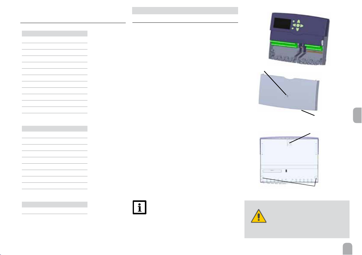
2 Installation
2.1 Mounting
The unit must only be located in dry interior rooms.
The controller must additionally be supplied from a
double pole switch with contact gap of at least 3 mm
[0.12“].
Please pay attention to separate routing of sensor
cables and power supply cables.
In order to mount the device to the wall, carry out
the following steps:
Î Unscrew the cross-head screw from the cover
and remove it along with the cover from the
housing
Î Mark the upper fastening point on the wall. Drill
and fasten the enclosed wall plug and screw leaving the head protruding
Î Hang the housing from the upper fastening point
and mark the lower fastening points (centres
223 mm [8.8“])
Î Insert lower wall plugs
Î Fasten the housing to the wall with the lower fas-
tening screws and tighten
Î Carry out the electrical wiring in accordance with
the terminal allocation, see chap. 2.2
Î Put the cover on the housing
Î Attach with the fastening screw
Note
Strong electromagnetic elds can impair the
function of the controller.
Make sure the controller as well as the sys-
tem are not exposed to strong electromag-
netic elds.
screw
WARNING!
cover
upper fastening point
lower fastening point
Electric shock!
Upon opening the housing, live parts
are exposed.
Î Always disconnect the con-
troller from power supply
before opening the housing!
en
5
Page 6
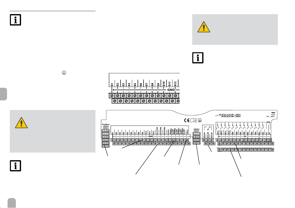
2.2 Electrical connection
Note
Connecting the device to the power supply
must always be the last step of the installation!
The controller is equipped with 14 relays in total to
which loads such as pumps, valves, etc. can be connected:
Relays 1 ... 13 are semiconductor relays, designed for
pump speed control:
Conductor R1 ... R13
Neutral conductor N (common terminal block)
Protective grounding conductor
(common termi-
nal block)
Relay 14 is a dry contact relay:
R14-A = normally open contact
en
R14-M = center contact
R14-R = normally closed contact
WARNING!
Electric shock!
Upon opening the housing, live
parts are exposed.
Î Always disconnect the con-
troller from power supply
before opening the housing!
Note
For more details about the initial commissioning procedure, see page 12.
Depending on the product version, power supply
cables and sensor cables are already connected to
the device. If that is not the case, please proceed as
follows:
Temperature sensors have to be connected to the
terminals S1 ... S12 and GND (either polarity).
WARNING!
ESD damage!
Electrostatic discharge can lead to
damage to electronic components!
Î Take care to discharge pro-
perly before touching the
inside of the device! To do
so, touch a grounded surface
such as a radiator or tap!
Note:
The pump speed must be set to 100 % when
auxiliary relays or valves are connected.
6
sensor terminals
input for analog
Grundfos Direct
Sensors™
sensor
grounding common terminal block
PWM (0-10 V)
terminals
VBus
potential-free
changeover relay
®
input for digital
Grundfos Direct Sensors™
neutral conductor
common terminal
block
protective grounding
conductor common
terminal block (PE)
Page 7
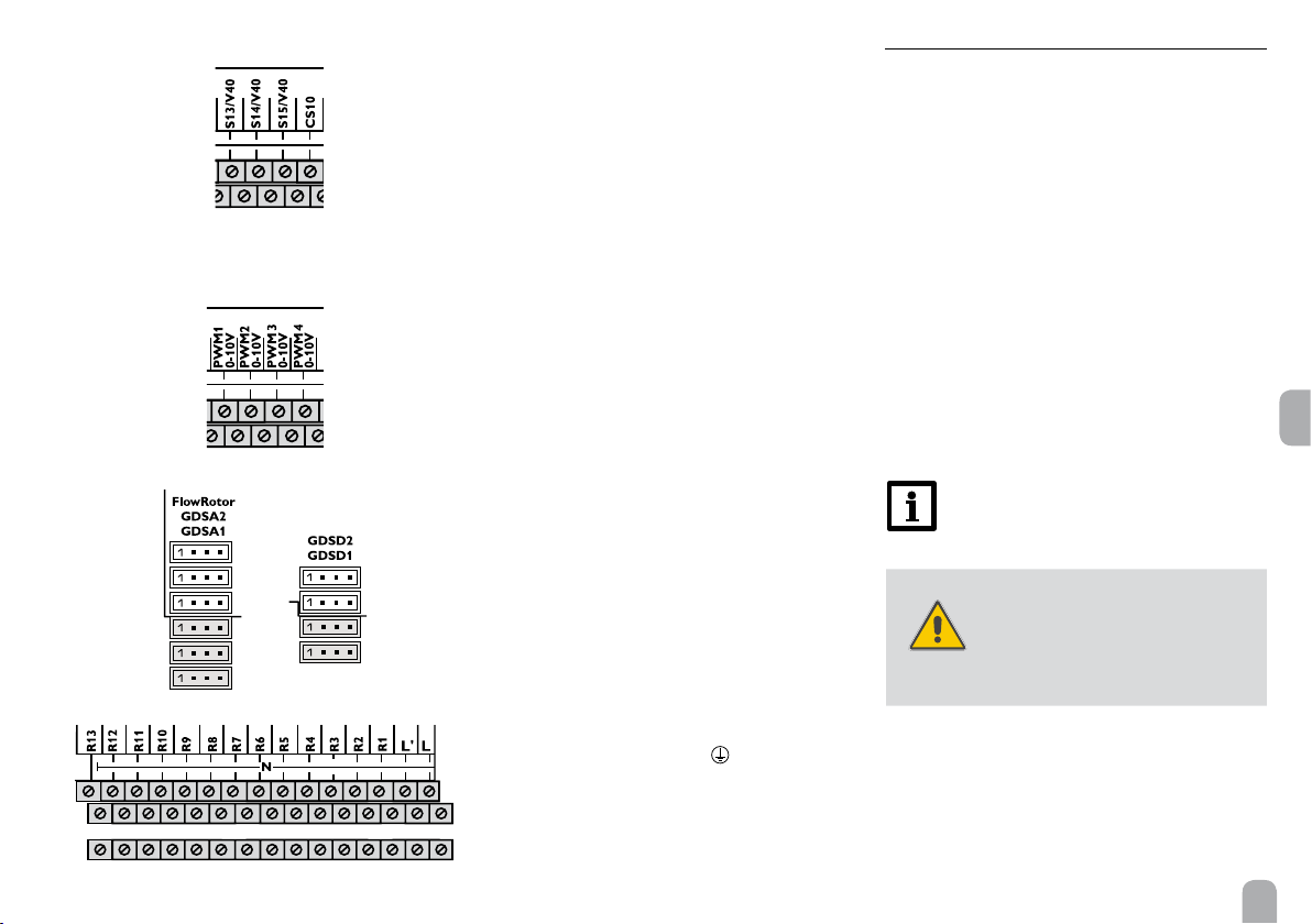
The terminals S13 to S15 can be used as either im-
pulse inputs for V40 owmeters or as inputs for FS08
ow switches
V40 owmeters can be connected to the terminals
S13 / V40 to S15 / V40 and GND (either polarity).
Connect the irradiation sensor CS10 to the termi-
nals CS10 and GND with correct polarity. To do so,
connect the cable marked GND to the GND common terminal block, the cable marked CS to the terminal marked CS10.
The terminals marked PWM are control outputs
for high-efciency pumps.
In the In-/Outputs menu, relays can be allocated to
the PWM outputs.
Connect the FlowRotor to the input marked FlowRotor.
Connect the analog Grundfos Direct Sensors™
to the inputs GDSA1 and GDSA2.
Connect the digital Grundfos Direct Sensors™
to the GDSD1 and GDSD2 inputs.
The controller is supplied with power via a power
supply cable. The power supply of the device must be
100 ... 240 V~ (50 ... 60Hz).
The power supply connection is at the terminals:
Neutral conductor N
Conductor L
Conductor L' (L' is not connected with the power
supply cable. L' is a fused contact permanently carrying voltage)
Protective grounging conductor
(common termi-
nal block)
2.3 Data communication / Bus
The controller is equipped with the VBus
®
for data
transfer with and energy supply to external modules.
The connection is carried out at the two terminals
marked VBus and GND (any polarity). One or more
VBus® modules can be connected via this data bus,
such as:
• GA3 Large Display module /
Smart Display SD3
• AM1 Alarm module
• DL2 Datalogger
• EM Extension module
Furthermore, the controller can be connected to a
PC via the VBus
®
/ USB or VBus® / LAN interface adapter (not included with the SOM 10). With the Service-
Center Software (RSC), measured values can be read,
processed and visualized. The software allows easier
paramatrisation and function control of the system.
Note:
For more information about accessories, see
page 80
WARNING!
Electric shock!
L‘ is a fused contact permanently
carrying voltage
Î Always disconnect the con-
troller from power supply
before opening the housing!
en
7
Page 8

2.4 SD card slot
The controller is equipped with
an SD card slot.
With an SD card, the following
functions can be carried out:
• Store measurement and
balance values onto the SD
card. After the transfer to
a computer, the values can
be opened and visualized, e. g. in a spreadsheet
programme.
• Prepare adjustments and parameterizations on a
computer and transfer them via the SD card.
• Store adjustments and parameterizations on the
SD card and, if necessary, retrieve them from there.
• Download rmware updates from the Internet and
install them on the controller.
en
A standard SD card is not included with the SOM 10.
For more information about using an SD card, see
page 69.
3 Step-by-step parameterization
The SOM 10 is a controller that offers a broad variety
of functions to the user. At the same time, the user has
a lot of freedom in congurating them. Therefore, to
set up a complex system, careful planning is required.
We recommend drawing a sketch of the system rst.
If planning, hydronic execution and electrical connection have all been carried out successfully, proceed as
follows:
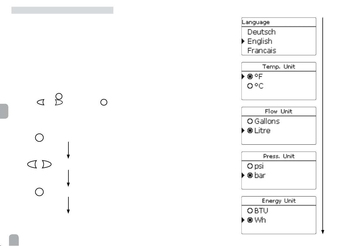
1. Running the commissioning menu
The commissioning menu is run after the rst connection and after every reset. It will request the following
basic adjustments:
• Menu language
• Temperature unit
• Volume unit
• Pressure unit
• Energy unit
• Time
• Date
• Solar system
• Hydronic variant
At the end of the commissioning menu, a safety en-
quiry follows. If the safety enquiry is conrmed, the
adjustments are saved.
For further information about the commissioning
menu see page 12.
2. Registering sensors
If owmeters, ow switches, Grundfos Direct Sensors™ and/or external extension modules are connected, these have to be registered in the In-/Outputs
menu.
For further information about the registration of modules and sensors see page 72.
3. Activating solar optional functions
The basic solar system has been adjusted during commissioning. Now, optional functions can be selected,
activated and adjusted.
Free relays can be allocated to optional functions
which require a relay. The controller always suggests
the numerically smallest free relay.
Sensors can be allocated to more than one function.
For further information about the solar optional func-
tions see page 34.
4. Activating optional arrangement functions
Now, optional functions for the non-solar part of the
arrangement can be selected, activated and adjusted.
Free relays can be allocated to optional functions
which require a relay. The controller always suggests
the numerically smallest free relay.
Sensors can be allocated any number of times without
impairing any other functions.
For further information about the optional arrangement functions see page 47.
5. Adjusting heating circuits and activating optional heating functions
Now, heating circuits can be activated and adjusted.
Internal heating circuits are only offered as long as at
least 3 relays are free.
For the heating part of the arrangement, optional
functions can be selected, activated and adjusted.
To heating circuits and optional functions which require one or more relays, the corresponding number
of free relays can be allocated. The controller always
suggests the numerically smallest free relay.
Sensors can be allocated any number of times without
impairing any other functions.
For further information about heating circuits and optional heating functions see page 59.
8
Page 9
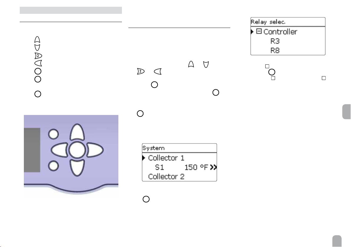
4 Operation and function
4.1 Buttons
The controller is energized via the 7 buttons next to
the display.They have the following functions:
1
Button
Button
Button
Button
Button
Button
Button
- scrolling upwards
3
- scrolling downwards
- increasing adjustment values
4
- reducing adjustment values
5
- conrming
- entering the status menu / chimney
6
sweeper mode (system-dependent)
7
- escape button for changing into the
previous menu
7
1
4
5
2
4.2 Selecting menu points and adjusting
values
During normal operation of the controller, the display
is in the main menu. If no button is pressed for a few
seconds, the display illumination goes out.
Press any key to reactivate the display illumination.
Î In order to scroll through a menu or to adjust a
1
value, press either buttons
4
and
Î To open a submenu or to conrm a value, press
button 5
Î To enter the status menu, press button
conrmed adjustments will not be saved
Î To switch one menu level upwards press button
7
– unconrmed adjustments will not be saved
If no button has been pressed within a couple of minutes, the adjustment is cancelled and the previous
value is retained.
and 3 or buttons
6
– un-
If the symbol
pressing button
already opened, a
+
is shown in front of a menu item,
5
will open a new submenu. If it is
is shown instead of the
–
.
+
en
6
3
If the symbol
button 5 will open a new submenu.
» is shown behind a menu item, pressing
9
Page 10
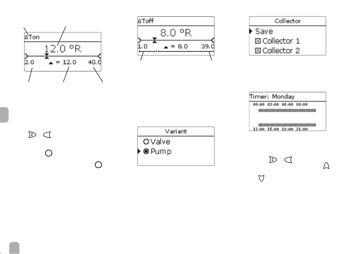
adjustment channel
adjusted value
(not yet conrmed)
current value savedminimum value maximum value
Values and adjustments can be changed in different
ways:
en
Numeric values can be adjusted by means of a slide
bar. The minimum value is indicated to the left, the maximum value to the right. The large number above the
slide bar indicates the current adjustment. By pressing
buttons or 4 the upper slide bar can be moved
to the left or to the right.
Only after the adjustment has been conrmed by
pressing button
5
will the number below the sli-
de bar indicate the new value. The new value will be
saved if it is conrmed by pressing button 5 again.
active area inactive area
When two values are locked against each other, they
will display a reduced adjustment range depending on
the adjustment of the respective other value.
In this case, the active area of the slide bar is shortened, the inactive area is indicated as a dotted line.
The indication of the minimum and maximum values
will adapt to the reduction.
If only one item of several can be selected, they will
be indicated with "radio buttons". When one item has
been selected, the radio button in front of it is lled.
If more than one item of several can be selected, they
will be indicated with checkboxes. When an item has
been selected, an x appears inside the checkbox.
The time frames for the timer can be adjusted in steps
of 15 minutes on a time line.
The cursor can be moved along the time line by
pressing buttons
or 4. The beginning of a time
frame can be determined by pressing button 1.
The end of a time frame can be determined by pres-
sing button
3
.
10
Page 11

4.3 Menu structure
Main menu
Status
Solar
Arrangement
Heating
HQM
Basic settings
SD card
Manual mode
User code
In- / Outputs
Expert
Solar
Basic settings
Optional functions
Expert
Arrangement
Optional functions
Heating
Demands
Heating circuits
Optional functions
Basic settings
Language
Auto DST
Date
Time
Temp. unit
Vol. unit
...
Basic settings
System
Collector
Store
Loading logic
Optional functions
Parallel relay
Mixer
Store loading
Error relay
...
The menu items and adjustment values selectable are variable depending on adjustments
already made. The gure only shows an exemplary excerpt of the complete menu in order to
visualize the menu structure.
Parallel relay
Relay
Reference relay
Overrun
Delay
Inverted
...
en
In- / Outputs
Modules
Inputs
Outputs
11
Page 12
5 Initial commissioning
When the hydronic system is lled and ready for operation, connect the controller to the power supply.
The controller runs an initialization phase in which
the directional pad ashes red.
When the controller is commissioned for the rst
time or when it is reset, it will run a commissioning
menu after the initialization phase. The commissioning
menu leads the user through the most important adjustment channels needed for operating the system.
Commissioning menu
The commissioning menu consists of the channels
described in the following. In order to make an adjustment, push button
sing buttons 4 and 2, then bush button 5 to
en
conrm. The next channel will appear on the display.
5
4
5
. Adjust the value by pres-
button navigation
adjustment mode
changing a value
2
1. Language:
Î Adjust the desired menu language.
2. Units:
Î Adjust the desired temperature unit.
Î Adjust the desired volume unit.
Î Adjust the desired pressure unit.
conrming a value
5
Î Adjust the desired energy unit.
next parameter appears auto-
12
matically
Page 13
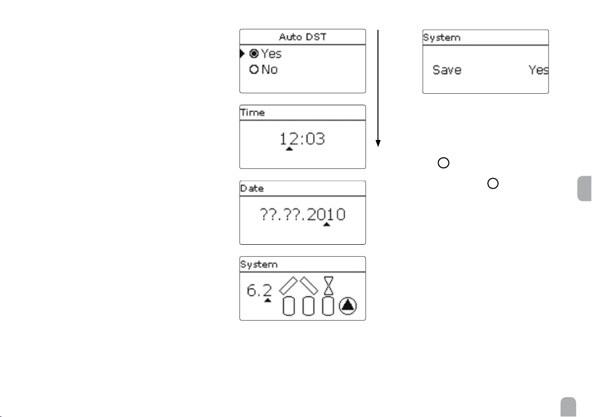
3. Daylight savings time adjustment:
Î Activate or deactivate the automatical daylight
savings time adjustment.
4. Time:
Î Adjust the clock time. First of all adjust the hours,
then the minutes.
5. Date:
Î Adjust the date. First of all adjust the year, then
the month and then the day.
6. Selection of the solar system:
Î Adjust the desired solar system (number of coll-
ectors and stores, hydronic variants).
7. Completing the commissioning menu:
After the system has been selected, a security enquiry
appears. If the enquiry is conrmed, the adjustments
will be saved.
Î In order to conrm the security enquiry, press
5
button
.
Î In order to reenter the commissioning menu
channels, press button
7
.
If the security enquiry has been conrmed, the controller is ready for operation and should enable an
optimum system operation.
All adjustments made during commissioning can, if
necessary, be changed later on in the basic settings
menu.
en
13
Page 14
5.1 Basic systems and hydronic variants
System
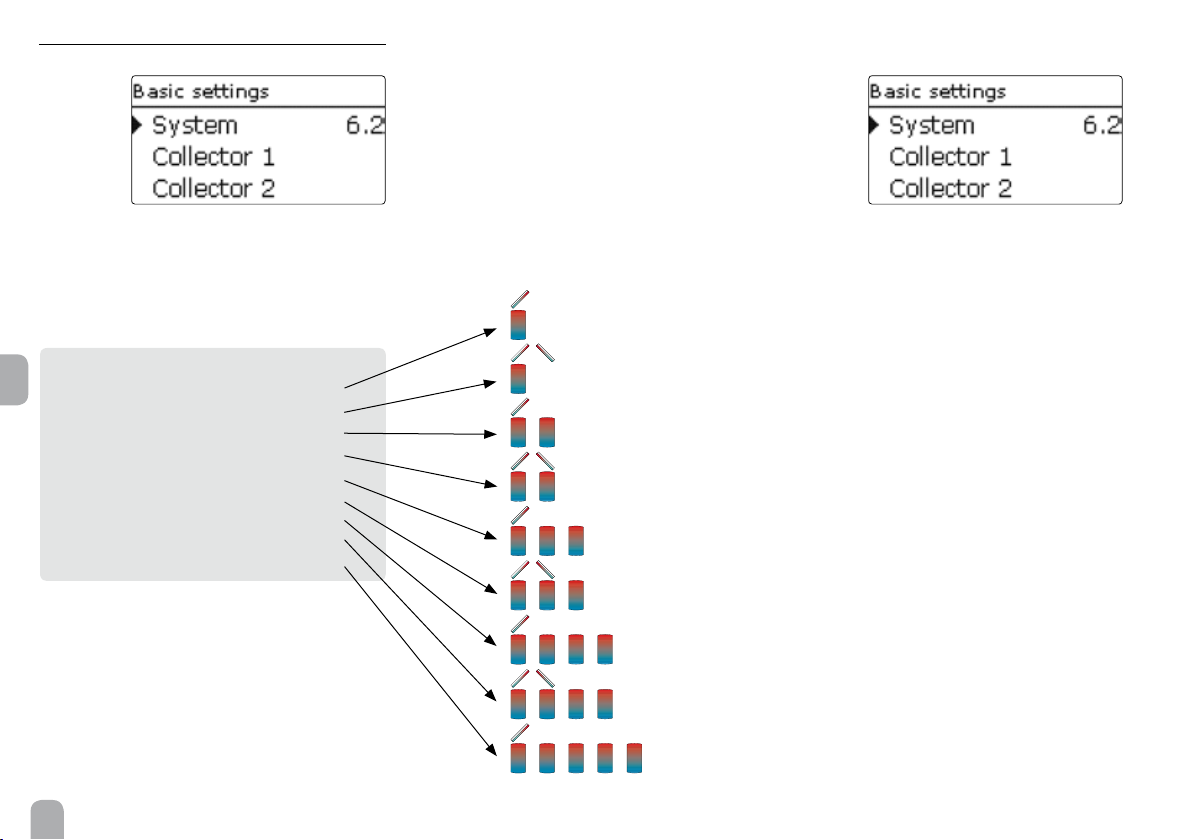
The controller is preprogrammed for 9 basic systems.
The selection depends on the number of heat sources
(collector elds) and heat sinks (stores, pool). Factory
setting is system 1.
System 0: no solar system
en
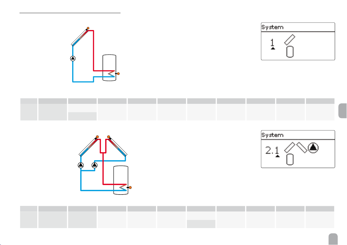
System 1: 1 collector eld - 1 store
System 2: east- / west collectors - 1 store
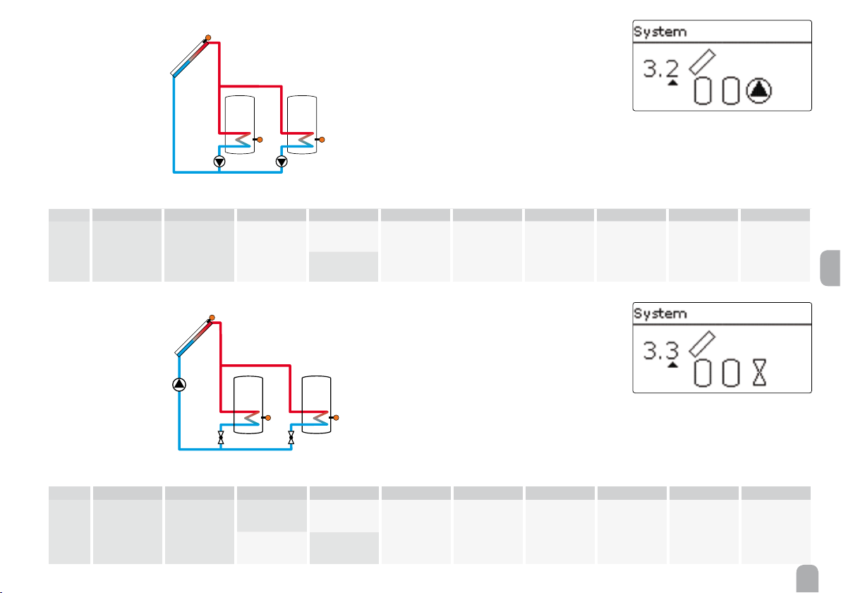
System 3: 1 collector eld - 2 stores
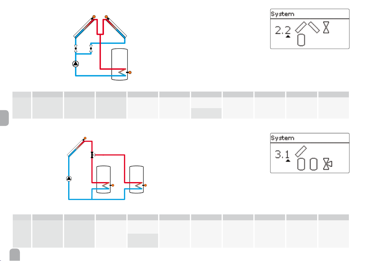
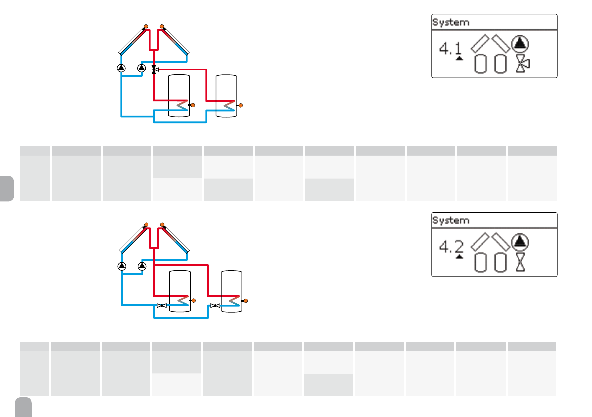
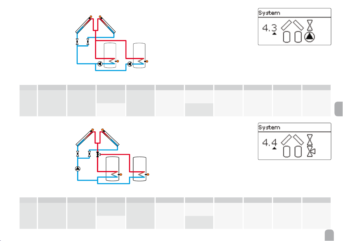
System 4: east- / west collectors - 2 stores
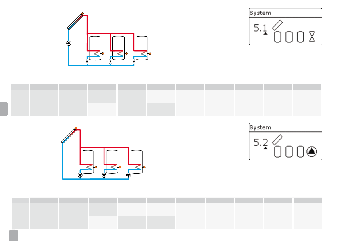
System 5: 1 collector eld - 3 stores
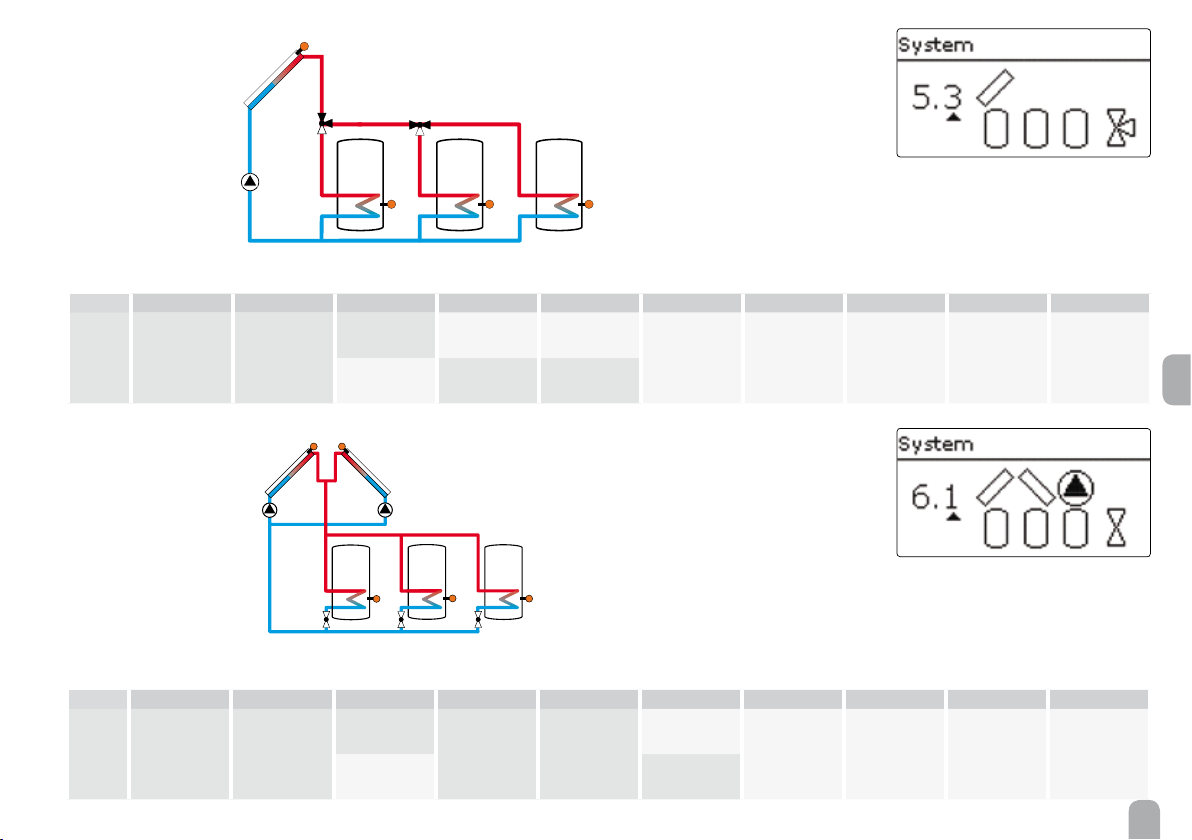
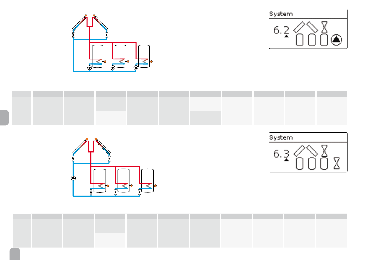
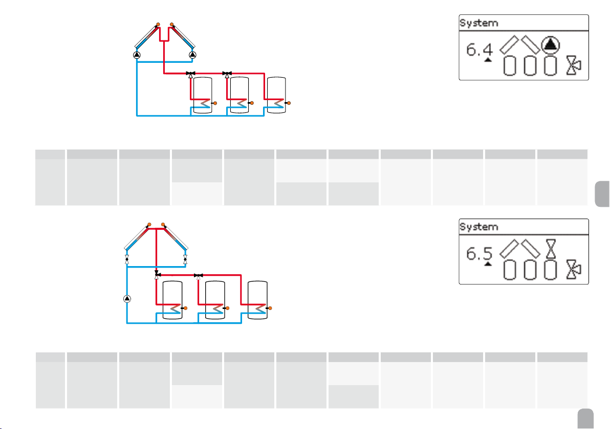
System 6: east- / west collectors - 3 stores
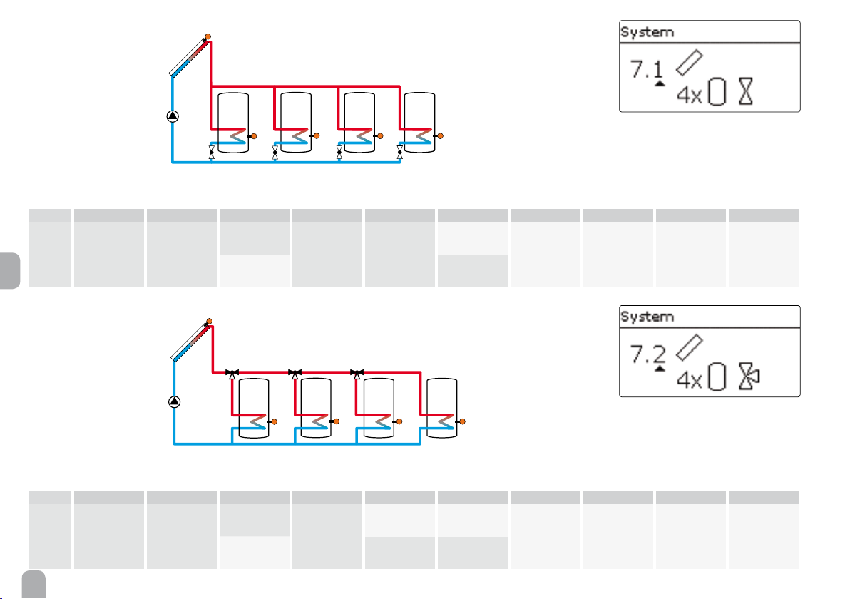
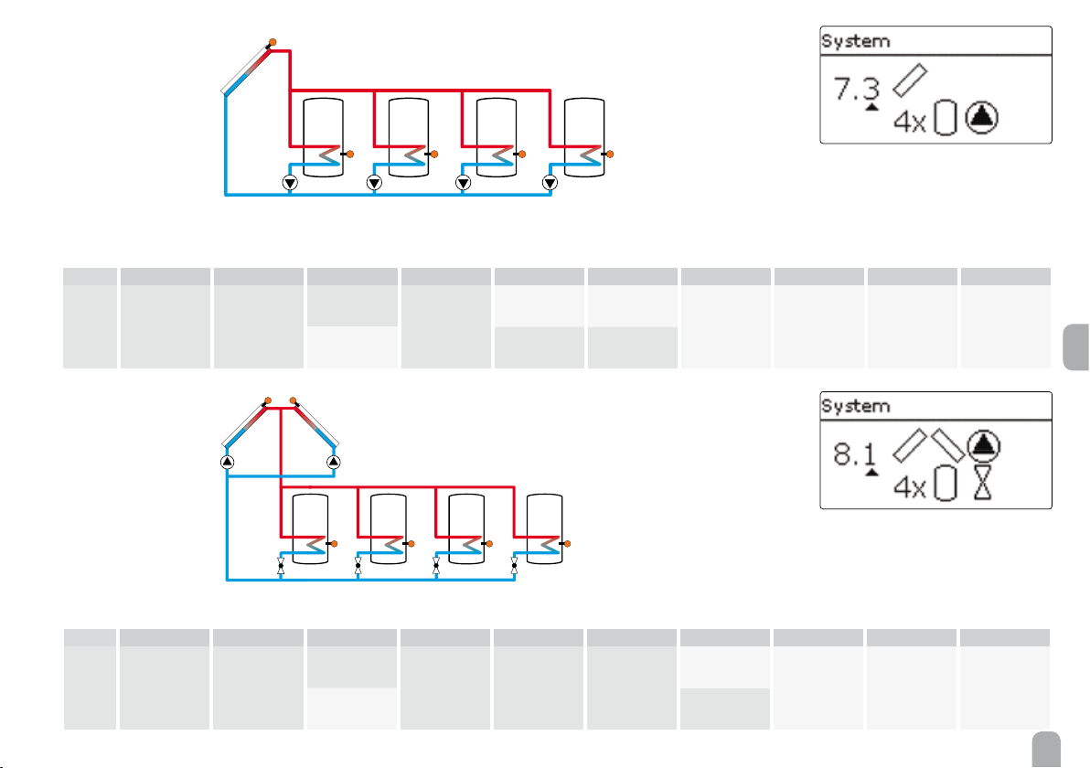
System 7: 1 collector eld - 4 stores
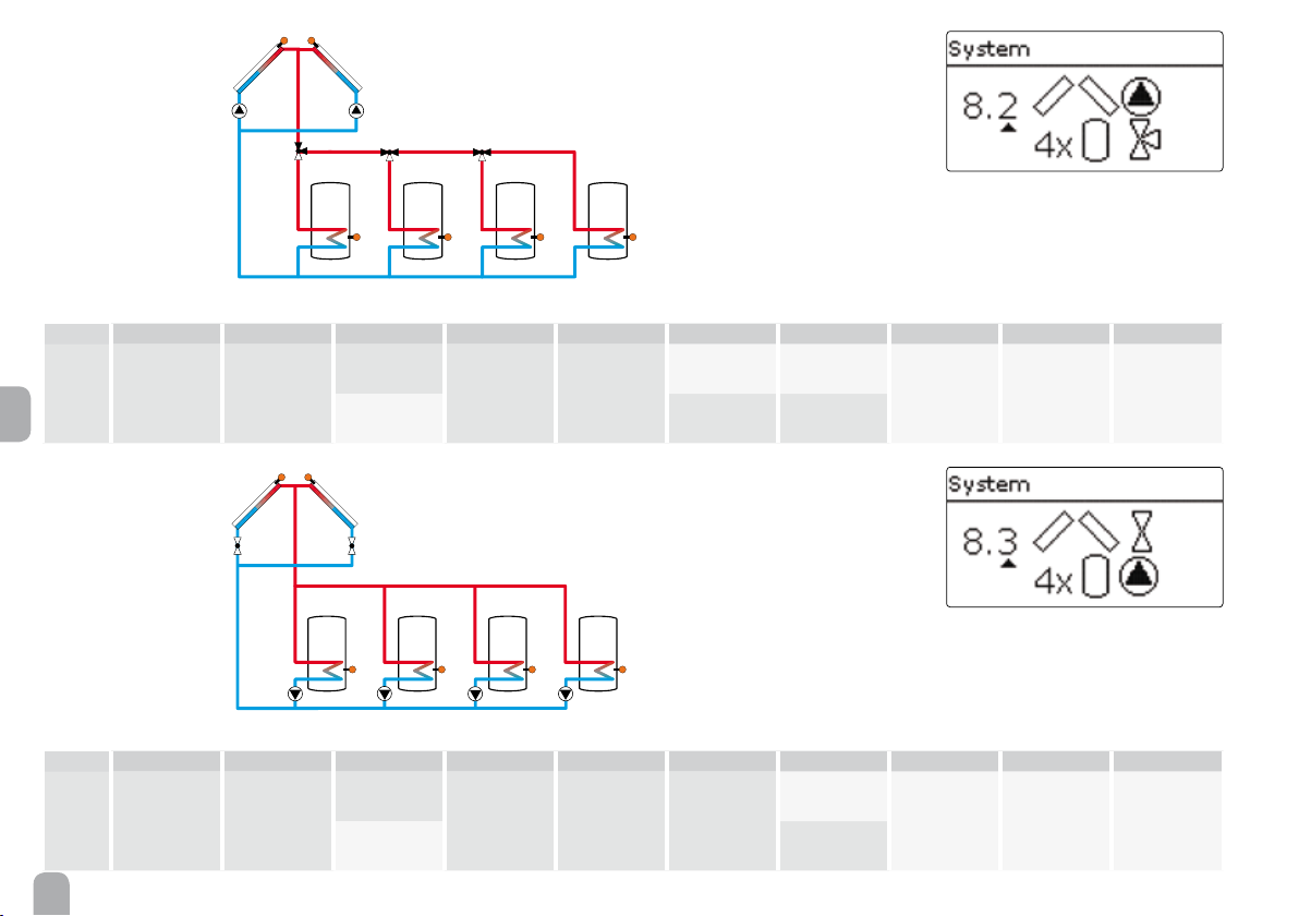
System 8: east- / west collectors - 4 stores
System 9: 1 collector eld - 5 stores
The selection of the basic solar system is one of the
most important adjustments and is thus requested already in the commissioning menu.
First, the basic system is adjusted by means of the
number of stores and collectors elds, then the hydronic variant.
The selected system is visualized by the corresponding number of store and collector symbols. The gure to the left shows system 6 which consists of 3
stores and 2 collector elds ("east- / west collectors").
Variant
The hydronic variant refers to the different actuators that are to be controlled. They are visualized on
the display by means of symbols, when the variant
is selected. The upper symbol indicates the actuator
belonging to the collector elds, the lower one the
actuators belonging to the stores.
The exemplary gure shows the display indicated
when system 6, variant 2 has been selected. In this
case, each collector eld has a 2-port valve, the stores
are loaded by means of pump logic.
For each variant, the controller allocates the corresponding relays and sensors. The allocations of the
most important combinations are shown in 5.2.
A solar system with vertical tank loading is implemented as a 2-store system
(store top = store 1; store bottom = store 2).
14
Page 15
5.2 Overview of relay and sensor allocation
System 1
S1
R1
S2
Relay / sensor allocation
1 2 3 4 5 6 7 8 9 10-14
Relay Solar pump Opt. function Opt. function Opt. function Opt. function Opt. function Opt. function Opt. function Opt. function Opt. function
Sensor Collector 1 Tank bottom Free Free Free Free Free Free Free Free
System 2 variant 1
R1 R2
S1 S6
S2
en
Relay / sensor allocation
1 2 3 4 5 6 7 8 9 10-14
Relay Pump coll. 1 Pump coll. 2 Opt. function Opt. function Opt. function Opt. function Opt. function Opt. function Opt. function Opt. function
Sensor Collector 1 Tank bottom Free Free Free Collector 2 Free Free Free Free
15
Page 16
System 2 variant 2
S1
S1 S6
R1 R2
R3
Relay / sensor allocation
1 2 3 4 5 6 7 8 9 10-14
Relay 2PV coll. 1 2PV coll. 2 Solar pump Opt. function Opt. function Opt. function Opt. function Opt. function Opt. function Opt. function
Sensor Collector 1 Tank bottom Free Free Free Collector 2 Free Free Free Free
en
System 3 variant 1
S2
R2
R1
S2
S4
Relay / sensor allocation
1 2 3 4 5 6 7 8 9 10-14
Relay Solar pump
Sensor
Collector Tank 1 bottom Free Tank 2 bottom Free Free Free Free Free Free
3PV
tank 2
Optional
function
Optional
function
Optional
function
Optional
function
Optional
function
Optional
function
Optional
function
Optional
function
16
Page 17
System 3 variant 2
S1
S1
S4S2
R1 R2
Relay / sensor allocation
1 2 3 4 5 6 7 8 9 10-14
Relay
Sensor Collector Tank 1 bottom Free Tank 2 bottom Free Free Free Free Free Free
System 3 variant 3
Solar pump
tank 1
Solar pump
tank 2
Optional
function
Optional
function
Optional
function
Optional
function
Optional
function
Optional
function
Optional
function
Optional
function
R1
S2 S4
Relay / sensor allocation
R2 R3
en
1 2 3 4 5 6 7 8 9 10-14
Relay Solar pump
Sensor Collector Tank 1 bottom Free Tank 2 bottom Free Free Free Free Free Free
2PV
tank 1
2PV
tank 2
Optional
function
Optional
function
Optional
function
Optional
function
Optional
function
Optional
function
Optional
function
17
Page 18
System 4 variant 1
S1 S6
S1 S6
Relay / sensor allocation
Relay
en
Sensor
System 4 variant 2
Relay / sensor allocation
Relay
Pump coll. 1 Pump coll. 2
Collector 1 Tank 1 bottom Free Tank 2 bottom Free Collector 2 Free Free Free Free
Pump coll. 1 Pump coll. 2
R1
R3
R2
S2 S4
1 2 3 4 5 6 7 8 9 10-14
3PV
tank 2
Optional
function
Optional
function
Optional
function
Optional
function
Optional
function
Optional
function
Optional
function
R1
R2
S4S2
R3 R4
1 2 3 4 5 6 7 8 9 10-14
2PV
tank 1
2PV
tank 2
Optional
function
Optional
function
Optional
function
Optional
function
Optional
function
Optional
function
Sensor
18
Collector 1 Tank 1 bottom Free Tank 2 bottom Free Collector 2 Free Free Free Free
Page 19
System 4 variant 3
R1
R2
S1 S6
R3
R4
S4S2
R1
R2
S2 S4
R4
S1 S6
R3
Relay / sensor allocation
1 2 3 4 5 6 7 8 9 10-14
Relay
2PV coll. 1 2PV coll. 2
Solar pump
tank 1
Solar pump
tank 2
Optional
function
Optional
function
Optional
function
Optional
function
Optional
function
Optional
function
Sensor
System 4 variant 4
Relay / sensor allocation
Relay
Sensor
Collector 1 Tank 1 bottom Free Tank 2 bottom Free Collector 2 Free Free Free Free
2PV coll. 1 2PV coll. 2 Solar pump
Collector 1 Tank 1 bottom Free Tank 2 bottom Free Collector 2 Free Free Free Free
1 2 3 4 5 6 7 8 9 10-14
3PV
tank 1
Optional
function
Optional
function
Optional
function
Optional
function
Optional
function
Optional
function
en
19
Page 20
System 5 variant 1
S1
Relay / sensor allocation
Relay
en
Sensor
Solar pump
Collector 1 Tank 1 bottom Free Tank 2 bottom Tank 3 bottom Free Free Free Free Free
R1
S2 S4 S5
R2 R3 R4
1 2 3 4 5 6 7 8 9 10-14
2PV
tank 1
2PV
tank 2
2PV
tank 3
Optional
function
Optional
function
Optional
function
Optional
function
Optional
function
Optional
function
System 5 variant 2
Relay / sensor allocation
1 2 3 4 5 6 7 8 9 10-14
Relay
Sensor
20
Solar pump
tank 1
Collector 1 Tank 1 bottom Free Tank 2 bottom Tank 3 bottom Free Free Free Free Free
S1
R1 R2 R3
Solar pump
tank 2
Solar pump
tank 3
Optional
function
S5S4S2
Optional
function
Optional
function
Optional
function
Optional
function
Optional
function
Optional
function
Page 21
System 5 variant 3
S1
S6S1
Relay / sensor allocation
1 2 3 4 5 6 7 8 9 10-14
Relay
Sensor
System 6 variant 1
Solar pump
Collector 1 Tank 1 bottom Free Tank 2 bottom Tank 3 bottom Free Free Free Free Free
Relay / sensor allocation
R2
R1
3PV
tank 1
R1 R2
3PV
tank 2
S2 S4 S5
R3
S2 S4 S5
Optional
function
R5R4R3
Optional
function
Optional
function
Optional
function
Optional
function
Optional
function
Optional
function
en
Relay
Sensor
1 2 3 4 5 6 7 8 9 10-14
Pump coll. 1 Pump coll. 2 2PV tank 1 2PV tank 2 2PV tank 3
Collector 1 Tank 1 bottom Free Tank 2 bottom Tank 3 bottom Collector 2 Free Free Free Free
Optional
function
Optional
function
Optional
function
Optional
function
Optional
function
21
Page 22
System 6 variant 2
S1 S6
S2 S4 S5
R1 R2 R3
R5R4
S1 S6
Relay / sensor allocation
Relay
en
Sensor
System 6 variant 3
Relay / sensor allocation
Solar pump
tank 1
Collector 1 Tank 1 bottom Free Tank 2 bottom Tank 3 bottom Collector 2 Free Free Free Free
Relay
2PV coll. 1 2PV coll. 2 Solar pump
1 2 3 4 5 6 7 8 9 10-14
Solar pump
tank 2
Solar pump
tank 3
2PV coll. 1 2PV coll. 2
Optional
function
Optional
function
Optional
function
Optional
function
Optional
function
R1 R2
R3
S2 S4 S5
R4 R5 R6
1 2 3 4 5 6 7 8 9 10-14
2PV
tank 1
2PV
tank 2
2PV
tank 3
Optional
function
Optional
function
Optional
function
Optional
function
Sensor
22
Collector 1 Tank 1 bottom Free Tank 2 bottom Tank 3 bottom Collector 2 Free Free Free Free
Page 23
System 6 variant 4
S1
S6
S1 S6
Relay / sensor allocation
Relay
Sensor
System 6 variant 5
Relay / sensor allocation
Relay
R1
R2
R3 R4
S2 S4 S5
1 2 3 4 5 6 7 8 9 10-14
Pump coll. 1 Pump coll. 2 3PV tank 1 3PV tank 2
Optional
function
Optional
function
Optional
function
Optional
function
Optional
function
Optional
function
Collector 1 Tank 1 bottom Free Tank 2 bottom Tank 3 bottom Collector 2 Free Free Free Free
R1
R3
R4
R2
R5
S2 S4 S5
1 2 3 4 5 6 7 8 9 10-14
2PV coll. 1 2PV coll. 2 Solar pump
3PV
Tank 1
3PV
Tank 2
Optional
function
Optional
function
Optional
function
Optional
function
Optional
function
en
Sensor
Collector 1 Tank 1 bottom Free Tank 2 bottom Tank 3 bottom Collector 2 Free Free Free Free
23
Page 24
System 7 variant 1
S1
S1
Relay / sensor allocation
Relay
en
Sensor
System 7 variant 2
Solar pump
Collector 1 Tank 1 bottom Free Tank 2 bottom Tank 3 bottom Tank 4 bottom Free Free Free Free
Relay / sensor allocation
Relay
Solar pump
R1
S2 S4 S5
S6
R2 R3 R4 R5
1 2 3 4 5 6 7 8 9 10-14
2PV
tank 1
2PV
tank 2
2PV
tank 3
2PV
tank 4
Optional
function
Optional
function
Optional
function
Optional
function
Optional
function
R2 R3 R4
R1
S2 S4 S5
1 2 3 4 5 6 7 8 9 10-14
3PV
tank 1
3PV
tank 2
3PV
tank 3
Optional
function
S6
Optional
function
Optional
function
Optional
function
Optional
function
Optional
function
Sensor
24
Collector 1 Tank 1 bottom Free Tank 2 bottom Tank 3 bottom Tank 4 bottom Free Free Free Free
Page 25
System 7 variant 3
Relay / sensor allocation
1 2 3 4 5 6 7 8 9 10-14
Relay
Solar pump
tank 1
S1
S2 S4 S5 S6
R1 R2 R3 R4
Solar pump
tank 2
Solar pump
tank 3
Solar pump
tank 4
Optional
function
Optional
function
Optional
function
Optional
function
Optional
function
Optional
function
Sensor
Collector 1 Tank 1 bottom Free Tank 2 bottom Tank 3 bottom Tank 4 bottom Free Free Free Free
System 8 variant 1
Relay / sensor allocation
1 2 3 4 5 6 7 8 9 10-14
Relay
Sensor
Pump coll. 1 Pump coll. 2
Collector 1 Tank 1 bottom Free Tank 2 bottom Tank 3 bottom Collector 2 Tank 4 bottom Free Free Free
R1
en
S1
R3
S6
R2
S2 S4 S5 S7
R4
2PV
tank 1
R5
2PV
tank 2
R6
2PV
tank 3
2PV
tank 4
Optional
function
Optional
function
Optional
function
Optional
function
25
Page 26
System 8 variant 2
S1
S6
Relay / sensor allocation
Relay
Pump coll. 1 Pump coll. 2
en
Sensor
Collector 1 Tank 1 bottom Free Tank 2 bottom Tank 3 bottom Collector 2 Tank 4 bottom Free Free Free
System 8 variant 3
Relay / sensor allocation
Relay
Solar pump
tank 1
R1
R2
R3
R4
S2 S4 S5 S7
R5
1 2 3 4 5 6 7 8 9 10-14
3PV
tank 1
S1
R5
S6
R6
S2 S4 S5 S7
R1
R2
3PV
tank 2
R3
3PV
tank 3
R4
Optional
function
Optional
function
Optional
function
Optional
function
Optional
function
1 2 3 4 5 6 7 8 9 10-14
Solar pump
tank 2
Solar pump
tank 3
Solar pump
tank 4
2PV coll. 1 2PV coll. 2
Optional
function
Optional
function
Optional
function
Optional
function
Sensor
26
Collector 1 Tank 1 bottom Free Tank 2 bottom Tank 3 bottom Collector 2 Tank 4 bottom Free Free Free
Page 27

System 8 variant 4
S1
S6
Relay / sensor allocation
1 2 3 4 5 6 7 8 9 10-14
Relay
Sensor
2PV coll. 1 2PV coll. 2 Solar pump
Collector 1 Tank 1 bottom Free Tank 2 bottom Tank 3 bottom Collector 2 Tank 4 bottom Free Free Free
System 8 variant 5
Relay / sensor allocation
1 2 3 4 5 6 7 8 9 10-14
Relay
2PV coll. 1 2PV coll. 2 Solar pump
R1
R3
R2
S2 S4 S5 S7
R4
R5
R6
tank 1
2PV
R7
2PV
tank 2
2PV
tank 3
2PV
tank 4
Optional
function
Optional
function
Optional
function
en
S1
R1
R3
S6
R2
R4
R5
S2 S4 S5 S7
R6
3PV
tank 1
3PV
tank 2
3PV
tank 3
Optional
function
Optional
function
Optional
function
Optional
function
Sensor
Collector 1 Tank 1 bottom Free Tank 2 bottom Tank 3 bottom Collector 2 Tank 4 bottom Free Free Free
27
Page 28

System 9 variant 1
S1
Relay / sensor allocation
Relay
en
Sensor
System 9 variant 2
Solar pump
Collector 1 Tank 1 bottom Free Tank 2 bottom Tank 3 bottom Tank 4 bottom Tank 5 bottom Free Free Free
Relay / sensor allocation
Relay
Solar pump
R1
S2 S4 S5 S6 S7
R2
1 2 3 4 5 6 7 8 9 10-14
2PV
tank 1
R3 R4 R5 R6
2PV
tank 2
2PV
tank 3
2PV
tank 4
2PV
tank 5
Optional
function
Optional
function
Optional
function
Optional
function
S1
R2
R3
R4
R5
R1
S2 S4 S5 S6 S7
1 2 3 4 5 6 7 8 9 10-14
3PV
tank 1
3PV
tank 2
3PV
tank 3
3PV
tank 4
Optional
function
Optional
function
Optional
function
Optional
function
Optional
function
Sensor
28
Collector 1 Tank 1 bottom Free Tank 2 bottom Tank 3 bottom Tank 4 bottom Tank 5 bottom Free Free Free
Page 29

System 9 variant 3
S1
Relay / sensor allocation
1 2 3 4 5 6 7 8 9 10-14
Relay
Solar pump
tank 1
S2 S4 S5 S6 S7
R1 R2 R3 R4 R5
Solar pump
tank 2
Solar pump
tank 3
Solar pump
tank 4
Solar pump
tank 5
Optional
function
Optional
function
Optional
function
Optional
function
Optional
function
Sensor
Collector 1 Tank 1 bottom Free Tank 2 bottom Tank 3 bottom Tank 4 bottom Tank 5 bottom Free Free Free
en
29
Page 30

6 Main menu
7 Status
7.3 Heating
During normal operation, the display of the controller
shows the main menu. From here, the different menu
areas can be selected.
The following menus are available:
• Status
• Solar
• Arrangement
• Heating
en
• HQM
• Basic settings
• SD card
• Manual mode
• User code
• In- / Outputs
• Expert
Î Select the menu area by pressing buttons
Î Press button 5 in order to enter the selected
menu
Note
When no button is pressed for 1 minute, the
display illumination stops. After 3 more minutes, the controller switches into the Status
menu.
Î In order to access the main menu, press
7
button
!
30
1
and
In the Status menu, the status messages for every
menu area can be found.
7.1 Solar
In the Status / Solar menu, the status of the solar
system, the solar loading and the selected optional
functions are indicated.
7.2 Arrangement
3
In the Status / Arrangement menu, the status of
the selected optional functions is indicated.
In the Status / Heating menu, the status of the demands and heating circuits activated as well as of the
selected optional functions is indicated.
7.4 Messages
In the Status / Messages menu, error and warning messages which have not been acknowledged are indicated.
During normal operation, the message Everything OK
is indicated.
A line break or short circuit in a sensor line is indicated
as !Sensor fault. A precise error code can be found in
the Status / Meas.- / Balance values menu.
If the optional function Flow rate monitoring is activated
and has detected an error, the message !Flow r. monit.
is indicated.
All messages will additionally be displayed in the corresponding menus. In order to acknowledge an error
message, the corresponding menu has to be entered.
If, for example, the message !Flow r. monit. appears,
it will also be displayed in the Solar / Optional func-
tions / Flow rate monitoring. In that menu, the message can be acknowledged.
Page 31

7.5 Meas. / Balance values
8 Solar
If, for example, S1 is selected, a submenu indicating the
minimum and maximum values will open.
When the item Chart is selected, a progression chart
appears.
In the Status / Meas. / Balance values menu, all cur-
rent measurement values as well as a range of balance
values are displayed. Some of the menu items can be
selected in order to enter a submenu.
Additionally, all optional functions selected, the operating hours counter as well as activated heat quantity
measurements are displayed.
If, for example, Solar / System is selected, a submenu
with the sensors and relays allocated to the solar system opens. In the submenu, the current temperatures
and the current pump speed are displayed.
When a line with a measurement value is selected,
another submenu will open.
The progression chart shows the development of the
temperature at the corresponding sensor over the
last 24 hours. Press buttons
back and forth between a chart of the current day and
one of the day before.
7.6 Service
In the Status / Service menu, each sensor and relay is indicated with the component or function it has
been allocated to. For free sensors and relays, Free
is indicated.
and 4 to switch
In this menu, all adjustments for the solar part of the
arrangement can be made. The Solar menu consists of
the following submenus:
• Basic settings
• Optional functions
• Expert
8.1 Basic solar settings
In the Basic settings menu, all basic settings for the
solar part of the arrangement can be adjusted.
In this menu, the hydronic system, which is the basis
for the arrangement, can be adjusted. The setting is
divided into systems and variants.
Both system and variant have usually been adjusted
during commissioning. If the setting is changed later
on, all adjustments for the solar part of the arrangement are set back to their factory settings.
If the change causes the new solar system to require a relay that has been allocated to an arrangement
function before, all adjustments made in the non-solar
part will be set back to their factory settings as well.
en
31
Page 32

First of all, the basic solar system can be selected ac-
cording to the number of stores and collector elds
in use. The corresponding numbers are indicated on
the display.
The exemplary gure shows system 6 with its 3 stores
and 2 collector elds (east- / west collectors).
en
The following items in the Solar / Basic settings menu
will adjust to the system selected.
Collector (1/2)
In systems with 2 collector elds, 2 seperate menu
items (Collector 1 and Collector 2) are displayed
instead of Collector.
For each collector eld, a collector minimum limitation and a collector emergency shutdown temperature
can be adjusted.
When the basic system has been selected and conrmed, the hydronic variant can be selected. The variant is visualized on the display by means of pump and
valve symbols. The exemplary gure shows variant 2
of system 6 with a 2-port valve and a pump. For an
overview of the basic systems and their variants see
chap. 5.2 on page 15.
The controller supports up to 2 collector elds and
up to 5 solar stores (with 2 collector elds only up to
4 solar stores).
32
Solar / Basic settings / Collector (1/2)
Adjustment channel Description Adjustment range / selection Factory setting
Colmin. Minimum collector limitation Yes, No Ye s
Colmin. Minimum collector temperature 10 ... 90 °C [50 ... 194 °F] 10 °C [50 °F]
Colem. Collector emergency shutdown Yes, No Yes
Colem.
Collector emergency
temperature
80 ... 200 °C [176 ... 392 °F] 130 °C [266 °F]
Page 33

Store (1 / 2 / 3 / 4 / 5)
In systems with 2 or more stores, the corresponding number of seperate menu items (Store 1 to
Store 5) is displayed instead of Store.
For each store, an individual ∆T control, a set and a
maximum temperature, the priority, a hysteresis, a rise
value, a minimum runtime and a minimum pump speed
can be adjusted.
In multi-store-systems with differing Store set / Maximum store temperatures, all stores are loaded up
to their Stset temperatures rst (according to their
priority and the store sequence control). Only when
all stores have exceeded Stset will they be loaded
up to their Stmax temperatures, again according to
their priority and the store sequence control.
Solar / Basic settings / Store (1 / 2 / 3 / 4 / 5)
Adjustment channel Description Adjustment range / selection Factory setting
∆To n
∆Toff
∆Tset
Stset Store set temperature 4 ... 95 °C [40 ... 204 °F] 45 °C [114 °F]
Stmax Maximum store temperature 4 ... 95 °C [40 ... 204 °F] 60 °C [140 °F]
Priority Priority 1
HysSt
Rise Rise 1.0 ... 20.0 K [2.0 ... 40.0°Ra] 2.0 K [4.0 °Ra]
tmin Minimum runtime 0 ... 300 180
Min speed. Minimum speed 30 ... 100 % 30 %
Deactivated Blocked for solar loading Yes, No No
Switch-on temperature difference 1.0 ... 20.0 K [2.0 ... 40.0°Ra] 6.0 K [12.0 °Ra]
Switch-off temperature difference 0.5 ... 19.5 K [1.0 ... 39.0°Ra] 4.0 K [8.0 °Ra]
Set temperature 1.5 ... 30.0 K [1.5 ... 60.0°Ra] 10.0 K [20.0 °Ra]
1 ... 5
(system-dependent)
Hysteresis maximum store
temperature
0.1 ... 10.0 K [0.2 ... 20.0°Ra] 2.0 K [4.0 °Ra]
en
33
Page 34

Loading logic
In systems with 2 or more stores, loading logic adjustments can be made in this menu.
In systems 1 and 2, only the menu item Pump delay
will be available.
If the priority store cannot be loaded, the subordinate
store next in priority is checked. If useful heat can
en
be added, it will be loaded for the circulation time
(Circ. – factory setting 15 min.) After this, the loading
Solar / Basic settings / Loading logic
process stops and the controller monitors the increase in collector temperature during the loading break
time Load. break. If it increases by 2 K [4° Ra], the
break time timer starts again to allow the collector
to gain more heat. If the collector temperature does
not increase sufciently, the subordinate store will be
loaded again for the Circ. time as before.
As soon as the switch-on condition of the priority
store is fullled, it will be loaded. If the switch-on
condition of the priority store is not fullled, loading
of the second store will be continued. If the priority
store reaches its maximum temperature, sequence
controlled loading will not be carried out.
If store sequence control is active and the system
switches to load the priority store, the parameter
Load. break also acts as a stabilization timer, during
which the switch-off condition is ignored while the
system operation stabilizes.
8.2 Solar optional functions
In this menu, additional functions can be selected and
adjusted for the solar part of the arrangement.
By selecting Add new function..., different pre-programmed functions can be selected. The optional functions are available as long as free relays are available.
Adjustment channel Description Adjustment range / selection Factory setting
Load. break Loading break time 1 ... 5 2
Circ. Circulation time 1 ... 60 15
Break speed Pause speed Yes, No No
Speed Pause speed 30 ... 100 % 30 %
Pump delay Pump delay Yes, No No
Delay Delay time 5 ... 600 15
34
When a function is selected, a submenu opens in
which all adjustments required can be made.
With this menu item, a relay and, if necessary, certain
system components can be allocated to the function.
Page 35

Relay selec.ControllerOpt. functionsAdd new
function...Status / Service
At the end of each optional function submenu, the
menu items Funct. and Delete function are available.
With the menu item Funct., an optional function already selected can be temporarily deactivated or reactivated respectively. All adjustments remain stored,
the allocated relays remain occupied and cannot be
allocated to another function.
If the menu item Delete function is conrmed by
pressing button 5, a security enquiry appears. The
setting can be changed between Yes and No by pres-
sing buttons and 4. If Ye s has been selected
5
and conrmed by pressing button
, the function
is deleted and available under Add new function...
again. The corresponding relays are available again.
Bypass
In order to prevent energy from being extracted from
the store when starting store loading, this function
makes sure that the cold uid in the pipes is diverted
past the store via a bypass (valve or pump). Once the
pipe is warm enough, the store can be loaded. The
switch-on conditions can be adjusted individually.
en
35
Page 36

Variant pump:
Relay
en
Exemplary schematics for the bypass variants
Solar / Opt. functions / Add new function... / Bypass
Adjustment channel Description Adjustment range / selection Factory setting
Collector Collector eld system dependent system dependent
Relay Bypass relay system dependent system dependent
Variant Variant (pump or valve logic) pump, valve pump
Sensor Bypass sensor system dependent system dependent
∆To n
∆Toff
Funct. Activation / Deactivation Activ., Deactivated Activ.
Bypass sensor
Switch-on temperature difference 1.0 ... 20.0 K [2.0 ... 40.0 °Ra] 6.0 K [12.0 °Ra]
Switch-off temperature difference 0.5 ... 19.5 K [1.0 ... 39.0 °Ra] 4.0 K [8.0 °Ra]
Variant valve:
Bypass sensor
Relay
Depending on whether the bypass is energized by a
valve or by a second pump, a corresponding adjustment can be made in the menu item Variant. Depending on the variant, different control logics are applied:
Pump:
In this version, a bypass pump is placed in front of the
collector pump.
The bypass pump is rst activated when store loading
is possible. If the switch-on condition is fullled, the
bypass pump is switched off and the collector circuit
pump is activated.
Valve:
A bypass valve is placed into the solar circuit.
The solar heat exchanger is rst bypassed when store
loading is possible. If the above-mentioned switch-on
condition is fullled, the bypass relay switches the collector circuit via the heat exchanger.
36
Page 37

CS bypass
The CS bypass function is a different possibility to activate the collector circuit bypass. To enable the use of
the CS bypass function, a CS10 irradiation sensor has
to be connected.
When the CS bypass function is activated, the irradiation value is the switch-on condition for the collector
circuit bypass.
The relay remains switched on if the Irrad. value is
exceeded for the Delay time. When solar loading begins or the irradiation value remains below the switchon value for the delay time, the relay is switched off.
Solar / Opt. functions / Add new function... / CS bypass
Adjustment channel Description Adjustment range / selection Factory setting
Collector Collector eld system dependent system dependent
Irrad. Switch-on irradiation 100 ... 500 W / m² 200 W / m²
Delay Delay time 10 ... 300 s 120 s
Funct. Activation / Deactivation Activ., Deactivated Deactivated
en
37
Page 38

Tube collector function
Solar / Opt. functions / Add new function... / Tube collector
Adjustment channel
Start Start time frame 00:00 ... 23:00 08:00
Stop Stop time frame 00:30 ... 23:30 19:00
Run Pump runtime 5 ... 600 s 30 s
Break Break 1 ... 60 min 30 min
en
Delay Pump delay 5 ... 600 s 30 s
Collector Collector eld system dependent system dependent
Funct. Activation / Deactivation Activ., Deactivated Deactivated
Description Adjustment range / selection Factory setting
This function helps overcome the non-ideal sensor
position with some evacuated tube collectors.
This function operates within an adjusted time frame.
It activates the collector circuit pump for an adjustable runtime between adjustable pauses in order to
compensate for the delayed temperature measurement.
If the runtime is set to more than 10 s, the pump will
be run at 100 % for the rst 10 s of the runtime. For
the remaining runtime, the pump will be run at the
adjusted minimum speed.
If the collector sensor is defective or the collector is
blocked, this function is suppressed or switched off.
2-collector systems
In 2-collector systems, the evacuated tube collector
function is available for each individual collector eld.
If one of the collector elds is being loaded, the heat
transfer uid ows through the inactive eld and only
the corresponding relay is energized.
Multi-store systems
If the evacuated tube collector function is activated,
the speed of the solar pump will decrease to the minimum speed during the loading break time. The solar
loading of the subordinate store will continue.
In 2-collector systems, during the loading break time,
the collector eld which has been active before the
loading break time remains active during the loading
break time, unless the evacuated tube collector func-
tion of the inactive eld becomes active.
38
Page 39

Target temperature
Solar / Opt. functions / Add new function... / Target temperature
Adjustment channel Description Adjustment range / selection Factory setting
Targ. temp. Target temperature 20 ... 110 °C [68 ... 230 °F] 65 °C [150 °F]
Sensor Reference sensor system dependent system dependent
Rise Rise 1.0 ... 20.0 K [2.0 ... 40.0 °Ra] 2.0 K [4.0 °Ra]
Funct. Activation / Deactivation Activ., Deactivated Deactivated
Antifreeze
Solar / Opt. functions / Add new function... / Antifreeze
Adjustment channel Description Adjustment range / selection Factory setting
Frost on Antifreeze switch-on temperature -40 ... +15 °C [-40 ... +58 °F] +4 °C [+40 °F]
Frost off Antifreeze switch-off temperature -39 ... +16 °C [-39 ... +60 °F] +6 °C [+44 °F]
Collector Collector eld system dependent system dependent
Store (1 ... 5) Store succession order system dependent system dependent
Funct. Activation / Deactivation Activ., Deactivated Deactivated
When the Target temperature function is acti-
vated, the pump speed control logic changes. The
controller will remain at the minimum pump speed
until the temperature at the allocated sensor exceeds
the adjusted target temperature. Only then will the
standard pump speed control start to operate. If the
temperature at the allocated sensor changes by the
adjusted Rise value, the pump speed will be adjusted
correspondingly.
If the Ext. HX (see page 43) function has beed ac-
tivated, too, the target temperature control will pause
while the external heat exchanger is loaded. While
the external heat exchanger is loaded, its own pump
speed control will come into effect.
en
As soon as the temperature at the collector is 4 °C
[40 °F], the antifreeze function operates the loading
circuit between the collector and the 1st store in or-
der to protect the heat transfer uid in the loading
circuit against freezing or coagulation.
If the collector temperature exceeds 6 °C [44 °F], this
function is switched off.
Heat will be extracted from the stores according to
the adjusted order. If all stores have reached their minimum temperature of 5 °C [42 °F], the function becomes inactive.
The minimum pump speed is set to 100%.
In 2-collector systems, the antifreeze menu is exten-
ded. The adjustment channels are seperated numerically.
39
Page 40

Afterheating suppression
Solar / Opt. functions / Add new function... / AH suppress.
Adjustment channel Description Adjustment range / selection Factory setting
Relay Reference relay system dependent system dependent
Store Sensor selection system dependent system dependent
Tset Set temperature Yes, No No
Funct. Activation / Deactivation Activ., Deactivated Deactivated
en
The afterheating suppression blocks the conventional
afterheating of a store that is currently in solar loading.
This function is activated if a previously selected
Store is being loaded.
Solar loading means that store loading is only carried
out for energy supply and not for cooling purposes etc.
If the Tset option is activated, the backup heating will
only be suppressed when the store temperature exceeds Tset.
Parallel relay With this function, e. g. a valve can be controlled in
Solar / Opt. functions / Add new function... / Parallel relay
Adjustment channel Description Adjustment range / selection Factory setting
Relay Parallel relay system dependent system dependent
Store Sensor selection system dependent system dependent
Funct. Activation / Deactivation Activ., Deactivated Deactivated
40
parallel to a solar pump via a separate relay.
Switch-on condition for the solar parallel relay func-
tion is that one or more of the selected stores is being
loaded. If at least one of the selected stores is being
loaded, the parallel relay is energized.
The parallel relay function operates regardless whether the store is subjected to regular solar loading or
to a loading caused by an optional function (such as
the collector cooling).
Note:
If a relay is in the manual mode, the selected
parallel relay will not be energized.
Page 41

Cooling mode
In the cooling mode menu, different cooling functions
are available. They can be used for keeping the solar
system operational for a longer time during strong
solar irradiation.
For this purpose, the adjusted maximum store temperatures can be exceeded. The store order for this
overloading can be adjusted. Additionally, each individual store can be excluded from this function.
Two different variants are available for the cooling
mode: the system cooling and the collector cooling.
System cooling:
If the system cooling variant has been selected and
the switch-on temperature difference is exceeded,
store loading is continued even if the corresponding
maximum temperature is exceeded, but only up to
the emergency shutdown temperature. Store loading
continues until all stores have reached the emergency
shutdown temperature or until the switch-off temperature difference is reached.
Collector cooling:
If the collector cooling variant has been selected,
store loading is continued or reactivated when the
collector maximum temperature is exceeded.
Store loading continues until all stores have reached
the emergency shutdown temperature or until the
collector temperature falls below the collector maximum temperature by at least 5 K.
In 2-collector systems, separate adjustments can be
made for each collector eld.
The control logic regards collector cooling operation
as solar loading. The adjusted values for delay, minimum runtime, etc. remain valid.
In addition to the cooling mode, store cooling is
available.
Store cooling:
When the store cooling function is activated, the
controller aims to cool down the store during the
night in order to prepare it for solar loading on the
following day.
When the store cooling function is activated, the solar
pump is switched on if the maximum store temperature is exceeded and the collector temperature falls
below the store temperature. The solar pump remains
active until the store temperature falls below the adjusted maximum store temperature.
The store order for the cooling is the same as in the
overheating through system- or collector cooling.
The holiday function works like the store cooling
function but aims to cool the store further down
during times without DHW consumption in order
to prepare it for solar loading on the following day.
This function can only be activated if the store cooling
function is activated.
The holiday function can either be activated manually
when a phase with no DHW consumption begins, or
a time frame, during which the function is to become
active, can be set in advance. If manual is selected, an
input can be allocated to the function. When a switch
is connected to the allocated input, it will act as an on/
off switch for the holiday function.
en
41
Page 42

Solar / Opt. functions / Add new function... / Cooling mode
Adjustment channel Description Adjustment range / selection Factory setting
Variant Cooling logic variant Col. cool, Syst. cool., Off Off
Tcolmax. Collector maximum temperature 70 ... 190 °C [158 ... 374 °F] 100 °C [212 °F]
Store (1 ... 5) Store order system dependent system dependent
St cooling Store cooling Yes, No No
∆To n
∆Toff
Holiday Holiday function Yes, No No
Activation Activation mode Manual, Timer Timer
On Holiday function switch-on date Dates up to 31.12.2099 Current date
Off Holiday function switch-off date Dates up to 31.12.2099 Current date
Input Holiday function switch input system dependent system dependent
Stmax (1 ... 5)
en
Switch-on temperature difference 1.0 ... 30.0 K [2.0 ... 60.0 °Ra] 20.0 K [40.0 °Ra]
Switch-off temperature difference 0.5 ... 29.5 K [1.0 ... 59.0 °Ra] 15.0 K [30.0 °Ra]
Maximum store temperature
Holiday function
4 ... 95 °C [40 ... 204 °F] 40 °C [104 °F]
42
Page 43

Solar external heat exchanger This function is used to link loading circuits that are
Solar / Opt. functions / Add new function... / Ext. HX
Adjustment channel Description Adjustment range / selection Factory setting
Relay Relay selection system dependent system dependent
Min speed Minimum speed 30 ... 100 % 30 %
Store Sensor selection system dependent 1
Sensor HX Reference sensor ext.HX system dependent system dependent
Targ. temp. Target temperature option Yes, No No
Sensor
Targ. temp. Target temperature 15 ... 95 °C [60 ... 204 °F] 60 °C [140 °F]
∆To n
∆Toff
Overrun Overrun time 1 ... 15 min 2 min
Target temperature reference
sensor
Switch-on temperature difference 1.0 ... 20.0 K [2.0 ... 40.0 °Ra] 10.0 K [20.0 °Ra]
Switch-off temperature difference 0.5 ... 19.5 K [1.0 ... 39.0 °Ra] 5.0 K [10.0 °Ra]
system dependent system dependent
separated by an external heat exchanger.
The allocated relay is energized if one of the selec-
ted stores is being loaded and there is a temperature
difference between the sensor of the corresponding
store and the solar ow.
Any number of the solar stores can be selected.
The relay is switched off if this temperature difference
falls below the adjusted switch-off difference.
In contrast to the bypass function, a differential con-
trol between Sensor HX and the store temperature
can be carried out by means of the heat exchanger
relay.
The reference sensor can be arbitrarily allocated.
In systems in which stores are equipped with their
own loading pumps, the relay “external heat exchanger“ controls the primary circuit pump.
The heat exchanger is protected by a non-adjustable
antifreeze function.
Note:
Because of the special hydraulics, the target
temperature option will not work properly
in systems with 2 collector elds.
en
43
Page 44

Drainback option A drainback system permits the heat transfer uid to
S1
drain back into the holding tank when solar energy
is not collected.The drainback option will initiate the
lling of the system when solar loading begins.
Note:
booster pump
R1 R2
S4/TR
S3
Exemplary drainback system layout
(R2 = booster pump)
en
Solar / Opt. functions / Add new function... / Drainback
Adjustment channel Description Adjustment range / selection Factory setting
Filling time Filling time 1 ... 30 min 5 min
Stab. time Stabilization time 1.0 ... 15.0 min 2,0 min
Initialis. Initialization time 1 ... 100 s 60 s
Booster Booster option Yes, No No
Relay Booster pump relay selection system dependent system dependent
Drain impulse Drain impulse option Yes, No No
Delay Delay time 1 ... 30 min 3 min
Duration Drain impulse loading duration 1 ... 60 s 10 s
Funct. Activation / Deactivation Activ., Deactivated Deactivated
44
S2
The parameter Filling time is used to adjust the
time period for which the pump will be run at 100 %
speed in order to ll the system.
The parameter Stab. time is used for adjusting the
time period during which the switch-off condition will
be ignored after the lling time has ended.
The parameter Initialis. is used for adjusting the time
period during which the switch-on condition must
be permanentely fullled for the lling procedure to
start.
The Booster option is used for switching on a se-
cond pump when lling the solar system. The corresponding relay is switched on at 100 % speed for the
duration of the lling time.
A short time (Delay time) after the system has been
emptied, the Drain impulse option will switch on
the solar pump for an adjustable Duration. Thus, a
hydrostatic head will form in the ow pipe. When it
falls back into the holding tank, water pockets remaining in the collector will be sucked down into the
holding tank.
Page 45

Twin pump The Twin pump function controls the equal distri-
yr
rela
Exemplary gure of twin pumps in the solar ow
with upstream owmeter
Solar / Opt. functions / Add new function... / Twin pump
Adjustment channel Description Adjustment range / selection Factory setting
Relay Relay selection system dependent system dependent
Ref. relay Reference relay selection system dependent system dependent
Runtime Pump runtime 1 ... 48 h 6 h
Flow rate mon. Flow rate monitoring option Yes, No No
Flow rate sen. Flow rate sensor selection Imp1 ... Imp3, Ga1, Ga2, Gd1, Gd2 Imp1
Delay Delay time 1 ... 10 min 5 min
Funct. Activation / Deactivation Activ., Deactivated Deactivated
eference relay
bution of pump runtime in systems with two equally
usable pumps.
If the allocated relay has exceeded its adjusted runtime and the next switch-on process is imminent, the
reference relay is switched on instead. All characteristics are adopted.
If the reference relay has in turn exceeded its runtime
as well, the rst relay is switched on again in the next
switch-on process.
Additionally, the Flow rate monitoring option can
be activated in order to activate the twin pump in the
case of a ow rate error. When the ow rate monitoring option is activated, two additional adjustment
channels appear for allocating a sensor and adjusting
a delay time.
If the ow rate monitoring option is activated, an error message will appear when no ow rate is detec-
ted at the allocated sensor after the Delay time has
passed. The active relay is considered as defective and
will be blocked until the error message has been acknowledged. The second relay will be activated instead.
The twin pump function will pause until the error
message has been acknowledged.
When the error message is acknowledged, the controller runs a test during which it will energize the
relay and again monitor the ow rate.
en
45
Page 46

Heat dump The heat dump function can be used to direct excess
Relay
Note:
The switch-on collector temperature is blocked against the emergency switch-off temperature by 10 K [20 °Ra].
Solar / Opt. functions / Add new function... / Heat dump
Adjustment channel Description Adjustment range / selection Factory setting
Relay Relay selection system dependent system dependent
en
Tcol. Switch-on collector temperature 40 ... 190 °C [104 ... 374 °F] 110 °C [230 °F]
Funct. Activation / Deactivation Activ., Deactivated Deactivated
heat generated by strong solar irradiation to an external heat exchanger (e. g. fan coil) in order to prevent
the collectors from overheating.
The allocated relay is energized with 100%, if the collector temperature reaches the adjusted switch-on
temperature. If the collector temperature falls by 5 K
below the adjusted collector overtemperature, the
relay will be switched off.
If one of the store temperatures exceeds its respective maximum temperature by more than 5 K while the
heat dump function is active, the function is deactivated and an error message appears. If the store temperature falls below the maximum store temperature
again, the heat dump function is released.
Flow rate monitoring The ow rate monitoring function can be used to de-
Solar / Opt. functions / Add new function... / Flow rate mon.
Adjustment channel Description Adjustment range / selection Factory setting
Sensor Flow rate sensor selection Imp1 ... Imp3, Ga1, Ga2, Gd1, Gd2 Imp1
Ref. relay Reference relay selection system dependent system dependent
Store Sensor selection system dependent 1
Funct. Activation / Deactivation Activ., Deactivated Deactivated
46
tect malfunctions that impede the ow rate and to
switch off the corresponding relay. This will prevent
system damage, e. g. through a dry run of the pump.
If the ow rate monitoring function is activated, an
error message will appear when no ow rate is detected at the allocated owmeter after the delay time
has passed. The store being loaded is blocked for any
further loading until the error message has been acknowledged. The next store free for loading will be
loaded instead.
The error message will appear both in the Status /
Messages menu and in the optional function menu.
It can only be acknowledged in the optional function
menu. When the error message is acknowledged, the
controller runs a test during which it will energize the
relay and again monitor the ow rate.
Page 47

8.3 Solar expert menu
Flow
sensor
Return sensor
Example of ow- and return sensor positions
Solar / Expert
Adjustment channel Description Adjustment range / selection Factory setting
Flow sensor Flow sensor option Yes, No No
Sensor Flow sensor selection system dependent system dependent
Return sensor Return sensor option Yes, No No
Sensor Return sensor selection system dependent system dependent
The expert menu is only available when the expert
user code has been entered.
In the expert menu, a ow and a return sensor can be
selected and allocated. The activated sensors are used
to detect the switch-off conditions.
Note:
Because of the special hydraulics, this function will not work properly in systems with
2 collector elds.
9 Arrangement
In this menu, all adjustments for the non-solar part of
the arrangement can be made.
A range of optional functions can be selected and adjusted.
9.1 Optional functions
en
In this menu, additional functions can be selected and
adjusted for the arrangement.
By selecting Add new function..., different pre-programmed functions can be selected. The optional functions are available as long as free relays are available.
47
Page 48

When a function is selected, a submenu opens in
which all adjustments required can be made.
With this submenu, a relay and, if necessary, certain
system components can be allocated to the function.
en
The menu item Relay selec. is available in all optional functions. Therefore, it will not be explained in the
individual function descriptions.
With this menu item, a relay can be allocated to the
function. All free relays are available for selection.
In the submenu Controller, all free relays of the
controller are displayed. If external modules are connected and registered, their relays will be displayed in
corresponding submenus.
48
When a function has been selected and adjusted, it
will appear in the Opt. functions above the menu
item Add new function....
This allows an easy overview of functions already activated.
An overview about which sensor has been allocated to
which component and which relay has been allocated to
which function is given in the Status / Service menu.
At the end of each optional function submenu, the
menu items Funct. and Delete function are available.
With the menu item Funct., an optional function already selected can be temporarily deactivated or reactivated respectively. All adjustments remain stored,
the allocated relays remain occupied and cannot be
allocated to another function.
If the menu item Delete function is conrmed by
5
pressing button
, a security enquiry appears. The
setting can be changed between Yes and No by pressing buttons and 4. If Ye s has been selected
and conrmed by pressing button
5
, the function
is deleted and available under Add new function...
again. The corresponding relays are available again.
Parallel relay
Note:
If a relay is in the manual mode, the selected
parallel relay will not be energized.
Page 49

Arrangement / Opt. functions / Add new function... / Parallel relay
Adjustment channel Description Adjustment range / selection Factory setting
Relay Relay selection system dependent system dependent
Ref. relay Reference relay selection system dependent system dependent
Overrun Overrun option Yes, No No
Duration Overrun time 1 ... 30 min 1 min
Delay Delay option Yes, No No
Duration Delay time 1 ... 30 min 1 min
Inverted Inverted switching option Yes, No No
Funct. Activation / Deactivation Activ., Deactivated Deactivated
Mixer
Arrangement / Opt. functions / Add new function... / Mixer
Adjustment channel Description Adjustment range / selection Factory setting
Relay closed Relay selection mixer closed system dependent system dependent
Relay open Relay selection mixer open system dependent system dependent
Sensor Sensor selection system dependent system dependent
TMixer Mixer target temperature 0 ... 130 °C [32 ... 266 °F] 60 °C [140 °F]
Interval Mixer interval 1 ... 20 s 4 s
Runtime Mixer runtime 10 ... 600 s 240 s
Offset
Automatic adaption of the
mixer runtime
- -
Time Adjustment time 00:00 ... 23:30 23:30
Funct. Activation / Deactivation Activ., Deactivated Deactivated
The Parallel relay function can be used to operate an allocated parallel relay alongside a selected reference relay. With this function, e. g. a valve can be
controlled in parallel to the pump via a separate relay.
If the Overrun option is activated, the parallel relay
remains switched on for the adjusted duration time
after the reference relay has been switched off.
If the Delay option is activated, the parallel relay will
be energized after the adjusted duration has expired.
If the reference relay is switched off again during the
delay time, the parallel relay will not be switched on
at all.
If the Inverted option is activated, the parallel relay
switches on when the reference relay switches off and
vice versa.
The mixer function can be used to adjust the actual
ow temperature to the desired mixer target temperature TMixer. The mixer is opened or closed in
pulses depending on this deviation. The pulses are
determined by the adjustable Interval. The pause is
determined by the difference between the actual value and the set value.
The mixer runtime can either be adjusted in the
channel Runtime or automatically adapted with the
Offset function. When Offset is selected, the mixer
will close rst. When button
5
is pressed, the mixer
opens and the seconds are counted in the display. As
soon as the mixer has reached its open position, press
5
button
again. The time measured will automati-
cally appear as the value for the channel Runtime.
Once per day, the mixer will automatically adjust itself.
The exact Time for that can be adjusted.
49
en
Page 50

Boiler loading
The boiler loading function can be used to load a
store zone between 2 sensors. For the monitoring
of switch-on and switch-off conditions, 2 sensors
are used. The switch-on and switch-off temperatures
TBoiler on and TBoiler off are used as reference
parameters.
If the measured temperatures at both allocated
sensors fall below the adjusted switching threshold
TBoiler on, the relay is energized. It is switched off
en
again when the temperature at both sensors has exceeded TBoiler off.
If one of the two sensors is defective, store loading is
suppressed or switched off.
When the Timer option is activated, a timer is indicated in which time frames for the function can be
adjusted.
First of all, an overview of the current adjustment is
displayed. For each day of the week there is an overview display. The display can be switched back and
forth between the different days by pressing buttons
or 4.
5
In order to adjust the timer, press button
.
First the individual days of the week or all days of the
week can be selected. The last menu item after the
list of days is Continue. If Continue is selected, the
Edit timer menu opens, in which the time frames
can be adjusted.
The time frames can be adjusted in steps of 15 minutes. The cursor can be moved along the time line by
pressing buttons or 4. The beginning of a time
frame can be determined by pressing button 1. The
end of a time frame can be determined by pressing
3
button
.
50
Page 51

Arrangement / Opt. functions / Add new function... / Boiler loading
Adjustment channel Description Adjustment range / selection Factory setting
Relay Relay selection system dependent system dependent
Sensor top Top sensor selection system dependent system dependent
Sensor base Base sensor selection system dependent system dependent
TBoiler on Boiler switch-on temperature 0 ... 94 °C [32 ... 202 °F] 45 °C [114 °F]
TBoiler off Boiler switch-off temperature 1 ... 95 °C [34 ... 204 °F] 60 °C [140 °F]
Timer Timer option Yes, No No
Timer Timer - Days of the week Day selection All days, Monday ... Sunday, Continue Timer Time frame adjustment 00:00 ... 23:45 Funct. Activation / Deactivation Activ., Deactivated Deactivated
Error relay The error relay function can be used to operate a re-
lay in the case of an error. Thus, e. g. a signaling device
can be connected to signal errors.
If the error relay function is activated, the allocated
relay will be energized when a sensor fault occurs. If
the ow rate monitoring function is activated, the error relay will additionally energized in the case of a
ow rate error.
Arrangement / Opt. functions / Add new function... / Error relay
Adjustment channel Description Adjustment range / selection Factory setting
Relay Relay selection system dependent system dependent
Funct. Activation / Deactivation Activ., Deactivated Deactivated
en
51
Page 52

Heat exchange The heat exchange function can be used for transfer-
Sensor Source
Relay
Arrangement / Opt. functions / Add new function... / Heat exchange
Adjustment channel Description Adjustment range / selection Factory setting
en
Relay Relay selection system dependent system dependent
Sen. So. Heat source sensor selection system dependent system dependent
Sen. Sink Heat sink sensor selection system dependent system dependent
∆To n
∆Toff
∆Tset
Min. speed Minimum speed 30 ... 100 % 30 %
Tmax
Tmin
Funct. Activation / Deactivation Activ., Deactivated Deactivated
Switch-on temperature difference 1.0 ... 30.0 K [2.0 ... 60.0 °Ra] 6.0 K [12.0°Ra]
Switch-off temperature difference 0.5 ... 29.5 K [1.0 ... 59.0 °Ra] 4.0 K [8.0°Ra]
Set temperature difference 1.5 ... 40.0 K [3.0 ... 80.0 °Ra] 10.0 K [20.0°Ra]
Maximum temperature of the store
to be loaded
Minimum temperature of the store
to be loaded
10 ... 95 °C [50 ... 204 °F] 60 °C [140 °F]
10 ... 95 °C [50 ... 204 °F] 10 °C [50 °F]
Sensor Sink
ring heat from a heat source to a heat sink.
The allocated relay is energized when all switch-on
conditions are fullled:
• the temperature difference between the allocated
sensors has exceeded the switch-on temperature
difference
• the temperature at the heat source sensor has
exceeded the minimum temperature
• the temperature at the heat sink sensor has fallen
below the maximum temperature
If ∆Tset is exceeded, pump speed control will come
into effect. For every deviation of 2 K [4 °Ra], the
pump speed will be adjusted by 10 %.
52
Page 53

Solid fuel boiler The solid fuel boiler function can be used for transfer-
Sensor Solid fuel boiler
Relay
Sensor Store
Arrangement / Opt. functions / Add new function... / Solid fuel boiler
ring heat from a solid fuel boiler to a store.
The allocated relay is energized when all switch-on
conditions are fullled:
• the temperature difference between the allocated
sensors has exceeded the switch-on temperature
difference
• the temperature at the solid fuel boiler sensor has
exceeded the minimum temperature
• the temperature at the store sensor has fallen
below the maximum temperature
If ∆Tset is exceeded, pump speed control will come
into effect. For every deviation of 2 K [4 °Ra], the
pump speed will be adjusted by 10 %.
Adjustment channel Description Adjustment range / selection Factory setting
Relay Relay selection system dependent system dependent
Sen. Boiler Solid fuel boiler sensor selection system dependent system dependent
Sen. Store Store sensor selection system dependent system dependent
∆To n
∆Toff
∆Tset
Min. speed Minimum speed 30 ... 100 % 30 %
Tmax St. Maximum temperature 10 ... 95 °C [50 ... 204 °F] 60 °C [140 °F]
Tmin boiler Minimum temperature 10 ... 95 °C [50 ... 204 °F] 60 °C [140 °F]
Funct. Activation / Deactivation Activ., Deactivated Deactivated
Switch-on temperature difference 1.0 ... 30.0 K [2.0 ... 60.0 °Ra] 6.0 K [12.0°Ra]
Switch-off temperature difference 0.5 ... 29.5 K [1.0 ... 59.0 °Ra] 4.0 K [8.0°Ra]
Set temperature difference 1.5 ... 40.0 K [3.0 ... 80.0 °Ra] 10.0 K [20.0°Ra]
en
53
Page 54

Circulation
The circulation function can be used for controlling a
circulation pump.
For the control logic, 5 different variants are available:
• Thermal
• Timer
• Therm. + Timer
• Demand
en
• Demand + Timer
If one of the variants is selected, the corresponding
adjustment channels will appear.
Thermal
The temperature at the allocated sensor is monitored.
The allocated relay switches on when the adjusted
switch-on temperature is exceeded. If the temperature falls below the switch-off temperature, the relay
switches off.
Timer
The relay is switched on during the adjusted time
frames, outside of them it switches off. For information on how to adjust the timer, see below.
Therm. + Timer
The relay operates when the switch-on conditions of
both above mentioned variants are fullled.
Sensor
Circulation
Demand
The allocated FS08 ow switch is monitored for continuity (circuit continuity is achieved when uid passes
through the ow switch). If circuit continuity is detected at the ow switch, the relay switches on for
the adjusted runtime. After the runtime has ended, the
relay is switched off. During the adjusted break time,
the relay remains switched off even if continuity is de-
tected at the ow switch.
Note:
If the ow switch is connected to the input
S1 ... S12, continuity must be detected for at
least 5 s for the controller to an impuls input
at least 1 s.
Relay
Demand + Timer
The relay operates when the switch-on conditions of
both above mentioned variants are fullled.
When the Timer, Therm. + Timer or Demand
+ Timer variant is activated, a timer is indicated in
which time frames for the function can be adjusted.
First of all, an overview of the current adjustment is
displayed. For each day of the week there is an overview display. The display can be switched back and
forth between the different days by pressing buttons
or 4.
In order to adjust the timer, press button
First, the individual days of the week or all days of the
week can be selected. The last menu item after the
list of days is Continue. If Continue is selected, the
Edit timer menu opens, in which the time frames
can be adjusted.
5
.
54
Page 55

The time frames can be adjusted in steps of 15 minutes. The cursor can be moved along the time line by
pressing buttons
or 4.
The beginning of a time frame can be determined by
pressing button
1
. The end of a time frame can be
determined by pressing button 3.
Arrangement / Opt. functions / Add new function... / Circulation
Adjustment channel Description Adjustment range / selection Factory setting
Relay Relay selection system dependent system dependent
Type Circulation Type
Demand, Thermal, Timer,
Therm.+Timer, Demand+Timer
Thermal
Sensor Circulation sensor selection system dependent system dependent
To n Switch-on temperature 10 ... 59 °C [50 ... 138 °F] 40 °C [104 °F]
Toff Switch-off temperature 11 ... 60 °C [52 ... 140 °F] 45 °C [114 °F]
Timer Timer - Days of the week Day selection All days, Monday ... Sunday, Continue Timer Time frame adjustment 00:00 ... 23:45 Sensor FS08 sensor input selection system dependent system dependent
Delay Demand delay time 0 ... 2 s 1 s
Runtime Runtime 01:00 ... 15:00 min 03:00 min
Break time Break time 10 ... 60 min 30 min
Funct. Activation / Deactivation Activ., Deactivated Deactivated
en
55
Page 56

Return preheating
Sensor HS Relay
en
Arrangement / Opt. functions / Add new function... / Ret. preheat.
Adjustment channel Description Adjustment range / selection Factory setting
Relay Relay selection system dependent system dependent
Sen. Return Return sensor selection system dependent system dependent
Sen. HS Heat source sensor selection system dependent system dependent
∆To n
∆Toff
Summer off Summer switch-off option Yes, No No
Sensor Outdoor sensor selection system dependent system dependent*
Toff Switch-off temperature 10 ... 60 °C [50 ... 140 °F] 20 °C [68 °F]
Funct. Activation / Deactivation Activ., Deactivated Deactivated
Switch-on temperature difference 2.0 ... 30.0 K [4.0 ... 60.0 °Ra] 6.0 K [12.0 °Ra]
Switch-off temperature difference 1.0 ... 29.0 K [2.0 ... 58.0 °Ra] 4.0 K [8.0 °Ra]
Sensor
Return
The return preheating function can be used for transferring heat from a heat source to the heating circuit
return.
The allocated relay is energized when both switch-on
conditions are fullled:
• the temperature difference between the allocated
sensors has exceeded the switch-on temperature
difference
• the temperature at the outdoor temperature
sensor has fallen below the adjusted outdoor
temperature
With the summer switch-off option, the return preheating can be suppressed outside the heating period.
If the heating circuit concerned is controlled by the
controller, the adjustments automatically adapt to the
heating circuit.
* When a heating circuit has been activated, this
adjustment is determined by the corresponding
parameter in the heating circuit menu.
56
Page 57

Function block
In addition to the pre-dened optional functions, function blocks consisting of thermostat functions, timer
and differential functions are available. With the help
of these function blocks, further components, resp.
functions can be controlled.
To each function block, sensors and free relays can be
allocated. Sensors already in use can be allocated again
without impeding their control functions.
Within a function block the functions are intercon-
Function Function block 1
Relay 3
Thermostat
Differential function ∆T ∆T
Timer Timer
thermostat a- S3
thermostat b- S4
Sen. 1
Sen. 2
nected (AND gate). This means that the conditions
of all the activated functions have to be fullled (e.
g. thermostat and timer) for switching the allocated
relay. As soon as one condition is not fullled, the relay
is switched off.
Thermostat function
The relay allocated to the function block is switched
on, when the adjusted switch-on temperature (Th(x)
on) is reached. It is switched off when the adjusted
switch-off temperature (Th(x)off) is reached. The
switching conditions of all other activated functions of
the function block have to be fullled as well.
Allocate the reference sensor in the expert menu.
Adjust the maximum temperature limitation with
Tha-S3
Thb-S4
∆T-S3>S4
Th(x)off > Th(x)on and the minimum temperature
limitation with Th(x)on > Th(x)off. The temperatures cannot be set to an identical value.
∆T-function
The relay allocated to the function block is switched
on as soon as the adjusted switch-on temperature
difference (∆Th(x)on) is reached. It is switched off
as soon as the adjusted switch-off temperature difference (∆Th(x)off) is reached. The switching conditions of all other activated functions of the function
block have to be fullled as well.
Timer
R3
en
57
Page 58

Arrangement / Opt. functions / Add new function... / Function block
Adjustment channel Description Adjustment range / selection Factory setting
Relay Relay R2 R2 ... R14
Thermostat a Thermostat a Yes, No No
Th-a on Switch-on temperature Thermostat a -40 ... 250 °C [-40 ... 482 °F] 40 °C [104 °F]
Th-a off Switch-off temperature Thermostat a -40 ... 250 °C [-40 ... 482 °F] 45 °C [114 °F]
Sensor Sensor thermostat a S1 ... S12 S4
Thermostat b Thermostat b Yes, No No
Th-b on Switch-on temperature Thermostat b -40 ... 250 °C [-40 ... 482 °F] 40 °C [104 °F]
Th-b off Switch-off temperature Thermostat b -40 ... 250 °C [-40 ... 482 °F] 45 °C [114 °F]
Sensor Sensor thermostat b S1 ... S12 S5
∆T function
∆To n
∆Toff
Sen. So. Heat source sensor Controller S1 ... S12 S6
en
Differential function Yes, No No
Switch-on temperature difference 1.0 ... 50.0 K [2.0 ... 100.0 °Ra] 5.0 K [10.0 °Ra]
Switch-off temperature difference 0.5 ... 49.5 K [1.0 ... 99.0 °Ra] 3.0 K [6.0 °Ra]
Sen. Sink Heat sink sensor Controller S1 ... S12 S7
Timer Timer - -
Days of the week Day selection
Timer
Funct. Activation/Deactivation Activ./Deactivated Deactivated
Time frame adjustment
All days, Monday ... Sunday,
Continue
00:00 ... 23:45
-
-
58
Page 59

Irradiation switch The Irrad. switch function can be used for operating
a relay depending on the measured irradiation value.
The allocated relay is switched on if the adjusted irra-
diation value remains exceeded for the adjusted duration. If the irradiation falls below the adjusted value for
the adjusted duration, the relay is switched off.
If the Inverted option is activated, the relay operates
vice versa.
Arrangement / Opt. functions / Add new function... / Irradiation switch
Adjustment channel Description Adjustment range / selection Factory setting
Relay Relay selection system dependent system dependent
Irrad. Switch-on irradiation 50 ... 1000 W / m² 200 W / m²
Duration Switch-on duration 0 ... 30 min 2 min
Inverted Inverted switching option Yes, No No
Funct. Activation / Deactivation Activ., Deactivated Deactivated
10 Heating
In this menu, all adjustments for the heating part of
the arrangement or for the heating circuits respectively can be made.
Demands can be activated, heating circuits can be parameterized and optional functions can be selected
and adjusted.
en
59
Page 60

10.1 Demands
Heating / Demands
Adjustment channel Description Adjustment range / selection Factory setting
Demand 1 (2) Demand 1 (2) Activ., Deactivated Deactivated
Relay Relay selection system dependent system dependent
en
10.2 Heating circuits
If an internal or external heating circuit has been selected, a new menu opens. In this menu, all sensors and
relays required for the heating circuit can be allocated,
and all adjustments can be made.
The controller calculates the set ow temperature for
each heating circuit by means of the outdoor temperature and the selected heating curve. If the measured
The controller has two internal, weather-compensated heating circuits and is able to control up to 5 external heating circuits by means of extension modules.
In the menu appearing when New heating circuit is
selected, it is possible to choose between the internal
heating circuits and, if available, registered modules.
If one or more extension modules are connected,
they have to be registered with the controller. Only
registered modules are available in the heating circuit
selection.
Extension modules can be registered in the In-/Out-
puts / Modules menu (see page 72).
ow temperature deviates from the set ow temperature, the mixer is activated in order to adjust the ow
temperature correspondingly.
If the outdoor temperature falls below the point whe-
re the calculated set ow temperature would exceed
the maximum ow temperature, the maximum ow
temperature is treated as the set temperature for as
long as the condition remains.
If the outdoor temperature sensor is defective, an
error message is indicated. For the duration of this
condition, the maximum ow temperature -5 K is assumed as set ow temperature.
With the timer, the day / night operation can be ad-
In this menu, up to 2 heating demands can be activated
and adjusted.
Activated demands will be available for selection in the relay allocation channels of the
corresponding optional functions . This way, several optional functions can demand the same
heat source.
If, for example the potential-free changeover relay
R14 is allocated to Demand 1, the selection AH-
Dem.1 will then become available in addition to the
free relays in the adjustment channels Demand of
the optional functions for the heating part of the arrangement (see page 64). This way, e. g. the DHW
heating function can demand the same boiler for backup heating as the thermal disinfection function.
justed. During day phases, the set ow temperature is
increased by the adjusted day correction value, during
night phases it is decreased by the night correction
value (night setback).
Summer mode
The Mode channel adjustment determines how the
heating circuit is set to summer mode:
60
Page 61

Summer off: The summer mode becomes active
when the outdoor temperature exceeds the adjusted
summer temperature TSummer.
Ext. switch: A switch is connected to a selected sensor input. If the switch is operated, the heating circuit
is set to summer mode regardless of the outdoor
temperature.
Both: Summer mode is activated regardless of the
outdoor temperature when the switch is operated.
As long as the switch is not operated, summer mode
control works as described for Summer off.
Summer temperature
If Summer off or Both has been selected in the
Mode channel, the summer temperature TSummer
can be adjusted. If the outdoor temperature exceeds
the value adjusted in TSummer, the heating circuit
pump is switched off.
For the summer temperature, a daytime time frame
can be adjusted with the channels Daytime on and
Daytime off. Outside this time frame, the adjustable
temperature TNight replaces TSummer.
With the Room thermostat option, up to 5 room
thermostats can be integrated into the control logic.
To each room thermostat, a sensor input can be allocated. The temperature at the allocated sensor is
monitored. If the measured temperature exceeds the
adjusted Room temperature value at all activated
room thermostats, the heating circuit pump is deactivated and the mixer remains in its current position.
If the Timer RTH option is activated, time frames
can be set for the room thermostats (for information
on how to adjust the timer see below). During these
time frames, the adjusted room temperature is decreased by the Correction value.
To each room thermostat, an additional relay can be
allocated. That relay will operate when the temperature at the allocated sensor falls below the adjusted
room temperature. This way, the room in question can
be excluded from the heating circuit via a valve as long
as the desired room temperature is reached.
In the channel RTH, the room thermostat can be
temporarily deactivated or re-activated respectively.
All adjustments remain stored.
When the Timer option is activated, a timer is indicated in which time frames for the function can be
adjusted.
First of all, an overview of the current adjustment is
displayed. For each day of the week there is an overview display. The display can be switched back and
forth between the different days by pressing buttons
or 4.
In order to adjust the timer, press button
5
.
First the individual days of the week or all days of the
week can be selected. The last menu item after the
list of days is Continue. If Continue is selected, the
Edit timer menu opens, in which the time frames
can be adjusted.
The time frames can be adjusted in steps of 15 minutes. The cursor can be moved along the time line by
pressing buttons
or 4. The beginning of a time
frame can be determined by pressing button
1
. The
end of a time frame can be determined by pressing
button 3 .
en
61
Page 62

Heating / HCs / New HC / Internal
Adjustment channel Description Adjustment range / selection Factory setting
HC pump Heating circuit pump system dependent system dependent
Mixer open Relay selection mixer open system dependent system dependent
Mixer closed Relay selection mixer closed system dependent system dependent
Flow sensor Flow sensor selection system dependent system dependent
Sen. outd. Outdoor sensor selection system dependent system dependent
Heating curve Heating curve 0.3 ... 3.0 1.0
Day correction Day correction -5 ... +45 K [-10 ... +90 °Ra] 0 K [0 °Ra]
Towmax Maximum ow temperature 10 ... 100 °C [50 ... 212 °F] 50 °C [122 °F]
Mode Operation mode Summer off, Ext. switch, both Summer off
TSummer Summer temperature day 0 ... 40 °C [32 ... 104 °F] 20 °C [68 °F]
Daytime on Daytime on 00:00 ... 23:45 00:00
Daytime off Daytime off 00:00 ... 23:45 00:00
en
TSummer Summer temperature night 0 ... 40 °C [32 ... 104 °F] 14 °C [58 °F]
Ext.switch
Remote control Remote control option Yes, No No
Sen. Rem.control
Timer Timer option Yes, No No
Mode Timer mode Day / Night, Day / Off Day / Night
Night corr. Night correction -20 ... +30 K [-40 ... +60 °Ra] -5 K [-10 °Ra]
Timer Timer - -
Days of the week Day selection
Timer Time frame adjustment 00:00 ... 23:45 -
Room therm. 1 ... 5 Room thermostat option (1 ... 5) Yes, No No
RTH sen. RTH sensor input selection system dependent system dependent
TRoom. Room temperature 10 ... 30 °C [50 ... 86 °F] 18 °C [64 °F]
Timer RTH timer Yes, No, Inactive No
Days of the week Day selection
External switch sensor input
selection
Remote control sensor input
selection
system dependent system dependent
system dependent system dependent
All days, Monday ... Sunday,
Continue
All days, Monday ... Sunday,
Continue
-
-
62
Page 63

Adjustment channel Description Adjustment range / selection Factory setting
Timer Time frame adjustment 00:00 ... 23:45 Correction Correction 1 ... 20 K [2 ... 40 °Ra] 5 K [10 °Ra]
Relay RTH relay selection system dependent system dependent
RTH Room thermostat Activ., Deactivated Deactivated
Afterheating Afterheating option Yes, No No
Mode Afterheating mode Therm., Boiler Therm.
Relay Afterheating relay selection system dependent system dependent
Sensor 1 Afterheating sensor 1 selection system dependent system dependent
Sensor 2 Afterheating sensor 2 selection system dependent system dependent
Loading pump Loading pump option Yes, No No
Relay Loading pump relay selection system dependent system dependent
Overrun time Loading pump overrun time 0 ... 300 s 60 s
Acti... Activation / Deactivation Activ., Deactivated Deactivated
∆To n
∆Toff
Switch-on temperature difference -15.0 ... +44.5 K [-30.0 ... +89.0 °Ra] 5.0 K [10.0 °Ra]
Switch-off temperature difference -14.5 ... +45.0 K [-29.0 ... +90.0 °Ra] 15.0 K [30.0 °Ra]
Function Function activated / deactivated Activ., Deactivated Deactivated
Interval Mixer interval 1 ... 20 s 4 s
Runtime Mixer runtime 10 ... 600 s 240 s
Offset
Automatic adaption of the mixer
runtime
- -
Time Adjustment time 00:00 ... 23:45 23:30
Chimney sweeper Chimney sweeper function Yes, No No
Frost protection Antifreeze option Yes, No Yes
Sensor Antifreeze option sensor Flow, Outdoor Flow
Antifreeze Antifreeze temperature -20 ... +10 °C [-4 ... +50 °F] +4 °C [+40 °F]
Runtime Antifreeze runtime 15 ... 240 s 30 s
DHW priority DHW priority option Yes, No No
Funct. Activation / Deactivation Activ., Deactivated Deactivated
Chimney sweeper function
The chimney sweeper function can be used for enabling a quick access to measurement conditions without menu operation for the chimney sweeper.
If the chimney sweeper function is activated, the chimney sweeper mode can be accessed by pressing button
for 5 seconds.
6
In the chimney sweeper mode, the heating circuit mixer closes, the loading pump and the backup heating
contact are activated. While the chimney sweeper
mode is active, the directional pad is illuminated. Additionally, Chimney sweeper and a countdown of 30
minutes are indicated on the display.
When the countdown has elapsed, the chimney
sweeper mode is automatically deactivated. If, during
the countdown, button
is again pressed for more
6
than 10 seconds, the countdown starts again.
In order to abort the countdown and thus deactivate
the chimney sweeper mode, briey press button
.
6
en
63
Page 64

10.3 Optional functions
In this menu, additional functions can be selected and
adjusted for the heating part of the arrangement.
By selecting Add new function..., different pre-programmed functions can be selected. The optional functions are available as long as free relays are available.
With this menu item, an backup heating demand relay
can be allocated to the function. All free relays are
available for selection.
In the submenu Controller, all free relays of the
controller are displayed. If external modules are connected and registered, their relays will be displayed in
corresponding submenus.
With the menu item Function, an optional function
already selected can be temporarily deactivated or reactivated respectively. All adjustments remain stored,
the allocated relays remain occupied and cannot be
allocated to another function.
en
When a function is selected, a submenu opens in
which all adjustments required can be made.
With this submenu, a relay and, if necessary, certain
system components can be allocated to the function.
The menu item Demand is available in all optional
heating functions. Therefore, it will not be explained in
the individual function descriptions.
64
When a function has been selected and adjusted, it
will appear in the Opt. functions above the menu
item Add new function....
This allows an easy overview of functions already activated.
An overview about which sensor has been allocated
to which component and which relay has been allocated to which function is given in the Status / Service
menu.
At the end of each optional function submenu, the
menu items Function and Delete function are
available.
If the menu item Delete function is conrmed by
pressing button
5
, a security enquiry appears. The
setting can be changed between Yes and No by pressing buttons and 4. If Ye s has been selected
and conrmed by pressing button 5, the function
is deleted and available under Add new function...
again. The corresponding relays are available again.
Page 65

Thermal disinfection
This function helps to contain the spread of Legionella in DHW stores by systematically activating the
backup heating.
For thermal disinfection, the temperature at the allocated sensor has to be monitored. This protection
is ensured when, during the monitoring period, the
disinfection temperature is continuously exceeded for
the entire disinfection period.
If the thermal disinfection function is activated, the
monitoring period starts as soon as the temperature
at the allocated sensor falls below the disinfection
temperature. When the monitoring period ends, the
allocated reference relay activates the backup heating.
The disinfection period starts to count as soon as the
temperature at the allocated sensor exceeds the disinfection temperature.
If the temperature at the allocated sensor exceeds the
disinfection temperature by more than 5 K [10 °Ra],
the reference relay switches off until the temperature
has fallen below a value of 2 K [4 °Ra], above the disinfection temperature.
Thermal disinfection can only be completed when the
disinfection temperature is exceeded for the duration
of the disinfection period without interruption.
If the disinfection conditions have been fullled by
solar loading before the monitoring period ends, thermal disinfection is considered complete and a new
monitoring period begins.
Due to the exible control logic, the exact time of
thermal disinfection is not predictable. In order to set
a xed time for the disinfection to be run, the starting
delay must be used:
If the starting delay option Starting time is activated, a starting time for the thermal disinfection with
starting delay can be adjusted. The activation of the
backup heating is then delayed until that starting time
after the monitoring period has ended.
If the monitoring period ends, for example, at 12:00
o'clock, and the starting time has been set to 18:00,
the reference relay will be energized with a delay of 6
hours at 18:00 instead of 12:00 o'clock.
If, during the waiting time, the disinfection conditions
are fullled by solar loading, thermal disinfection is
considered complete and a new monitoring period
begins.
Heating / Opt. functions / Add new function... / Th. disinfection
Adjustment channel Description Adjustment range / selection Factory setting
Demand Demand relay selection system dependent system dependent
Circulation pump Circulation pump option Yes, No No
Relay Circulation pump relay selection system dependent system dependent
Sensor Disinfection sensor selection system dependent system dependent
Monit. Monitoring period 0 ... 30:1 ... 23 (dd:hh) 01:00 (1 day)
Temperature Disinfection temperature 45 ... 90 °C [114 ... 194 °F] 60 °C [140 °F]
Duration Disinfection period 0.5 ... 24.0 h 1 h
Start. time Starting delay option Yes, No No
Start. time Starting point 00:00 ... 23:30 20:00
Function Activation / Deactivation Activ., Deactivated Deactivated
en
65
Page 66

DHW heating
Boiler mode:
If the Boiler mode has been selected, another sensor
can be allocated in the channel Sensor 2. The switchon, or the switch-off conditions respectively, then have
to be fullled at both sensors in order for the relay
to be energized.
The DHW heating is used to demand an backup heating for heating the DHW store.
If the Loading pump option is activated, another
adjustment channel appears, in which a relay can be
allocated to the loading pump. The allocated relay is
switched on and off with the demand relay.
If the Overrun time option is activated, another adjustment channel appears, in which the overrun time
can be adjusted. If the overrun time option is activa-
en
ted, the loading pump relay remains switched on for
the adjusted Duration after the demand relay has
been switched off.
For the DHW heating, different modes are available:
Thermal mode:
The allocated demand relay is switched on when the
temperature at the allocated sensor 1 falls below the
adjusted switch-on temperature. If the temperature at
the allocated sensor 1 exceeds the adjusted switch-off
temperature, the relay is switched off.
When the Timer option is activated, a timer is indicated in which time frames for the function can be
adjusted.
First of all, an overview of the current adjustment is
displayed. For each day of the week there is an overview display. The display can be switched back and
forth between the different days by pressing buttons
or 4.
In order to adjust the timer, press button
5
.
First the individual days of the week or all days of the
week can be selected. The last menu item after the
list of days is Continue. If Continue is selected, the
Edit timer menu opens, in which the time frames
can be adjusted.
The time frames can be adjusted in steps of 15 minutes. The cursor can be moved along the time line by
pressing buttons
frame can be determined by pressing button
or 4. The beginning of a time
1
. The
end of a time frame can be determined by pressing
button 3.
66
Page 67

Heating / Opt. functions / Add new function... / DHW heating
adjustment channel Description Adjustment range / selection Factory setting
Demand Demand relay selection system dependent system dependent
Loading pump Loading pump option Yes, No No
Relay Loading pump relay selection system dependent system dependent
Overrun time Overrun option Yes, No No
Duration Overrun time 1 ... 10 min 1 min
Mode Operating mode Boiler, Therm. Therm.
Sensor 1 Sensor 1 system dependent system dependent
Sensor 2 Sensor 2 (only if Mode = Boiler) system dependent system dependent
To n Switch-on temperature 0 ... 94 °C [32 ... 202 °F] 40 °C [104 °F]
Toff Switch-off temperature 1 ... 95 °C [34 ... 204 °F] 45 °C [114 °F]
Timer Timer option Yes, No No
Timer Timer - -
Days of the week Day selection
Timer Time frame adjustment 00:00 ... 23:45 Funct. Activation / Deactivation Activ., Deactivated Deactivated
All days, Monday ... Sunday,
Continue
-
11 HQM
In the HQM menu, up to seven internal heat quantity
measurements can be activated and adjusted.
By selecting the menu item New HQM, a new heat
quantity measurement can be activated.
en
A menu opens in which all adjustments required for
the heat quantity measurement can be made.
If the Flow rate sensor option is activated, the impulse input or, if available, a Grundfos Direct Sensor™
can be selected. Grundfos Direct Sensors™ are only
available if they have been previously registered in the
In-/Outputs menu. The impulse rate must be adjusted
in that menu as well.
If the Flow rate sensor option is deactivated, the
controller calculates the heat quantity by means of a
xed ow rate value. This is called heat quantity balancing. For this purpose, the ow rate must be read from
the owmeter at 100 % pump speed and adjusted in
the adjustment channel Flow rate. In addition to that,
a Relay must be allocated. Heat quantity balancing is
in effect whenever the allocated relay is active.
In the adjustment channel Fluid type, the heat trans-
fer uid must be selected. If either Propylene glycol
67
Page 68

or Ethylene glycol is selected, the adjustment channel
Ratio is indicated in which the antifreeze ratio of the
heat transfer uid can be adjusted.
When the Alternative unit is activated, the controller will convert the heat quantity into the quantity of fossil fuels (coal, oil or gas) saved, or the CO
emission saved respectively. The alternative Unit can
be selected. A conversion Factor must be adjusted
for the calculation. The conversion factor depends on
the arrangement in use and has to be determined individually.
en
Heat quantity measurements already activated will appear in the HQM menu above the menu item New
HQM in numerical order.
The heat quantity measurement deleted will disappear
from the list and become available for selection in the
New HQM menu again. The numeration of the other
activated heat quantity measurements will not change.
2
HQM / New HQM
Adjustment channel Description Adjustment range / selection Factory setting
Flow sen. Flow sensor selection system dependent system dependent
Return sen. Return sensor selection system dependent system dependent
Flow rate sen. Flow rate sensor option Yes, No No
Flow rate sen. Flow rate sensor selection
Imp1 ... Imp3, Ga1, Ga2,
Gd1, Gd2
-
Flow rate Flow rate (only if Flow rate sen. = No) 1.0 ... 500.0 l/min 3.0 l/min
Relay Relay selection system dependent system dependent
Fluid type Heat transfer uid
Tyfocor LS, Propyl.,
Ethyl., Water
Water
Glycol ratio in the heat transfer uid
Ratio
(only if Fluid type = Propylene glycol
5 ... 100 % 40 %
or Ethylene glycol)
Alternative unit Alternative unit option Yes, No No
Unit Alternative display unit Coal, Gas, Oil, CO
2
CO
2
Factor Conversion factor 0.01 ... 100.00 0.50
Funct. Activation / Deactivation Activ., Deactivated Deactivated
If an activated heat quantity measurement is selected,
the above mentioned menu with all adjustment values
will re-open.
To deactivate a heat quantity measurement, select the
menu item Delete function at the bottom of the
menu.
68
Page 69

12 Basic settings
13 SD card
In the Basic settings menu, all basic parameters for
the controller can be adjusted. Normally, these settings have been made during commissioning. They can
be subsequently changed in this menu.
Basic settings
Adjustment channel Description Adjustment range / selection Factory setting
Language Selection of the menu language Deutsch, English, Francais Deutsch
Auto DST Daylight savings time selection Yes, No Yes
Date Adjustment of the current date 01.01.2001 ... 31.12.2099 01.01.2010
Time Adjustment of the current time 00:00 ... 23:59 Temp. Unit Temperature unit °C, °F °C
Vol. unit Unit of volume Gallons, Litre Litre
Press. unit Unit of pressure psi, bar bar
Energy unit Energy unit Wh, BTU Wh
Factory setting back to factory settings Yes, No No
The controller is equipped with an SD card slot for
SD memory cards.
The following functions can be carried out with an
SD card:
• Logging measurement and balance values. The values can be opened and visualized on a computer, e.
g. in a spreadsheet programme.
• Transferring adjustments and parameterizations
prepared on the computer onto the controller.
• Storing adjustments and parameterizations onto
the SD card and restoring them if necessary.
• Run rmware updates onto the controller.
Firmware updates
When an SD card with a rmware update is inserted,
the enquiry Update? is indicated on the display. The
setting can be changed between Yes and No by pressing buttons
Î To run the update, select Yes and conrm by
pressing button
The update is run automatically. The indication Ple-
ase wait and a progress bar appear on the display.
When the update has been completed, the controller
will automatically reboot and run a short initialization
phase.
Î To skip the update, select No.
The controller commences normal operation.
and 4.
5
.
en
69
Page 70

Note:
The controller will only nd a rmware
update on an SD memory card when it is
stored on the rst level of the SD card.
Starting the logging
Î Insert the SD card into the slot
Î Adjust the desired logging type and interval
Logging will start immediately.
Stop the logging
Î Select the menu item Remove card...
Î After Remove card is displayed, remove the
card from the slot
en
When Linear is adjusted in the adjustment channel
Logging type, data logging will stop if the capacity
limit is reached. The message Card full will be displayed.
If Cyclic is adjusted, the oldest data logged onto the
SD card will be overwritten as soon as the capacity
limit is reached.
Note:
Because of the increasing size of the data
packets, the remaining logging time does not
decrease linearly. The data packet size can
increase, e. g. with the increasing operating
hours value.
Storing controller adjustments
Î To store the controller adjustments on an SD
card, select the menu item Save adjustments.
While the adjustments are being stored, rst Please
wait, then Done! will be indicated on the display. The
controller adjustments are stored as a .SET le on
the SD card.
Loading controller adjustments
Î To load controller adjustments from an SD card,
select the menu item Load adjustments.
The File selection window is indicated.
Î Select the desired .SET le.
While the adjustments are being loaded, rst Please
wait, then Done! will be indicated on the display.
Formatting the SD card
Î Select the menu item Format card
The content of the card will be deleted and the card
will be formatted with the FAT le system.
SD card
Adjustment channel Description Adjustment range / selection Factory setting
Remove card... Safely remove card - Save adjustments Save adjustments - Load adjustments Load adjustments - Logging interval Logging interval 00:01 ... 20:00 (mm:ss) 01:00
Logging type Logging type Cyclic, Linear Linear
Format card Format card - -
Note:
To safely remove the SD card, always select
the menu item Remove card... before re-
moving the card.
70
Page 71

14 Manual mode
In the Manual mode menu, the operating mode of
all relays in the controller and in connected modules
can be adjusted.
All relays are displayed in numerical order, rst those
of the controller, then those of the individual modules
connected. Modules are listed in numerical order.
Under the menu item All relays..., all relays can be
switched off (Off) or set to automatic mode (Auto)
at once.
Off = Relay is switched off (manual mode)
Auto = Relay is in automatic mode
The operating mode can be selected for each individual relay, too. The following options are available:
Off = Relay is switched off (manual mode)
Min. = Relay active with minimum speed
(manual mode)
Max. = Relay active at 100 % speed (manual mode)
Auto = Relay is in automatic mode
Note:
Always adjust the operating mode back to
Auto when the control and service work is
completed. Otherwise normal operation will
not be possible.
Manual mode
Adjustment channel Description Adjustment range / selection Factory setting
Relays R1 ... X Operating mode selection Max, Auto, Min, Off Auto
All relays... Operating mode selection for all
relays
Auto, Off Off
en
71
Page 72

15 User code
16.1 Modules
In the User code menu, a user code can be entered.
Each number of the 4-digit code must be individually
adjusted and conrmed. After the last digit has been
conrmed, the menu automatically jumps to the supe-
rior menu level.
To access the menu areas of the expert level, the ex-
pert user code must be entered:
Expert user code: 0262
en
For safety reasons, the user code should generally be
set to the customer code before the controller is handed to the customer!
Customer user code: 0000
16 In- / Outputs
In the In- / Outputs menu, external modules can be
registered, sensor offsets can be adjusted and relay
outputs can be congured.
In this menu, up to 5 external modules can be registered.
All modules connected and acknowledged by the controller are available.
Î To register a module, select the corresponding
menu item by pressing button
The checkbox indicates the selection. If a module is
registered, all its sensor inputs and relay outputs will
be available in the corresponding controller menus.
In- / Outputs / Modules
Adjustment channel Description Adjustment range / selection Factory setting
Module 1 ... 5 Registering external modules - -
5
72
Page 73

16.2 Inputs
In this submenu, the type of the sensor connected can
be adjusted for each individual input. The following types can be selected:
• Switch
• KTY
• Pt500
• RTA11M
• Pt1000
• None
ATTENTION! System damage!
Selecting the wrong sensor type
will lead to unwanted controller
actions. In the worst case, system
damage can occur!
Î Make sure that the right
sensor type is selected
for each input!
If KTY, Pt500 or Pt1000 are selected, the channel
Offset appears, in which an individual offset can be
adjusted for each sensor.
Î In order to adjust the offset, select the corres-
ponding menu item by pressing button
5
In- / Outputs / Inputs
Adjustment channel Description Adjustment range / selection Factory setting
S1 ... S12 Sensor input selection - -
Type Sensor type selection
Switch, KTY, Pt500, RTA11M,
Pt1000, None
Pt1000
Offset Sensor offset -5.0 ... +5.0 K [-10.0 ... +10.0 °Ra] 0.0 K [0.0 °Ra]
Imp. 1 ... 3 Sensor type selection Imp 1 ... 3
Impulse, Switch, KTY, Pt500,
RTA11M, Pt1000, None
Impulse
Vol./Imp. Impulse input selection - -
Type Sensor type selection
Impulse, Switch, KTY, Pt500,
RTA11M, Pt1000, None
Impulse
CS10 CS10 input - Type CS type A ... K E
Offset Delete offset Yes, No No
Ga1, 2 Analog Grundfos Direct Sensor
Type Grundfos Direct Sensor
Gd 1,2 Digital Direct Sensor
TM
Type Grundfos Direct Sensor
TM
TM
type RPS, VFS, None None
- -
type - -
TM
type RPD, VFD, None None
Min. Minimum pressure (if Type = RPS) 0.0 ... 0.5 bar 0.0 bar
Max. Maximum pressure (if Type = RPS) 0.1 ... 16.0 bar 0.6 bar
Min. Minimum ow rate (if Type = VFS) 1 ... 39 l/min 2 l/min
Max. Maximum ow rate (if Type = VFS) 2 ... 400 l/min 40 l/min
Î To adjust the sensor offset, select the desired va-
lue by pressing buttons
by pressing button
or 4, then conrm
5
Î Conrm the reset enquiry with Ye s
Î Select back to return to the Inputs menu,
then connect the CS sensor
CS sensor offset
If a CS10 irradiation sensor is to be connected, an
offset has to be carried out before the connection
is made.
To carry out the offset, proceed as follows:
Î Adjust the CS type in the Type channel
Î Select the Offset channel
Note:
If Grundfos Direct Sensors TM are used,
connect the sensor grounding common terminal block with the protective grounding
conductor (see chap. 2.2).
en
73
Page 74

16.3 Outputs
In this menu, the signal type and the minimum speed
can be adjusted for each individual relay of the controller and the external modules.
Î In order to make adjustments for a relay, select the
corresponding menu item by pressing button
en
For each relay, the signal type and the minimum pump
speed can be adjusted.
The signal type determines the way speed control of
a connected pump is effected. The following modes
are available:
Adapter = speed control signal via a VBus
®
interface adapter
0-10 V = speed control via a 0-10 V signal
PWM = speed control via a PWM signal
Standard = pulse packet speed control
(factory setting)
With the signal types Adapter, 0-10 V and PWM, the
relay itself is not involved in speed control. A seperate
connection for the corresponding signal will have to
be made (see gure).
/ PWM
In order to reduce the number of switching processes
for high-efciency pumps, the controller is equipped
with a relay overrun function that automatically comes into effect when the speed control signal is not
issued by the relay itself. The corresponding relay will
then remain switched on for an hour after the switch-
off conditions are fullled.
In- / Outputs / Outputs
Adjustment channel Description Adjustment range / selection Factory setting
R1 ... R13 Relay output selection - -
5
.
Signal Signal type Adapter, 0-10 V, PWM, Standard Standard
Output PWM output selection 17,18,19,20 Prole PWM characteristic curve A,B,C,D,E,F A
Min speed Minimum speed 30 ... 100 % 30 %
S1
If PWM is selected, the channels Output and
Proleappear. In the Output channel, one of the 4
PWM outputs can be selected. In the Prole channel,
a PWM characteristic curve corresponding with the
pump in use can be selected (see page 75).
R1
S2
Example of the electrical connection of a high-efciency pump
74
Page 75

16.4 PWM-Proles
Solar PM Profile
PWM A (e. g. manufacturer WILO)
H
max
PWM D (e. g. manufacturer WILO)
H
max
If PWM pumps are used, the lowest adjustment value of the minimum speed cannot be
lower than 20 %. If a Laing pump (PWM C) is
used, the PWM start impulse has to be higher
than 25% to enable a minimum pump speed
of less than 25%.
min
0
127
100
95
PWM B (e. g. manufacturer Grundfos)
100
90
80
70
60
50
40
30
20
10
0
0 5 10 15 20 25 30 35 40 45 50 55 60 65 70 75 80 85 90 95 100
PWM %
PWM C (e. g. manufacturer Laing)
RPM
Max rpm
Min rpm
Fin
Début
20%No PWM
50%
PWM %
duty %
min
0
5
100
93
85
88
PWM E (e. g. manufacturer Grundfos)
OEM STANDARD PROFILE
OEM SOLAR PM-Profile
Max Speed
100
95
90
85
80
75
70
65
60
55
50
45
40
35
30
25
20
15
10
5
0
0 10 20 30 40 50 60 70 80 90 100
PWM_IN %
Std PWM
PWM_IN 0 t/T [%]
PWM F (e. g. manufacturer Laing)
RPM
Max rpm
Min rpm
Fin
Début
80%
No PWM
50%
75%
Note:
PWM %
en
duty %
75
Page 76

17 Troubleshooting
If a malfunction occurs, a message will appear on the display of the controller.
fuse
WARNING!
Electric shock!
Upon opening the housing, live parts are exposed.
Î Always disconnect the controller from power supply
before opening the housing!
The controller is protected by a fuse. The fuse holder (which also holds the spare
fuse) becomes accessible when the cover is removed. To replace the fuse, pull the
fuse holder from the bottom.
Directional pad ashes red.
en
°C °F Ω
-10 14 481 961 1499 55 131 607 1213 2502
-5 23 490 980 1565 60 140 616 1232 2592
0 32 500 1000 1633 65 149 626 1252 2684
5 41 510 1019 1702 70 158 636 1271 2778
10 50 520 1039 1774 75 167 645 1290 2874
15 59 529 1058 1847 80 176 655 1309 2971
20 68 539 1078 1922 85 185 664 1328 3071
25 77 549 1097 2000 90 194 634 1347 3172
30 86 559 1117 2079 95 203 683 1366 3275
35 95 568 1136 2159 100 212 693 1385 3380
40 104 578 1155 2242 105 221 702 1404 3484
45 113 588 1175 2327 110 230 712 1423 3590
50 122 597 1194 2413 115 239 721 1442 3695
76
Sensor fault. The error code !Sensor fault is
displayed instead of a temperature on the sensor
display channel.
Short circuit or line break
Disconnected temperature sensors can be
checked with an ohmmeter. Please check the resis-
tance values corresponding with the table.
°C °F Ω
Pt500ΩPt1000
Ω
KTY
Pt500ΩPt1000
Ω
KTY
The display is permanently off.
Press button 5. Display illuminated?
no
Check the power supply of the controller. Is it
disconnected?
no
The fuse of the controller could
be blown. The fuse holder (which
holds the spare fuse) becomes
accessible when the cover is removed.The fuse can then be replaced.
yes
Controller has been in
standby, everything o.k.
yes
Check the supply line and reconnect it.
Page 77

Pump is overheated, but no heat transfer from the collector to the store, ow
and return have the same temperature; perhaps also bubbling in the lines.
Air or gas bubbles in the system?
no yes
Is the collector circuit blocked at
the dirt trap?
yes
Pump starts for a short moment, switches off, switches on again, etc.
Vent the system; increase the
system pressure to a static
primary pressure of at least
plus 0.5 bar (7.25 psi); if necessary continue to increase
pressure; switch the pump
off and on for a short time.
Clean dirt trap
Pump starts up very late.
Switch-on temperature diffe-
rence ∆Ton too large?
no yes
Non-ideal position of the
collector sensor (e.g. atscrew
sensor instead of sensor in
immersion sleeves).
yes
Change ∆Ton and ∆Toff
correspondingly.
Activate evacuated tube
collector function if necessary.
o.k.
Temperature difference at the
controller too small?
no yes
Wrong position of collector
sensors?
no
Plausibility control of
the option evacuated
tube collector special
function
yes
Change ∆Ton and ∆Toff
correspondingly.
no OK
Mount the collector sensor at
solar ow (warmest collector
output); use immersion sleeve
of the respective collector.
The temperature diffrence between store and collector increases enormously
during operation; the collector circuit cannot dissipate the heat.
Collector circuit pump defec-
tive?
no yes
Heat exchanger calcied?
no
Heat exchanger blocked?
no
Heat exchanger too small?
yes
yes
yes
Check / replace it
Decalcify it
Clean it
Replace with correctly
sized one.
en
77
Page 78

The solar circuit pump does not work, although the collector is considerably
warmer than the store.
Display illuminated?
If not, press button 5. Display illuminated now?
yes no
Does the pump start up in
manual operation?
no
Is the pump current enabled by
the controller?
en
no
yes
yes
There is no current; check
fuses / replace them and check
power supply.
The adjusted temperature difference for starting the pump is
too high; choose a value which
makes more sense.
Is the pump stuck?
Turn the pump shaft using a
screwdriver; now passable?
Controller might be defective
- replace it.
yes
no
Stores cool down at night.
Collector circuit pump runs
during the night?
no yes
Collector temperature at night
is higher than the outdoor
temperature.
no yes
Sufcient store insulation?
yes no
Insulation close enough to the
store?
yes no
Are the store connections
insulated?
yes no
Warm water outow upwards?
no yes
Check controller
Check the non-return valves in
the ow and the return pipe for
functional efciency.
Increase insulation.
Replace insulation or increase it.
Insulate the connections.
Change connection and let the
water ow sidewards or through
a siphon (downwards); less store
losses now?
no yes
a
78
o.k.
Page 79

a
Does the warm water circula-
tion run for a very long time?
no yes
Circulation pump and blocking
valve should be switched-off for
1 night; less store losses?
yes no
Check the non-return valve in
warm water circulation - o.k.
yes no
The gravitation circulation
in the circulation line is too
strong; insert a stronger valve
in the non-return valve or an
electrical 2-port valve behind
the circulation pump; the 2-port
valve is open when the pump is
activated, otherwise it is closed;
connect pump and 2-port valve
electrically in parallel; activate
the circulation again. Deactivate
pump speed control!
Use the circulation pump with
timer and switch-off thermostat
(energy efcient circulation).
Check whether the pumps of the
backup heating circuit run at night;
check whether the non-return valve
is defective; problem solved?
no
Further pumps which are connected to the solar store must also be
checked.
Clean or replace it.
en
79
Page 80

18 Accessories
18.1 Sensors and measuring instruments
Temperature sensors
The product range includes high-precision platinum
temperature sensors, atscrew sensors, outdoor temperature sensors, indoor temperature sensors, cylindrical clip-on sensors, also as complete sensors with
immersion sleeve.
en
Overvoltage protection device
In order to avoid overvoltage damage at collector
sensors (e.g. caused by local lightning storms), we recommend the overvoltage protection SP10.
SP10 Article no.: 180 110 70
AM1 Alarm module
The AM1 Alarm module is designed to signal system
failures. It is to be connected to the VBus
®
of the controller and issues an optical signal via the red LED if
a failure has occurred. The AM1 also has a dry contact relay output, which can e. g. be connected to a
building management system (BMS). Thus, a collective
error message can be issued in the case of a system
failure. Depending on the controller and the sensors
connected, different fault conditions can be signaled,
e. g. sensor failures, excess or negative system pres-
sure as well as errors in the ow rate, such as a dry
run of the pump.
The AM1 Alarm module ensures that occurring failu-
res can be immediately recognised and repaired, even
if the system and the controller are difcult to access
or located in a remote place. Thus, the reliability and
the stable yield of the system are ensured.
AM1 Article no.: 180 008 70
VFS and RPS Grundfos Direct Sensors
TM
The RPS Grundfos Direct SensorTM is a sensor for
measuring the temperature and the pressure.
The VFS Grundfos Direct Sensor
TM
is a sensor for
measuring the temperature and the ow rate.
RPS 0-10 bar Article no.: 130 000 47
VFS 1-12 analog Article no.: 130 000 27
VFS 2-40 analog Article no.: 130 000 37
V40owmeter
The V40 is a measuring instrument for detecting the
ow of water or water/glycol mixtures. After a specic volume has passed, the V40 reed switch sends an
impulse to the calorimeter. The heat quantity used is
calculated by the calorimeter using these impulses and
the measured temperature difference with the help
of pre-dened parameters (glycol type, concentration,
heat capacity, etc.).
V40 Article no.: 280 011 00
80
Page 81

18.2 VBus® accessories
18.3 Interface adapters
Smart Display SD3 / Large Display GA3
The Smart Display is designed for simple connection
to controllers with VBus
®
. It is used for visualizing data
issued by the controller: collector temperature, store
temperature and energy yield of the solar thermal
system. The use of high-efciency LEDs and lter glass
assures a high optical brilliance and good readability
even in poor visibility conditions and from a larger
distance. An additional power supply is not required.
One module is required per controller.
The GA3 is a completely mounted large display module for visualization of collector- and store temperatures as well as the heat quantity yield of the solar
system via one 6-digit and two 4-digit 7-segmentdisplays. An easy connection to all controllers with
®
VBus
is possible. The front plate is made of antire-
ective lterglass and is printed with a light-resistant
UV-lacquering. The universal VBus® allows the parallel
connection of 8 large displays as well as additional
VBus® modules.
SD3 °F Article no.: 180 007 77
SD3 °C Article no.: 180 004 90
GA3 °F Article no.: 180 007 87
GA3 °C Article no.: 180 006 50
DL2 Datalogger
This additional module enables the acquisition and storage of large amounts of data (such as measuring and
balance values of the solar system) over a long period
of time. The DL2 can be congured and read-out with
a standard internet browser via its integrated web
interface. For transmission of the data stored in the
internal memory of the DL2 to a PC, an SD card can
be used. The DL2 is appropriate for all controllers
with VBus
®
. It can be connected directly to a PC or
router for remote access and thus enables comfortable system monitoring for yield monitoring or for
diagnostics of faults.
DL2 Article no.: 180 007 10
VBus® / USB & VBus® / LAN interface adapters
The new VBus
®
/ USB interface adapter is the interface between the controller and a personal computer. With its standard mini-USB port it enables a fast
transmission of system data for processing, visualizing
and archiving as well as the parameterization of the
controller via the VBus®. A full version of the ServiceCenter software is included.
The VBus
®
/ LAN interface adapter is designed for the
direct connection of the controller to a PC or router.
It enables easy access to the controller via the local
network of the owner. Thus, controller access, system
parameterization and data charting can be effected
from every workstation of the network. The VBus® /
LAN interface adapter is suitable for all controllers
equipped with a VBus®. A full version of the ServiceCenter software is included.
®
VBus
/ USB Article no.: 180 008 50
®
VBus
/ LAN Article no.: 180 008 80
en
81
Page 82

19 Index
A
Antifreeze, solar optional function ............................ 39
B
Balance values ................................................................ 31
Bypass, solar optional function ................................... 35
C
Chimney sweeper function ......................................... 63
Circulation ...................................................................... 54
Collector cooling, cooling mode ............................... 41
Collector emergency temperature ........................... 32
Commissioning menu ................................................... 12
Controller adjustment, loading of ............................. 70
Controller adjustments, storing of ............................ 70
Cooling mode ................................................................ 41
CS-bypass ........................................................................ 37
en
CS-offset.......................................................................... 73
D
Data logging .................................................................... 70
Day/Night operation, heating circuit ......................... 60
DHW heating ................................................................. 66
Drainback option .......................................................... 44
∆T function ..................................................................... 57
E
Error messages .............................................................. 30
Error messages, acknowledgement of ...................... 30
External heat exchanger, solar optional function ... 43
F
Flow rate monitoring ................................................... 46
Flow r. monit., error message ..................................... 30
Formatting the SD card ............................................... 70
Function block ............................................................... 57
Fuse, replacing of ........................................................... 76
H
Heat dump ...................................................................... 46
Heat exchange ............................................................... 52
Heating circuits, internal .............................................. 60
Heating demands ........................................................... 60
Heating period thermal disinfection ......................... 65
Heat quantity measurement ....................................... 67
I
Irradiation switch .......................................................... 59
M
Mains connection ............................................................ 7
Manual mode .................................................................. 71
Meas. values .................................................................... 31
Message relay ................................................................. 51
Minimum collector limitation ..................................... 32
Mixer, optional arrangement function....................... 49
Modules, registration of ............................................... 72
O
Operating hours counter ............................................ 31
Operating mode, relays ................................................ 71
P
Parallel relay, optional arrangement function .......... 48
Parallel relay, solar optional function ........................ 40
Priority logic ................................................................... 33
Progression chart .......................................................... 31
PWM pump speed control.......................................... 74
R
Registering external modules ..................................... 72
Return preheating ......................................................... 56
Room thermostat ......................................................... 61
S
Sensor fault, error message ........................................ 30
Solar external heat exchanger ................................... 43
Solid fuel boiler .............................................................. 53
Store cooling, cooling mode ....................................... 41
Store loading .................................................................. 50
Store sequence control ............................................... 34
Store set temperature ................................................. 33
Summer mode ............................................................... 60
System cooling, cooling mode .................................... 41
T
Target temperature, solar optional function ........... 39
Technical data: .................................................................. 4
Thermostat function .................................................... 57
Tube collector function ................................................ 38
Twin pump ...................................................................... 45
U
User code ....................................................................... 72
82
Page 83

Notes
en
83
Page 84

Distributed by:
Important note
The texts and drawings of this manual are correct to the best of our knowledge.
As faults can never be excluded, please note:
Your own calculations and plans, under consideration of the current standards and
directions should only be basis for your projects. We do not offer a guarantee for
the completeness of the drawings and texts of this manual - they only represent
some examples. They can only be used at your own risk. No liability is assumed for
incorrect, incomplete or false information and / or the resulting damages.
Note
The design and the specications can be changed without notice.
The illustrations may differ from the original product.
Stiebel Eltron, Inc.
17 West Street | USA - West Hateld, MA 01088
Phone: (413) 247-3380 | Fax: (413) 247-3369
info@stiebel-eltron-usa.com
www.stiebel-eltron-usa.com
Imprint
This mounting- and operation manual including all parts is copyrighted. Another
use outside the copyright requires the approval of Stiebel Eltron, Inc.. This es-
pecially applies for copies, translations, micro lms and the storage into electronic
systems.
Editor: Stiebel Eltron, Inc.
 Loading...