

STIEBEL ELTRON HydroShark 115NG, HydroShark 115LP, HydroShark 115 Installation Manual And Owner's Manual
Page 1
OPERATION AND INSTALLATION
UTILISATION ET INSTALLATION
Non-Condensing Gas Micro-boiler
»HydroShark 115NG
»HydroShark 115LP
Conforms to ANSI Z21.10.3/CSA 4.3
Conforme à la norme ANSI Z21.10.3/CSA 4.3
Page 2

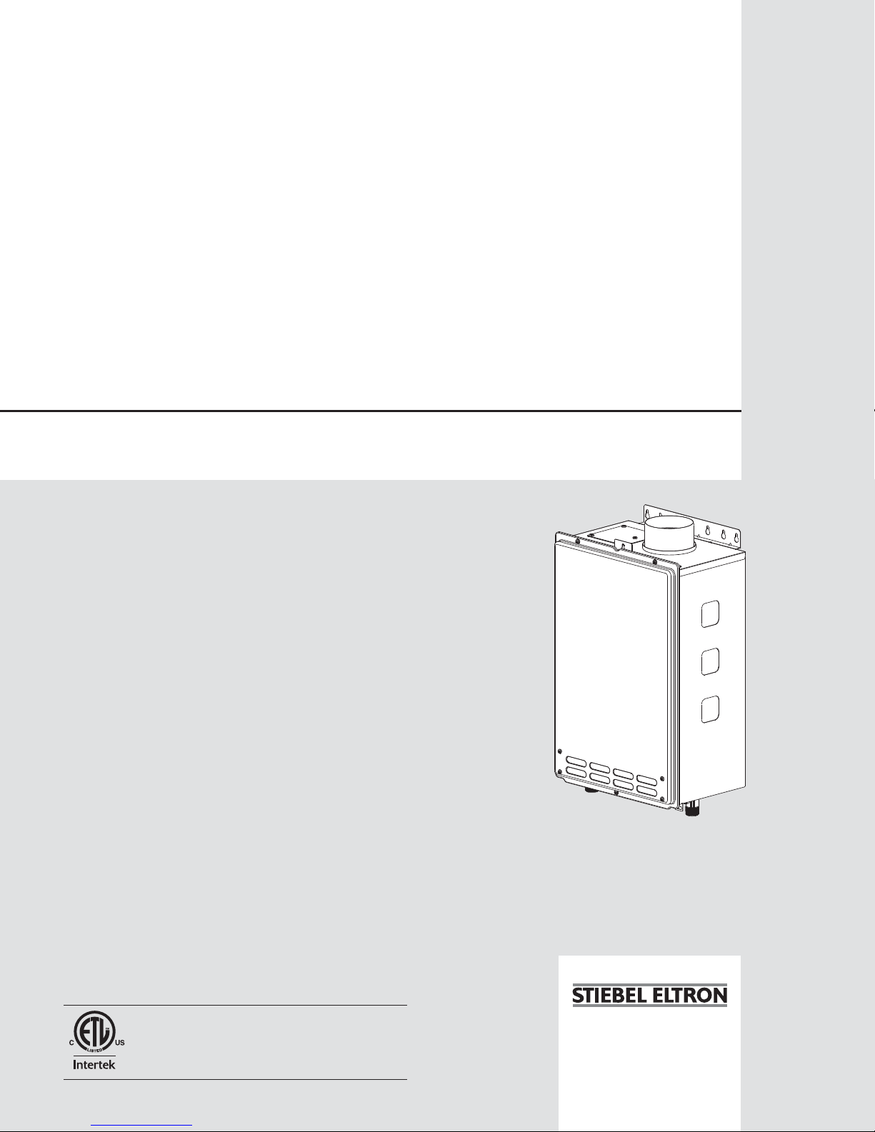
HydroShark 115 Gas Micro Boiler
Installation Manual and Owner’s Guide
The HydroShark 115 Gas Micro Boiler
is a compact and powerful residential unit
with a versatile BTU modulating range.
Featuring
• Effi ciency: 83 %
• Wall Hung
• Flow Activated: .75 GPM
• Copper Heat Exchanger
• Temperature Range: 99°-167° F*
• Freeze Protection
• Power Vent
• CAT III Stainless Steel Venting
*Max Water Temp of 167° F at 2.4 GPM
Models:
HydroShark 115NG
HydroShark 115LP
Do not return. Damages or repairs call
800.805.5384
If the information in these instructions is
not followed exactly, a fi re or explosion
may result causing property damage,
personal injury or death.
-Do not store or use gasoline or other fl ammable
vapors and liquids in the vicinity of this or any
other appliance.
-WHAT TO DO IF YOU SMELL GAS
• Do not try to light any appliance
• Do not touch any electric switch, do not use
any phone in your building.
• Immediately call your gas supplier from a
neighbor’s phone. Follow the gas supplier’s
instructions.
• If you cannot reach your gas supplier, call the
fi re department.
-Installation and service must be performed by
a qualifi ed installer, service agency or the gas
supplier.
2 | HYDROSHARK 115 WWW.HYDRO-SHARK.COM
Page 3

CONTENTS
Installation Manual
SPECIFICATIONS..........................................................................................................4
INTRODUCTIONS..........................................................................................................5
SAFETY GUIDELINES...................................................................................................6
INSTALLATION...............................................................................................................7
General................................................................................................................7
Clearances...........................................................................................................9
Included accessories............................................................................................9
High-altitude installations....................................................................................10
Venting instructions.............................................................................................11
Gas supply and gas pipe sizing..........................................................................17
Water connections..............................................................................................19
Electrical connections.........................................................................................20
APPLICATIONS..................................................................................................22
INITIAL OPERATION..........................................................................................24
OWNER’S GUIDE
OPERATING SAFETY...................................................................................................26
NORMAL OPERATION.................................................................................................28
General..............................................................................................................28
Temperature Settings.........................................................................................29
Flow....................................................................................................................30
Freeze protection system...................................................................................30
Maintenance and service...................................................................................31
Unit draining and fi lter cleaning..........................................................................31
TROUBLESHOOTING..................................................................................................32
General...............................................................................................................32
Error codes.........................................................................................................34
COMPONENTS DIAGRAM...........................................................................................37
PARTS LIST...................................................................................................................39
OUTPUT TEMPERATURE CHART...............................................................................41
WWW.HYDRO-SHARK.COM HYDROSHARK 115| 3
Page 4

Installation Manual
CONGRATULATIONS
Congratulations and thank you for choosing our micro boiler. Before use, we
recommend that you read through this installation manual carefully. Keep
this manual for future reference.
If you need an additional manual, contact the manufacturer or your local
distributor. When you call, please tell us the product name and the serial
number of your unit written on the rating plate of the boiler.
4 | HYDROSHARK 115 WWW.HYDRO-SHARK.COM
Page 5

SPECIFICATIONS
Model
Natural Gas Input
(OperaƟng Range)
Propane Input
(OperaƟng Range)
Gas ConnecƟon ¾” NPT
Water ConnecƟŽŶƐ
Water Pressure
Natural Gas
Inlet Pressure
Propane
Inlet Pressure
Manifold
Pressure**
Weight 33 lbs.
Dimensions
Natural
Propane 2.5” WC
HydroShark 115
Min: 19,500 Btu/h
Max: 140,000 Btu/h
Min: 19,500 Btu/h
Max: 140,000 Btu/h
¾” NPT
15 - 150 psi*
Min. 5.0” WC
Max. 10.5” WC
Min. 8.0” WC
Max. 14.0” WC
2.0” WC
H20.5” x W13.8” x D6.7”
IgniƟon
Supply
Electric
OperaƟon
Standby
Freeze-
ConsumpƟon
ProtecƟon
Electric IgniƟon
120 VAC / 60 Hz
73.1 W / 0.61 A
6.2 W / 0.05 A
111 W / 0.93 A
*18-25 PSI is recommended for maximum fl ow (Space Heating)
**The Manifold Pressure is the factory setting and generally should not need adjustment.
NOTE:
• Check the rating plate to ensure this product matches your specifi cations.
• The manufacture reserves the right to discontinue, or change at any time, specifi cations, or
designs without notice and without incurring obligation.
*When using boiler in-conjunction with HydroShark DHW Integrator Panel, system pressure may be much higher on your
domestic water side. Your space heating side should still refl ect the recommended 18-25 PSI for system pressure.
WWW.HYDRO-SHARK.COM HYDROSHARK 115| 5
Page 6
INTRODUCTION
• This manual provides information necessary for the installation, operation, and maintenance of the
boiler.
• The model description is listed on the rating plate which is attached to the side panel of the boiler.
• Please read all instructions completely before installing this product.
• If you have any problems or questions regarding this equipment, consult the manufacturer or its
local representative.
• This equipment is a micro boiler designed to effi ciently supply endless hot water for your needs.
(Radiant Heating, or Domestic Water used in-conjunction with Radiant Heating) See DHW Integrator Panel for more information on integrating domestic water with your radiant heating system.
• These boilers are only to be installed indoors.
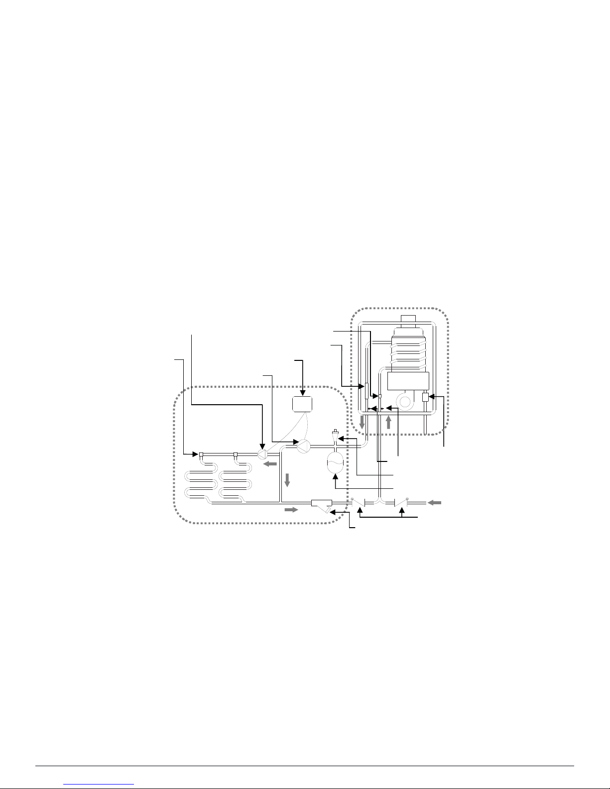
• The principle behind micro boilers is easy:
HydroShark 115
Secondary pump
Radiant heĂƟng
Water control valve
Pump controller
Primary pump
HeaƟng panel “Integrator”
Flow sensor
Burner
GAS
Gas valve
Thermistor
Air vent
Expansion tank
Water supply
Check valve
Strainer
*This diagram illustrates micro boiler design concepts only and does not accurately represent the
boilers physical description.
1. Your thermostat indicates a need for heat and turns on the circulator pump(s).
2. Water fl ows through the boiler.
3. The fl ow sensor detects the water fl ow.
4. The computer initiates the fan motor and sends a signal to the igniter to create an ignition spark.
5. The gas ignites and fl ames appear within the burner chamber.
6. Water circulates through the heat exchanger and then gets hot.
7. Using thermistors to measure temperatures throughout the micro-boiler, the computer modulates
the gas and water valves to ensure proper output water temperature.
8. When your room reaches desired temperature the pumps turn off and the boiler shuts down.
6 | HYDROSHARK 115 WWW.HYDRO-SHARK.COM
Page 7
SAFETY GUIDELINES
SAFETY DEFINITION
Indicates an imminently hazardous situation which, if not avoided, will result in
DANGER
WARNING
CAUTION
1. Follow all local codes , or in the absence of local codes, follow the current edition of the National
Fuel Gas Code: ANSI Z223.1/NFPA 54 in the USA or B149.1 Natural Gas, Propane Installation
Code in Canada.
2. Properly ground the unit in accordance with all local codes or in the absence of local codes, with
the National Electrical Codes: ANSI/NFPA 70 in the USA or CSA standard C22.1 Canadian Electrical Code Part 1 in Canada.
3. Carefully plan where you intend to install the micro boiler. Please ensure:
•Your micro boiler will have enough combustible air and proper ventilation
•Locate your micro boiler where water leakage will not damage surrounding areas.
4. Check the rating plate for the correct Gas Type, Gas Pressure, Water Pressure and Electric
Rating.
5. *If this unit does not match your requirements, do not install and consult with the manufacture.
6. If any problem should occur, turn off the unit and unplug the zone controls for the space heating
and/or DHW Integrator Panel system zone controls and turn off the gas. Then call a trained technician or the Gas Company or the manufacture.
death or serious injury.
Indicates an imminently hazardous situation which, if not avoided, could result in
death or serious injury.
Indicates an imminently hazardous situation which, if not avoided, could result in
minor or moderate injury.
GENERAL
• Water temperature over 125°F (52°C) can cause severe burns instantly or
death from scalding. The water temperature is set at 120°F (50°C) from the
factory to minimize any scalding risk. If using micro boiler with HydroShark
DHW Integrator Panel, always check the water temperature. Always verify
WARNING
WWW.HYDRO-SHARK.COM HYDROSHARK 115| 7
emitter water delivery temperature requirements to avoid damage.
• Do not store or use gasoline or other fl ammables, vapors, or liquids in the
vicinity of this appliance.
• Do not reverse the fl uid and/or gas connections as this will damage the gas
valves and can cause sever injury or death.
• Do not use this appliance if any part has been in contact with or been immersed in water. Immediately call a licensed plumber, a licensed gas fi tter, or
a professional service technician to inspect and/or service the unit if necessary.
• Do not disconnect the electrical supply if the ambient temperature will drop
below freezing. The freeze protection system only works if the unit has electrical power. The warranty will not be covered if the heat exchanger is damaged
due to freezing.
Page 8

INSTALLATION
GENERAL
1. Follow all local codes, or in the absence of local codes, follow the current edition of the National
Fuel Gas Code: ANSI Z223.1/NFPA 54 in the USA or B149.1 Natural Gas, Propane Installation
Code in Canada.
2. All gas micro boilers require careful and correct installation to ensure safe and effi cient operation.
This manual must be followed exactly. Read the “Safety Guidelines” section.
3. The manifold gas pressure is preset at the factory. It is computer controlled and should not need
adjustment.
4. Maintain proper space for servicing. Install the unit so that it can be connected or removed easily.
Refer to the “Clearances” section for proper clearance.
5. The micro boiler must be installed in a location where the proper amount of combustible air will be
available to it at all times without obstructions.
6. The electrical connections requires a means of disconnections, to terminate power to the micro
boiler for servicing and safety purposes.
7. Do not install the unit where the exhaust vent is pointing into any opening in the building or where
the noise may disturb your neighbors. Make sure the vent termination meets the required distance
by local code from any doorway or opening to prevent exhaust from entering a building.
8. Particles from fl our, aerosols, and other contaminants may clog the air vent, build up and reduce
the functions of the rotating fan, cause improper burning of the gas, or cause damage to the micro
boiler. Regularly ensure that the area around the unit is dust or debris free. Regular maintenance
is recommended for these types of environment.
9. If you will be installing the micro boiler in a contaminated area with a high level of dust, sand ,
fl our, aerosols or other contaminates/chemicals, they can become airborne and enter and build up
within the fan and burner causing damage to the micro boiler.
10. For the HydroShark 115:
• This unit may be converted to a direct-vent appliance by installing a direct-vent conversion kit.
(TK-TV10) which will bring in all required combustible air from outside the building. When installing
the direct-vent conversion kit, please follow all instructions included with the kit.
• If the boiler is used as a direct vent appliance, the unit requires 3” combustible air supply pipe. The
intake pipe must be sealed airtight. Air supply pope can be made of ABS, PVC, galvanized steel,
corrugated aluminum , corrugated stainless steel or Category III stainless steel.
• Terminating the venting through a sidewall is recommended for the direct-vent system.
• Running the exhaust vent and the intake pipe parallel is recommended.
• Terminate the exhaust and intake on the same wall / surface is recommended. Terminating the
same pressure zone allows for pressure balancing, which prevents nuisance shutdowns.
8 | HYDROSHARK 115 WWW.HYDRO-SHARK.COM
Page 9

WARNING
• Installation and service must be performed by a qualifi ed installer (for
example, a licensed plumber or gas fi tter, otherwise the warranty will be
void.
• The installer (licensed professional) is responsible for the correct installation for the micro boiler and for compliance with all national, state /
provincial, and local codes.
• The manufacturer does not recommend installing the micro boiler in a
pit or location where gas and water can accumulate.
• Do not have the vent terminal pointing toward any operating window, door, or
opening into a building.
• Do not install next to any source of airborne debris, such as clothes dryer, that
can cause debris to be trapped inside the combustion chamber, unless the
system is direct vented.
• The manufacturer does not recommend installing the micro boiler in an
attic due to safety issues. If you install the micro boiler in an attic:
-Keep the area around the micro boiler clean. When dust collects on the
fl ame sensor, the micro boiler will shut down on an error code.
-Place the unit for easy access for service and maintenance.
-A drain pan, or other means of protection against water damage, is to be
installed under the micro boiler in case of leaks.
-Make sure the unit will have enough combustion air and proper ventilation.
NOTICE
• The warranty will not cover damage cause by water quality.
-Only distilled water or distilled water/glycol mixtures can be used with this
micro boiler, unless when used in-conjunction with Stiebel Eltron DHW Integrator Panel system. Do not introduce pool or spa water, or any chemically treated
water into the micro boiler.
-Water hardness levels must not exceed 7 grains per gallon (120 ppm) for
single family applications or more than 4 grains per gallon (70 ppm) for all other
types of applications/ Water hardness leads to scale formation and may aff ect
/ damage the micro boiler. Hard water scaling must be avoided or controlled by
proper water treatment.
-Water pH levels must be between 6.5 and 8.5.
-Well water must be treated.
• Do no install the micro boiler where water, debris, or fl ammable vapors may
get into the fl ue terminal.
• Although the micro boiler is designed to operate with minimal sound, the
manufacturer does not recommend installing the unit on a wall adjacent
to a bedroom, or a room that is intended for quiet study or meditation,
etc.
• Locate your boiler close to a drain where water leakage will not do damage to
surrounding areas. As with any water heating appliance, the potential for leakage at some time in the life of the product does exist. The manufacturer will
not be responsible for any water damage that may occur. If you install a drain
pan under the unit, ensure that it will not restrict the combustion air fl ow.
WWW.HYDRO-SHARK.COM HYDROSHARK 115| 9
Page 10
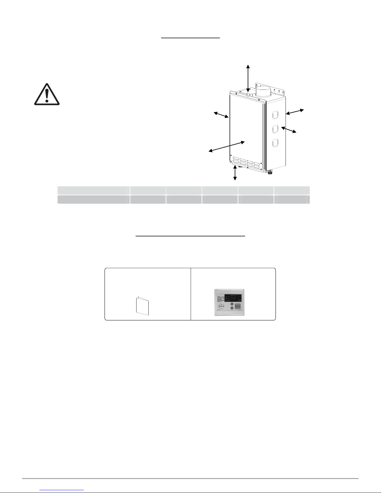
CLEARANCES
Maintain all clearances
around the micro boiler.
Failure to do so could cre-
WARNING
ate a fi re hazard, potentially
leading to death, serious
injury, and/or property damage.
Model Top BoƩom Front Back Sides
12” HydroShark 115* 12” 24” 1” 2 “
*Standard indoor installĂƟŽns and direct-vent indoor instalůĂƟŽns have the same clearances.
INCLUDED ACCESSORIES
Check that these items below are included with the micro boiler.
Side
Front
BoƩom
Top
Back
Side
1. InstallaƟon Manual and
Owner’s Guide
Qty: 1
2.
Remote controller
900766605 (TK-RE02)
Qty: 1
10 | HYDROSHARK 115 WWW.HYDRO-SHARK.COM
Page 11
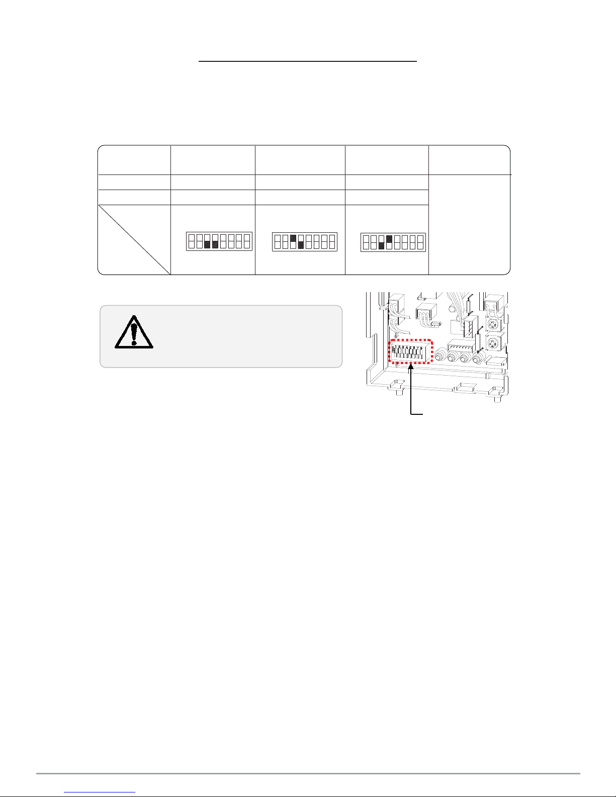
HIGH-ALTITUDE INSTALLATIONS
Check the elevation where your micro boiler is installed. Set DIPswitches shown in the table
below depending on the altitude.
AůƟƚƵĚĞ
Swiƚch NŽ.3
WARNING
0 ƚŽ 2,000 Ō
(DEFAULT)
OFF
OFF
࣭
࣮
࣯
ࣰ
ࣱ
ࣲ
2,000 ƚŽ 4,000 Ō
ࣳ
ࣴ
࣭
࣮
ON
OFF
࣯
ࣰ
ࣱ
ࣲ
Th Ğ ĚĂƌk sqƵĂƌĞs ŝŶĚŝĐĂƚĞ ƚhĞ
ĚiƌĞcƟŽn ƚhĞ ĚiƉƐǁŝƚĐŚĞƐ ƐŚŽƵůĚ
bĞ sĞƚ ƚŽ
4,000 ƚŽ 6,000 Ō
ࣳ
ࣴ
࣭
OFF
࣮
OvĞr 6,000 Ō
ON Swiƚch NŽ.4
ࣳ
࣯
ࣰ
ࣴ
ࣱ
ࣲ
DipswiƚĐhĞs
WWW.HYDRO-SHARK.COM HYDROSHARK 115| 11
Page 12
VENTING INSTRUCTIONS
GENERAL
• Improper venting of this appliance can result in excessive levels of carbon
monoxide which can result in severe personal injury or death.
DANGER
CAUTION
This appliance must be vented in accordance with the section” Venting of Equipment” of the current
edition of the National Fuel Gas Code: ANSI Z223.1/NFPA 54 in the United States and/or Section 8 of
the B149.1 Natural Gas and Propane Installation Code in Canada, as well as applicable local building
codes. The manufacturer recommends NovaVENT or Z-Vent Category III, single wall, stainless steel
venting.
The boiler can obtain its combustion air from the space that it is installed in or it can be direct vented
using the direct vent conversion kit (TK-TV10). Ensure the location has suffi cient, clean combustion
air.
General rules for venting micro boilers are:
• Improper installation can cause nausea or asphyxiation, severe injury or death
from carbon monoxide and fl ue gases poisoning. Improper installation will
void product warranty.
When installing the vent system, all applicable national and local codes must be
followed. If you install thimbles, fi re stops or other protective devices and they
penetrate any combustible or noncombustible construction, be sure to follow all
applicable national and local codes.
• Place the micro boiler as close as possible to the vent termination.
• The vent collar of the micro boiler must be fastened directly to an unobstructed vent pipe.
• Do not weld the vent pipe to the micro boiler’s vent collar.
• Do not cut the vent collar of the unit.
• The vent must be easily removable from the top of the boiler for normal service and inspection of
the unit.
• The micro boiler vent must not be connected to any other gas appliance or vent stack except an
approved common venting system.
• Avoid using an oversized vent pope or using extremely long runs of the pope unless it is part of an
approved common vent system.
• For rooftop venting, a rain cap or other from of termination that prevents rain water from entering
into the micro boiler must be installed.
• Do not terminate vent into chimney. If the vent must go through the chimney, the vent must run all
the way through the chimney with approved vent pipe.
General rules for vent terminations:
• Avoid locating the micro boiler vent termination near any air intake devices. These fans can pick
up the exhaust fl ue products from the micro boiler and return them to the building. This can create
a health hazard.
• Locate the vent termination so that it cannot be blocked by any debris, at any time. Most codes require that the termination be at least 12 in. (305 mm) above grade, but the installer may determine
if it should be higher depending on the job site condition and applicable codes.
• A proper sidewall termination is recommended when the micro boiler is vented through a sidewall.
• Be sure to check the clearance form the exhaust termination to the air inlet or opening in the vent
termination clearances section.
12 | HYDROSHARK 115 WWW.HYDRO-SHARK.COM
Page 13

NOTICE
WARNING
Combustion Air Supply
• The guidelines in this section apply to installations within the United Sates. All
U.S. installation must conform to the National Fuel Gas Code, ANSI Z223.1/
NFPA 54 (current edition) and local codes.
• Canadian requirements diff er from the guidelines in this section. In Canada,
follow the requirements of B149.1 (Natural Gas and Propane Installation Code,
current edition) as well as local and provincial codes. Contact your local code
enforcement agency for direction.
This micro boiler requires an adequate source of clean air for combustion and
ventilation. Without suffi cient air, your boiler may not operate properly and may emit
excessive and abnormal amounts of carbon monoxide which may result in carbon
monoxide poisoning or death.
Before installing the boiler, you must determine the amount of air needed to supply this boiler and an
other gas appliances in the same area and provide adequate air for combustion and ventilation. Consult a qualifi ed person if you’re unsure of the proper way to supply air to your boiler.
Check for Chemicals:
Air for combustion and ventilation must be clean and free of corrosive chemicals. If corrosive chemicals, such as sulfur, fl ouring, or chlorine are present, the boiler must be direct vented. Failure due to
these corrosive chemicals is not covered by the warranty.
WARNING!
In all cases, ensure that corrosive chemicals are not present at the air intake. Presence of such
chemicals at the air intake could result in death, personal injury, or property damage. Examples of
locations that require outside air due to chemicals include:
• Beauty salons
• Photo processing labs
• Indoor pools
• Laundry, hobby, or craft rooms
• Chemical storage areas
Products such as aerosol sprays, detergents, bleaches, cleaning solvents, gasoline, air fresheners,
paint, varnish removers, and refrigerants should not be stored or used near the micro boiler.
WWW.HYDRO-SHARK.COM HYDROSHARK 115| 13
Page 14
Exhaust Venting
This is a Category III appliance and must be vented accordingly. The vent system must be sealed
airtight. All seams and joints without gaskets must be sealed with high heat resistant silicone sealant
or UL listed aluminum adhesive tape having a minimum temperature rating of 350° F. For best results,
a vent system should be as short and straight as possible.
• This boiler is a Category III appliance and must be vented accordingly with any 4” vent approved
for use with Category III or Special BH type gas vent.
• Follow the vent pipe manufacturer’s instructions when installing vent pipe.
• Do not common vent this appliance with any other vented appliance. (Do not terminate vent
into a chimney. if the vent must go through the chimney, the vent must run all the way through the
chimney with Category III approved or Special BH vent pipe.)
• When the horizontal vent run exceeds 5 ft. (1.5 m), support the vent run at 3 ft. (0.9 m) intervals
with overhead hangers.
• When th event run exceeds 5 ft. (1.5 m), a condensate drain is recommended. It should be installed as close to the boiler as possible.
• The maximum length of exhaust vent piping must not exceed 50 ft. (15.2 m) (deducting 5 ft. (1.5
m) for each elbow used in the venting system.) Do not use more than 5 elbows.
Diameter Max. No. of Elbow Max. VerƟcal and Horizontal (Total) Vent Length
4” 5 50 Ō.
*For each elbow added, deduct 5 Ō. from max. Vent length.
No. of Elbows
0 50 Ō
1 45 Ō
2 40 Ō
5 25 Ō
Max. sĞƌƟĐĂů or Horizontal Length
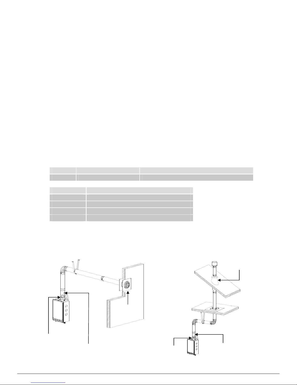
Horizontal InstallaƟŽŶ Diagram
BackŇow Preventer*
VerƟcal CondensaƟon Drain**
Venting Illustrations
Wall
Sidewall Vent
Terminator
BackŇow Preventer *
VerƟcal InstallaƟon Diagram
Rain Cap
Roof Flashing
Roof
sĞƌƟĐĂů CondensaƟon
Drain**
14 | HYDROSHARK 115 WWW.HYDRO-SHARK.COM
Page 15

Venting Illustrations
Horizontal InstallaƟŽŶ Diagram
(With direct-ǀĞŶƟŶŐͿ
BackŇow
Preventer *
sĞƌƟĐĂů CondensaƟon Drain**
See the picture below for detailed connecƟon
instrucƟons to the Direct-Vent Conversion Kit.
Wall
Sidewall
Vent
Terminator
sĞƌƟĐal InstĂůůĂƟŽŶ Diagram
(With direct-venƟŶŐͿ
Rain Cap
Roof
BackŇow
Preventer *
VerƟcal
CondensaƟŽn
Drain**
Roof Flashing
Fire stop
*BackŇow Preventer (Recommended for freezing weather condiƟons: 36°F and below)
**VerƟcal CondensaƟon Drain must be installed accordance with local codes.
Horizontal /ŶƐƚĂůůĂƟŽŶ Diagram
With Direct-Vent Concentric
InstallaƟon Di agram of Direct-Vent
Conversion Kit
TerminaƟŽn
Wall
Plate of Direct-Vent Conversion Kit
Direct-vent
Concentric
TerminaƟon
Intake port of
Direct-Vent
Conversion Kit
WWW.HYDRO-SHARK.COM HYDROSHARK 115| 15
Page 16

Vent Termination Clearances
Canada U.S.A
Direct vent and
other than Direct
Vent
Clearance above grade, veranda, porch, deck,
A 1 foot 1 foot
or balcony.
Clearance to window or door that may be
B
opened.
Clearance to permanently closed window
C * *
VerƟcal clearance to veŶƟůĂted soĸt located
above the vent terminator within a horizontal
D
distance of 2 feet (61cm) from the center line
of the terminator.
E * * *
Clearance to unvenƟlated soĸt
Clearance to outside corner
F
Clearance to inside corner
G
Clearance to each side of center line extended
H
above meter/regulator assembly
Clearance to service regulator vent outlet.
I
Clearance to non-mechanical air supply inlet
J
to building or the combusƟon air inlet to any
other appůŝĐĂƟon.
Clearance to mechanical air supply inlet.
K
Clearance above paved sidewalk or paved
L
driveway located on public property.
Clearance under veranda, porch deck, or
M
balcony.
*For clearances not spĞĐŝĮĞĚ in ANSI Z223.1 / NFPA 54 or CAN/CSA-B149.1, please use clearances in accordance with
local installaƟon codes and the requirements of the gas supplier.
3 feet 1 foot
* * *
** *
** *
3 feet 1 foot
6 feet 3 feet
Direct vent
* 3 feet *
*3 feet
* 7 feet 7 feet
* * 1 foot
Other than Direct Vent
4 feet from below or side
opening. 1 foot from
4 feet from below or side
opening. 1 foot from
1 foot
above opening.
*
*
above opening.
3 feet
16 | HYDROSHARK 115 WWW.HYDRO-SHARK.COM
Page 17

Please follow all local and naƟŽnal codes in regards to proper terminaƟŽŶ clearances.
In the absence of such codes, the following clearances can be used as guidelines. Local
CAUTION
codes supersede these guidelines.
For sidewall terminaƟons
2Ō.
1Ō.
1Ō.
Inside
corner
Exhaust terminaƟŽŶ
For ŵƵůƟƉle sidewall exhaust
terminaƟons (e.g. mulƟ-unit
systems), an exhaust terminaƟŽŶ
must be at least 1 Ō. away from
another exhaust teƌŵŝŶĂƟŽŶ An
exhaust terminaƟon must also be
at least 2 Ō away from an inside
corner (if the adjacent wall is less
than 2 Ō. of length, the minimum
required distance away from the
inside corner will be equal to the
length of that adjacent wall).
ϯŌ.
ϯŌ.
3Ō.
Air supply inlet
For direct-vent sidewall
terminĂƟŽŶƐ that use two
separate penetraƟŽns for the
intake and exhaust, distance
the intake and exhaust
terminĂƟŽŶƐ at least 3 Ō away
from each other, no maƩer the
orientaƟon.
2Ō.
ϭŌ.
1Ō.
Inside
corner
Direct vent ƚĞƌŵŝŶĂƟŽŶ
For ŵƵůƟƉle-unit, direct-vent sidewall
terminaƟons that combine the intake
and exhaust into a single penetraƟon,
space each direct-vent terŵŝŶĂƟŽŶ at
least 1 Ō. away from each other, no
maƩer the orientaƟon. A direct-vent
terminaƟon must also be at least 2 Ō.
away from an inside corner (if the
adjacent wall is less than 2 Ō. of
length, the minimum required
distance away from the inside corner
will be equal to the length of that
adjacent wall).
2Ō.
Exhaust
terminaƟon
Exhaust and/or direct-vent
sidewall terminaƟŽŶƐ should
be at least 2 Ō away from an
opposite surface/wall. Do
not place the terminaƟon
directly in front of an
opening into a building.
For roŽŌŽƉ terminaƟons
A
A
ϮŌ.
A
A
A
Air intake
Exhaust terŵŝŶĂƟon
A: In accordance with local codes
Exhaust
terminaƟon
Air intake
For ŵƵůƟƉle-unit rooŌŽƉ teƌŵŝŶĂƟons (whether for standard indoor or
direct-vent installĂƟons) space all exhaust and intake terminaƟons in
accordance with local codes. An exhaust terminaƟon must be spaced from
a wall or surface in accordance with local codes as well. In the absence of
such a code, an exhaust terminaƟŽŶ must be a horizontal distance of at
least 2 Ō. away from a wall or surface.
WWW.HYDRO-SHARK.COM HYDROSHARK 115| 17
Page 18

GAS SUPPLY AND GAS PIPING SIZE
• Check that the type of gas matches the rating plate fi rst.
• Ensure that any and all gas regulators are operating properly and
providing gas pressures withing the specifi ed range shown below.
CAUTION
• The minimum and maximum inlet gas pressures are:
Excess gas inlet pressure may cause serious accidents.
• Conversion of this unit from natural gas to propane or vice versa will void all
warranty. Contact your local distributor to get the correct unit for your gas
type. The manufacturer is not liable for nay property and/or personal
damage resulting from gas conversions.
Gas type
Natural Gas Min. 5.0” WC – Max. 10.5” WC
Propane Min. 8.0” WC – Max. 14.0” WC
Inlet gas pressure
• Inlet gas pressures that fall outside the range of values listed above may adversely aff ect the performance of the micro boiler. These pressures are measured when the micro boiler is in full operation.
• Inlet gas pressure must not exceed the above maximum values; gas pressure above the specifi ed
range will cause dangerous operating conditions a damages to the unit.
• Until testing of the main gas line supply pressure is completed, ensure the gas line to the micro
boiler is disconnected to avoid any further damage.
Gas connections
1. Install a manual gas shutoff valve between the micro boiler and the gas supply.
2. When the gas connections are completed, it is necessary to perform a gas leak test either by
applying soapy water to all gas fi ttings and observing for bubble or by using a gas leak detection
device.
• The micro boiler and its individual shutoff valve must be disconnected from the gas supply piping system during any pressure testing of that system at the test pressures in excess of 1/2 psi
(3.5kPa).
• The micro boiler must be isolated from the gas supply piping system by closing its individual
manual shutoff valve during any pressure testing of the gas supply piping system at test pressures
equal to or less than 1/2 psi (3.5 kPa).
3. Always purge the gas line of any debris and/or water before connecting to the gas inlet.
Size the gas pipe appropriately to supply the necessary volume of gas required for
NOTICE
the micro boiler using ANSI Z223.1/NFPA 54 in the USA of B149.1 in Canada or
local codes. Otherwise, fl ow capabilities and output temperatures will be limited.
18 | HYDROSHARK 115 WWW.HYDRO-SHARK.COM
Page 19

Natural Gas Supply Piping
Maximum delivery Capacity of Cubic Feet of Gas per Hour of IPS Pipe carrying Natural Gas with 0.60
Specifi c Gravity Based on Pressure Drop of 0.5”W.C.
Based on Energy Content of 1,000 BTU/Cubic ft.: The micro boiler requires 140 Cubic ft./hr.
Unit: Cubic Feet per Hour
Pipe Size
Diameter 10’ 20’ 30’ 40’ 50’ 60’ 70’ 80’ 90’ 100’ 125’ 150’ 200’
¾” 363 249 200 171 152 138 127 118 111 104 93 84 72
1” 684 470 377 323 286 259 239 222 208 197 174 158 135
1 ¼” 1,404 965 775 663 588 532 490 456 428 404 358 324 278
1 ½” 2,103 1,445 1,161 993 880 798 734 683 641 605 536 486 416
2” 4,050 2,784 2,235 1,913 1,696 1,536 1,413 1,315 1,234 1,165 1,033 936 801
Length
Propane (LP) Supply Piping
Maximum Capacity of Propane (LP) Based on 11” W.C. supply pressure at 0.5” W.C. pressure drop.
Unit: kBTU per Hour
Pipe Size
Diameter
10’ 20’ 30’ 40’ 50’ 60’ 70’ 80’ 90’ 100’ 125’ 150’ 200’
¾” 567 393 315 267 237 217 196 185 173 162 146 132 112
1” 1,071 732 590 504 448 409 378 346 322 307 275 252 213
1 ¼” 2,205 1,496 1,212 1,039 913 834 771 724 677 630 567 511 440
1 ½” 3,307 2,299 1,858 1,559 1,417 1,275 1,181 1,086 1,023 976 866 787 675
2” 6,221 4,331 3,465 2,992 2,646 2,394 2,205 2,047 1,921 1,811 1,606 1,496 1,260
For more informaƟŽn, please see the below.
Length
Based on Energy Content of 1,000 BTU/Cubic ft.
Divide each appliance’s BTU/h requirement by 1,000 BTU/ft³ to get the
appliances ft³/h requirement.
Take into account the distance the appliance is from the
gas meter, look in the above gas chart to properly size
the line.
For sections of the gas line supplying gas to more than
one appliance (Ex. Point A to Point B), add up the cubic
ft. per hour requirements of the appliances that are
being supplied by that section, and size to the farthest
appliance.
For Example: The section from A to B supplies gas
to the furnace, range and dryer. Adding up the BTU/h
requirements and dividing by 1,000 yields a cubic ft. per
hour requirements of 220 cubic ft. of gas per hour. The
5’ Le
ngth
1-1/4” Pipe Size
5’ Length
1-1/4” Pipe Size
Gas Meter
farthest appliance is the range, which is 50 ft. away form
the meter. Looking at the above chart, and under column
of 50 ft., Section A to B needs to be 1” in order to supply 220 cubic ft.
Micro
Boiler
199,000BTU
10’ Length
3/4” Pipe Size
A
10’ Length
1” Pipe Size
Gas Sizing Example
(Natural Gas)
15’ Length
B
1” Pipe Size
10’ Length
3/4” Pipe Size
Furnace
120,000BTU
Dryer
35,000BTU
10’ Length
15’ Length
C
Range
65,000BTU
WWW.HYDRO-SHARK.COM HYDROSHARK 115| 19
Page 20

Measuring inlet gas pressure
1. Turn off all electric power to the micro boiler if service is to be performed.
2. Turn the manual gas valve located on the outside of the unit clockwise to
the off position.
WARNING
3. Failure to follow these steps could lead to a fi re or explosion, resulting in
personal injury or death.
The micro boiler cannot perform properly without suffi cient inlet gas pressures. Below are instructions
on how to check the inlet gas pressure.
THIS IS ONLY TO BE DONE BY A LICENSED PROFESSIONAL.
1. Shut off the manual gas valve on the gas supply line.
2. Remove the screw for the pressure port located on the
gas inlet of the micro boiler shown in the diagram on the
right.
3. Connect the manometer to the pressure port.
4. Re-open the manual gas valve. Check to see that there
are no gas leaks.
5. Check in inlet gas pressure. When the micro boiler is on
maximum and minimum burn, the manometer should
read from 5.0” W.C. to 10.5” W.C. (1.24 to 2.61 kPa) for
Natural Gas, from 8.0” to 14.0” W.C. (1.99 to 3.48 kPa)
for Propane.
Pressure port
WATER CONNECTIONS
Do not use the micro boiler if any part has been under water. Immediately
contact a qualifi ed installer or licensed professional to inspect the boiler to
WARNING
NOTICE
determine if it needs to be replaced.
Do not reverse the hot outlet and cold inlet connections to the micro boiler.
This will not properly activate the micro boiler.
All pipes, pipe fi ttings, valves and other components, including soldering materials, must be suitable
for potable water systems (when using DHW Integrator Panel), or distilled water or distilled water/glycol mix.
1. A manual shutoff valve must be installed on the cold
water inlet to the micro boiler between the main water
supply line and the micro boiler.
2. In addition, a manual shutoff valve is also recommended on the hot water outlet of the unit. If the micro boiler
is installed within, or subjected to, a closed loop system
As Close as
Possible
(recommended), a thermal expansion tank or code
approved device to handle the thermal expansion must
be installed.
3. Before installing the micro boiler, fl ush the water line
Pressure
Relief Valve
Hot
outlet
Cold
inlet
Gas
inlet
to remove all debris, and after installation is complete,
purge the air from the line. Failure to do so may cause
damage to the boiler.
20 | HYDROSHARK 115 WWW.HYDRO-SHARK.COM
Page 21

Pressure relief valve
The micro boiler has a high-temperature shutoff switch built in as a standard safety feature (called a
Hi-Limit switch) therefore a “pressure only” relief valve is required.
• This unit does not come with an approved pressure relief valve.
• An approved pressure relief valve must be installed on the hot water outlet.
• The pressure relieve vale must conform to ANSI Z21.22 or Can 1-4.4 and installation must follow
local codes.
• The discharge capacity must be at least 140,000 BTU/h.
• The pressure relief valve needs to be rated for a maximum of 150 psi (1 MPa).
• The discharge piping for the pressure relief valve must be directed so that the hot water cannot
splash on anyone or on nearby equipment.
• Attach the discharge tube to the pressure relief valve and run the end of the tube to within 6
in.(152 mm) from the fl oor. This discharge tube must allow free and complete drainage without any
restrictions.
• If the pressure relive valve installed on the micro boiler discharges periodically, this may be due to
a defective thermal expansion tank or defective pressure relief valve.
• The pressure relief valve must be manually operated periodically to check for correct operation.
• No valve must be placed between the relief valve and the micro boiler.
WARNING
ELECTRICAL CONNECTIONS
• Follow the electrical code requirements of the local authority having jurisdiction. In the absence of such requirements, follow the current edition of the National Electrical Code ANSI/NFPA 70 in the U.S. or the current edition of CSA
C22.1 Canadian Electrical Code Part 1 in Canada.
• When servicing or replacing parts with the micro boiler, label all wires prior to
disconnection to facilitate an easy and error-free reconnection. Wiring errors
can cause improper and dangerous operation. Verify proper operation after
servicing.
• Failure to observe these warnings could result in personal injury or loss of life.
This unit comes with a power plug instead of a junction box.
WWW.HYDRO-SHARK.COM HYDROSHARK 115| 21
Page 22

REMOTE CONTROLLER CONNECTIONS
<How to connect the remote controller to the micro boiler>
1. Disconnect power supply from the micro boiler.
2. Take Žī the micro boiler front cover.
3. Locate the remote controller terminal, pictured below (located around the lower right-hand
side of the computer board).
4. Open the plasƟĐ cover of the remote controller, and then aƩach the two fork terminals to
connector base of the backside the remote controller with two screws. Make sure the
terminals are Įrmly Įxed.
5. Pull the remote’s wires through the hole at the boƩom of the water heater’s casing.
6. Properly ĂƩĂĐŚ the remote’s wires to the remote controller terminal on the computer board.
(No polarity)
*Do NOT jump or short-circuit the wires or computer will be damaged.
7. Replace Front Cover securely.
8. Wires used for the remote controller connecƟon must be:
Minimum 18AWG wire (No polarity)
Maximum 400 feet long
*For detailed ĐŽŶŶĞĐƟŽŶ instrucƟons to the remote controller, refer to the instrucƟons that are
packaged with the remote controller.
Remote controller terminal inside micro boiler
Connect to these
terminals
Front of remote
9007666005
(TK-RE02)
Connect other end to these terminals
Back of remote
22 | HYDROSHARK 115 WWW.HYDRO-SHARK.COM
Page 23

APPLICATIONS
Space Heating Applications
• In order to purge air in water pipes within a closed loop system, an air vent,
air separator, and expansion tank should be installed in the system. (Hydro-
Shark pre-built space heating panels incorporate all of these features).
WARNING
HydroShark per-plumbed panels help make space heating easy and reliable. These panels are professionally engineered and use proven Primary/Secondary hydronic practices. Call Tech Support
(800.805.5384) for assistance.
• Water temperature over 125° F (52° C) can cause sever burns instantly of
death from scalding.
• Chemicals such as diluted Glycol can be used for radiant fl oor, Hydro/fan
coil air or Baseboard heating only. The diluted solution of glycol must contain
between 25% and 55% of Glycol. Be aware that in a closed loop system, low
pressure in the heat exchanger can cause low-temperature boiling, resulting
in excessive noise and damage to the micro boiler. Consult with the glycol
maker for specifi cations prior to use.
HydroShark Pre-Built Space Heating Panels
Sample:
Master Panel Single:
For more information on HydroShark pre-plumbed panels and zoning options for this boiler please
visit www.hydro-shark.com or call 800.805.5384
WWW.HYDRO-SHARK.COM HYDROSHARK 115| 23
Page 24

Dual-purpose hot water heating
(Domestic and Space Heating)
Insert a HydroShark DHW Integrator Panel to provide potable heated water and Hydronic Heating
(with space heating panel(s)) with one heat source.
The HydroShark DHW Integrator Panel integrates with a wide variety of boilers and delivers “Priority”
potable heated water with no storage tank and hydronic space heating in a small reliable package.
Follow all local codes, or in the absence of local codes, follow the most recent
NOTICE
edition of the National Standard Code, ANSI Z21.10.3.
For more information on HydroShark DHW Integrator Panels and integrating space heating and domestic water for this boiler please visit www.hydro-shark.com or call 800.805.5384.
24 | HYDROSHARK 115 WWW.HYDRO-SHARK.COM
Page 25

INITIAL OPERATION
• Check the Gas and Water Connections for leaks before fi ring the unit for the fi rst time.
• Open the main gas supply valve to the unit using only your had to avoid and spark. Never use
tools. If the knob will not sure by had, do not try to force it; call a qualifi ed service technician.
Forced repair may result in a fi re or explosion due to gas leaks.
• Be sure to check for the presence of leaking gas toward the bottom of the unit because some gases are heavier than air and may settle towards the fl oor.
• Check the Gas Pressure.
• Do not try to light the burner manually. It is equipped with an electric ignition device which automatically lights the burner.
• Check for proper venting and combustible air to the micro boiler.
• Purge the gas and water lines to remove any air pockets.
• Do not use this micro boiler if any part has been under water. Immediately call a qualifi ed installer
or service technician to inspect the micro boiler to determine if it needs replacement.
IF YOU SMELL GAS:
• Do not try to start the micro boiler.
• Do no touch any electric switches; do not use any phone in your building.
• Immediately call your gas supplier from a neighbor’s phone. Follow the gas
WARNING
supplier’s instructions.
• If you cannot reach your gas supplier, call the fi re department.
WWW.HYDRO-SHARK.COM HYDROSHARK 115| 25
Page 26

Owner’s Guide
CONGRATULATIONS
Congratulations and thank you for choosing our micro boiler. Before
use, we recommend that you read through this owner’s guide carefully.
Keep this manual for future reference.
If you need an additional manual, contact the manufacturer or your local
distributor. When you call, please tell us the product name and the serial
number of your unit written on the rating plate of the boiler.
26 | HYDROSHARK 115 WWW.HYDRO-SHARK.COM
Page 27

OPERATING SAFETY
FOR YOUR SAFETY READ BEFORE OPERATING
WARNING: If you do not follow these instructions exactly, a fi re or explosion may result
causing property damage, personal injury or loss of life.
1. The micro boiler does not have a pilot. It is equipped with an ignition device that automatically
lights the burner. Do NOT try to light the burner by hand.
2. Before operating smell all around the micro boiler area for evidence of leaking gas. Be sure to
smell next to the fl oor because some gas is heavier than air and will settle on the fl oor.
WHAT TO DO IF YOU SMELL GAS:
• Do not try to light any appliance.
• Do not touch any electric switch; do not use any phone in your building.
• Immediately call your gas supplier from a neighbor’s phone.
• Follow the gas suppliers instructions. If gas supplier cannot be reached, call fi re dept.
3. Use only your hand to turn the gas shutoff valve. Never use tools. If the valve will not turn by hand,
don’t try to repair it, call a qualifi ed service technician. Force or attempted repair may result in a
fi re or explosion.
4. Do not use this micro boiler if any part has been under water. Immediately call a qualifi ed service
technician to inspect the micro boiler and to replace the unit if needed.
OPERATING INSTRUCTIONS
1. STOP! Read the safety information above or in the Owner’s Manual.
2. Turn off all electric power to the micro boiler.
3. Do not attempt to light the burner by hand.
4. Turn the manual as valve located on the outside of the unit clockwise to the OFF position.
5. Wait fi ve (5) minutes to clear out any gas. If you then smell gas, STOP! Follow “B” in the safety
information above on this label. If you don’t smell gas, go to next step.
6. Turn the manual gas valve located on the outside of the unit counterclockwise to the ON position.
7. Turn on all electrical power to the micro boiler.
8. If the micro boiler will not operate, follow the instructions “To turn off Gas to appliance” and call
your service technician or gas supplier.
TO TURN OFF GAS TO APPLIANCE
1. Turn off all electric power to the micro boiler if service is to be performed.
2. Turn the manual gas valve located on the outside of the unit clockwise to the OFF position.
WWW.HYDRO-SHARK.COM HYDROSHARK 115| 27
Page 28

DANGER
Vapors from fl ammable liquids will explode and catch fi re causing death or sever burns.
Do not use or store fl ammable products such as gasoline, solvents or adhesives in the same
room or area near the micro boiler.
Flammable Vapors
Read and follow micro boiler warnings and instructions. If the owner’s manual is missing,
contact the manufacturer.
Keep fl ammable products: Vapors:
1. Far away from boiler.
2. In approved containers.
3. Tightly closed and out of reach of children.
4. Micro boiler has a main burner, which may
come on at any time and will ignite fl am-
1. Cannot be seen.
2. Are heavier than air.
3. Go a long way on the fl oor.
4. Can be carried form other rooms to the
main burner by air currents.
mable vapors.
DANGER
When using micro boiler with DHW Integrator Panel for Domestic Hot Water:
1. Water temperature over 125° F can cause severe burns instantly or death from scalds.
2. Children, disabled and elderly are at highest risk of being scalded
3. Feel water before bathing or showering.
4. Temperate limiting valves are available on the DHW Integrator Panel(s). Adjust these mixing
valves accordingly.
5. The outlet temperature of the micro boiler is set at 120° F (50° C). If you require water temperatures below this setting, follow the instruction manual.
6. Test the boiler before bathing or showering. Do not leave children or an infi rm person unsupervised.
28 | HYDROSHARK 115 WWW.HYDRO-SHARK.COM
Page 29

NORMAL OPERATION
TEMPERATURE CONTROLLER AND REMOVE CONTROLLER
The illustration below shows an example of the controllers. The exact display may diff er from examples.
GENERAL
• Water temperatures over 125° F (52° C) can cause sever burns instantly or
death from scalding.
WARNING
NOTICE
• The outlet hot water temperature of the boiler is factory set at 120° F.
• Flow rate to active micro boiler: 0.75 gallon per minute at the default set
temperature
• Flow rate to keep the micro boiler running: 0.4 gallon per minute.
OPERATION
<Set temperature>
1. Turn on the 120 VAC power supply to the micro boiler.
2. Press the "OPERATION" buƩon on the remote in order to turn the remote controller on. It shows the
set temperature on its display as shown the picture to the below.
3. Press the "HOT" bu
4. You can set the temperature from 99°F (38°C) to 167°F (75°C).
<Exterior view of the remote controller>
"INFOMATION" BuƩon
<The temperature opƟons>
99 100
Ʃon or the "COLD" ďƵƩon to set the temperature seƫng of the unit.
"HOT" BuƩon
"OPERATION" BuƩon
"COLD" BuƩon
102 104 106 108 110 111 113 115 117 122 131 140 158 167
Temperature above 122°F (50°C) can cause severe burns or death from
scalding. Children, disabled
CAUTION
WWW.HYDRO-SHARK.COM HYDROSHARK 115| 29
and the elderly are at high risk of being injured.
Page 30

TEMPERATURE SETTINGS
Set Temperature
-Without remote controller-
There are 4 temperatures that you can select from by changing the dipswitch seƫngs on the
computer board without the remote controller. See the table below.
Temperatures available
113°F 122°F 131°F 140°F
For detailed dipswitch seƫngs for each temperature see below.
The temperature has been preset at the factory to 120°F (50°C).
If temperatures other than the ones listed above are required, the remote controller can
provide several more temperature opƟons.
-Dipswitch seƫngs for each temperature on the computer board-
Temperature Seƫngs
࣭
ࣿࣥ
࣭࣭࣯
ࣰࣱࣤ
WARNING
࣮
ࣳ
࣯
ࣴ
ࣱ
ࣰ
ࣲ
࣭࣮࣮
ࣱࣤ࣬ ࣿࣥ
ࣽ
Turn oī the power supply to the
micro boiler before changing the
dipswitch seƫŶŐƐ
Only change the switches with the
dark squares. The dark squares
indicate which direĐƟŽŶ the
dipswitch should be set to.
࣭
࣮
ࣳ
࣯
ࣴ
ࣰ
ࣱ
ࣲ
࣭࣯࣭
ࣱࣱࣤ
ࣿࣥ
࣭
࣮
ࣳ
࣯
ࣴ
ࣱ
ࣰ
ࣲ
ࣰ࣭࣬
ࣲࣤ࣬
ࣿࣥ
࣭
࣮
ࣳ
࣯
ࣴ
ࣰ
ࣱ
ࣲ
Dipswitches
30 | HYDROSHARK 115 WWW.HYDRO-SHARK.COM
Page 31

FLOW
• The fl ow rate through the micro boiler is limited to a maximum of 6.6 GPM (38 L/min).
• The temperature setting, along with the supply temperature of the water will determine the fl ow
rate output of the unit.
FREEZE PROTECTION SYSTEM
• This unit comes equipped with heating blocks to protect it against damages associated with freezing.
• For this freeze protection system to operate, there has to be electrical power to the unit. Damage
to the heat exchanger caused by freezing temperates due to a power loss is not covered under
warranty. In cases where power losses can occur, consider the use of a backup power supply.
• The freeze protection system will activate when the surrounding and/or outside temperature drop
below 36.5°F (2.5° C).
• It is the installer’s responsibility to be aware of freezing issues and take all preventive measures.
The manufacture will not be responsible for any damage to the heat exchanger as a result of
freezing.
• In any area subject to freezing temperatures, freezing issues can occur if cold air enters through
the venting into the heat exchanger by either negative pressures within the installation location or
by strong outside wind. The manufacturer highly recommends the use of a back fl ow preventer
(sold separately) to minimize the amount of cold air entering through the exhaust venting when the
micro boiler is off .
• It is the installer’s responsibility to be aware of freezing issues and take all preventive measures.
The manufacture will not be responsible for any damage to the heat exchanger as a result of
freezing.
• If you will not be using your boiler for a long period of time:
1. Completely drain the water out of the unit.
2. Disconnect power to your boiler.
This will keep your unit from freezing and being damaged.
Only pipes within the micro boiler are protected by the freeze protection system.
Any water pipes (hot or cold) located outside the unit will no be protected. Properly
CAUTION
WWW.HYDRO-SHARK.COM HYDROSHARK 115| 31
protect and insulate these pipes from freezing.
Page 32

MAINTENANCE AND SERVICE
Turn off the electrical power supply and close the manual gas shutoff valve
and the manual water control valve before servicing.
WARNING
• Be sure that all openings for combustion and ventilation air are not blocked.
• The venting system should be checked annually for any leaks, corrosion, blockages or damage.
• The burner should be checked annually for dust, lint, grease or dirt.
• Keep the area around the micro boiler clear. Remove any combustible materials, gasoline or any
fl ammable vapors and liquids.
• In accordance with all local codes and common safety practices, water discharged from the pressure relief valve can cause severe burns instantly from scalding. DO NOT touch the pressure relief
valve.
• If the relief valve discharges periodically, it may be due to thermal expansion in a closed water
supply system. Contact the water supplier or local plumbing inspector on how to correct this situation.
• Visual check of burner fl ames (see below) through the burner window in the burner assembly located at the middle of the micro boiler.
Flame
blowing up
Red or Yellow
The manufacturer recommends having the unit checked once a year or as necessary by a licensed
technician. If repairs are needed, any repairs should be done by a licensed technician.
UNIT DRAINING
1. Close the manual gas shutoff valve.
2. Turn off power to the unit and wait a couple of
seconds.
Turn on again.
3. Wait 30 seconds, and then turn off power to
the unit, yet again.
4. Close the water shut off valve.
5. Have a bucket or pan to catch the water from
the unit’s drain plugs. Unscrew the two drain
plugs (large and small) to drain all the water
out of the unit.
6. Wait a few minutes to ensure all water has
completely drained from the unit.
Drain Plug
(Large)
Drain Plug
(Small)
Gas Valve
Water Valve
32 | HYDROSHARK 115 WWW.HYDRO-SHARK.COM
Page 33

TROUBLESHOOTING
PROBLEM SOLUTIONS
General
It takes long ƟŵĞ to get
hot water at the
Įdžtures.
The water is not hot
enough.
The water is too hot.
The hot water is not
available when a Įdžture
is opened.
•
The Ɵŵe it takes to deliver hot water froŵ the ŵŝĐƌŽ boiler to
your Įdžtures depends on the length of piping between the two.
The longer the ĚŝƐƚĂŶĐĞ or the bigger the pipes, the longer it will
•
take to get hot water.
•
Žŵpare the Ňow and teŵperature.
•
CheĐŬ Đƌoss plƵŵbing between ĐŽůĚ water lines and hot water
lines.
•
Is the gas supply valve fully open?
•
Is the gas line sized properly?
•
Is the gas supply pressure enough?
•
Is the set teŵperature set too low?
•
Is the set teŵperature set too high?
Make sure the unit has 120 VAC / 60 Hz power supply.
•
If you are using the reŵote ĐŽntroller, is the power buƩon turned
•
on?
•
Is the gas supply valve fully open?
•
Is the water supply valve fully open?
•
Is the hot water ĮdžƚƵre suĸĐiently open to draw at least 0.5 GPM
through the ŵŝĐƌŽ boiler?
•
Is the unit frozen?
•
Is there enough gas in the tank / ĐLJlinder? (For Propane ŵŽĚels)
The hot water turns
Đold and stays Đold.
-TEMPERATURE and AMOUNT OF HOT WATER-
FluĐtuaƟon in hot water
teŵperature.
WWW.HYDRO-SHARK.COM HYDROSHARK 115| 33
•
Is the ŇŽw rate enough to keep the ŵŝĐƌŽ boiler running?
Does the ƌĞĐŝƌĐƵůĂƟŽŶ line have enough ĐŚeĐk valves?
•
Is the gas supply valve fully open?
•
Are the Įdžtures ĐůĞĂŶ of debris and obstruĐƟons?
•
CheĐŬ if the Ňow rate is too low.
•
Is the gas line sized properly?
•
Is the supply gas pressure ƐƵĸĐŝent?
•
CheĐŬ for Đƌoss ĐonneĐƟon between Đold water lines and hot
•
water lines.
Page 34

Troubleshooting (Cont’d)
PROBLEM SOLUTIONS
Unit does not ignite when
water goes through the unit.
The fan motor is sƟůů
spinning aŌer operaƟon has
stopped.
- Micro Boiler -
Unit sounds abnormaů ǁŚŝůe
in opeƌĂƟon
Remote controůůer does not
dispůĂLJ anything when the
power buƩon is turned on.
An ERROR code is diƐƉůayed.
(OPTIONAL)-
-Remote controller-
Is the ŇŽǁ rate over 0.5 GPM?
Check for reverse connecƟŽŶ and cross coŶŶĞĐƟon.
If you use the remote contrŽůůer, is the power buƩon
turned on?
Check if the ŝŶůĞƚ temperature is too high.
This is normaů AŌer opeƌĂƟon has stopped, the fan motor
keeps running from 15 to 70 seconds in order to re-ignite
quickůy, as weůů as purge aůů the exhaust gas out of the Ňue.
Contact Hydro-Shark at 800-805-5384.
Make sure the unit is suppůŝed with power.
Make sure the connecƟŽn to the unit is correct.
ZĞĨĞƌƚŽĨĂƵůƚĂŶĂůLJƐŝƐĐŽĚĞƐƚŽĚĞƚĞƌŵŝŶĞƚŚĞƉƌŽďůĞŵ
34 | HYDROSHARK 115 WWW.HYDRO-SHARK.COM
Page 35

ERROR CODES
• The units are self-diagnostic for safety and convenience when troubleshooting.
• If there is a problem with the installation or the unit, the error code will be displayed on the temperature controller and remote controller.
• Consult with the table on the following pages for the description of each error code.
Red LED
Error code on the computer board
Error code on the remote
controller 9007666005 (TK-RE02)
Single unit installations
Example: if your unit has the “321” error code (which signifi es an inlet thermistor failure)
• Indicator on the temperature
controller or remote controller: “321” will be displayed on the screen in its entirety.
• Green LED on the computer board: The green LED on the computer board will be
blinking two times.
WWW.HYDRO-SHARK.COM HYDROSHARK 115| 35
Page 36

Fault Analysis of Error Codes
If the error code is displayed on the computer board of the micro boiler or remote controller and/or
temperature controller, please check the following. After checking, Consult with the manufacturer.
One
Time
Five
Times
Three
Times
Three
Times
Two
Times
Two
Times
Remote Red LED
03
10
11
12
31
32
39
MalfuncƟon
descripƟon
Incorrect dipswitch
seƫng
Warning for the
“991” error code
IgniƟon failure
Loss of ŇĂme
Outlet thermistor
failure
Inlet thermistor
failure
Air –fuel RaƟŽ Rod
failure
Diagnosis
Check the dipswitch seƫngs on the PCB. (Part #701)
•
Check the gas type of the micro boiler.
•
Check if there is any blockage in the intake air and/or
•
exhaust.
If the micro boiler is installed as a direct-vent system,
•
check whether there is enough distance between the
intake air terminal and the exhaust terminal.
Check the alƟtude/elevĂƟon of area of where the
•
micro boiler installed.
Check if there is grease and/or dirt in the burner (Part
•
#101) and the fan motor (Part #103), especially if the
micro boiler has been installed in a contaminated
area.
Check if the Hi-limit switch (Part #412) is properly
•
funcƟŽning.
•
Check for connecƟŽŶbreakage of wires (Part #413,
708, 709, 710, 712), burn marks on the computer
board (Part #701), and/or soot on the Ňame rod (Part
#108).
Check if there is a buzzing spark igniƟon sound coming
•
from the burner (Part #101) when micro boiler
prepares for combƵƐƟŽŶ
Listen for the double “clunk” sound coming from gas
•
valve assembly (Part #102) when micro boiler goes
into combusƟŽŶ.
Check if there is leaking from heat exchanger. (Part
•
#401)
Check if the Hi-limit switch (Part #412) is properly
•
funcƟŽning.
Check for connecƟŽŶbreakage of wires (Part #413,
•
708, 709, 710, 712), burn marks on the computer
board (Part #701), and/or soot on the Ňame rod (Part
#108).
Check if there is leaking from heat exchanger. (Part
•
#401)
•
••
Check for connecƟŽŶ/breakage of wires and/or debris
on thermistor. (Part #407, 408)
Check for connecƟon/breakage of wires (Part #709)
•
and/or soot on the AFR rod. (Part #108)
36 | HYDROSHARK 115 WWW.HYDRO-SHARK.COM
Page 37

Fault Analysis of Error Codes cont’d
Red LED Remote
Six
51
Times
Six
55
Times
Four 61
Times
One
70
Time
72 Six Times
N/A 74
Five
99
Times
MalfuncƟon
descripƟon
Abnormal Gas
Solenoid Valve
Abnormal Main
Gas Valve
Fan Motor Fault
Computer board
Fault
False Flame
DetecƟŽn
MiscommuniĐĂƟŽn
between Micro
boiler and remote
controller
Imperfect
coŵďƵƐƟŽŶ
Diagnosis
•
Check for connecƟon/breakage of wires (Part #708)
and/or burn marks on the computer board (Part
#701).
Check for connecƟŽŶbreakage of wires (Part #708)
•
and/or burn marks on the computer board (Part
#701).
Check for connecƟŽŶbreakage of wires, dust buildup
•
in the fan motor (Part #103) and/or burn marks on the
computer board (Part #701).
Check for frozen/corrosion of connectors (Part #103).
•
Check for connecƟon/breakage of wires (Part #714)
•
and/or burn marks on the computer board (Part
#701).
•
Check the power supply of the micro boiler.
•
For indoor models, check if condensate drain is
installed on the vent collar of the micro boiler.
•
Check if there is leaking from heat exchanger (Part
#401).
Check the model type of the remote controller.
•
Inspect the connecƟons between the micro boiler
•
and remote controller.
•
Check the power supply of the micro boiler.
Check the gas type of the micro boiler.
•
Inspect the environment around the micro boiler.
•
Determine how long the unit has been installed.
•
Check the alƟtude/elevĂƟon of the area of where the
•
micro boiler installed.
Check if there is any blockage in the intake air and/or
•
exhaust.
If the micro boiler is installed as a direct-vent system,
•
check whether there is enough distance between the
intake air terminal and the exhaust terminal.
••
Check if there is grease and/or dirt in the burner (Part
•
# 101) and the fan motor (Part # 104), especially if the
micro boiler has been installed in a contaminated
area.
WWW.HYDRO-SHARK.COM HYDROSHARK 115| 37
Page 38

COMPONENTS DIAGRAM
Case assembly
࣬࣬ࣳ
࣮࣬࣬
ࣱ࣭࣬
ࣱ࣬࣬
࣯࣬࣬
ࣱ࣮࣬
࣮ࣳ࣬
ࣱ࣮࣬
࣮࣭ࣳ
ࣱ࣮࣬
ࣰࣳ࣬
ࣱ࣮࣬
ࣰ࣬࣬
࣭࣬࣬
Temperature
remote controller
࣮ࣳ࣬
Water way assembly
ࣰࣲ࣬
ࣰࣱࣲ
ࣰࣱࣳ
ࣰࣰ࣬
ࣾ
ࣰ࣮࣬
ࣰࣲ࣭
ࣰࣱࣴ
ࣰࣲ࣯
ࣰ࣭࣯
࣮࣮ࣳ
ࣰࣱ࣯
Computer board
Assembly
࣭ࣳ࣬
ࣳ࣬ࣴ
࣭࣯࣬
38 | HYDROSHARK 115 WWW.HYDRO-SHARK.COM
࣭ࣳ࣬
ࣰࣰ࣭࣬ࣳ࣬ࣴࣳࣵ
ࣰࣱ࣮
ࣲ࣯࣬
ࣰ࣭࣮
ࣰࣱ࣬
ࣰࣰ࣭
ࣰࣰࣱ
ࣰ࣬ࣳ
ࣰࣱ࣬
ࣱ࣮࣬
ࣰࣱ࣭
ࣰࣲ࣬
Water inlet seĐƟŽŶ
ࣰ࣭࣬
ࣰࣱࣲ
ࣿ
ࣳ࣬ࣳ
ࣳ࣬ࣵ
ࣰ࣭ࣳ
ࣰࣰ࣮࣮࣬࣬
ࣰࣲ࣬
ࣰ࣬ࣵ
ࣰࣰ࣭
ࣾ
ࣰࣱࣱ
ࣰ࣭࣬
ࣰࣰࣱ
ࣰ࣬ࣴ
ࣿ
ࣰࣲ࣬
ࣰࣱ࣭
Water Žutlet seĐƟŽŶ
Page 39

Burner assembly
Burner assembly
ࣰࣳ࣬
ࣱࣳ࣬
ࣱ࣯࣬
࣭࣮࣭
ࣲ࣭࣭࣬࣬ࣳ
࣭࣬ࣵ
ࣱ࣯࣬
࣭࣭࣯
ࣰ࣭࣭
࣭࣭࣮
ࣱ࣭࣬
ࣰ࣭࣬
ࣰ࣭࣬
ࣱ࣬ࣵ
ࣱ࣮࣬
ࣱ࣬ࣵ
࣭࣯࣬
࣭࣭࣭࣭࣬࣬
࣭࣭࣬
ࣱࣲ࣬
ࣵࣵ࣬ࣳ࣬ࣳ
࣭࣭࣭࣭࣭࣭
ࣲࣳ࣬
࣯ࣳ࣬
ࣱ࣯࣬
࣭࣬ࣴ
࣭࣮ࣳ
ࣱ࣯࣬
࣭ࣳ࣬
ࣱ࣯࣬
ࣱ࣯࣬
࣭࣮࣬
ࣱ࣯࣬
࣭࣮ࣳ
ࣱ࣯࣬
ࣲ࣬ࣳ
࣭࣭ࣳ
ࣱࣱ࣬
ࣰ࣭ࣳ
ࣱ࣭࣬
ࣲ࣭࣬
ࣲ࣮࣬
ࣱࣱ࣬
ࣳ࣬ࣴ
Manifold
assembly
࣭࣮࣬
࣭࣭ࣵ
ࣱ࣭࣭
࣭࣭ࣴ
ࣱ࣮࣬
ࣱ࣬ࣴ
࣭࣯ࣳ
ࣱ࣭࣭
WWW.HYDRO-SHARK.COM HYDROSHARK 115| 39
Page 40

PARTS LIST
Item# Part# DescripƟon
001
002
003
004
005
006
007
050
051
052
053
055
056
058
059
061
062
063
064
065
066
067
101
102
103
104
105 Burner gasket
106
107
108
109
110
111
112
113
114
115
118
119
120
121
150
151
Screw M4×12 (W/Washer)
Screw M4×10 (W/Washer)
Pan screw M4x12 (W/Washer)
Tap Ɵght screw M4x12 FEZN
Manifold with gas valve assembly LP
Manifold with gas valve assembly NA
Case assembly
Front cover
Air blockage plate
Bracket
:ƵŶĐƟon box
JuncƟon box inner plate
Back guard panel
Screw M4×10 (Coated)
Screw M4x10
Hex head screw M4x8
Screw M4x10
Screw M3x10
Pan screw M4x10
Screw M3x6
Screw M4x6
Pan screw M4x8
Nylon clamp
Wire clamp 60
Burner assembly
Fan motor
Burner holder gasket
Burner window
Rod holder gasket
Flame rod
Igniter rod
Rod holder
Rod cap
Burner damper
Manifold gasket A
Manifold gasket B
Fan damper 319143-160
Gas inlet
Gas inlet ring
Igniter plate
Surge box plate
O-ring P18 NBR (Black)
O-ring P20 NBR (Black)
319143-159
319143-163
319143-150
319143-184
319143-014
319143-128
319143-338
319143-025
319143-325
319143-026
319143-060
319143-063
319143-372
319143-327
319143-061
319143-201
319143-062
319143-087
319143-328
319143-059
319143-143
319143-048
319143-161
319143-169
319143-165
319143-347
319143-341
319143-031
319143-033
319143-034
319143-339
319143-373
319143-340
319143-038
319143-170
319143-044
319143-045
319143-050
319143-049
319143-051
319143-213
319143-350
319143-057
40 | HYDROSHARK 115 WWW.HYDRO-SHARK.COM
Page 41

Item# Part# DescripƟon
401
402
404
405
407
408
409
410
412
413
414
415
450
451
452
453
454
455
456
457
458
460
461
463
701
702
703
704
705
706
707
708
709
710
711
712
713
714
719
720
721
722
Heat exchanger assembly
Flow adjustment valve/Flow sensor
Water inlet
Inlet drain plug
Inlet thermistor
Outlet thermistor
Water outlet
Outlet drain plug
Hi-Limit switch
Overheat-cut-oī fuse
Heater
Inlet heater
Pipe heater ĮdžŝŶŐ plate
Heater ĮdžŝŶŐ plate 16
Fuse Įxing plate 18
Fuse Įxing plate 14
O-ring P4 FKM
O-ring P6 FKM
O-ring P14 FKM
O-ring P15 FKM
O-ring P16 FKM
Fastener “14-22”
Fastener “16A”
Silicon ring
Computer board
Transformer
Surge box
AC120V wire
Transformer wire
AC120V Power ON-OFF switch
Switch wire
Gas valve wire
Flame rod wire
EH-IG wire
Igniter
High voltage igniter cable
Freeze protecƟŽŶ thermostat
ProporƟonal gas valve wire
Computer board cover
Rubber grommet
Cable strap
319143-162
319143-167
319143-193
319143-197
319143-214
319143-218
319143-194
319143-199
319143-228
319143-149
319143-200
319143-078
319143-088
319143-125
319143-066
319143-146
319143-082
319143-080
319143-100
319143-091
319143-083
319143-105
319143-226
319143-065
319143-164
319143-182
319143-168
319143-427
319143-155
319143-141
319143-154
319143-207
319143-171
319143-209
319143-052
319143-039
319143-185
319143-220
319143-212
319143-426
319143-425
319143-352Temperature remote controller
WWW.HYDRO-SHARK.COM HYDROSHARK 115| 41
Page 42

OUTPUT TEMPERATURE CHART
Chart is based on properly sizes gas line
Output Temperature vs. GPM (Max. 6.6 GPM) with Various Inlet Water Temperature
7.0
6.0
5.0
4.0
3.0
2.0
1.0
0.0
Out Put Hot Water GPM
40 F
50 F
60 F
70 F
3.8 3.5 3.3 3.1 2.9 2.7 2.5 2.4 2.3 1.92.1
4.6 4.2 3.8 3.5 3.3 3.1 2.9 2.7 2.5 2.12.3
5.7 5.1 4.6 4.2 3.8 3.5 3.3 3.1 2.9 2.32.5
6.6 6.6 5.7 5.1 4.6 4.2 3.8 3.5 3.3 2.52.9 2.4
105100 110 120115 125 135130 140 150 160 165
40 F 50 F
60 F 70 F
1.8
2.0
2.2
42 | HYDROSHARK 115 WWW.HYDRO-SHARK.COM
Page 43

NOTES:
WWW.HYDRO-SHARK.COM HYDROSHARK 115| 43
Page 44

STIEBEL ELTRON, Inc.
17 West Street | West Hatfield MA 01088
Tel. 800-805-5384
hydroshark@stiebel-eltron-usa.com
www.hydro-shark.com
4<AMHCMO=bgibea>
Subject to errors and technical changes! |
Sous réserve d‘erreurs et de modifi cations techniques!
Subject to errors and technical changes!
331125-40419-9328
 Loading...