

Page 1
Bedienung und installation
operating and installation
utilisation et installation
geBruik en installatie
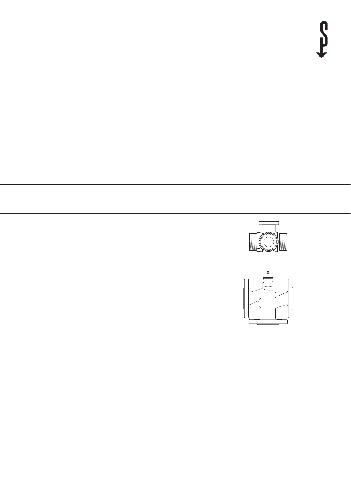
3-Wege-umschaltventil | 3-Way sWitching valve | soupape d’inversion à 3 voies | drieWeg-omschakelklep
» huv 1
» huv 2
» huv 65
» huv 80
Page 2
OPERATION
!
!
GENERAL INFORMATION
1. General information
This accessory installation guide is aimed at specialist technicians.
For installing the heat pump or similar items, see the additional
operating and installation instructions.
Please read
Read these instructions carefully before use and keep
them in a safe place. If you pass on the equipment to
another user, give them the instructions as well.
1.1 Explanation of symbols
Symbols in the documentation:
This documentation contains symbols and highlights. These have
the following meanings:
Beware of injury
Indication of possible risk of injury to the technician or
user, and possible damage to the device.
Beware of electrocution
Beware of burns and scalding
Beware of damage
Indicates a potentially dangerous situation which might
occur while installing or operating the device and could
damage the device or cause environmental or financial
harm.
Please read
Read these instructions carefully before use and keep
them in a safe place. If you pass on the equipment to
another user, give them the instructions as well.
2. Safety
2.2 Safety instructions
Observe the following safety instructions and regulations.
Heat pump systems and accessories may only be installed by a
recognised specialised company.
The qualified technician is responsible for observing all applicable
regulations during installation and commissioning.
Only operate the device when it is fully installed with all its safety
equipment.
Beware of electrocution
Switch off the power supply immediately if cables are
damaged. Make sure it is secured against being switched
on again unintentionally.
Beware of electrocution
Make sure all cable entries are fitted with the appropriate protection class.
Beware of burns and scalding
Before working on the system, let the pipes on the relevant section cool down as necessary and reduce the
system pressure to ambient pressure.
Beware of injury
The appliance may be used by children aged 8 and up
and persons with reduced physical, sensory or mental
capabilities or a lack of experience provided that they
are supervised or they have been instructed on how to
use the appliance safely and have understood the resulting risks. Children must never play with the appliance.
Children must never clean the appliance or perform user
maintenance unless they are supervised.
Beware of damage
The 3-way switching valve is designed for use in STIEBEL
ELTRON or Tecalor heat pump systems and may not be
used for applications outside the stated range, particularly in aircraft or other means of transport.
2.1 Proper use
The 3-way switching valve distributes and regulates the flow in
STIEBEL ELTRON or Tecalor heat pump systems. Any different or
extended use is considered improper, especially use with other
media to be heated. Proper use also includes observing the installation instructions. Only use the device for the purpose stated by
the manufacturer and do not make any modifications to it.
This appliance is designed for domestic use. It can be used safely
by untrained persons. The appliance can also be used in a nondomestic environment, e.g. in a small business, as long as it is
used in the same way.
10 | HUV 1/2/65/80
3. Device description
3.1 Overview of models and combination options
Model Order no.
HUV 1 247420
HUV 2 223391
HUV 65 227425
HUV 80 227426
3.2 Scope of delivery
- 3-way switching valve
- Servo drive
- 3 x counter screws G1
- 3 x counter screws G2
The servo drive is delivered already fitted to the 3-way switching
valve.
1
/2” x 1” (HUV 1 only)
3
/4“ x 2“ (HUV 2 only)
Page 3
OPERATION
HUV 65 | HUV 80
min. X
DEVICE DESCRIPTION
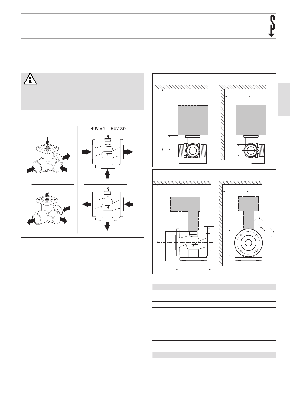
3.3 Function
The 3-way switching valve is controlled using a servo or
lift drive.
Note
As well as the flow direction A – AB and B – AB which
is marked with an arrow on the housing, the opposite
direction AB – A and AB – B is also permitted in STIEBEL
ELTRON or Tecalor heat pump systems.
Flow direction
HUV 1 | HUV 2
A
AB
A
B
B
AB
3.4 Dimensions, distances and connections
3.4.1 3-way switching valves
Dimensions and flanges for HUV 1 | 2
min. Y
min. X
H
D
L
Dimensions and flanges for HUV 65 | 80
min. Y
ENGLISH
B
C26_03_01_0995
A
AB
A
B
B
AB
HUV 1 | HUV 2 only: The servo drive is constantly regulated by a
control system and moves the ball of the 3-way switching valve,
that acts as a restrictor, to the position specified by the actuator
signal. The valve opens by turning clockwise and closes by turning
anticlockwise (factory setting).
HUV 65 | HUV 80 only: The lift drives are regulated by a 3-point
control system and move the closing element, which acts as a
mixer, to the opening position defined by the actuator signal.
C
C26_03_01_0998
HB
D
L
Dimensions HUV 1 HUV 2 HUV 65 HUV 80
L mm84.5 131,5 290 310
H mm46 56 100 110
B mm47.5 71.5 120 130
D DN 25
C mm– – 16 18
K mm– – 130 150
d mm– – 4 x 14 4 x 18
25 mm
(1 inch)
1
/
G1
2
DN 50
50 mm
(2 inches)
G23/
4
DN 65
160 mm
d
DN 80
190 mm
K
C26_03_01_0996
HUV 1/2/65/80 | 11
Distances*
X mm240 240 515 515
Y mm90 90 100 100
* Distances in relation to the centre of the valve
Page 4

OPERATION
25 103
HUV 1 | HUV 2
!
!
INSTALLATION
3.4.2 Servo drives
Dimensions HUV 1 | 2
(33)* (117)*
R65
Dimensions HUV 65 | 80
193
45
* Values in brackets are for HUV 1.
(177)*
134
160
150
98
84
(86)*
71
(93)*
4. Installation
4.1 Installation position
The 3-way switching valves can be installed either vertically or
horizontally.
Beware of damage
!
The 3-way switching valves may not be installed suspended, i.e. with the tappet facing down.
Permissible installation positions
90° 90°
C26_03_01_0997
4.2 Hydraulic connection
Beware of damage
The conditions in VDI 2035 regarding water quality must
be complied with. So that the 3-way switching valve controls the flow for a long time, we recommend the use of
contamination filters.
Beware of damage
Make sure the ball is correctly positioned in
the 3-way switching valve (note the mark on
the spindle).
D0000038083
Note
As well as the flow direction A – AB and B – AB which
is marked with an arrow on the housing, the opposite
direction AB – A and AB – B is also permitted in STIEBEL
ELTRON or Tecalor heat pump systems.
C26_03_01_0998
12 | HUV 1/2/65/80
A
A
AB
B
AB
B
A
B
A
B
AB
AB
26_03_01_0999
Page 5

INSTALLATION
!
!
MAINTENANCE
4.3 Electrical connection
Beware of electrocution
Always switch off the power supply before installation.
Make sure it is secured against being switched on again
unintentionally.
4.3.1 HUV 1 | HUV 2
Connection diagram (open/closed control)
L1
N
1
2 3
Y2
Beware of damage
Only the factory-set open/close setting may be used in
STIEBEL ELTRON or Tecalor heat pump systems.
The 3-way diverter valve is factory-set to flow direction B - AB.
To change the flow direction to A - AB, change the covered rotary
selector from Y2 to Y1.
4.3.2 HUV 65 | HUV 80
Connection diagram (open/closed control)
N L
1 2 3
a a
bb
1 blue
2 brown
3 white
5. Maintenance
26_03_01_1784
The 3-way switching valves with integrated servo drive require no
maintenance. They do not contain any parts that can be replaced
or repaired by the user.
Beware of electrocution
Always switch off the power supply before maintenance.
Make sure it is secured against being switched on again
unintentionally.
a
b
ENGLISH
D0000043142
Beware of burns and scalding
Let the pipes on the relevant section cool down as necessary and reduce the system pressure to ambient pressure.
Beware of damage
Switch off the pumps for the relevant pipe section and
close the associated shut-off valves.
The system may only be started up again once the 3-way switching
valves with integrated servo drive have been correctly fitted and
the pipes correctly filled.
26_03_01_1783
HUV 1/2/65/80 | 13
Page 6

INSTALLATION
TECHNICAL DATA
6. Technical data
HUV 1 HUV 2 HUV 65 HUV 80
227420 223391 227425 227426
Sound data
Sound power level dB(A) 35 45 45 35
Application limits
Max. permissible pressure MPa 276 276 60 60
Hydraulic data
Flow capacity m3/h 26 49 58 90
Differential pressure Δp
Closing pressure Δp
Electrical data
Rated voltage V 230 230 230 230
Frequency Hz 50/60 50/60 50/60 50/60
Power consumption, operational W 1.5 2.5 2 2
Power consumption, idle W 0.4 0.4 1 1
Power consumption, sizing VA 4.5 4.5
Versions
Power cable * * * *
Power cable length approx. mm 1000 1000 1000 1000
Operating mode parallel parallel parallel parallel
Safety category II, double insulated II, double insulated II, double insulated II, double insulated
IP rating IP54 IP54 IP54 IP54
Dimensions
Length mm 84.5 131.5 290 310
Weights
Weight kg 1.65 4.8 16.3 22.5
Values
Permissible medium H2O H2O H2O H2O
Permissible medium 2 H2O glycol S H2O glycol S H2O glycol S H2O glycol S
Maximum mixing ratio % 50 50 50 50
Permissible additive medium glycol glycol glycol glycol
Max. operating temperature °C 100 100 100 100
Flow rate, control path A-AB (VDi 2173) n(gL) 3.9 3.9 3 3
Flow rate, bypass B-BA (linear) kvs * 0.7 kvs * 0.7
Leakage rate bypass B-AB kvs * 0.01 kvs * 0.01 kvs * 0.01 kvs * 0.01
Leakage rate, control path A-AB (B0.1 Din 3230) air bubble tight air bubble tight
Pivoting bracket ° 90 90
Angle of rotation, working area ° 15...90 15...90
Connecting cable, cable cross-section mm
Torque Nm min. 5 min. 20
Runtime 90s / 90° 90s / 90° 7.5 s/mm (18mm) 7.5 s/mm (18mm)
Ambient temperature °C 0...50 0...50 0...50 0...50
Permissible relative humidity (non-condensing) % 95 95 95 95
max
s
kPa 100 350 140 80
kPa 1000 1400 140 80
2
3 x 0.75 3 x 0.75
14 | HUV 1/2/65/80
Page 7

Warranty | EnvironmEnt and rEcycling
Warranty
The warranty conditions of our German companies do not
apply to appliances acquired outside of Germany. In countries
where our subsidiaries sell our products, it is increasingly the
case that warranties can only be issued by those subsidiaries.
Such warranties are only granted if the subsidiary has issued
its own terms of warranty. No other warranty will be granted.
We shall not provide any warranty for appliances acquired in
countries where we have no subsidiary to sell our products.
This will not aect warranties issued by any importers.
Environment and recycling
We would ask you to help protect the environment. After use,
dispose of the various materials in accordance with national
regulations.
ENGLISH
HUV 1/2/65/80 | 15
Page 8

STIEBEL ELTRON GmbH & Co. KG
Dr.-Stiebel-Str. 33 | 37603 Holzminden
Tel. 05531 702-0 | Fax 05531 702-480
info@stiebel-eltron.de
www.stiebel-eltron.de
tecalor GmbH
Fürstenberger Str. 77 | 37603 Holzminden
Tel. 05531 99068-700 | Fax 05531 99068-712
info@tecalor.de
www.tecalor.de
4<AMHCMN=ifdahi>
Irrtum und technische Änderungen vorbehalten! | Subject to errors and technical changes! | Sous réserve d‘erreurs et de modifications techniques! | Onder voorbehoud
van vergissingen en technische wijzigingen! | Salvo error o modificación técnica! | Rätt till misstag och tekniska ändringar förbehålls! | Excepto erro ou alteração técnica |
Zastrzeżone zmiany techniczne i ewentualne błędy | Omyly a technické změny jsou vyhrazeny! | A muszaki változtatások és tévedések jogát fenntar tjuk! | Отсутствие ошибок
не гарантируется. Возможны технические изменения. | Chyby a technické zmeny sú vyhradené! Stand 8843
A 285307-37449-8938
 Loading...