

Page 1
BEDIENUNG UND INSTALLATION
OPERATION AND INSTALLATION
UTILISATION ET INSTALLATION
BEDIENING EN INSTALLATIE
USO E INSTALLAZIONE
Integral-Speicher| Integral cylinder| Ballon intégral| Combiboiler| Caldaia
integrale
» HSBC 200
» HSBC 200 S
Page 2

30 | HSBC www.stiebel-eltron.com
CONTENTS | SPECIAL INFORMATION
SPECIAL INFORMATION
- The appliance may be used by children over
8years of age and persons with reduced physical, sensory or mental capabilities or a lack of
experience and expertise, provided that they are
supervised or they have been instructed on how
to use the appliance safely and have understood
the potential risks. Children must never play with
the appliance. Children must never clean the appliance or perform user maintenance unless they
are supervised.
- The connection to the power supply must be in
the form of a permanent connection. Ensure the
appliance can be separated from the power supply by an isolator that disconnects all poles with
at least 3mm contact separation.
- Observe all applicable national and regional regulations and instructions.
- Observe minimum distances (see chapter "Installation/ Preparations/ Installation site").
- Only a qualified contractor should carry out installation, commissioning, maintenance and repair of the appliance.
DHW cylinder
- Drain the appliance as described in chapter "Installation/ Maintenance/ Draining the DHW
cylinder".
- Observe the maximum permissible pressure (see
chapter "Installation/ Specification/ Data table").
- The appliance is pressurised. During the heat-up
process, expansion water will drip from the safety
valve.
- Regularly activate the safety valve to prevent
it from becoming blocked, e.g. by limescale
deposits.
- The safety valve drainage aperture must remain
open to atmosphere.
SPECIAL INFORMATION
OPERATION
1. General information ��������������������������������������� 31
1.1 Relevant documents�������������������������������������������� 31
1.2 Safety instructions ����������������������������������������������31
1.3 Other symbols in this documentation ���������������������� 31
1.4 Information on the appliance �������������������������������� 31
1.5 Units of measurement ����������������������������������������� 31
2. Safety �������������������������������������������������������� 32
2.1 Intended use ����������������������������������������������������� 32
2.2 General safety instructions �����������������������������������32
2.3 Test symbols ����������������������������������������������������� 32
3. Appliance compatibility ����������������������������������� 32
4. Appliance description ������������������������������������� 32
5. Settings ����������������������������������������������������� 33
6. Cleaning, care and maintenance ������������������������� 33
7. Troubleshooting �������������������������������������������� 33
INSTALLATION
8. Safety �������������������������������������������������������� 34
8.1 General safety instructions �����������������������������������34
8.2 Instructions, standards and regulations ������������������� 34
9. Appliance description ������������������������������������� 34
9.1 Standard delivery ����������������������������������������������� 34
9.2 Accessories ������������������������������������������������������� 34
10. Preparations ������������������������������������������������ 34
10.1 Installation site �������������������������������������������������� 34
10.2 Transport and handling ���������������������������������������35
11. Installation �������������������������������������������������� 37
11.1 Positioning the appliance �������������������������������������37
11.2 Heating water connection and safety valve ���������������37
11.3 DHW connection and safety assembly ���������������������� 39
11.4 Filling the system ����������������������������������������������� 40
11.5 Venting the appliance ������������������������������������������ 41
12. Power supply ����������������������������������������������� 41
12.1 Electric emergency/booster heater and control voltage 42
12.2 Low voltage, BUS cable ���������������������������������������� 43
12.3 Sensor installation ����������������������������������������������44
12.4 Remote control �������������������������������������������������� 45
13. Commissioning ��������������������������������������������� 45
13.1 Checks before commissioning the heat pump manager 45
13.2 Commissioning the heat pump manager ������������������ 46
13.3 Appliance handover �������������������������������������������� 46
14. Appliance shutdown ��������������������������������������� 46
15. Maintenance ������������������������������������������������ 46
16. Specification ������������������������������������������������ 48
16.1 Dimensions and connections ��������������������������������� 48
16.2 Wiring diagram for HSBC 200 �������������������������������� 50
16.3 Wiring diagram for HSBC 200 S ������������������������������ 52
16.4 Data table �������������������������������������������������������� 55
16.5 Details on energy consumption ������������������������������ 56
GUARANTEE | ENVIRONMENT AND RECYCLING
Page 3
OPERATION
General information
www.stiebel-eltron.com HSBC | 31
ENGLISH
OPERATION
1. General information
The chapters "Special information" and "Operation" are intended
for both users and qualified contractors.
The chapter "Installation" is intended for qualified contractors.
Note
Read these instructions carefully before using the appliance and retain them for future reference.
Pass on the instructions to a new user if required.
1.1 Relevant documents
Operating and installation instructions for the WPM3
heat pump manager
Operating and installation instructions for the connected
heat pump
Operating and installation instructions for all other sys-
tem components
1.2 Safety instructions
1.2.1 Structure of safety instructions
!
KEYWORD Type of risk
Here, possible consequences are listed that may result
from failure to observe the safety instructions.
Steps to prevent the risk are listed.
1.2.2 Symbols, type of risk
Symbol Type of risk
Injury
Electrocution
Burns
(burns, scalding)
1.2.3 Keywords
KEYWORD Meaning
DANGER Failure to observe this information will result in serious
injury or death.
WARNING Failure to observe this information may result in serious
injury or death.
CAUTION Failure to observe this information may result in non-seri-
ous or minor injury.
1.3 Other symbols in this documentation
Note
General information is identified by the adjacent symbol.
Read these texts carefully.
Symbol Meaning
Material losses
(appliance damage, consequential losses and environmental pollution)
Appliance disposal
This symbol indicates that you have to do something. The ac-
tion you need to take is described step by step.
These symbols show you the software menu level (in
this example level3).
1.4 Information on the appliance
Connections
Symbol Meaning
Inlet/ intake
Red arrow: Hot
Blue arrow: Cold
Green arrow: Neutral
Drain/ outlet
Red arrow: Hot
Blue arrow: Cold
Green arrow: Neutral
Domestic hot water
DHW circulation
Heat pump
Central heating
1.5 Units of measurement
Note
All measurements are given in mm unless stated otherwise.
!
!
Page 4
OPERATION
Safety
32 | HSBC www.stiebel-eltron.com
2. Safety
2.1 Intended use
This appliance is intended to be used for heating and cooling
interiors (area cooling 18°C/ 23°C) and for DHW heating.
The appliance is intended for domestic use. It can be used safely
by untrained persons. The appliance can also be used in non-domestic environments, e.g. in small businesses, as long as it is
used in the same way.
Any other use beyond that described shall be deemed inappropriate. Observation of these instructions and of the instructions
for any accessories used is also part of the correct use of this
appliance.
2.2 General safety instructions
WARNING Burns
There is a risk of scalding at outlet temperatures in excess of 43 °C.
!
WARNING Injury
The appliance may be used by children over 8years of
age and persons with reduced physical, sensory or mental capabilities or a lack of experience and expertise,
provided that they are supervised or they have been
instructed on how to use the appliance safely and have
understood the potential risks. Children must never play
with the appliance. Children must never clean the appliance or perform user maintenance unless they are
supervised.
!
WARNING Injury
For safety reasons, only operate the appliance with the
front casing closed.
Note
The DHW cylinder is under mains pressure. During the
heat-up process, expansion water will drip from the safety valve.
If water continues to drip when heating is complet-
ed, please inform your qualified contractor.
2.3 Test symbols
See type plate on the appliance.
3. Appliance compatibility
The appliance can be operated in conjunction with the following
air | water heat pumps:
- WPL 13 E, WPL 13 (S) basic
- WPL 10 AC (S)
- WPL 15-25AC (S), WPL 15-25 A (S)
- WPL 08-28 (S) Trend
4. Appliance description
The buffer cylinder and DHW cylinder with indirect coil are arranged one above the other and can be separated for easier handling.
The appliance has a plastic jacket with foam insulation and is
equipped with a removable front casing. The appliance is connected hydraulically and electrically to the heat pump. All hydraulic
connections are made at the top.
In addition to the DHW cylinder and the buffer cylinder, further
system components are integrated:
- Heat pump manager
- Cylinder primary pump
- Highly efficient circulation pump for a heating circuit without
mixer
- Multifunction assembly with safety valve and 3-way diverter
valve
- Emergency/booster heater for mono energetic operation
DHW cylinder
The steel cylinder is coated on the inside with special direct enamel and is equipped with a signal anode. The anode with consumption indicator protects the cylinder interior from corrosion.
The heating water heated by the heat pump is pumped through an
indirect coil inside the DHW cylinder. The heat channelled through
the indirect coil is thus transferred to the domestic hot water. The
integral heat pump manager regulates the DHW heating to the
required temperature.
Buffer cylinder
The steel cylinder provides hydraulic separation between the flow
rates of heat pump and heating circuit. The heating water heated
by the heat pump is transferred into the buffer cylinder by the
cylinder charging pump. When a demand is issued, the integral
heating circuit pump delivers the heating water to the heating
circuit.
Heat pump manager (WPM)
The system is controlled by means of the integral heat pump manager.
The heat pump manager is suitable for the control of a direct
heating circuit and a heating circuit with mixer.
You can set the times and temperatures for heating operation and
heating DHW. Remote controls for controlling the direct heating
circuit and the heating circuit with mixer are available as accessories.
For detailed information, see the enclosed operating and installation instructions for the WPM3 heat pump manager.
Multifunction assembly (MFG)
The multifunction assembly switches between heating circuit and
DHW heating.
Page 5
OPERATION
Settings
www.stiebel-eltron.com HSBC | 33
ENGLISH
5. Settings
!
Material losses
The system's active frost protection is not guaranteed if
the power supply is interrupted.
Never interrupt the power supply even outside the
heating season.
Note
The heat pump manager has an automatic summer/winter changeover so you can leave the system switched on
in summer.
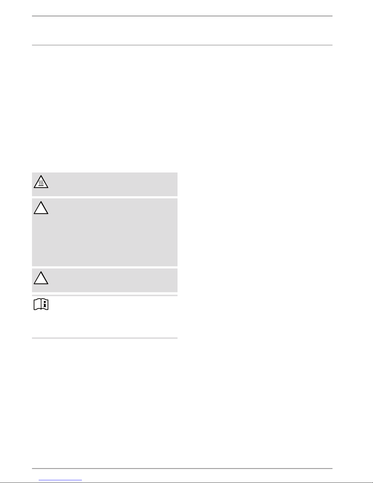
The system is controlled by means of the integral heat pump
manager. Please observe the heat pump manager operating and
installation instructions.
OKMENU
D0000064711
6. Cleaning, care and maintenance
Have the electrical safety of the appliance and the function
of the safety assembly regularly checked by a qualified
contractor.
Never use abrasive or corrosive cleaning agents. A damp
cloth is sufficient for cleaning the appliance.
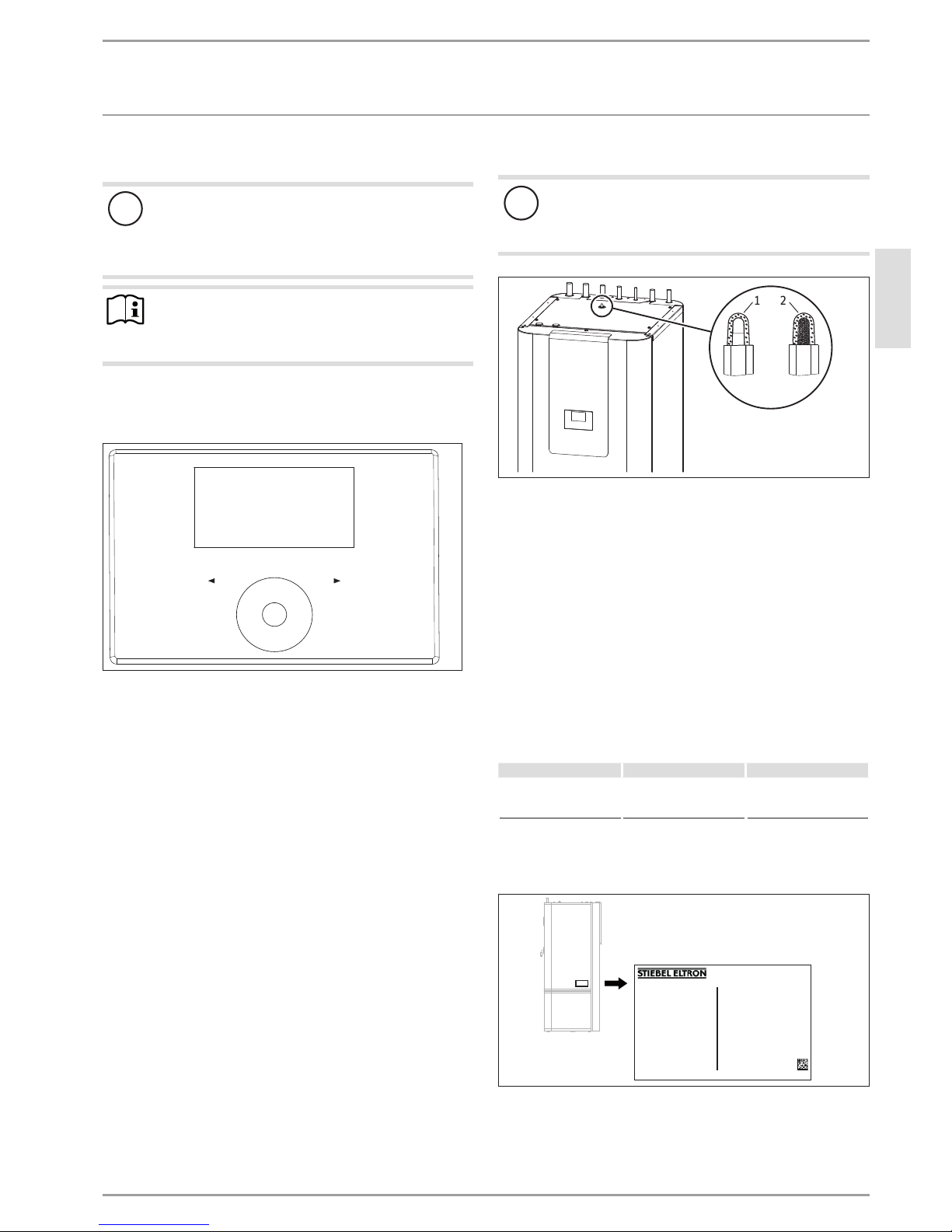
Signal anode with consumption indicator
!
Material losses
If the consumption indicator changes colour from white
to red, have the signal anode checked by a qualified contractor and if necessary replaced.
1 2
D0000055608
1 White = Anode OK
2 Red = Requires checking by qualified contractor
Scaling
Almost every type of water will deposit limescale at high temperatures. This settles inside the appliance and affects both the
performance and service life. A qualified contractor who knows
the local water quality will tell you when the next service is due.
Check the taps regularly. Limescale deposits at the tap out-
lets can be removed using commercially available descaling
agents.
Regularly activate the safety valve to prevent it from becom-
ing blocked, e.g. by limescale deposits.
7. Troubleshooting
Problem Cause Remedy
The water does not heat
up. The heating does not
work.
There is no power.
Check the fuses/MCBs in
your distribution board.
If you cannot remedy the fault, contact your qualified contractor.
To facilitate and speed up your request, provide the number from
the type plate (000000-0000-000000).
No.:
000000-0000-000000
Made in Germany
D0000056320
Page 6
INSTALLATION
Safety
34 | HSBC www.stiebel-eltron.com
INSTALLATION
8. Safety
Only a qualified contractor should carry out installation, commissioning, maintenance and repair of the appliance.
8.1 General safety instructions
We guarantee trouble-free function and operational reliability only
if original accessories and spare parts intended for the appliance
are used.
8.2 Instructions, standards and regulations
Note
Observe all applicable national and regional regulations
and instructions.
9. Appliance description
9.1 Standard delivery
The following are delivered with the appliance:
- Operating and installation instructions for the WPM3 heat
pump manager
- Outside temperature sensor AFS 2
- 4 adjustable feet
- Drain hose
9.2 Accessories
Required accessories
Safety assemblies and pressure reducing valves are available
to suit the prevailing supply pressure. These type-tested safety
assemblies protect the appliance against impermissible excess
pressure.
Required for area cooling:
- Temperature sensor TF 6
- FEK remote control
Additional accessories
- Pump assembly for a heating circuit with mixer HSBC-HKM
- Remote control for heating operation
- High limit safety cut-out STB-FB
- Pressure hoses
- Water softening fitting HZEA
10. Preparations
10.1 Installation site
!
Material losses
Never install the appliance in wet rooms.
Install the appliance near the draw-off point in a dry room free
from the risk of frost. To reduce line losses, keep the distance short
between the appliance and the heat pump.
Ensure the floor has sufficient load-bearing capacity and evenness
(for weight, see chapter "Specification/ Data table").
The room must not be subject to a risk of explosions arising from
dust, gases or vapours.
If you are installing the appliance in a boiler room together with
other heating equipment, ensure that the operation of other heating equipment will not be impaired.
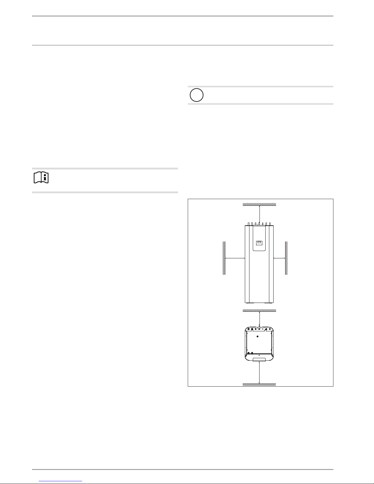
Minimum clearances
≥500 ≥100
≥100 ≥400
≥800
D0000055505
The minimum side clearances can be swapped between left and
right.
Page 7
INSTALLATION
Preparations
www.stiebel-eltron.com HSBC | 35
ENGLISH
10.2 Transport and handling
!
Material losses
Store and transport the appliance at temperatures between -20°C to +60°C.
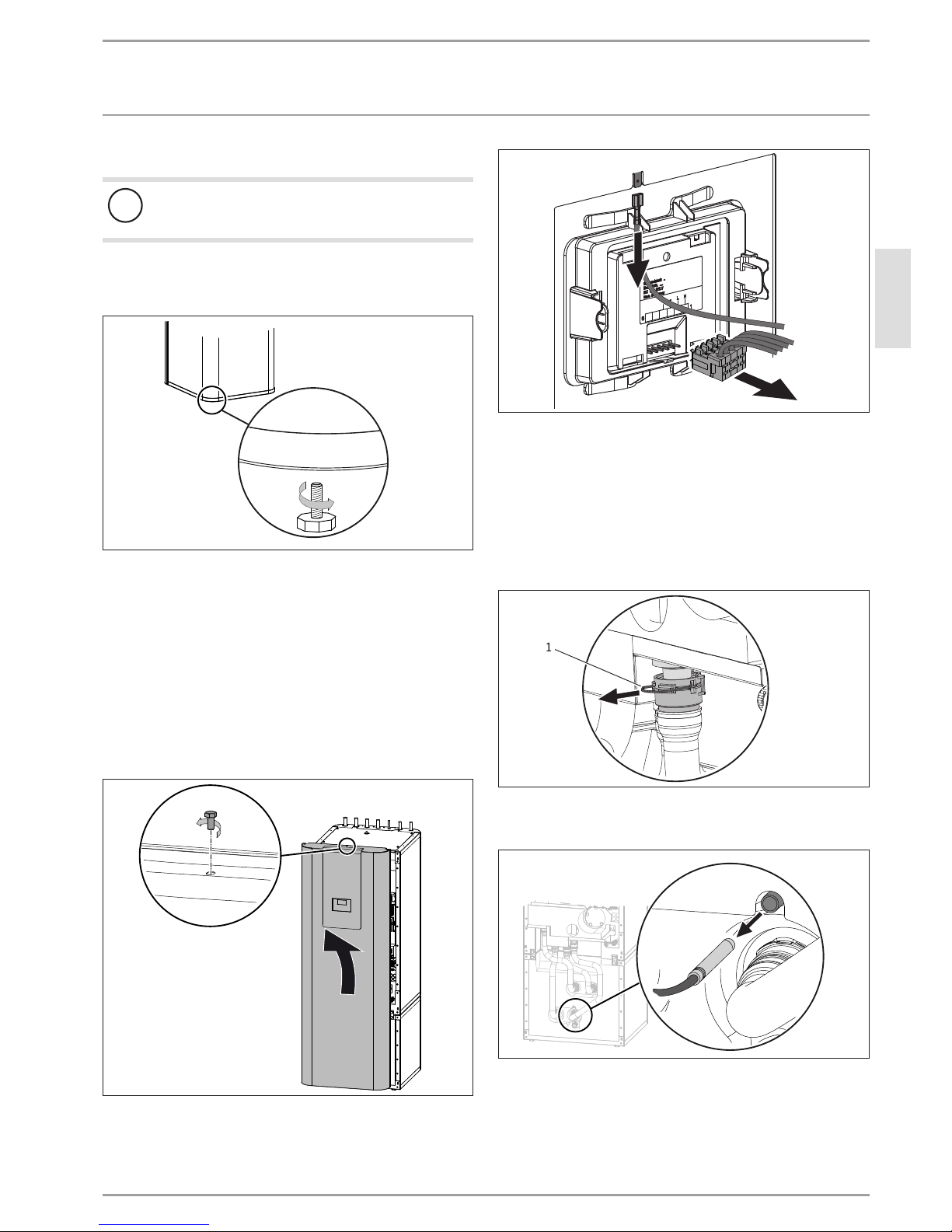
Handling
Undo the 4screws from the non-returnable pallet.
D0000055519
Tilt the appliance and wind the 4adjustable feet into the
appliance.
Lift the appliance off the pallet. For a better hold during
transport, use the recessed grips on the underside and rear
of the appliance.
If narrow doors or hallways hinder handling, you can separate
the upper and lower sections of the appliance as described in the
following chapters.
10.2.1 Removing/ fitting the front casing
Removing the front casing
D0000055619
Remove the screw at the top in the middle of the appliance.
Unhook the front casing towards the top.
D0000055620
Detach the plug of the electronic assembly for operation and
the earth connection from the front fascia.
Fitting the front casing
Fit the front casing in reverse order.
10.2.2 Separating/ joining the appliance sections
Separating the appliance sections
D0000055689
1
Disconnect the push-fit connectors of the 4hydraulic connec-
tions. To do this, pull the spring clips fully out with a screwdriver. Pull the hydraulic connectors off downwards.
D0000055874
Pull out the sensor at the buffer cylinder.
Page 8
INSTALLATION
Preparations
36 | HSBC www.stiebel-eltron.com
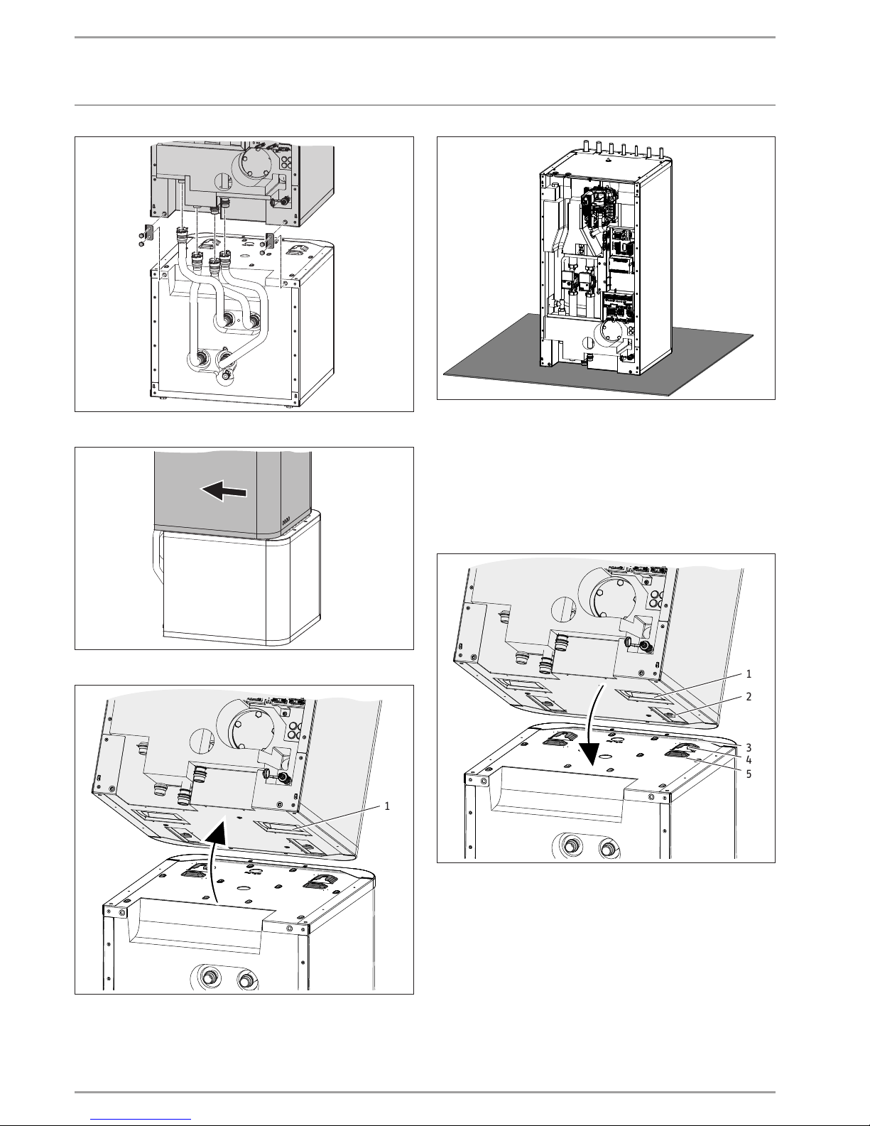
D0000055685
Release the 4screws on the tabs at the front of the appliance.
D0000057295
Pull the upper section of the appliance towards the front.
D0000057294
1
1 Recessed grip
Tip the upper section of the appliance backwards. For a
better hold during transport, use the recessed grips on the
underside and rear of the appliance.
D0000057298
Place the upper section of the appliance on a base to prevent
damage.
Joining appliance sections
Rejoin the appliance sections in reverse order.
The positioning aids and the dotted line marking provide assis-
tance when positioning and inserting the upper appliance section
into the guide groove on the lower section:
D0000055687
1
2
4
3
5
1 Recessed grip
2 Guide pin
3 Dotted line (perforation in the panel)
4 Guide groove
5 Positioning aid
Page 9
INSTALLATION
Installation
www.stiebel-eltron.com HSBC | 37
ENGLISH
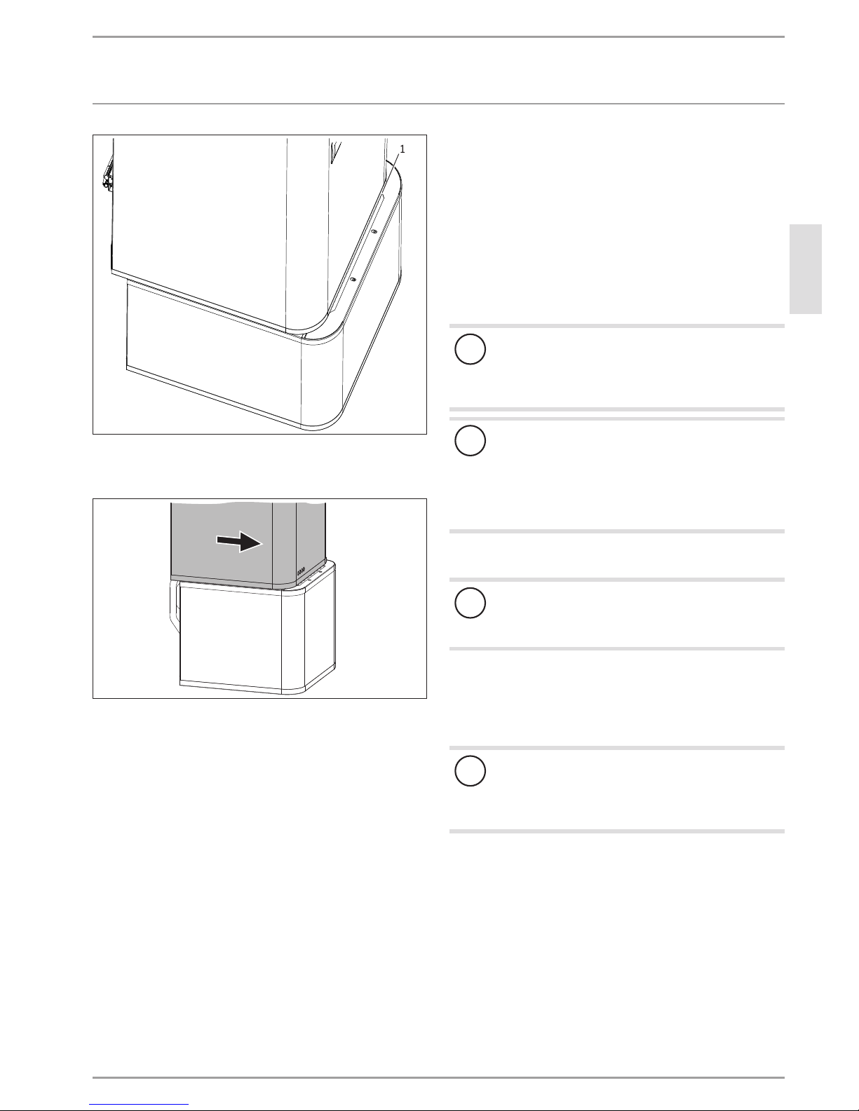
1
D0000057300
1 Dotted line (perforation in the panel)
Place the upper appliance section onto the lower appliance
section along the dotted line.
D0000055688
Slide the upper appliance section to the back until it is flush
with the lower appliance section. If the appliance sections
are joined correctly, the final position is determined by the
guide groove and guide pin.
Secure the tabs on the appliance front.
Insert the sensor at the buffer cylinder.
Connect the push-fit connectors of the 4hydraulic connec-
tions. Ensure that the spring clips click into place.
11. Installation
11.1 Positioning the appliance
When positioning the appliance, observe minimum clearanc-
es (see chapter "Preparations/ Installation site").
Use the adjustable feet to compensate for any unevenness in
the floor.
11.2 Heating water connection and safety valve
11.2.1 Safety instructions
!
Material losses
The heating system to which the appliance is connected
must be installed by a qualified contractor in accordance with the water installation drawings in the technical
guides.
!
Material losses
When fitting additional shut-off valves, install a further
safety valve in an accessible location on the heat generator itself or in the flow line in close proximity to the
heat generator.
There must be no shut-off valve between the heat generator and the safety valve.
Oxygen diffusion
!
Material losses
Avoid open vented heating systems and underfloor heating systems with plastic pipes which are permeable to
oxygen.
In underfloor heating systems with plastic pipes that are permeable to oxygen and in open vented heating systems, oxygen
diffusion may lead to corrosion on the steel components of the
heating system (e.g.on the indirect coil of the DHW cylinder, on
buffer cylinders, steel radiators or steel pipes).
!
Material losses
The products of corrosion (e.g.rusty sludge) can settle in the heating system components, which may result in a lower output or fault shutdowns due to reduced
cross-sections.
Page 10

INSTALLATION
Installation
38 | HSBC www.stiebel-eltron.com
Supply lines
The maximum permissible line length between the appli-
ance and the heat pump will vary, depending on the version
of the heating system (pressure drop). As a standard value,
assume a maximum line length of 10m and a pipe diameter
of 22-28mm.
Protect the flow and return lines against frost with sufficient
thermal insulation.
Also protect all supply lines/cables against humidity, damage
and UV radiation by means of a conduit.
Pressure hoses against structure-borne sound transmission:
The appliance and the heat pump are connected to each other
hydraulically via pipes carrying heating water. To reduce the trans-
mission of structure-borne sound on the water side, connect the
appliance to the heat pump with pressure hoses (not required for
WPL 15-25 A).
Pressure differential:
If the available external pressure difference is exceeded, the pres-
sure drop in the heating system could result in a reduced heating
output.
When sizing the pipes, ensure that the available external
pressure differential is not exceeded (see chapter "Specification/ Data table").
When calculating the pressure drop, take account of the flow
and return lines and the pressure drop of the heat pump.
The pressure drop must be covered by the available pressure
differential.
11.2.2 Fitting the pump assembly (accessory) if required
To extend the appliance with a heating circuit with mixer, you can
install pump assembly HSBC-HKM (available as accessory).
- Insulated connection pipes
- Pre-fitted contact thermostat
- Heating circuit pump
- 3-way mixer with servomotor
- 2 plastic fixing aids
- Supplement, HSBC-HKM installation and electrical connection
- Operating and installation instructions for the heating circuit
pump
D0000056342
1
2
4
3
1 Dummy plug
2 Union nut (mixed heating return connection)
3 Plastic fixing aid
4 Tee (mixed heating flow connection)
Replace the dummy plugs with the enclosed plastic fixing
aids at the mixed heating flow and return connections.
Remove the union nut at the mixed heating return
connection.
Remove the tee at the mixed heating flow connection of the
buffer cylinder.
Fit the pump assembly connection pipes.
Observe the parameter settings in menu "SETTINGS/ HEATING/
HEATING CIRCUIT 2" in the enclosed operating and installation
instructions for the heat pump manager.
Page 11

INSTALLATION
Installation
www.stiebel-eltron.com HSBC | 39
ENGLISH
11.2.3 Connection
Installation example:
1
2
D0000055506
1 Pipes carrying heating water
2 Pressure hose (available as accessory)
Thoroughly flush the pipes before connecting the heat pump.
Foreign bodies (e.g. welding pearls, rust, sand, sealant, etc.)
can impair the operational reliability of the heat pump.
Install the heating water pipes (see chapter "Specification/
Dimensions and connections").
Safety valve
1
3
2
D0000055520
1 Drain hose
2 Fasteners (not part of the standard delivery)
3 Drain (not part of the standard delivery)
Size the drain hose so that water can drain off unimpeded
when the safety valve is fully opened.
Ensure that the safety valve drain hose is open to the outside.
Lay the safety valve drain hose with a constant fall to the
drain.
Secure the drain hose to prevent any hose movement while
water is discharged.
11.3 DHW connection and safety assembly
11.3.1 Safety instructions
!
Material losses
The maximum permissible pressure must not be exceeded (see chapter "Specification/ Data table").
!
Material losses
Operate the appliance only with pressure-tested taps.
Cold water line
Galvanised steel, stainless steel, copper and plastic are approved
materials.
!
Material losses
A safety valve is required.
DHW line, DHW circulation line
Stainless steel, copper and plastic are approved materials.
11.3.2 Installing the DHW circulation line, if applicable
A DHW circulation line with external DHW circulation pump can be
fitted to the DHW circulation connection (see chapter "Specification
/ Dimensions and connections").
Remove the sealing cap from the DHW circulation connection
(see chapter "Specification / Dimensions and connections").
Connect the DHW circulation line.
D0000060804
Open the shut-off valve for the DHW circulation.
Page 12

INSTALLATION
Installation
40 | HSBC www.stiebel-eltron.com
11.3.3 DHW connection and safety assembly
Flush the pipes thoroughly.
Install the DHW outlet line and the cold water inlet line (see
chapter "Specification/ Dimensions and connections").
Install a type-tested safety valve in the cold water inlet line.
Please note that, depending on the supply pressure, you may
also need a pressure reducing valve.
Size the drain pipe so that water can drain off unimpeded
when the safety valve is fully opened.
The safety valve drainage aperture must remain open to
atmosphere.
Install the safety valve drain pipe with a constant fall to the
drain.
11.4 Filling the system
Heating circuit water quality
Carry out a fill water analysis before filling the system. This analysis may, for example, be requested by the relevant water supply
utility.
To avoid damage as a result of scaling, it may be necessary to
soften or desalinate the fill water. The fill water limits specified
in chapter "Specification/ Data table" must always be observed.
Recheck these limits 8-12weeks after commissioning and
during the annual system service.
Note
With a conductivity >1000μS/cm, desalination treatment
is recommended in order to avoid corrosion.
Note
If you treat the fill water with inhibitors or additives, the
same limits apply as for desalination.
Note
Suitable appliances for water softening, as well as for
filling and flushing heating systems, can be obtained via
trade suppliers.
!
Material losses
Never switch on the power before filling the system.
11.4.1 Filling the heating system
In the delivered condition, the 3-way diverter valve of the multifunction assembly is in its centre position, so that the heating
circuit and the heat exchanger for DHW heating are filled evenly.
When power is switched on, the 3-way diverter valve automatically
switches to heating mode.
To fill or drain the system later, you must first place the 3-way
diverter valve into its centre position.
To set the heat pump manager:
With the MENU key, call up the main menu.
Select the menu or value and confirm with OK:
DIAGNOSIS
RELAY TEST SYSTEM
DRAIN HYD
D0000055788
Fill the heating system via the drain valve.
Vent the pipework.
11.4.2 DHW cylinder filling
Fill the DHW cylinder via the cold water connection.
Open all downstream draw-off valves until the appliance is
full and the pipework is free of air.
Adjust the flow rate. For this, observe the maximum permis-
sible flow rate with a fully opened tap (see chapter "Specification/ Data table"). If necessary reduce the flow rate at the
butterfly valve of the safety assembly.
Carry out a tightness check.
Check the safety valve.
Page 13

INSTALLATION
Power supply
www.stiebel-eltron.com HSBC | 41
ENGLISH
11.5 Venting the appliance
To ventilate, temporarily open the quick-action air vent valve
in the multifunction assembly.
D0000055606
21
1 PCB
2 Quick-action air vent valve
!
Material losses
The air vent in the knurled cap of the quick-action air
vent valve must not point towards the multifunction assembly PCB.
Turn the air vent in the direction shown in the fol-
lowing diagram.
D0000055605
!
Material losses
Close the quick-action air vent valve again after venting.
12. Power supply
WARNING Electrocution
Carry out all electrical connection and installation work
in accordance with relevant regulations.
Before any work on the appliance, disconnect all poles
from the power supply.
WARNING Electrocution
Only use a permanent connection to the power supply.
Ensure the appliance can be separated from the power
supply by an isolator that disconnects all poles with at
least 3mm contact separation. This requirement can be
met with contactors, circuit breakers, fuses/MCBs, etc.
!
Material losses
Provide separate fuses for the two power circuits of the
appliance and the control unit.
!
Material losses
Provide separate fuses/MCBs for the two power circuits,
i.e. for the compressor and the electricemergency/booster heater circuits.
!
Material losses
Observe the type plate. The specified voltage must match
the mains voltage.
Note
You must have permission to connect the appliance from
the relevant power supply utility.
The terminal box of the appliance is located behind the front casing
(see chapter "Preparations/ Transport and handling/ Removing/
fitting the front casing").
D0000055594
Route all power cables and sensor leads into the appliance
through the cable entry.
Connect the power cables and sensor leads as detailed
below.
Page 14

INSTALLATION
Power supply
42 | HSBC www.stiebel-eltron.com
Install cables with the following cross-sections in accordance with
the respective fuse rating:
MCB/fuse
rating
Assignment Cable cross-section
B 16 A
Electric emergency/
booster heater
(DHC)
Three-phase
2.5mm²
1.5mm² with only two live wires, routing according to applicable regulations
B 16 A
Electric emergency/
booster heater
(DHC)
1 phase
2.5mm²
1.5mm² when routing a multi-core
cable on a wall or in an electrical conduit on a wall
B 16 A Control 1.5 mm²
12.1 Electric emergency/booster heater and control
voltage
Appliance
function
Effect of the electric emergency/booster
heater
Mono energetic
operation
If the heat pump undershoots the dual mode point, the
electric emergency/booster heater safeguards both the
heating operation and the delivery of high DHW temperatures.
Emergency mode Should the heat pump suffer a fault that prevents its con-
tinued operation, the heating output will be covered by
the electric emergency/booster heater.
HSBC 200: Electrical connection three-phase
D0000055646
X3 Electric emergency/booster heater (DHC)
Connected load Terminal assignment
2.9 kW PE N L1
5.9 kW PE N L2 L1
8.8 kW PE N L3 L2 L1
Connect the electrical emergency/booster heater with the
desired rating as detailed in the table.
HSBC 200 S: Electrical connection single phase
D0000056876
X3 Electric emergency/booster heater (DHC)
Connected
load
Cable
cross-section
Terminal assignment
2.9 kW 2.5mm² PE N L
5.9 kW
2.5mm² PE N L
2.5mm² PE N L
Connect the cables for the electrical emergency/booster
heater with the desired rating as in the table.
Control voltage
!
Material losses
Only connect energy efficient circulation pumps ap-
proved by us to the pump connections.
X4 Terminals, external control
EVU Enable signal
2WE Heat source 2 (floating contact)
2WE Heat source 2 (floating contact)
Kue/Solar Output, cooling/ solar circuit pump
Zirk/
2WE WW
DHW circulation pump (floating contact, function available as optional extension)/
heat source 2 for DHW (floating contact)
Page 15

INSTALLATION
Power supply
www.stiebel-eltron.com HSBC | 43
ENGLISH
12.2 Low voltage, BUS cable
D0000055645
X2.1 Terminals, external low voltage
T(Puf) Temperature sensor, buffer cylinder (function part of
the standard delivery)
T(WW) Temperature sensor, DHW (function part of the stand-
ard delivery)
T(Kue/WW) For cooling: flow sensor/
For solar connection: lower DHW sensor
T(2WE) Temperature sensor heat source 2
X2.2 Terminals, external low voltage
T(KOLL) Collector sensor
T(A) Outside temperature sensor (function part of the
standard delivery)
T(MK) Mixer circuit temperature sensor (function available as
optional extension)
Fernb. FE 7 remote control (function available as optional
extension)
X5 CAN BUS terminal
+ (only in conjunction with FEK)
⊥
Ground
L Low
H High
Connecting BUS cables
!
Material losses
Bus cables, power cables and sensor leads must be installed separately.
Install a J-Y (St) 2 x 2 x 0.8mm² cable as bus to the heat
pump.
A3
A2
A1
1 2 3 4
H L
T
+
1 2 3 4
X5
D0000056307
A1 WPM 3 heat pump manager
A2 Programming unit
A3 Heat pump
Page 16

INSTALLATION
Power supply
44 | HSBC www.stiebel-eltron.com
12.3 Sensor installation
12.3.1 Outside temperature sensor AFS 2
The outside temperature sensors have a significant influence on
the function of your heating system. Therefore ensure that the
outside temperature sensors are correctly positioned and well
insulated.
26�03�21 �0052
- Install the outside temperature sensor on a north or
north-eastern wall.
- Ensure that the outside temperature sensor is freely exposed
to the elements but not placed in direct sunlight.
- Never mount the outside temperature sensor above windows, doors or air ducts.
- Observe the following minimum clearances: 2.5m above the
ground and 1m to the side of windows and doors
Installation
Remove the cover.
Secure the base with the screw supplied.
Connect the cable. Connect the outside temperature sensor to
T(A) of terminalX2.2 of the appliance.
Replace the cover. The cover must audibly click into place.
12.3.2 Fitting the temperature sensor (accessory) for area
cooling
Area cooling requires the fitting of a temperature sensor, available
as an accessory.
Remove the front casing (see chapter "Preparations/ Trans-
port and handling/ Removing/ fitting the front casing").
D0000062830
Insert the temperature sensor into the sensor well "Sensor
heat pump cooling, optional".
Connect the temperature sensor to T(Kue/WW) of termi-
nalX2.1 of the appliance.
Page 17

INSTALLATION
Commissioning
www.stiebel-eltron.com HSBC | 45
ENGLISH
12.4 Remote control
12.4.1 FE 7 remote control
3
1
1 2 3
26�21�01�0008
With the FE 7 remote control you can adjust the set room temperature for heating circuit1 or heating circuit2 by ± 5°C in automatic
mode only. You can also select the operating mode. Connect the
remote control to Fernb.1, Fernb.3 and Fernb.- at terminal X2.2
of the appliance.
12.4.2 FEK remote control
1
2 3 4
5
6
H
L
+
26�03�01�0094
With the FEK remote control you can select the operating mode
and change the set room temperature for heating circuit 1 or
heating circuit 2 by ± 5°C. Connect the remote control to H, L
and + of terminal X5 of the appliance.
13. Commissioning
Our customer support can assist with commissioning, which is a
chargeable service.
If the appliance is intended for commercial use, observe the rules
of the relevant Health & Safety at Work Act during commissioning.
For further details, check with your local authorising body (in
Germany, for example, this is the TÜV).
13.1 Checks before commissioning the heat pump
manager
!
Material losses
Observe the maximum system temperature in underfloor
heating systems.
Check that the heating system is filled to the correct pressure
and the quick-action air vent valve is closed.
Check whether the outside temperature sensor is correctly
placed and connected.
Check whether the power supply is connected correctly.
Check whether the signal cable to the heat pump (bus cable)
is correctly connected.
High limit safety cut-out
Note
At temperatures below –15°C the high limit safety cut-out
may respond. The appliance may be subjected to these
temperatures during storage or transport.
Check whether the high limit safety cut-out has tripped.
1
D0000055607
1 High limit safety cut-out reset button
Page 18

INSTALLATION
Appliance shutdown
46 | HSBC www.stiebel-eltron.com
13.2 Commissioning the heat pump manager
Commission the heat pump manager and make all settings in
accordance with the operating and installation instructions for
the heat pump manager.
Note
For DHW mode, ensure that the PARALLEL OPERATION
option is set in the heat pump manager. With this setting
the primary pump is also active in DHW mode.
To set the heat pump manager:
With the MENU key, call up the main menu.
Select the menu or value and confirm with OK:
SETTINGS
Value
DHW
STANDARD SETTING
DHW MODE PARALLEL OPERA-
TION
Note
On appliances with a single phase connection, set the
heat pump manager as follows for calculating the amount
of heat.
To set the heat pump manager:
With the MENU key, call up the main menu.
Select the menu or value and confirm with OK:
SETTINGS
Value
HEATING
ELECTRIC REHEATING
NUMBER OF STAGES 2
Area cooling setting
!
Material losses
Condensation caused by the temperature falling below
the dew point can lead to material losses. HSBC is therefore exclusively approved for area cooling.
Adjusting the heat pump manager settings for area cooling:
With the MENU key, call up the main menu.
Select the menu or value and confirm with OK:
SETTINGS
Value
COOLING
COOLING ON
STANDARD SETTING
COOLING CAPACITY system specific
ACTIVE COOLING
AREA COOLING ON
SET FLOW TEMPERATURE system specific
FLOW TEMP HYSTERESIS system specific
SET ROOM TEMPERATURE system specific
13.3 Appliance handover
Explain the appliance function to users and familiarise them
with its operation.
Make users aware of potential dangers.
Hand over these instructions.
14. Appliance shutdown
!
Material losses
Observe the temperature application limits and the minimum circulation volume on the heat consumer side (see
chapter "Specification/ Data table").
!
Material losses
Drain the system when there is a risk of frost and the heat
pump is completely switched off (see chapter "Maintenance/ Draining the DHW cylinder").
If you take the system out of use, set the heat pump manager
to standby so that the safety functions that protect the appliance (e.g. frost protection) remain active.
15. Maintenance
WARNING Electrocution
Carry out all electrical connection and installation work
in accordance with relevant regulations.
WARNING Electrocution
Before any work on the appliance, disconnect all poles
of the appliance from the power supply.
Draining the buffer cylinder
D0000055788
Drain the buffer cylinder via the drain valve.
Page 19

INSTALLATION
Maintenance
www.stiebel-eltron.com HSBC | 47
ENGLISH
Draining the DHW cylinder
CAUTION Burns
Hot water may escape during draining.
Close the shut-off valve in the cold water inlet line.
Open the hot water taps on all draw-off points.
D0000055604
Drain the buffer cylinder via the drain valve.
Draining the DHW cylinder
!
Material losses
Never use descaling pumps or descaling agents to clean
the cylinder.
Clean the appliance through the inspection flange.
For the torque of the flange screws, see chapter "Specification/
Dimensions and connections".
Replacing the signal anode
Replace the signal anode if it becomes depleted.
Page 20

INSTALLATION
Specication
48 | HSBC www.stiebel-eltron.com
16. Specification
16.1 Dimensions and connections
16.1.1 HSBC 200 | HSBC 200 S
1844
10-20
1908
871
94
680
340
170
255
340
425
510
595
85
577
639
1158
1328
c10
d01
c01
e02
d02
c06e01
b01
c12
233
D0000055503
HSBC 200 HSBC 200 S
b01 Cable entry
c01 Cold water inlet Diameter mm 22 22
c06 DHW outlet Diameter mm 22 22
c10 DHW circulation Diameter mm 12 12
c12 Safety valve drain
d01 Heat pump flow Diameter mm 28 28
d02 Heat pump return Diameter mm 28 28
e01 Heating flow Diameter mm 22 22
e02 Heating return Diameter mm 22 22
Page 21

INSTALLATION
Specication
www.stiebel-eltron.com HSBC | 49
ENGLISH
Other dimensions and connections
h09
i18
h16
i01
h53
D0000060246
HSBC
200
HSBC
200 S
h09 Sensor heat pump
cooling, optional
Diameter mm 9.5 9.5
h16 Sensor DHW Diameter mm 9.5 9.5
h53 Sensor heating Diameter mm 9.5 9.5
i01 Flange
Diameter mm 140 140
Pitch circle diameter mm 120 120
Screws M 10 M 10
Torque Nm 55 55
i18 Protective anode Female thread G 1 1/4 G 1 1/4
16.1.2 HSBC-HKM accessories
10-20
1908
622
85
170
e31
e30
D0000056347
HSBC-HKM
e30 Heating flow, mixed Diameter mm 22
e31 Heating return, mixed Diameter mm 22
Page 22

INSTALLATION
Specication
50 | HSBC www.stiebel-eltron.com
16.2 Wiring diagram for HSBC 200
XD02
DHC (MFG)
L3 L2
L1
AA07
(MFG)
AA08
(Netzteil)
AA01
(WPM3)
X11
X12
X13
X14
X15
X20
X21
X22
Yonos Para 7,5
Steuerspannung
MA14
M
1~
X71
X72
X70
X29
2 (N)
ws (PWM)
br (GND)
1 (L)
N
5
4
2
1
3
1
2
1
2
1
2
3
2
1
1
2
3
4
1
2
3
4
5
6
7
8
9
10
10
9
8
7
6
5
4
3
2
1
4 3 2
1
KF20
KF21
321 3 2 1
X30 X31 X31 X31
“+”
H
H
L
L
“+”
“+”
L
H
1 2 3
1 43
“+”
L
H
1 2 3
1 43
“+”
L
H
1 2 3
1 43
L
H
1
2
313
XD03
XE03
L’
2.WE
2.WE
N
XD20
XD05
1
2
3
4 5 6 7 8
9
1
1
3
4
L
Yonos Para 7,5
MA10
M
1~
N
XD01
2 N
2
3
4
12 22 32
11 3121
BT55
<T
AA07
KF20
KF21
KF22
1
3
3
1
3
1
EB01
MFG
X59
1
2N 3
2
5
N
1
4
5
6
3
2
L
L
N
Zirk. / 2. WE WW
KUE / Solar
EVU
N
XD11
“+”
MISCHER
MKP
1
9
4
5
8
3
6
7
2
N
L
Z
L
A
L
XE03
Steuerspannung
H
4 123
L
“+”
BT06
BT20
10
N
L
HKP
L
N
L
BUS
Netz
L1
1
HK-STB
1
2
10
11
Page 23

INSTALLATION
Specication
www.stiebel-eltron.com HSBC | 51
ENGLISH
AA07
(MFG)
X11
X12
X13
X14
X15
KleinspannungXD04.1
MA15 BP10 BF01
M
1~
M
1~
X71
X72
X70
X69
X68
X67
PWM
GND
X66 X65 X63 X62 X61 X60
1
2
1
2
1
2
3
1
2
3
4
1
2
3
4
5
6
7
8
9
10
4 3 2
1
1
2
3 4
5
6
KF20
KF21
KF22
321 3 2 1
2 1
6 5
4 3
3
3
2
2
1
1
1
4
4
4
4
3
2
1
2 1
5 4
3 2 1
5 4
2 1
2 1 2 1
2 1
3 2 1
“+”
p
OUT
+5V
GND
Hz
T2
T1
+5V
OUT
GND
H
H
L
L
“+”
“+”
L
H
1 2 3
1 43
“+”
L
H
1 2 3
1 43
“+”
L
H
1 2 3
1 43
L
H
1
2
313
PT 1000
X27
AA06
4
3
2
1
1 = H
2 = L
3 =
4 = +12V
XD05
1
2
3
4 5 6 7 8 9
1
2
3
4 5 6 7 8 9
“+”
“+”
“+”
“+”“+”“+”
“+”
“-”“-” “-”“-”“-” “-”
“-”
“-” 1
3
T (Puer)
T (WW )
T (KUE)
T (2.WE)
T (KOLL)
T (A)
T (MK)
Fernb.
XD04.2
H
4 123
L
“+”
X64
T (WW )
BT06
BT20
BUS
BT02
BT01
D0000055681
Page 24

INSTALLATION
Specication
52 | HSBC www.stiebel-eltron.com
16.3 Wiring diagram for HSBC 200 S
XD02
DHC (MFG)
L N
L
AA07
(MFG)
AA08
(Netzteil)
AA01
(WPM3)
X11
X12
X13
X14
X15
X20
X21
X22
Yonos Para 7,5
Steuerspannung
MA14
M
1~
X71
X72
X70
X29
2 (N)
ws (PWM)
br (GND)
1 (L)
N
5
4
2
1
3
1
2
1
2
1
2
3
2
1
1
2
3
4
1
2
3
4
5
6
7
8
9
10
10
9
8
7
6
5
4
3
2
1
4 3 2
1
KF20
KF21
321 3 2 1
X30 X31 X31 X31
“+”
H
H
L
L
“+”
“+”
L
H
1 2 3
1 43
“+”
L
H
1 2 3
1 43
“+”
L
H
1 2 3
1 43
L
H
1
2
313
XD03
XE03
L’
2.WE
2.WE
N
XD20
XD05
1
2
3
4 5 6 7 8
9
1
1
3
4
L
Yonos Para 7,5
MA10
M
1~
N
XD01
2
N
2
3
4
12 22 32
11 3121
BT55
<T
AA07
KF20
KF21
KF22
1
3
3
1
3
1
EB01
MFG
X59
1
2N 3
2
5
N
1
4
5
6
3
2
L
L
N
Zirk. / 2. WE WW
KUE / Solar
EVU
N
XD11
“+”
MISCHER
MKP
1
9
4
5
8
3
6
7
2
N
L
Z
L
A
L
XE03
Steuerspannung
H
4 123
L
“+”
BT06
BT20
10
N
L
HKP
L
N
L
BUS
Netz
10
11
1
STB-HK
2
L1
1
Page 25

INSTALLATION
Specication
www.stiebel-eltron.com HSBC | 53
ENGLISH
AA07
(MFG)
X11
X12
X13
X14
X15
KleinspannungXD04.1
MA15 BP10 BF01
M
1~
M
1~
X71
X72
X70
X69
X68
X67
PWM
GND
X66 X65 X63 X62 X61 X60
1
2
1
2
1
2
3
1
2
3
4
1
2
3
4
5
6
7
8
9
10
4 3 2
1
1
2
3 4
5
6
KF20
KF21
KF22
321 3 2 1
2 1
6 5
4 3
3
3
2
2
1
1
1
4
4
4
4
3
2
1
2 1
5 4
3 2 1
5 4
2 1
2 1 2 1
2 1
3 2 1
X30 X31 X31 X31
“+”
p
OUT
+5V
GND
Hz
T2
T1
+5V
OUT
GND
H
H
L
L
“+”
“+”
L
H
1 2 3
1 43
“+”
L
H
1 2 3
1 43
“+”
L
H
1 2 3
1 43
L
H
1
2
313
PT 1000
X27
AA06
4
3
2
1
1 = H
2 = L
3 =
4 = +12V
XD05
1
2
3
4 5 6 7 8 9
1
2
3
4 5 6 7 8 9
“+”
“+”
“+”
“+”“+”“+”
“+”
“-”“-” “-”“-”“-” “-”
“-”
“-” 1
3
T (Puer)
T (WW )
T (KUE)
T (2.WE)
T (KOLL)
T (A)
T (MK)
Fernb.
XD04.2
H
4 123
L
“+”
X64
T (WW )
BT06
BT20
BUS
BT02
BT01
D0000056875
Page 26

INSTALLATION
Specication
54 | HSBC www.stiebel-eltron.com
AA01 Heat pump manager WPM 3
AA06 Programming unit
AA07 PCB, booster heater MFG
AA08 Power supply unit, booster heater MFG
BF01 Flow rate and temperature, heating circuit
BP10 Pressure sensor, heating circuit
BT01 Temperature sensor, heat pump flow
BT02 Temperature sensor, heat pump return
BT06 Temperature sensor, heat pump buffer cylinder (not for HSBB classic or TSBB eco)
BT20 Temperature sensor, DHW cylinder
BT55 High limit safety cut-out MFG (manual reset)
EB01 Booster heater MFG (not for HSBB 200 S classic BE or HSBC 200 S BE)
KF20 Relay, booster heater MFG
KF21 Relay, booster heater MFG
KF22 Relay, booster heater MFG
MA10 Motor, heating circuit pump (not for HSBB classic or TSBB eco)
MA14 Motor, buffer charging pump (PWM/1-10V)
MA15 Motor, diverter valve, heating/DHW
XD01 Power terminals
XD02 Terminal, MFG power supply
XD03 Control terminal
XD04.1 Terminal, external low voltage
XD04.2 Terminal, external low voltage
XD05 Terminal, bus
XD11 Control terminal
XD20 Terminal, power supply connection, internal
XE03 Earth terminal, control unit
AA01-X 11 Connector, WPM temperature sensor
AA01-X 12 Connector, WPM, heat source output temperature
AA01-X 13 Connector, WPM mixer circuit temperature
AA01-X 14 Connector, WPM remote control
AA01-X 15 Connector, WPM bus
AA01-X 20 Connector, WPM pumps and power supply utility
AA01-X 21 Connector, WPM mixer control
AA01-X 22 Connector, WPM control unit
A A0 6-X 27 Terminal, programming unit
A A0 8-X 29 Power supply, power supply unit
A A0 8-X 30 CAN bus connection, power supply unit
A A08 -X31 CAN bus connection, power supply unit
AA07-X5 9 Terminal, MFG
AA07-X6 0 Connector, temperature sensor, heat pump flow
AA07-X61 Connector, temperature sensor, heat pump return
AA07-X62 Not assigned – connector, temperature sensor, heat pump return
AA07-X63 Not assigned – connector, temperature sensor, DHW cylinder, internal
AA07-X6 4 Connector, temperature and flow rate, heating circuit
AA07-X65 Not assigned
AA07-X6 6 Rast 2.5 connector (heating system pressure)
AA07-X67 Not assigned
AA07-X6 8 Connector, switching, motor, diverter valve central heating / DHW
AA07-X69 Not assigned
AA07-X70 Connector, switching, pump, heating circuit PWM/1-10V
AA07-X71 Not assigned
AA07-X7 2 Connector, CAN bus
Page 27

INSTALLATION
Specication
www.stiebel-eltron.com HSBC | 55
ENGLISH
16.4 Data table
HSBC 200 HSBC 200 S
233510 234801
Hydraulic data
Nominal capacity, DHW cylinder l 168 168
Nominal capacity, buffer cylinder l 100 100
Surface area, indirect coil m² 3.3 3.3
Capacity, indirect coil l 21 21
External available pressure differential, circulation pump / heat pump at 1.0 m³/h hPa 656 656
External available pressure differential, circulation pump / heat pump at 1.5 m³/h hPa 527 527
External available pressure differential, circulation pump / heat pump at 2.0 m³/h hPa 210 210
External available pressure differential, circulation pump / heating circuit 1 at 1.0 m³/h hPa 725 725
External available pressure differential, circulation pump / heating circuit 1 at 1.5 m³/h hPa 663 663
External available pressure differential, circulation pump / heating circuit 1 at hPa 444 444
External available pressure differential, circulation pump / heating circuit 2 (optional) at 1.0 m³/h hPa 665 665
External available pressure differential, circulation pump / heating circuit 2 (optional) at 1.5 m³/h hPa 518 518
External available pressure differential, circulation pump / heating circuit 2 (optional) at 2.0 m³/h hPa 189 189
Application limits
Max. permissible pressure, DHW cylinder MPa 1.0 1.0
Test pressure, DHW cylinder MPa 1.5 1.5
Max. flow rate l/min 25 25
Max. permissible pressure, buffer cylinder MPa 0.3 0.3
Test pressure, buffer cylinder MPa 0.45 0.45
Max. permissible temperature °C 95 95
Water quality requirements
Water hardness °dH ≤3 ≤3
pH value (with aluminium compounds) 8.0-8.5 8.0-8.5
pH value (without aluminium compounds) 8.0-10.0 8.0-10.0
Conductivity (softening) μS/cm <1000 <1000
Conductivity (desalination) μS/cm 20-100 20-100
Chloride mg/l <30 <30
Oxygen 8-12 weeks after filling (softening) mg/l <0.02 <0.02
Oxygen 8-12 weeks after filling (desalination) mg/l <0.1 <0.1
Power consumption
Power consumption, emergency/booster heater kW 8.8 5.9
Max. power consumption, charging pump W 72 72
Max. power consumption, circulation pump on the heating side W 72 72
Energy data
Standby energy consumption/24 h at 65°C kWh 1.6 1.6
Energy efficiency class C C
Electrical data
Rated voltage, control unit V 230 230
Control unit phases 1/N/PE 1/N/PE
Control unit fuse/MCB A 1 x B 16 1 x B 16
Rated voltage, emergency/booster heater V 400 230
Emergency/booster heater phases 3/N/PE 2/N/PE
MCB/fuse protection, emergency/booster heater A 3 x B 16 2 x B 16
Frequency Hz 50 50
Versions
IP rating IP20 IP20
Dimensions
Height mm 1896 1896
Width mm 680 680
Depth mm 871 871
Height when tilted mm 2035 2035
Weights
Weight, full kg 471 471
Weight, empty kg 203 203
Page 28

INSTALLATION
Specication
56 | HSBC www.stiebel-eltron.com
Guarantee
The guarantee conditions of our German companies do not
apply to appliances acquired outside of Germany. In countries
where our subsidiaries sell our products a guarantee can only
be issued by those subsidiaries. Such guarantee is only granted if the subsidiary has issued its own terms of guarantee. No
other guarantee will be granted.
We shall not provide any guarantee for appliances acquired in
countries where we have no subsidiary to sell our products.
This will not aect warranties issued by any importers.
Environment and recycling
We would ask you to help protect the environment. After use,
dispose of the various materials in accordance with national
regulations.
16.5 Details on energy consumption
The product data complies with EU regulations relating to the Directive on the ecodesign of energy related products (ErP).
HSBC 200 HSBC 200 S
233510 234801
Manufacturer STIEBEL ELTRON STIEBEL ELTRON
Energy efficiency class C C
Standby losses W 65 65
Cylinder capacity l 189 189
Page 29

Deutschland
STIEBEL ELTRON GmbH & Co. KG
Dr.-Stiebel-Straße 33 | 37603 Holzminden
Tel. 05531 702-0 | Fax 05531 702-480
info@stiebel-eltron.de
www.stiebel-eltron.de
Verkauf Tel. 05531 702-110 | Fax 05531 702-95108 | info-center@stiebel-eltron.de
Kundendienst Tel. 05531 702-111 | Fax 05531 702-95890 | kundendienst@stiebel-eltron.de
Ersatzteilverkauf Tel. 05531 702-120 | Fax 05531 702-95335 | ersatzteile@stiebel-eltron.de
Irrtum und technische Änderungen vorbehalten! | Subject to errors and technical changes! | Sous réserve
d‘erreurs et de modifications techniques! | Onder voorbehoud van ver
g
issingen en technische wijzigingen! |
Salvo error o modificación técnica! | Excepto erro ou alteração técnica | Zastrzeżone zmian
y
techniczne i
ewentualne błędy | Omyly a technické změny jsou vyhrazeny! | A muszaki változtatások és tévedések jogát
fenntartjuk! |
Отсутствие ошибок не гарантируется. Возможны технические изменения.
| Chyby a
technické zmeny sú vyhradené! Stand 9147
Australia
STIEBEL ELTRON Australia Pty. Ltd.
6 Prohasky Street | Port Melbourne VIC 3207
Tel. 03 9645-1833 | Fax 03 9645-4366
info@stiebel.com.au
www.stiebel.com.au
Austria
STIEBEL ELTRON Ges.m.b.H.
Gewerbegebiet Neubau-Nord
Margaritenstraße 4 A | 4063 Hörsching
Tel. 07221 74600-0 | Fax 07221 74600-42
info@stiebel-eltron.at
www.stiebel-eltron.at
Belgium
STIEBEL ELTRON bvba/sprl
't Hofveld 6 - D1 | 1702 Groot-Bijgaarden
Tel. 02 42322-22 | Fax 02 42322-12
info@stiebel-eltron.be
www.stiebel-eltron.be
China
STIEBEL ELTRON (Guangzhou) Electric
Appliance Co., Ltd.
Rm 102, F1, Yingbin-Yihao Mansion, No. 1
Yingbin Road
Panyu District | 511431 Guangzhou
Tel. 020 39162209 | Fax 020 39162203
info@stiebeleltron.cn
www.stiebeleltron.cn
Czech Republic
STIEBEL ELTRON spol. s r.o.
K Hájům 946 | 155 00 Praha 5 - Stodůlky
Tel. 251116-111 | Fax 235512-122
info@stiebel-eltron.cz
www.stiebel-eltron.cz
Finland
STIEBEL ELTRON OY
Kapinakuja 1 | 04600 Mäntsälä
Tel. 020 720-9988
info@stiebel-eltron.fi
www.stiebel-eltron.fi
France
STIEBEL ELTRON SAS
7-9, rue des Selliers
B.P 85107 | 57073 Metz-Cédex 3
Tel. 0387 7438-88 | Fax 0387 7468-26
info@stiebel-eltron.fr
www.stiebel-eltron.fr
Hungary
STIEBEL ELTRON Kft.
Gyár u. 2 | 2040 Budaörs
Tel. 01 250-6055 | Fax 01 368-8097
info@stiebel-eltron.hu
www.stiebel-eltron.hu
Japan
NIHON STIEBEL Co. Ltd.
Kowa Kawasaki Nishiguchi Building 8F
66-2 Horikawa-Cho
Saiwai-Ku | 212-0013 Kawasaki
Tel. 044 540-3200 | Fax 044 540-3210
info@nihonstiebel.co.jp
www.nihonstiebel.co.jp
Netherlands
STIEBEL ELTRON Nederland B.V.
Daviottenweg 36 | 5222 BH 's-Hertogenbosch
Tel. 073 623-0000 | Fax 073 623-1141
info@stiebel-eltron.nl
www.stiebel-eltron.nl
Poland
STIEBEL ELTRON Polska Sp. z O.O.
ul. Działkowa 2 | 02-234 Warszawa
Tel. 022 60920-30 | Fax 022 60920-29
biuro@stiebel-eltron.pl
www.stiebel-eltron.pl
Russia
STIEBEL ELTRON LLC RUSSIA
Urzhumskaya street 4,
building 2 | 129343 Moscow
Tel. 0495 7753889 | Fax 0495 7753887
info@stiebel-eltron.ru
www.stiebel-eltron.ru
Slovakia
TATRAMAT - ohrievače vody s.r.o.
Hlavná 1 | 058 01 Poprad
Tel. 052 7127-125 | Fax 052 7127-148
info@stiebel-eltron.sk
www.stiebel-eltron.sk
Switzerland
STIEBEL ELTRON AG
Industrie West
Gass 8 | 5242 Lupfig
Tel. 056 4640-500 | Fax 056 4640-501
info@stiebel-eltron.ch
www.stiebel-eltron.ch
Thailand
STIEBEL ELTRON Asia Ltd.
469 Moo 2 Tambol Klong-Jik
Amphur Bangpa-In | 13160 Ayutthaya
Tel. 035 220088 | Fax 035 221188
info@stiebeleltronasia.com
www.stiebeleltronasia.com
United Kingdom and Ireland
STIEBEL ELTRON UK Ltd.
Unit 12 Stadium Court
Stadium Road | CH62 3RP Bromborough
Tel. 0151 346-2300 | Fax 0151 334-2913
info@stiebel-eltron.co.uk
www.stiebel-eltron.co.uk
United States of America
STIEBEL ELTRON, Inc.
17 West Street | 01088 West Hatfield MA
Tel. 0413 247-3380 | Fax 0413 247-3369
info@stiebel-eltron-usa.com
www.stiebel-eltron-usa.com
A 319204-39883-9238
4<AMHCMO=bjcaeg>
 Loading...