

Page 1
BEDIENUNG UND INSTALLATION
OPERATION AND INSTALLATION
UTILISATION ET INSTALLATION
GEBRUIK EN INSTALLATIE
OBSLUHA A INSTALACE
Speicher- und Hydraulikmodul | Cylinder and hydraulic module | Module ballon et
hydraulique | Boiler- en hydraulische module | Modul zásobníku a hydraulický modul
» HSBB 3
» HSBB 3 S
Page 2

CONTENTS
SPECIAL INFORMATION
OPERATION
1. General information ��������������������������������������� 27
1.1 Relevant documents�������������������������������������������� 27
1.2 Safety instructions ���������������������������������������������� 27
1.3 Other symbols in this documentation ���������������������� 28
1.4 Units of measurement ����������������������������������������� 28
2. Safety �������������������������������������������������������� 28
2.1 Intended use ����������������������������������������������������� 28
2.2 General safety instructions �����������������������������������28
2.3 Test symbols �����������������������������������������������������28
3. Appliance compatibility ����������������������������������� 28
4. Appliance description ������������������������������������� 29
5. Settings ����������������������������������������������������� 29
6. Cleaning, care and maintenance ������������������������� 29
7. Troubleshooting �������������������������������������������� 29
INSTALLATION
8. Safety �������������������������������������������������������� 30
8.1 General safety instructions �����������������������������������30
8.2 Instructions, standards and regulations ������������������� 30
9. Appliance description ������������������������������������� 30
9.1 Standard delivery ����������������������������������������������� 30
9.2 Accessories �������������������������������������������������������30
10. Preparations ������������������������������������������������ 30
10.1 General information �������������������������������������������� 30
10.2 Installation site �������������������������������������������������� 30
10.3 Transport ��������������������������������������������������������� 30
10.4 Minimum clearances ������������������������������������������� 30
11. Installation �������������������������������������������������� 31
11.1 Siting �������������������������������������������������������������� 31
11.2 Opening the appliance �����������������������������������������31
11.3 Hydraulic connection ������������������������������������������ 31
11.4 Connection to the heat pump �������������������������������� 32
11.5 Filling the system ����������������������������������������������� 32
11.6 Venting the appliance ������������������������������������������ 33
11.7 DHW connection ������������������������������������������������34
12. Power supply ����������������������������������������������� 35
12.1 Sensor installation ���������������������������������������������� 37
12.2 FE7 remote control ���������������������������������������������38
12.3 FEK remote control ��������������������������������������������� 38
12.4 Internet Service Gateway ISG �������������������������������� 38
13. Commissioning ��������������������������������������������� 39
13.1 Checks before commissioning the heat pump manager 39
13.2 Commissioning the heat pump manager ������������������ 39
13.3 Appliance handover �������������������������������������������� 39
14. Shutdown ��������������������������������������������������� 39
15. Maintenance ������������������������������������������������ 40
15.1 DHW cylinder ���������������������������������������������������� 40
15.2 Replacing the signal anode ����������������������������������� 40
16. Specification ������������������������������������������������ 41
16.1 Dimensions and connections ��������������������������������� 41
16.2 Wiring diagrams ������������������������������������������������ 42
16.3 Details on energy consumption ������������������������������ 46
16.4 Data table �������������������������������������������������������� 46
GUARANTEE
ENVIRONMENT AND RECYCLING
26 | HSBB 3 www.stiebel-eltron.com
Page 3
SPECIAL INFORMATION | OPERATION
General information
SPECIAL INFORMATION
- The appliance may be used by children aged 8
and older and persons with reduced physical,
sensory or mental capabilities or a lack of experience and know-how, provided that they are
supervised or they have been instructed on how
to use the appliance safely and have understood
the resulting risks. Children must never play with
the appliance. Children must never clean the appliance or perform user maintenance unless they
are supervised.
- The connection to the power supply must be in
the form of a permanent connection. Ensure the
appliance can be separated from the power supply by an isolator that disconnects all poles with
at least 3mm contact separation.
- Maintain the minimum clearances in order to ensure trouble-free operation and to allow enough
space for maintenance work on the appliance.
- Maintenance work, such as checking the electrical safety, must only be carried out by a qualified
contractor.
- We recommend an annual inspection (to establish
the system's current condition), and maintenance
by a qualified contractor if required (to return the
system to the intended condition).
- Never interrupt the power supply, even outside
the heating season. The system's active frost protection is not guaranteed if the power supply is
interrupted.
- Size the drain pipe so that water can drain off unimpeded when the safety valve is fully opened.
OPERATION
1. General information
The chapters "Special Information" and "Operation" are intended
for both the user and qualified contractors.
The chapter "Installation" is intended for qualified contractors.
Note
Read these instructions carefully before using the appliance and retain them for future reference.
Pass on the instructions to a new user if required.
1.1 Relevant documents
Operating and installation instructions for the WPM3
heat pump manager
Operating and installation instructions for the connected
heat pump
Operating and installation instructions of all other sys-
tem components
1.2 Safety instructions
1.2.1 Structure of safety instructions
KEYWORD Type of risk
!
Here, possible consequences are listed that may result
from failure to observe the safety instructions.
Steps to prevent the risk are listed.
1.2.2 Symbols, type of risk
ENGLISH
- There is no need to shut the system down in
summer. The heat pump manager has an automatic summer/winter changeover.
- Drain the DHW cylinder as described in the chapter "Installation/ Maintenance/ Draining the
DHW cylinder".
Symbol Type of risk
!
Injury
Electrocution
Burns
(burns, scalding)
- Install a type-tested safety valve in the cold water
supply line. Please note that, depending on the
supply pressure, you may also need a pressure
reducing valve.
- The safety valve discharge aperture must remain
open to atmosphere.
- Install the safety valve drain pipe with a constant
1.2.3 Keywords
KEYWORD Meaning
DANGER Failure to observe this information will result in serious
injury or death.
WARNING Failure to observe this information may result in serious
injury or death.
CAUTION Failure to observe this information may result in non-seri-
ous or minor injury.
fall to the drain.
www.stiebel-eltron.com HSBB 3 | 27
Page 4
OPERATION
Safety
1.3 Other symbols in this documentation
Note
General information is identified by the adjacent symbol.
Read this information carefully.
Symbol Meaning
!
This symbol indicates that you have to do something. The ac-
tion you need to take is described step by step.
Material losses
(appliance damage, consequential losses and environmental pollution)
Appliance disposal
1.4 Units of measurement
Note
All measurements are given in mm unless stated otherwise.
2. Safety
2.1 Intended use
The appliance is intended to be used for heating interiors and
domestic hot water.
This appliance is intended for domestic use. It can be used safely
by untrained persons. The appliance can also be used in a non-domestic environment, e.g. in a small business, as long as it is used
in the same way.
Observe the application limits listed in chapter "Specifica-
tion/ Data table".
Any other use beyond that described shall be deemed inappropriate. Observation of these instructions and of instructions for any
accessories used is also part of the correct use of this appliance.
2.2 General safety instructions
WARNING Injury
!
The appliance may be used by children aged 8 and older
and persons with reduced physical, sensory or mental
capabilities or a lack of experience and know-how, provided that they are supervised or they have been instructed on how to use the appliance safely and have
understood the resulting risks. Children must never play
with the appliance. Children must never clean the appliance or perform user maintenance unless they are
supervised.
WARNING Injury
!
For safety reasons, only operate the appliance with
the casing closed.
- Only qualified contractors may carry out the electrical work
and installation of this appliance.
- The qualified contractor is responsible for adherence to
all currently applicable regulations during installation and
commissioning.
- Operate the appliance only when fully installed and with all
safety equipment fitted.
- Protect the appliance from dust and dirt ingress during
building work.
- The DHW cylinder is at mains water pressure. If no diaphragm expansion vessel is installed, expansion water may
drip from the safety valve during heat-up.
- If water still drips from the safety valve after heat-up, call a
qualified contractor.
2.3 Test symbols
See type plate on the appliance.
3. Appliance compatibility
The appliance can be operated in conjunction with the following
air | water heat pumps:
- WPL 13 E
- WPL 10 I
- WPL 10 AC (S)
- WPL 15-25AC (S)
- WPL 08-22 (S) Trend
28 | HSBB 3 www.stiebel-eltron.com
Page 5
OPERATION
Appliance description
4. Appliance description
The appliance is a hydraulic module with an integral DHW cylinder.
The appliance is designed for indoor installation. The appliance is
connected hydraulically and electrically to the heat pump.
The appliance transfers the heat absorbed by the heat pump to
the heating system and the domestic hot water. During this process, DHW is heated to the required temperature via an internal
indirect coil.
Note
The appliance can be used with a heat pump with cooling
capability.
A multi-function assembly (MFG) with safety assembly and 3-way
diverter valve is integrated into the appliance. The MFG is used for
switching between the heating circuit and the DHW circuit. The
heating water heated by the heat pump is pumped through an
indirect coil inside the DHW cylinder. The heat channelled through
the indirect coil is thus transferred to the domestic hot water.
The integral heat pump manager also regulates the DHW heating
to the required temperature.
Further features
- Robust metal casing made from galvanised, powder-coated
and stove enamelled sheet steel
- Integral diaphragm expansion vessel for the heating circuit
- High levels of DHW convenience thanks to an enamelled DHW
cylinder with internal indirect coil
- Switching to DHW heating via a diverter valve
- Pasteurisation function
- Adjustable heat-up program for drying a screed with an underfloor heating system
- Hours run meter for the connected heat pump
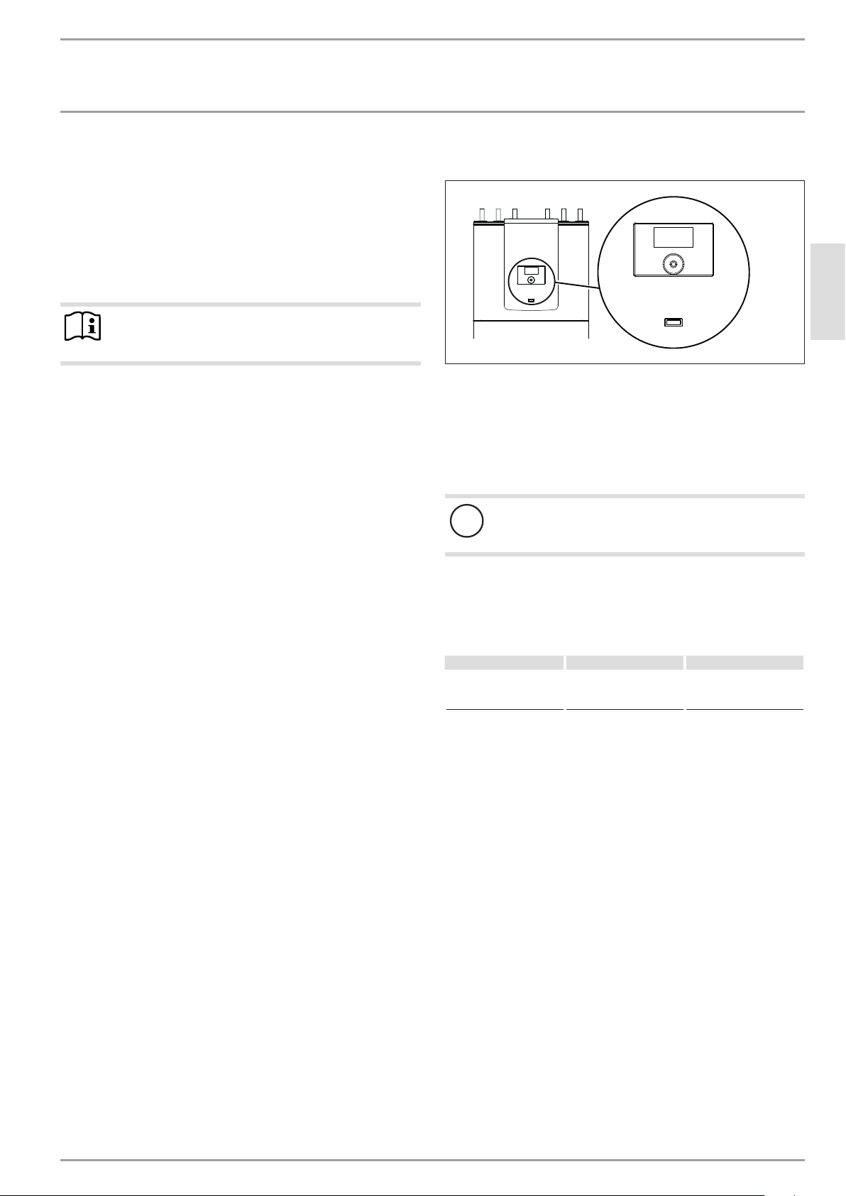
Control unit
The system is controlled by means of the integral heat pump manager.
The heat manager is suitable for the control of a direct heating
circuit and a heating circuit with mixer.
A seven-day heating program is integrated in the heat pump manager which you can use to set the times and temperatures for
central heating and DHW heating.
You can extend the heat pump manager with the following components:
- Room temperature controllers FE7 and FEK for controlling
the direct heating circuit and the heating circuit with mixer.
- Mixer module MSM, if connecting a second heating circuit
with mixer
5. Settings
The system is controlled by means of the integral heat pump manager.
Please observe the heat pump manager operating and instal-
lation instructions.
6. Cleaning, care and maintenance
Material losses
!
Only qualified contractors may perform maintenance
work, such as electrical safety checks.
A damp cloth is sufficient for cleaning all plastic and sheet metal
parts. Never use abrasive or corrosive cleaning agents.
7. Troubleshooting
Fault Cause Remedy
No hot water
Heating system remains
cold
If you cannot remedy the fault, notify your contractor. To facilitate
and speed up your request, provide the number from the type
plate (000000-0000-000000).
Faulty fuses/MCBs
Check the fuses/MCBs in
your fuse box/distribution panel.
ENGLISH
D0000051958
www.stiebel-eltron.com HSBB 3 | 29
Page 6

INSTALLATION
Safety
INSTALLATION
8. Safety
Only a qualified contractor should carry out installation, commissioning, maintenance and repair of the appliance.
- If you are installing the appliance in a boiler room together
with other heating equipment, ensure that the operation of
other heating equipment will not be impaired.
10.3 Transport
Material losses
!
The appliance is unsuitable for lifting by hoist.
8.1 General safety instructions
We guarantee the trouble-free function and operational reliability only if original accessories and spare parts intended for the
appliance are used.
8.2 Instructions, standards and regulations
Note
Observe all applicable national and regional regulations
and instructions.
9. Appliance description
9.1 Standard delivery
The following are delivered with the appliance:
- 1 contact sensor
- 1 outside temperature sensor AFS 2
- 4 appliance feet
- 4 sliding blocks for the appliance feet
9.2 Accessories
- Remote control for heating operation
- High limit safety cut-out STB-FB
- Pressure hoses
- Water softener HZEA
Material losses
!
Store and transport the appliance at temperatures of
+5°C to +50°C.
To protect the appliance from damage, transport it in its
packaging.
Use the angle brackets at the back of the appliance as a
transport aid.
Where space for transport is restricted, you may also move the
appliance tipped backwards at an angle.
Material losses
!
Fittings may come loose during transport.
After transport, check all fittings on the cylinder and
on the hydraulic assembly for tightness.
Retighten the fittings if required.
10.4 Minimum clearances
≥500 ≥100
10. Preparations
10.1 General information
To reduce line losses, keep the distance short between the appliance and the heat pump.
10.2 Installation site
Material losses
!
Never install the appliance in wet rooms.
Installation site requirements:
- free from the risk of frost
- The room must not be subject to a risk of explosions arising
from dust, gases or vapours.
- Load-bearing floor (for the weight of the appliance, see
chapter "Specification / Data table")
30 | HSBB 3 www.stiebel-eltron.com
Maintain the minimum clearances in order to ensure trou-
ble-free operation of the appliance and to allow enough
space for maintenance work.
≥100
≥800
D0000049926
Page 7
INSTALLATION
Installation
11. Installation
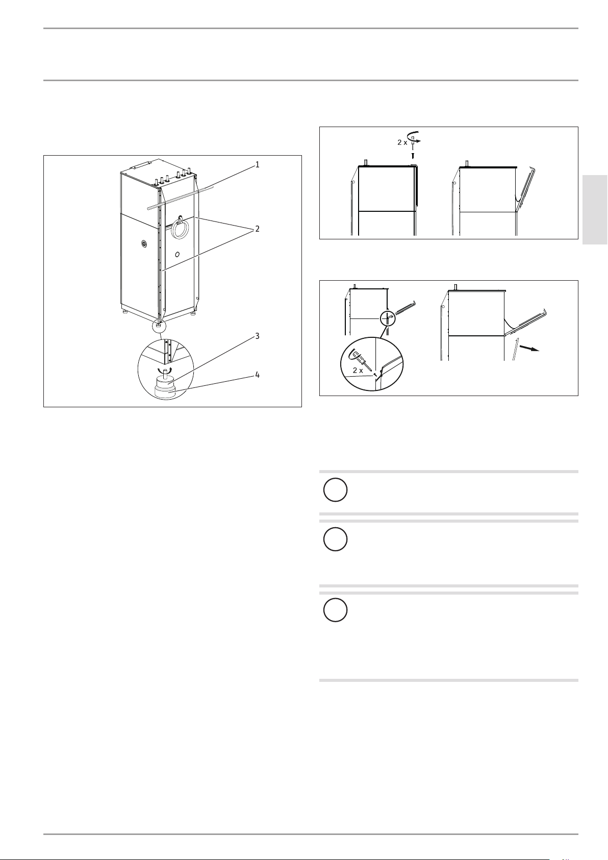
11.1 Siting
1
2
3
4
1 Transport tube (on the installation side)
2 Transport aids
3 Appliance foot
4 Sliding block
Undo the four screws from the non-returnable pallet.
Remove the washers.
Remove the appliance feet from the pack.
Tilt the appliance and wind in the appliance feet.
Lift the appliance off the pallet.
You may need to use the sliding blocks provided to help you
position the appliance.
Observe minimum clearances (see chapter "Preparations /
Minimum clearances").
Remove the transport aids.
Level the appliance horizontally using its adjustable feet.
11.2 Opening the appliance
Undo the fixing screws on the top appliance door.
Open the top appliance door.
D0000050019
Undo and remove the fixing screws from the lower appliance
door.
Remove the lower appliance door.
11.3 Hydraulic connection
Material losses
!
Carry out all water connection and installation work in
accordance with regulations.
Material losses
!
The heating system to which the appliance is connected
must be installed by a qualified contractor in accordance
with the water installation drawings that are part of the
technical guides.
Material losses
!
When fitting additional shut-off devices, install a further
safety valve in an accessible location on the heat generator itself or in the flow line in close proximity to the
heat generator.
There must be no shut-off device between the heat generator and the safety valve.
ENGLISH
D0000050136
D0000050137
Install the DHW outlet line and the cold water supply line
(see chapter "Specification/ Dimensions and connections").
Please note that, depending on the supply pressure, you may
also need a pressure reducing valve.
Debris (e.g. welding pearls, rust, sand, sealant, etc.) can im-
pair the operational reliability of the heat pump.
Thoroughly flush the pipework before connecting the heat
pump.
Ensure the heating flow and return are connected correctly
(see chapter "Specification/ Dimensions and connections").
www.stiebel-eltron.com HSBB 3 | 31
Page 8
INSTALLATION
Installation
Provide thermal insulation in accordance with applicable
regulations.
Oxygen diffusion
Material losses
!
Avoid open heating systems and plastic pipes in underfloor heating systems which are permeable to oxygen.
In underfloor heating systems with plastic pipes that are permeable to oxygen and in open vented heating systems, oxygen
diffusion may lead to corrosion on the steel components of the
heating system (e.g. on the indirect coil of the DHW cylinder, on
buffer cylinders, steel heating elements or steel pipes).
Material losses
!
The products of corrosion (e.g. rusty sludge) can settle in
the heating system components and can result in a lower
output or fault shutdowns due to reduced cross-sections.
Supply lines
The maximum permissible line length between the appliance and
the heat pump will vary, depending on the version of the heating
system (pressure drop).
As a standard value, assume a maximum line length of 10m
and a pipe diameter of 22-28mm.
Protect the flow and return lines against frost with sufficient
thermal insulation.
Provide thermal insulation in accordance with applicable
regulations.
Only use weather-resistant cables.
Also protect all supply lines/cables against humidity, damage
and UV radiation by means of a conduit.
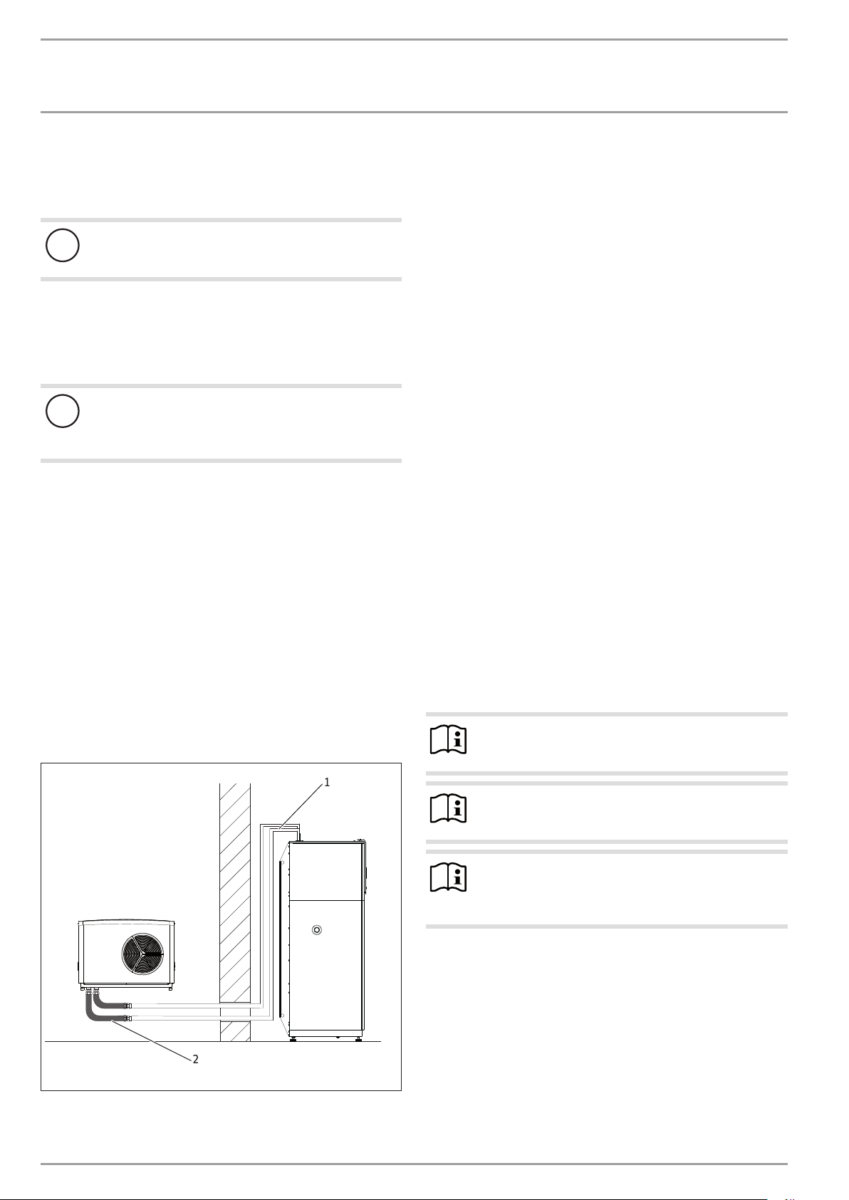
Sample installation
1
11.4 Connection to the heat pump
The appliance and the heat pump are connected to one another hydraulically via pipes carrying heating water. To reduce the
transmission of structure-borne noise on the water side, connect
the appliance to the heat pump with pressure hoses (not required
for WPL 15-25 A).
When sizing the pipes, take the following information into
account:
Available pressure differential
If you exceed the permissible value, the pressure drop in the heating system could result in a reduced heating output.
When sizing the pipes, ensure that the available external
pressure differential is not exceeded (see chapter "Specification/ Data table").
When calculating the pressure drop, take account of the flow
and return lines and the pressure drop of the heat pump.
The pressure drop must be covered by the available pressure
differential.
11.5 Filling the system
Water quality
Carry out a fill water analysis before the system is filled. This
analysis may, for example, be requested from the relevant water
supply utility.
To avoid damage as a result of scaling, it may be necessary to
soften or desalinate the fill water. Always observe the fill water
limits specified in chapter "Specification / Data table".
Recheck these limits 8-12weeks after commissioning and
during the annual system service.
Note
To prevent corrosion, desalinate water with conductivity
>1000μS/cm before use.
Note
If you treat the fill water with inhibitors or additives, the
same limits as for desalination apply.
Note
Suitable appliances for water softening, as well as for
filling and flushing heating systems, can be obtained from
trade suppliers.
2
D0000050024
1 Pipes carrying heating water
2 Pressure hoses
32 | HSBB 3 www.stiebel-eltron.com
Page 9

INSTALLATION
Installation
11.5.1 Filling the heating system
Material losses
!
Never switch on the power before filling the system.
In the delivered condition, the diverter valve of the MFG is positioned at the centre, enabling the heating and DHW circuits to
be filled evenly. When power is switched on, the diverter valve
automatically moves into the central heating position.
To fill or drain the system later, you must first place the diverter
valve into its centre position.
For this, enable controller parameterDRAIN HYDin the DIAGNOSIS°/ RELAY TEST SYSTEM menu.
1
11.6 Venting the appliance
Multi-function assembly (MFG)
To vent, temporarily open the quick-action air vent valve in
the multi-function assembly (MFG).
1 Quick-action air vent valve
2 PCB
Material losses
!
The air vent in the knurled cap of the quick-action air vent
valve must not point towards the MFG PCB.
Turn the air vent in the direction shown in the fol-
lowing diagram.
1
ENGLISH
2
D0000051959
3
1 Diaphragm expansion vessel (heating system)
2 Cap shut-off valve
3 Drain valve (heating system)
Fill the heating system via the drain valve.
After filling the heating system, check the cap shut-off valve
at the diaphragm expansion vessel for tightness.
Vent the pipework.
11.5.2 Filling the DHW cylinder
1 Drain valve (DHW cylinder)
Fill the DHW cylinder via the drain valve.
Open all downstream draw-off valves/taps until the appli-
ance is full and the pipework is free of air.
Carry out a tightness check.
Check the safety valve.
2
1
D0000050021
D0000051960
Material losses
!
Close the quick-action air vent valve again after venting.
D0000050022
www.stiebel-eltron.com HSBB 3 | 33
Page 10

INSTALLATION
Installation
Safety valve on the heating water side
1
2
3
1 Drain hose
2 Fixing
3 Drain
Size the drain pipe so that water can drain off unimpeded
when the safety valve is fully opened.
Ensure that the drain hose of the safety valve is open to the
outside.
Install the drain hose of the safety valve with a constant fall
to the drain. When installing the drain, never kink the drain
hose.
Secure the drain hose by suitable means, to prevent any hose
movement in the event of water being discharged.
11.7 DHW connection
To connect the DHW, remove the lower front panel (see chapter
"Maintenance / Removing the lower front panel").
Material losses
!
Carry out all water connection and installation work in
accordance with regulations.
Material losses
!
The DHW outlet connection is pre-fitted with a plastic
union nut and a soft rubber gasket.
The torque of the plastic union nut depends on the gasket
used.
15Nm = pre-fitted soft rubber gasket.
25Nm = alternative hard gasket.
Keep to the permissible torque.
Material losses
!
D0000051962
11.7.1 Permissible materials
Cold water line
Galvanised steel, stainless steel, copper and plastic are approved
materials.
DHW line
Stainless steel, copper and plastic pipework are approved.
Operate the appliance only with pressure-tested taps.
Material losses
!
The maximum permissible pressure must not be exceeded (see chapter "Specification/ Data table").
Safety valve on the domestic hot water side
Install a type-tested safety valve in the cold water supply
line. Please note that, depending on the supply pressure, you
may also need a pressure reducing valve.
The safety valve discharge aperture must remain open to
atmosphere.
Install the safety valve drain pipe with a constant fall to the
drain.
Size the drain so that water can drain off unimpeded when
the safety valve is fully opened.
Flush the pipes thoroughly.
1
1 Drain (DHW cylinder)
Fill the DHW cylinder via the drain.
Open all downstream draw-off valves/taps until the appli-
ance is full and the pipework is free of air.
Carry out a tightness check.
D0000050022
34 | HSBB 3 www.stiebel-eltron.com
Page 11

INSTALLATION
Power supply
12. Power supply
WARNING Electrocution
Carry out all electrical connection and installation work
in accordance with national and regional regulations.
WARNING Electrocution
Before working on the appliance, isolate it from the
power supply at the control panel.
1
WARNING Electrocution
Only use a permanent connection to the power supply.
Ensure the appliance can be separated from the power
supply by an isolator that disconnects all poles with at
least 3 mm contact separation. This requirement can be
met with contactors, circuit breakers, fuses/MCBs, etc.
Material losses
!
Provide separate fuses for the two power circuits of the
appliance and the control unit.
Material losses
!
The specified voltage must match the mains voltage. Observe the type plate.
Note
Electrical connection work must only be carried out by
a qualified contractor and in accordance with these instructions.
Note
Permission to connect the appliance may need to be obtained from your local power supply utility.
Observe VDE 0100 [or local regulations] and the reg-
ulations of your local power supply utility.
ENGLISH
D0000050019
1 Cable entry
The wiring chamber of the appliance is located behind the lower
appliance door. If the lower appliance door is closed, see chapter
"Opening the appliance".
Route all connecting cables and sensor leads through the
cable entry into the appliance.
Route all connecting cables and sensor leads through the
gap in the centre of the appliance so they reach as far as the
connection PCB.
Connect the supply cables and sensor leads as detailed
below.
Install cables with the following cross-sections in accordance with
the respective fuse rating:
Note
If there is an emergency/booster heater(DHC) integrated
into the heat pump, connect it directly in the heat pump.
MCB/fuse
rating
B 16 A
B 16 A
B 16 A Control cable 1.5 mm²
Electrical data is provided in chapter "Specification / Data table".
!
Assignment Cable cross-section
Electric emergency/
booster heater
(DHC)
3-phase
Electric emergency/
booster heater
(DHC)
Single phase
Material losses
Provide separate fuses/MCBs for the two power circuits,
i.e. for the compressor and the electricemergency/booster heater circuits.
2.5 mm² for routing through a wall.
1.5 mm² with only two live cores and
routing on a wall or in an electrical conduit on a wall.
2.5 mm² for routing through a wall.
1.5 mm² when routing multi-core cables
on a wall or in an electrical conduit on
a wall.
www.stiebel-eltron.com HSBB 3 | 35
Page 12

INSTALLATION
STEUERSPANNUNG
Power supply
12.7.1 Electric emergency/booster heater
General
Appliance
function
Mono energetic operation
Emergency
mode
Effect of the electric emergency/booster heater
If the heat pump undershoots the dual mode point, the electric emergency/booster heater safeguards both the heating
operation and the delivery of high DHW temperatures.
Should the heat pump suffer a fault that prevents its continued operation, the heating output will be covered by the electric emergency/booster heater.
Power connection 3-phase HSBB 3
X3 Electric emergency/booster heater (DHC)
L1, L2, L3, N, PE
Connected load Terminal assignment
2.9 kW L1 PE
5.9 kW L1 L2 PE
8.8 kW L1 L2 L3 PE
Power connection single phase only HSBB 3S
Control voltage
X4 Control voltage (control outputs)
DHW DHW charging pump and N (X25), PE
Zirk. DHW circulation pump N (X25), PE
2.WEWW 2nd DHW heat generator and N (X25), PE
M(Z) Mixer close
M(A) Mixer open
MKP Mixer circuit pump and N (X25), PE
HKP Heating circuit pump and N (X25), PE
KUE/Solar Solar circuit pump / cooling output
secondHS Heat source 2 and N (X25), PE
secondHS Heat source 2 and N (X25), PE
D0000051961
EVU Enable signal
L (mains)
X24 PE
X25 N
Material losses
!
Only connect energy efficient circulation pumps ap-
proved by us to the pump connections.
If you are using energy efficient circulation pumps that
have not been approved by us, use a relay with a breaking capacity of at least 10A/250VAC or our WPM-RBS
relay set.
D0000051963
D0000052085
X3 Electric emergency/booster heater (DHC)
L, L, N, N, PE
Connected load Terminal assignment
3.0 kW L N PE
3.2 kW L N PE
6.2 kW L L N PE
36 | HSBB 3 www.stiebel-eltron.com
Page 13

INSTALLATION
KLEINSPANNUNG
Power supply
Low voltage, BUS cable and service
X2 Low voltage
Rem.Contr. 3 Remote control
Rem.Contr. 1 Remote control
T(MK) Mixer circuit temperature sensor and earth (X26)
T(AUSSEN) Outside temperature sensor and earth (X26)
T(DHW) DHW cylinder sensor
T(KOLL) Collector sensor
T(KUE)/T(WW) For solar connection DHW sensor bottom
T(2. WE) Temperature sensor heat generator 2
T(Puffer) Buffer cylinder sensor
X1 Service (CAN BUS)
H High
L
⊥
+
X26 GND
For cooling flow sensor
Low
Ground
(only in conjunction with FEK)
12.1 Sensor installation
12.1.1 Contact sensor AVF 6 (included in the pack supplied)
Connect an additional return sensor in combination with the
following heat pump types:
- WPL 13 E/cool
- WPL 10 I
- WPL 10 AC(S)
- WPL 15-25 AC(S) (only in combination with a buffer cylinder)
- WPL 08-22 (S) Trend (only in combination with a buffer
cylinder)
D0000051965
For systems without a buffer cylinder
Fit the sensor in the heating circuit return as a contact sensor
and if necessary, downstream of any overflow valve installed.
For systems with a buffer cylinder
Fit the sensor as a return temperature sensor in the buffer
cylinder.
Installation:
The electrical connection is made at the user interface, specifically
at the “T/Buffer” terminal.
ENGLISH
BUS connection
Material losses
!
Route BUS cables, power cables and sensor leads separately.
Install a J-Y (St) 2 x 2 x 0.8mm² cable as BUS to the heat
pump.
A1
X2
11 1213 14
H L - +
4321
A1 WPM 3 heat pump manager
A2 Operating unit
A3 Heat pump
A3
A2
Clean the pipe.
Apply heat conducting paste.
Secure the sensor with a cable tie.
12.1.2 Outside temperature sensor AFS 2 (included in the pack
supplied)
The temperature sensors have a significant influence on the function of your heating system. Therefore ensure sensors are correctly
positioned and well insulated.
26�04�01�0066
Install the outside temperature sensor on a north or
north-eastern wall. Minimum clearances: 2.5 m above the
ground, and 1 m to the side of windows and doors. The
outside temperature sensor should be freely exposed to the
elements but not placed in direct sunlight.
Never mount the outside temperature sensor above win-
dows, doors or air ducts.
26�03�01�1431
26�03�21�0052
www.stiebel-eltron.com HSBB 3 | 37
Page 14

INSTALLATION
Power supply
Connect the outside temperature sensor to terminal
X2(T(AUSSEN)) and to the earth block for low voltage X26 of
the appliance.
Installation:
Remove the cover.
Secure the base with the screw supplied.
Connect the cable.
Replace the cover. The cover must audibly click into place.
12.1.3 Sensor resistance values
Temperature in °C PT 1000 sensor
Resistance in Ω
- 30 843 1250
- 20 922 1367
-10 961 1495
0 1000 1630
10 1039 1772
20 1078 1922
25 1097 2000
30 1117 2080
40 1155 2245
50 1194 2417
60 1232 2597
70 1271 2785
80 1309 2980
90 1347 3182
100 1385 3392
110 1423 --120 1461 ---
KTY sensor
Resistance in Ω
12.3 FEK remote control
FEK terminal strip
2 3 4
L
5
+
1
H
6
The FEK remote control enables you to change the set room temperature for heating circuit 1 or heating circuit 2 by ± 5 °C as well
as the operating mode. Connect the remote control to terminals
H, L and + to terminal strip X2 of the appliance.
Also observe the FEK operating instructions.
12.4 Internet Service Gateway ISG
The Internet Service Gateway ISG enables you to operate the heat
pump in your local home network and via the internet when on
the go. Connect the Internet Service Gateway to terminals H, L,
and to terminal strip X2 of the appliance.
The ISG power supply is not provided via the heat pump.
Also observe the ISG operating instructions.
26�03�01�0094
12.2 FE7 remote control
Connection array FE7
1 2 3
3
The FE7 remote control enables you to adjust the set room temperature for heating circuit 1 or heating circuit 2 by ± 5 °C in automatic
mode only. You can also change the operating mode. Connect the
remote control to terminals Rem.con.1 and Rem.con.3 at terminal
strip X2 and to the LV earth terminal strip X26 of the appliance.
1
26�21�01�0008
38 | HSBB 3 www.stiebel-eltron.com
Page 15

INSTALLATION
Commissioning
13. Commissioning
A qualified contractor must commission the appliance, make all
the settings at the commissioning level of the heat pump manager,
and instruct the user.
Carry out commissioning in accordance with these instructions,
the operating and installation instructions for the heat pump manager and the connected heat pump.
Our customer support can assist with commissioning, which is a
chargeable service.
If the appliance is intended for commercial use, observe the rules
of the relevant Health & Safety at Work Act during commissioning.
For further details, check with your local authorising body (in
Germany, for example, this is the TÜV).
13.1 Checks before commissioning the heat pump
manager
Material losses
!
Observe the maximum system temperature in underfloor
heating systems.
Check that the heating system is filled to the correct pressure
and the quick-action air vent valve is closed.
Check whether the outside temperature sensor is correctly
positioned and connected.
Check whether the power supply is connected correctly.
Check whether the signal cable to the heat pump (BUS) is
correctly connected.
13.1.1 High limit safety cut-out
At ambient temperatures below -15 °C the high limit safety cut-out
in the multi-function assembly may respond.
Check whether the high limit safety cut-out has tripped.
13.2 Commissioning the heat pump manager
Commission the heat pump manager and make all settings in
accordance with the operating and installation instructions of the
heat pump manager.
Note
For DHW mode, ensure that parameterDHW PAR OPRTN
is set in the heat pump manager. To ensure that the
charging pump is enabled even in DHW mode, set this
parameter accordingly.
Note
For calculating the amount of heat, in the case of single
phase connection, set the parameterNUMBER OF STAGESin the heat pump manager in the menu SETTINGS/ HEATING/ELECTRIC REHEATING to2.
13.3 Appliance handover
Explain the appliance function to users and familiarise them
with its operation.
Make users aware of potential dangers.
Hand over these operating and installation instructions to
users for safe-keeping.
14. Shutdown
Material losses
!
Observe the temperature application limits and the minimum circulation volume on the heat consumer side (see
chapter "Specification / Data table").
Material losses
!
The system's active frost protection is not guaranteed if
the power supply is interrupted.
Never interrupt the power supply even outside the
heating season.
ENGLISH
Material losses
!
If the heat pump and frost protection are completely
switched off, drain the system on the water side.
Information on draining the DHW cylinder can be found
in chapter "Maintenance".
1
D0000051964
1 High limit safety cut-out reset button
Reset the high limit safety cut-out by pressing the reset
button.
That way the safety functions that protect the system remain enabled, e.g. frost protection.
www.stiebel-eltron.com HSBB 3 | 39
Note
The heat pump manager has an automatic summer/winter changeover so you can leave the system switched on
in summer.
If you take the system out of use, set the heat pump manager
to standby.
Page 16

INSTALLATION
Maintenance
15. Maintenance
Before any work on the appliance, disconnect all poles of any
in-built electric components from the power supply.
Regularly vent the safety valve until a full stream of water
flows from it.
The heating system is not free of dirt until the strainers are completely clean following a prolonged pump run.
15.1 DHW cylinder
Opening the appliance
See chapter "Maintenance/ Opening the appliance".
Draining the DHW cylinder
CAUTION Burns
Hot water may escape when draining the DHW cylinder.
Close the shut-off valve in the cold water inlet line.
Open the hot water taps on all draw-off points.
1
15.2 Replacing the signal anode
D0000050023
1 Operating indicator blue (no function)
2 Operating indicator red (status of signal anode)
If the red signal indicator on the user interface illuminates,
replace the signal anode.
1
2
1 Drain valve
Drain the DHW cylinder via the drain valve.
Some residual water will remain in the bottom of the cylinder.
Cleaning and descaling
Material losses
!
Never use descaling pumps or descaling agents to clean
the cylinder.
1
1 Inspection port (fitted signal anode)
Remove the signal anode from the appliance.
Clean the DHW cylinder with a hose that you guide through
the inspection port.
Draw the loosened limescale deposits out through the in-
spection port.
1 Signal anode
D0000050022
2 Pressure switch
The pressure switch is activated as soon as the signal anode is
consumed. The signal indicator illuminates.
Note
The signal anode must be fitted as shown in the diagram.
Check for tightness when fitting the pressure switch.
D0000050022
D0000050022
40 | HSBB 3 www.stiebel-eltron.com
Page 17

INSTALLATION
Specication
16. Specification
16.1 Dimensions and connections
d02
d01
e02
555
470
e01
385
c06
214
c01
130
45
1765
165
750
600
ENGLISH
c12
b01
20-40
HSBB 3
b01 Entry electrical cables
c01 Cold water inlet Diameter mm 22
c06 DHW outlet Diameter mm 22
c12 Safety assembly drain
d01 Heat pump flow Diameter mm 22
d02 Heat pump return Diameter mm 22
e01 Heating flow Diameter mm 22
e02 Heating return Diameter mm 22
www.stiebel-eltron.com HSBB 3 | 41
D0000050025
Page 18

INSTALLATION
A6 (Netzteil)
A1 (WPM3)
X11
X12
X13
X14
X15
X20
X21
X22
B6 B8
X67
X29
2 (N)
1 (L)
X66 X65 X63 X62 X61 X60
5
4
2
1
3
1
2
1
2
1
2
3
2
1
1
2
3
4
1
2
3
4
5
6
7
8
9
10
10
9
8
7
6
5
4
3
2
1
3
3
2
2
1
1
1
4
4
4
4
3
2
1
5 4
3 2 1
5 4
3 2 1
X30 X31 X31 X31
p
OUT
+5V
GND
Hz
T2
T1
+5V
GND
H
L
“+”
“+”
L
H
1 2 3
1 43
“+”
L
H
1 2 3
1 43
“+”
L
H
1 2 3
1 43
L
H
1
2
313
PT 1000
Specication
16.2 Wiring diagrams
HSBB 3
HSBB 3-phasig mit WPM3 und MFG
MFG
A5
F5
T >
X3
X59
K5
K6
K7
DHC (MFG)
L2 L3
L1
1 2 3
2 3
1
1
3
1
3
21
11
12
22
Steuerung
N
X23
4
X25
N
1
3
X1
31
32
X24
E1
N
1 2 3 4 5 6
P2
>
H3
X4
L
EVU
2
1
p
L
N
ws (PWM)
M
br (GND)
1~
Yonos Para 7,5
M2
KUE /
2.WE
2.WE
Solar
3
4 5 6 7 8
K5
4 3 2
“+”
HKP
A5 (MFG)
X72
1
L
H
M(A)
MKP
K6
X71
X70
321 3 2 1
PWM
Zirk. /
K7
2 1
9
X69
WW
10
2.WE WW
X68
6 5
4 3
2
3 4
1
M
M
1~
1~
M3
11
5
2 1
6
M(Z)
GND
A1 WPM 3 heat pump manager
A2 Operating unit
A5 MFG PCB
B1 Flow sensor
B2 Return sensor
A6 Power supply unit
B6 Pressure sensor, heating circuit
B8 Heating circuit flow rate and temperature
B9 (Not assigned) brine circuit flow rate and temperature
E1 Instantaneous water heater (MFG)
F2 High pressure switch
F5 High limit safety cut-out (MFG)
K1 Contactor, starting resistors
K2 Contactor, compressor start
K5 MFG relay
K6 MFG relay
K7 MFG relay
K10 HKP relay
K11 MKP relay
M2 Heating pump motor
M3 MFG heating/DHW diverter valve motor
X1 CAN BUS terminal
X2 Terminals, external low voltage
X3 Terminals, external power
X4 Terminals, external control
X11 Plug, temperature sensor WPM3
X12 Plug, heat source temperature WPM3
X13 Plug, heating circuit with mixer temperature WPM3
X14 Plug, remote control WPM3
X15 Plug, BUS WPM3
42 | HSBB 3 www.stiebel-eltron.com
Page 19

INSTALLATION
Specication
10
A1 (WPM3)
A6 (Netzteil)
1 (L)
2 (N)
Kleinspannung
X2
T(Puffer)
1
X11
2
X30 X31 X31 X31
“+”
“+”
“+”
X12
X13
X14
X15
L
H
L
H
L
H
L
H
3
4
5
6
7
8
9
10
1
2
1
2
1
2
3
H
1
L
2
3
“+”
4
1 2 3
1 43
1 2 3
1 43
1 2 3
1 43
313
2
1
5
4
3
2
X20
1
2
X21
1
9
8
7
6
5
4
3
2
X22
1
X29
T(KUE)/
T(2.WE)
2
1
T(WW)
T(KOLL)
T(WW)
3
4 5 6 7 8 9
T(Aussen)
T(MK)
Fernb.1
Fernb.3
A2
X27
X26
4
GND
1 = H
2 = L
3 =
4 = +12V
3
2
“+”
1 2 3
H
L
X5
4
ENGLISH
1
B4
4
X67
3
X66 X65 X63 X62 X61 X60
1
2
3
4
3
1
2
4
OUT
p
5 4
1
2
4
1
+5V
GND
3 2 1
5 4
PT 1000
T2
3 2 1
T1
GND
OUT
+5V
Hz
2 1
2 1 2 1
B6 B8
X20 Plug, pumps and power-OFF WPM3
X21 Plug, mixer control WPM3
X22 Plug, controller
X23 L terminal, controller
X24 Earth terminal strip, controller
X25 N terminal strip, controller
X26 Earth terminal strip, LV
X27 Terminals, programming unit
X28 Terminals, internal low voltage
X29 Power supply, power supply unit
X30 CAN BUS connection, power supply unit
X31 CAN BUS connection, power supply unit
X59 Terminal strip, MFG load side
X60 Rast 2.5 connector (HP flow temperature)
X61 Rast 2.5 connector (HP return temperature)
X62 Not assigned (HS return temperature)
2 1
85�03�14�0012
X63 Not assigned
X64 Rast 2.5 connector (heating system temperature and flow
rate)
X65 Not assigned (heat source system temperature and flow
rate)
X66 Rast 2.5 connector (heating system pressure)
X67 Not assigned
X68 Rast 2.5 connector (switching the motorised heating/DHW
diverter valve)
X69 Not assigned
X70 Rast 2.5 connector (heating circuit pump, PWM or 1-10V
switching)
X71 Rast 2.5 connector (heat source pump, PWM or 1-10V
switching)
X72 Rast 2.5 connector (CAN BUS)
X80 Connector (CAN BUS)
www.stiebel-eltron.com HSBB 3 | 43
Page 20

INSTALLATION
A6 (Netzteil)
A1 (WPM3)
X20
X21
X22
B6 B8
X67
X29
2 (N)
1 (L)
X66 X65 X63 X62 X61 X60
5
4
2
1
3
2
1
10
9
8
7
6
5
4
3
2
1
3
3
2
2
1
1
1
4
4
4
4
3
2
1
5 4
X30 X31 X31 X31
p
OUT
+5V
GND
Specication
HSBB 3 S
HSBB 1-phasig mit WPM3 und MFG
MFG
A5
F5
T >
X3
X59
K5
K6
K7
DHC (MFG)
L N N
L
1
3
2
1
3
1
3
1
3
21
11
12
22
E1
Steuerung
X23
N
X25
X1
X24
N
1 2 3 4 5 6
P2
>
H3
X4
L
EVU
2
1
p
L
N
ws (PWM)
M
br (GND)
1~
Yonos Para 7,5
M2
KUE /
2.WE
2.WE
3
HKP
Solar
4 5 6 7 8 9 10 11
MKP
M(A)
A5 (MFG)
K5
K6
X72
X71
X70
321 3 2 1
4 3 2
1
“+”
L
H
PWM
Zirk. /
K7
2 1
X69
2.WE WW
WW
X68
6 5
4 3
2
3 4
1
M
M
1~
1~
M3
2 1
5
6
M(Z)
GND
A1 WPM 3 heat pump manager
A2 Operating unit
A5 MFG PCB
B1 Flow sensor
B2 Return sensor
A6 Power supply unit
B6 Pressure sensor, heating circuit
B8 Heating circuit flow rate and temperature
B9 (Not assigned) brine circuit flow rate and temperature
E1 Instantaneous water heater (MFG)
F2 High pressure switch
F5 High limit safety cut-out (MFG)
K1 Contactor, starting resistors
K2 Contactor, compressor start
K5 MFG relay
K6 MFG relay
K7 MFG relay
K10 HKP relay
K11 MKP relay
M2 Heating pump motor
M3 MFG heating/DHW diverter valve motor
X1 CAN BUS terminal
X2 Terminals, external low voltage
X3 Terminals, external power
X4 Terminals, external control
X11 Plug, temperature sensor WPM3
X12 Plug, heat source temperature WPM3
X13 Plug, heating circuit with mixer temperature WPM3
X14 Plug, remote control WPM3
X15 Plug, BUS WPM3
44 | HSBB 3 www.stiebel-eltron.com
Page 21

INSTALLATION
Specication
10
A1 (WPM3)
A6 (Netzteil)
1 (L)
2 (N)
5
4
3
2
1
2
1
9
8
7
6
5
4
3
2
1
X29
X20
X21
X22
X30 X31 X31 X31
Kleinspannung
X2
T(Puffer)
1
X11
2
3
4
5
6
7
8
9
10
1
X12
2
X13
1
2
1
X14
2
3
H
1
X15
L
2
3
“+”
4
“+”
L
H
1 2 3
1 43
“+”
L
H
1 2 3
1 43
“+”
L
H
1 2 3
1 43
313
L
2
H
1
T(KUE)/
T(2.WE)
2
1
T(WW)
T(KOLL)
T(WW)
3
4 5 6 7 8 9
T(Aussen)
T(MK)
Fernb.1
Fernb.3
A2
X27
X26
4
3
GND
2
1 = H
2 = L
3 =
4 = +12V
1
“+”
1 2 3
H
L
X5
4
ENGLISH
B4
4
X67
3
X66 X65 X63 X62 X61 X60
1
2
3
4
3
1
2
4
OUT
p
5 4
1
2
4
1
+5V
GND
3 2 1
5 4
PT 1000
T1
T2
3 2 1
+5V
Hz
2 1
GND
OUT
2 1 2 1
B6 B8
X20 Plug, pumps and power-OFF WPM3
X21 Plug, mixer control WPM3
X22 Plug, controller
X23 L terminal, controller
X24 Earth terminal strip, controller
X25 N terminal strip, controller
X26 Earth terminal strip, LV
X27 Terminals, programming unit
X28 Terminals, internal low voltage
X29 Power supply, power supply unit
X30 CAN BUS connection, power supply unit
X31 CAN BUS connection, power supply unit
X59 Terminal strip, MFG load side
X60 Rast 2.5 connector (HP flow temperature)
X61 Rast 2.5 connector (HP return temperature)
X62 Not assigned (HS return temperature)
2 1
85�03�14�0011
X63 Not assigned
X64 Rast 2.5 connector (heating system temperature and flow
rate)
X65 Not assigned (heat source system temperature and flow
rate)
X66 Rast 2.5 connector (heating system pressure)
X67 Not assigned
X68 Rast 2.5 connector (switching the motorised heating/DHW
diverter valve)
X69 Not assigned
X70 Rast 2.5 connector (heating circuit pump, PWM or 1-10V
switching)
X71 Rast 2.5 connector (heat source pump, PWM or 1-10V
switching)
X72 Rast 2.5 connector (CAN BUS)
X80 Connector (CAN BUS)
www.stiebel-eltron.com HSBB 3 | 45
Page 22

INSTALLATION
Specication
16.3 Details on energy consumption
Product data complies with EU regulations relating to the Directive on the eco-design of energy related products (ErP).
HSBB 3 HSBB 3 S
234264 234265
Manufacturer STIEBEL ELTRON STIEBEL ELTRON
Energy efficiency class C C
Cylinder capacity l 168 168
Standby losses W 79 79
16.4 Data table
HSBB 3 HSBB 3 S
234264 234265
Power consumption
Max. power consumption, circulation pump on the heat-
ing side
Power consumption, emergency/booster heater kW 8.8 5.9
Application limits
Water hardness °dH ≤3 ≤3
pH value (with aluminium compounds) 8.0-8.5 8.0-8.5
pH value (without aluminium compounds) 8.0-10.0 8.0-10.0
Conductivity (softening) μS/cm <1000 <1000
Conductivity (desalination) μS/cm 20-10 0 20-100
Chloride mg/l <30 <30
Oxygen 8-12 weeks after filling (softening) mg/l <0.02 <0.02
Oxygen 8-12 weeks after filling (desalination) mg/l <0.1 <0.1
Hydraulic data
Surface area, indirect coil m² 3.3 3.3
External available pressure differential at 1.0m³/h hPa 700 700
External available pressure differential at 1.5 m³/h hPa 567 567
External available pressure differential at 2 m³/h hPa 374 374
External available pressure differential at 2.5 m³/h hPa 101 101
Cylinder capacity l 168 168
Nominal capacity l 168 168
Energy data
Energy efficiency class C C
Standby energy consumption/24h at 65°C kWh 1.9 1.9
Electrical data
Rated voltage, controller V 230 230
Rated voltage, emergency/booster heater V 400 230
Phases, controller 1/N/PE 1/N/PE
Phases, emergency/booster heater 3/N/PE 2/N/PE
MCB/fuse protection, controller A 1 x B 16 1 x B 16
MCB/fuse protection, emergency/booster heater A 3 x B 16 2 x B 16
Versions
Suitable for Heat pump Heat pump
Suitable for WPL 10 AC(S), WPL 13 E, WPL 15/20/25 AC(S),
IP rating IP20 IP20
Dimensions
Height mm 1780 1780
Width mm 600 600
Depth mm 650 650
Height when tilted mm 1810 1810
Heat transfer area m² 2.4 2.4
Weights
Weight, full kg 332 332
Connections
Connection on the heating side 22 mm 22 mm
Cold water connection 22 mm 22 mm
DHW connection 22 mm 22 mm
W 72 72
WPL 08-22 Trend
Air | water heat pumps 10 AC(S), 13 E, 15/20/25
AC(S), 08-22(S) Trend
46 | HSBB 3 www.stiebel-eltron.com
Page 23

INSTALLATION | GUARANTEE | ENVIRONMENT AND RECYCLING
HSBB 3 HSBB 3 S
Values
Nominal heating flow rate at A2/W35, B0/W35 and 7 K m³/h 1.4 1.4
Total available external pressure differential hPa 335 335
Heat loss kW/24h 1.78 1.78
Min heating flow rate m³/h 0.7 0.7
Max. operating pressure MPa 1.0 1.0
Permissible operating pressure, heating circuit MPa 0.3 0.3
Permissible operating pressure, DHW MPa 1.0 1.0
Expansion vessel volume l 18 18
ENGLISH
Guarantee
The guarantee conditions of our German companies do not
apply to appliances acquired outside of Germany. In countries
where our subsidiaries sell our products a guarantee can only
be issued by those subsidiaries. Such guarantee is only granted if the subsidiary has issued its own terms of guarantee. No
other guarantee will be granted.
We shall not provide any guarantee for appliances acquired in
countries where we have no subsidiary to sell our products.
This will not aect warranties issued by any importers.
Environment and recycling
We would ask you to help protect the environment. After use,
dispose of the various materials in accordance with national
regulations.
www.stiebel-eltron.com HSBB 3 | 47
Page 24

g
y
Deutschland
STIEBEL ELTRON GmbH & Co. KG
Dr.-Stiebel-Straße 33 | 37603 Holzminden
Tel. 05531 702-0 | Fax 05531 702-480
info@stiebel-eltron.de
www.stiebel-eltron.de
Australia
STIEBEL ELTRON Australia Pty. Ltd.
6 Prohasky Street | Port Melbourne VIC 3207
Tel. 03 9645-1833 | Fax 03 9645-4366
info@stiebel.com.au
www.stiebel.com.au
Austria
STIEBEL ELTRON Ges.m.b.H.
Gewerbegebiet Neubau-Nord
Margaritenstraße 4 A | 4063 Hörsching
Tel. 07221 74600-0 | Fax 07221 74600-42
info@stiebel-eltron.at
www.stiebel-eltron.at
Belgium
STIEBEL ELTRON bvba/sprl
't Hofveld 6 - D1 | 1702 Groot-Bijgaarden
Tel. 02 42322-22 | Fax 02 42322-12
info@stiebel-eltron.be
www.stiebel-eltron.be
China
STIEBEL ELTRON (Guangzhou) Electric
Appliance Co., Ltd.
Rm 102, F1, Yingbin-Yihao Mansion, No. 1
Yingbin Road
Panyu District | 511431 Guangzhou
Tel. 020 39162209 | Fax 020 39162203
info@stiebeleltron.cn
www.stiebeleltron.cn
Czech Republic
STIEBEL ELTRON spol. s r.o.
K Hájům 946 | 155 00 Praha 5 - Stodůlky
Tel. 251116-111 | Fax 235512-122
info@stiebel-eltron.cz
www.stiebel-eltron.cz
Finland
STIEBEL ELTRON OY
Kapinakuja 1 | 04600 Mäntsälä
Tel. 020 720-9988
info@stiebel-eltron.fi
www.stiebel-eltron.fi
Verkauf Tel. 05531 702-110 | Fax 05531 702-95108 | info-center@stiebel-eltron.de
Kundendienst Tel. 05531 702-111 | Fax 05531 702-95890 | kundendienst@stiebel-eltron.de
Ersatzteilverkauf Tel. 05531 702-120 | Fax 05531 702-95335 | ersatzteile@stiebel-eltron.de
France
STIEBEL ELTRON SAS
7-9, rue des Selliers
B.P 85107 | 57073 Metz-Cédex 3
Tel. 0387 7438-88 | Fax 0387 7468-26
info@stiebel-eltron.fr
www.stiebel-eltron.fr
Hungary
STIEBEL ELTRON Kft.
Gyár u. 2 | 2040 Budaörs
Tel. 01 250-6055 | Fax 01 368-8097
info@stiebel-eltron.hu
www.stiebel-eltron.hu
Japan
NIHON STIEBEL Co. Ltd.
Kowa Kawasaki Nishiguchi Building 8F
66-2 Horikawa-Cho
Saiwai-Ku | 212-0013 Kawasaki
Tel. 044 540-3200 | Fax 044 540-3210
info@nihonstiebel.co.jp
www.nihonstiebel.co.jp
Netherlands
STIEBEL ELTRON Nederland B.V.
Daviottenweg 36 | 5222 BH 's-Hertogenbosch
Tel. 073 623-0000 | Fax 073 623-1141
info@stiebel-eltron.nl
www.stiebel-eltron.nl
Poland
STIEBEL ELTRON Polska Sp. z O.O.
ul. Działkowa 2 | 02-234 Warszawa
Tel. 022 60920-30 | Fax 022 60920-29
biuro@stiebel-eltron.pl
www.stiebel-eltron.pl
Russia
STIEBEL ELTRON LLC RUSSIA
Urzhumskaya street 4,
building 2 | 129343 Moscow
Tel. 0495 7753889 | Fax 0495 7753887
info@stiebel-eltron.ru
www.stiebel-eltron.ru
Slovakia
TATRAMAT - ohrievače vody s.r.o.
Hlavná 1 | 058 01 Poprad
Tel. 052 7127-125 | Fax 052 7127-148
info@stiebel-eltron.sk
www.stiebel-eltron.sk
Switzerland
STIEBEL ELTRON AG
Industrie West
Gass 8 | 5242 Lupfig
Tel. 056 4640-500 | Fax 056 4640-501
info@stiebel-eltron.ch
www.stiebel-eltron.ch
Thailand
STIEBEL ELTRON Asia Ltd.
469 Moo 2 Tambol Klong-Jik
Amphur Bangpa-In | 13160 Ayutthaya
Tel. 035 220088 | Fax 035 221188
info@stiebeleltronasia.com
www.stiebeleltronasia.com
United Kingdom and Ireland
STIEBEL ELTRON UK Ltd.
Unit 12 Stadium Court
Stadium Road | CH62 3RP Bromborough
Tel. 0151 346-2300 | Fax 0151 334-2913
info@stiebel-eltron.co.uk
www.stiebel-eltron.co.uk
United States of America
STIEBEL ELTRON, Inc.
17 West Street | 01088 West Hatfield MA
Tel. 0413 247-3380 | Fax 0413 247-3369
info@stiebel-eltron-usa.com
www.stiebel-eltron-usa.com
4<AMHCMO=bgibcg>
Irrtum und technische Änderungen vorbehalten! | Subject to errors and technical changes! | Sous réserve
d‘erreurs et de modifications techniques! | Onder voorbehoud van ver
Salvo error o modificación técnica! | Excepto erro ou alteração técnica | Zastrzeżone zmian
ewentualne błędy | Omyly a technické změny jsou vyhrazeny! | A muszaki változtatások és tévedések jogát
fenntartjuk! |
technické zmeny sú vyhradené! Stand 9147
Отсутствие ошибок не гарантируется. Возможны технические изменения.
issingen en technische wijzigingen! |
techniczne i
| Chyby a
A 316812-39670-9171
 Loading...