

Page 1
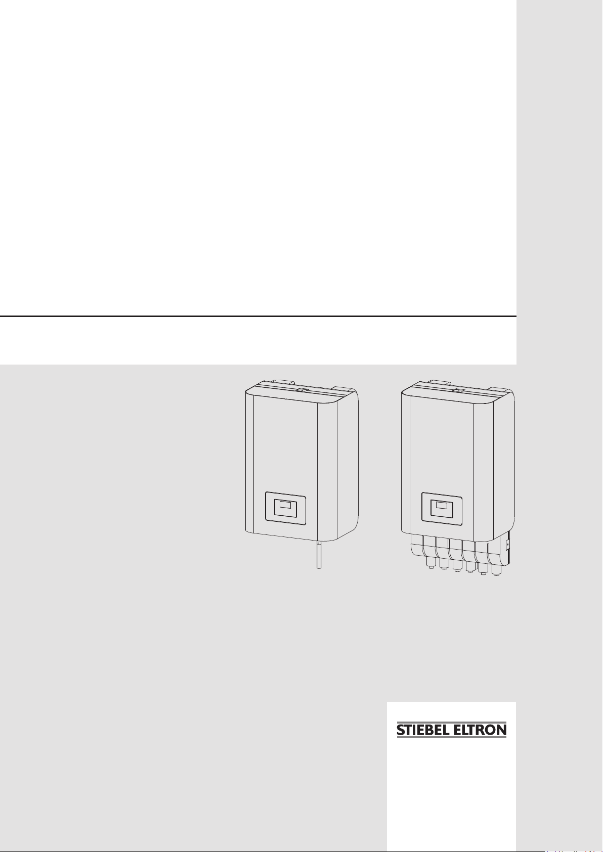
OPERATION AND INSTALLAT ION
Hydraulic module for heat pumps
» HM
» HM Tr end
» HMS
» HMS Trend
Page 2

CONTENTS | SPECIAL INFORMATION
SPECIAL INFORMATION
OPERATION
1. General information �����������������������������������������3
1.1 Relevant documents_____________________________________________ 3
1.2 Safety instructions _______________________________________________ 3
1.3 Other symbols in this documentation _______________________ 3
1.4 Units of measurement __________________________________________ 3
2. Safety ���������������������������������������������������������� 3
2.1 Intended use ______________________________________________________ 3
2.2 General safety instructions ____________________________________ 3
2.3 Test symbols ______________________________________________________ 4
3. Appliance compatibility �������������������������������������4
4. Appliance description ���������������������������������������4
4.1 WPM heat pump manager _____________________________________ 4
5. Maintenance and care ���������������������������������������4
6. Troubleshooting ����������������������������������������������4
INSTALLATION
7. Safety ���������������������������������������������������������� 5
7.1 General safety instructions ____________________________________ 5
7.2 Instructions, standards and regulations ____________________ 5
8. Appliance description ���������������������������������������5
8.1 Standard delivery ________________________________________________ 5
8.2 Accessories ________________________________________________________ 5
9. Installation ���������������������������������������������������� 5
9.1 General information _____________________________________________ 5
9.2 Removing the appliance cap __________________________________ 5
9.3 Minimum clearances ____________________________________________ 6
9.4 Wall mounting ____________________________________________________ 6
9.5 Hydraulic connection ___________________________________________ 7
9.6 Filling the system ________________________________________________ 8
9.7 Venting the appliance ___________________________________________ 8
9.8 Safety valve _______________________________________________________ 9
10. Power supply �������������������������������������������������9
10.1 Electric emergency/booster heater _________________________ 10
10.2 Control voltage __________________________________________________ 10
10.3 WPM heat pump manager ____________________________________ 11
10.4 Sensor installation ______________________________________________ 12
10.5 Connecting external components ___________________________ 13
10.6 Fitting the appliance cap ______________________________________ 13
11. Commissioning ��������������������������������������������� 14
11.1 Check before commissioning the heat pump manager _14
11.2 Appliance handover ____________________________________________ 14
12. Troubleshooting �������������������������������������������� 15
12.1 Resetting the high limit safety cut-out _____________________ 15
13. Maintenance ������������������������������������������������ 15
14. Specification ������������������������������������������������ 16
14.1 Dimensions and connections _________________________________ 16
14.2 Wiring diagram HM | HM Trend ______________________________18
14.3 Wiring diagram HMS | HMS Trend __________________________20
14.4 Data table ________________________________________________________ 22
GUARANTEE
ENVIRONMENT AND RECYCLING
SPECIAL INFORMATION
- The appliance may be used by children aged8
and older and persons with reduced physical,
sensory or mental capabilities or a lack of experience and know-how, provided that they are
supervised or they have been instructed on how
to use the appliance safely and have understood
the resulting risks. Children must never play with
the appliance. Children must never clean the appliance or perform user maintenance unless they
are supervised.
- The connection to the power supply must be in
the form of a permanent connection. Ensure the
appliance can be separated from the power supply by an isolator that disconnects all poles with
at least 3mm contact separation.
- In the event of damage to the power cable this
must always be replaced by a qualified contractor
authorised by the manufacturer, using original
spare parts.
- Fix the appliance in position as described in
chapter "Installation/ Preparations".
- Observe the minimum and maximum water
inlet pressure (see chapter "Specification/ Data
table").
- We recommend regular inspection (to establish
the current condition of the system), and maintenance by a qualified contractor if required (to
return the system to its original condition).
2 | HM (S)| HM(S) Trend www.stiebel-eltron.com
Page 3
OPERATION
General information
OPERATION
1. General information
The chapters "Special Information" and "Operation" are intended
for both the user and qualified contractors.
The chapter "Installation" is intended for qualified contractors.
Note
Read these instructions carefully before using the appliance and retain them for future reference.
Pass on the instructions to any new user where appropriate.
1.1 Relevant documents
WPM operating instructions
WPM commissioning instructions
Operating and installation instructions for the connected
heat pump
Operating and installation instructions for all other com-
ponents in the system
1.3 Other symbols in this documentation
Note
General information is identified by the adjacent symbol.
Read these texts carefully.
Symbol Meaning
!
This symbol indicates that you have to do something. The ac-
tion you need to take is described step by step.
Material losses
(appliance damage, consequential losses and environmental pollution)
Appliance disposal
1.4 Units of measurement
Note
All measurements are given in mm unless stated otherwise.
2. Safety
1.2 Safety instructions
1.2.1 Structure of safety instructions
KEYWORD Type of risk
!
Here, possible consequences are listed that may result
from failure to observe the safety instructions.
Steps to prevent the risk are listed.
1.2.2 Symbols, type of risk
Symbol Type of risk
!
1.2.3 Keywords
KEYWORD Meaning
DANGER Failure to observe this information will result in serious
WARNING Failure to observe this information may result in serious
CAUTION Failure to observe this information may result in non-seri-
Injury
Electrocution
injury or death.
injury or death.
ous or minor injury.
2.1 Intended use
Observe the operating limits listed in chapter "Specification".
This appliance is intended for domestic use. It can be used safely
by untrained persons. The appliance can also be used in a non-domestic environment, e.g. in a small business, as long as it is used
in the same way.
Any other use beyond that described shall be deemed inappropriate. Observation of these instructions and of instructions for any
accessories used is also part of the correct use of this appliance.
2.2 General safety instructions
- The electrical installation and installation of the heating circuit must only be carried out by a recognised, qualified contractor or by our customer support engineers.
- The qualified contractor is responsible for adherence to
all currently applicable regulations during installation and
commissioning.
- Operate the appliance only when fully installed and with all
safety equipment fitted.
- Protect the appliance from dust and dirt ingress during
building work.
WARNING Injury
!
The appliance may be used by children aged 8 and older
and persons with reduced physical, sensory or mental
capabilities or a lack of experience and know-how, provided that they are supervised or they have been instructed on how to use the appliance safely and have
understood the resulting risks. Children must never play
with the appliance. Children must never clean the appliance or perform user maintenance unless they are
supervised.
www.stiebel-eltron.com HM (S)| HM(S) Trend | 3
Page 4

OPERATION
Appliance compatibility
WARNING Injury
!
For safety reasons, only operate the appliance with
the casing closed.
2.3 Test symbols
See type plate on the appliance.
3. Appliance compatibility
The appliance can be operated in conjunction with the following
air | water heat pumps:
- HPA-O 3-8 CS Plus
- HPA-O 7-13 (C)(S) Premium
- WPL 13/18 E, WPL 13/18 cool
- WPL 15-25 A(C)(S)
- WPL 33 HT(S)
- WPL 07-17 ACS classic
- WPL 19-24 I, A
4. Appliance description
The appliance is a hydraulic module for air/water heat pumps
installed outdoors and is installed by wall mounting inside the
thermal envelope of the building. Connection to the water side
of the appliance is from below. Connections are provided on the
appliance for the heat pump flow, the heating system flow and
for the heat exchanger for DHW heating. A further connection is
intended for the drain hose from the safety valve.
The following are integrated into the appliance: a diaphragm expansion vessel with 24litre capacity, a high efficiency [HE heating
circuit pump sized in line with heating output, an electric emergency/booster heater and a WPM heat pump manager.
6. Troubleshooting
If you cannot remedy the fault, notify your qualified contractor.
To facilitate and speed up your enquiry, please provide the serial
number from the type plate. The type plate is located at the front
top, on the right or left hand side of the casing.
Sample type plate
1
Montageanweisung beachten! Dichtheit geprüft!
1 Number on the type plate
*xxxxxxxxxxxxxxxxxx*
Made in Germany
26_03_01_1570
Particular feature of the HM(S) with ASL-HM
The ASL-HM connector block is equipped with additional connections for the heat pump return, the heating system return and the
return from the heat exchanger for DHW heating. In addition, the
connections are equipped with ball shut-off valves to facilitate
installation.
4.1 WPM heat pump manager
The heat pump manager is responsible for the processes that
control and regulate the heat pump.
5. Maintenance and care
Material losses
!
Maintenance work, such as checking the electrical safety,
must only be carried out by a qualified contractor.
A damp cloth is all you need to care for the plastic parts. Never
use abrasive or corrosive cleaning agents.
We recommend regular inspection (to establish the current condition of the system), and maintenance by a qualified contractor
if required (to return the system to its original condition).
4 | HM (S)| HM(S) Trend www.stiebel-eltron.com
Page 5
INSTALLATION
Safety
INSTALLATION
7. Safety
Only a qualified contractor should carry out installation, commissioning, maintenance and repair of the appliance.
7.1 General safety instructions
We guarantee trouble-free function and operational reliability only
if original accessories and spare parts intended for the appliance
are used.
7.2 Instructions, standards and regulations
Note
Observe all applicable national and regional regulations
and instructions.
8. Appliance description
8.1 Standard delivery
The following are delivered with the appliance:
- 4 double ended screws with rawl plugs, washers and nuts
- 3TAF PT immersion/contact sensor
- 1 AFPT outside sensor
- Installation template
9. Installation
9.1 General information
Note
We do not recommend installing the appliance in wet
rooms. Wet rooms include rooms used, for example, for
washing or drying clothes.
To protect the appliance against damage it should be transported
to the installation location in its original packaging.
Install the appliance in a suitable location close to the heat pump.
Ensure that the wall structure can bear the weight of the appliance
before securing the appliance to the wall.
The wall on which the appliance is to be mounted must be even.
Once mounted, the appliance cap must seal the appliance without
gaps.
Use spacer discs to compensate for any unevenness.
Material losses
!
Always fit the appliance cap when interrupting in-
stallation work for any length of time.
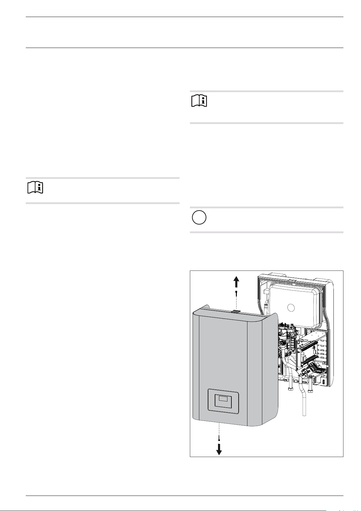
9.2 Removing the appliance cap
HM(S) | HM(S) Trend
8.2 Accessories
- Connector block ASL-HM
D0000041457
www.stiebel-eltron.com HM (S)| HM(S) Trend | 5
Page 6
INSTALLATION
≥150
≥400
≥150
≥400
Installation
ASL-H M
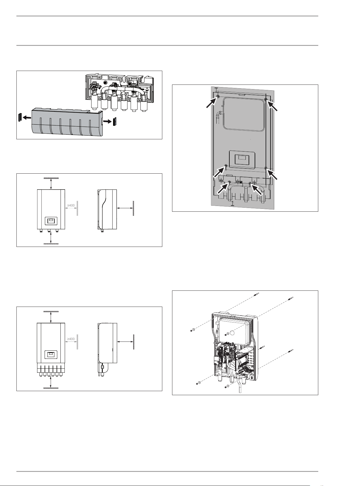
9.3 Minimum clearances
HM (S) | HM(S) Trend without ASL-HM
≥70
≥1000
Maintain the minimum clearances to enable maintenance
work on the appliance.
If the appliance is not installed in a recess, we recommend
leaving 400mm clearance on the right-hand side for the
electrical connection.
9.4 Wall mounting
General
D0000041458
164
Position the installation template horizontally at the required
installation location. The installation template can be found
in the cardboard box.
Mark the holes on the wall. Please note that the bottom two
D0000041600
holes are only required in combination with the ASL-HM.
Drill the holes.
Insert suitable rawl plugs into the holes.
Turn the double ended screws into the rawl plugs.
HM(S) | HM(S) Trend without ASL-HM
D0000042865
HM(S) | HM(S) Trend with ASL-HM
≥70
≥1000
Maintain the minimum clearances to enable maintenance
work on the appliance.
If the appliance is not installed in a recess, we recommend leaving 400mm clearance on the right-hand side for the electrical
connection.
D0000041599
Place the appliance onto the double ended screws, followed
by the washers provided. Secure the appliance with the corresponding nuts.
D0000041461
6 | HM (S)| HM(S) Trend www.stiebel-eltron.com
Page 7
INSTALLATION
Installation
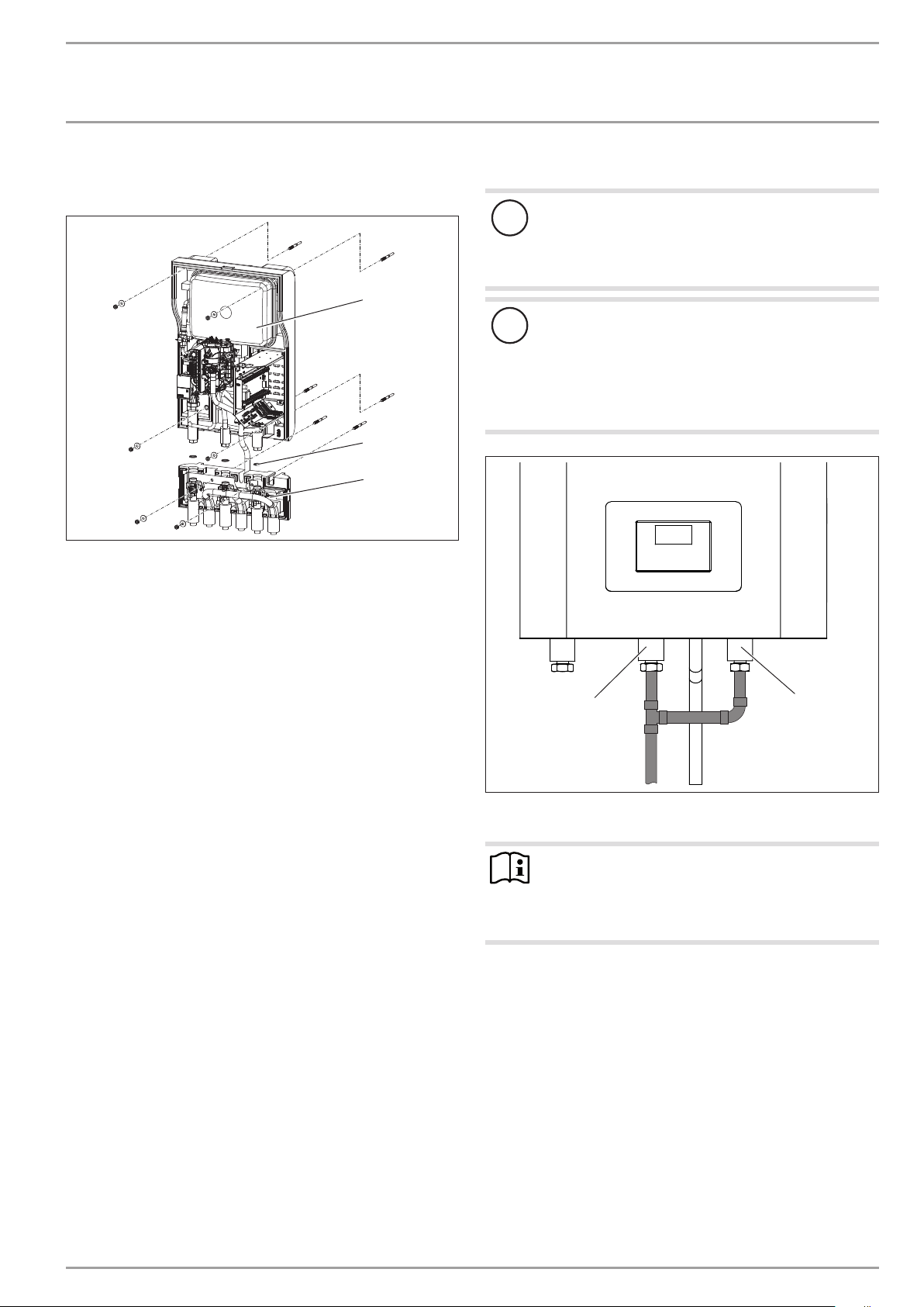
HM(S) | HM(S) Trend with ASL-HM
First mount the ASL-HM connector block on the wall.
1
2
3
1 Appliance
2 Connector block
3 Gaskets
Place the connector block onto the double ended screws, fol-
lowed by the washers provided. Secure the connector block
with the corresponding nuts.
Place the appliance onto the double ended screws, followed
by the washers provided. Secure the appliance with the corresponding nuts.
Connect the appliance to the connector block. Do not forget
the gaskets.
9.5 Hydraulic connection
Material losses
!
The heating system to which the appliance is connected
must be installed by a qualified contractor in accordance
with the water installation drawings that are part of the
technical guides.
Material losses
!
For appliances with connector block or when fitting additional shut-off devices, install a further safety valve in
an accessible location on the heat generator itself or in
the flow line in close proximity to the heat generator.
There must be no shut-off valve between the heat generator and the safety valve.
D0000041460
1
2
1 Heating flow
2 Heat exchanger flow
Note
If the appliance is used without a DHW cylinder, install
a tee.
Link connections “Heating flow” and “Heat exchang-
er flow” with a tee.
Insulate the pipes with insulating material. To prevent air
from entering, ensure that the pipes are sealed up to the apertures in the casing.
D0000059862
www.stiebel-eltron.com HM (S)| HM(S) Trend | 7
Page 8
INSTALLATION
Installation
9.6 Filling the system
9.6.1 General information
Material losses
!
Never switch on the power before filling the system.
Material losses
!
High flow rates or water hammer can damage the appliance.
Fill the appliance at a low flow rate.
In the delivered condition, the diverter valve of the MFG is positioned at the centre, enabling the heating and DHW circuits to be
filled evenly. If power is switched on, the diverter valve automatically moves into the central heating position.
If you intend filling or draining the system later, first place the
diverter valve into its centre position.
For this, enable controller parameter DRAIN HYD in the DIAGNOSIS/ RELAY TEST SYSTEM menu.
9.6.2 Determine the fill pressure
The diaphragm expansion vessel installed in the appliance has a
volume of 24 litres. The pre-charge pressure P0 is 1.5 bar.
If the height difference ∆h between the highest point of the heating system and the diaphragm expansion vessel is no more than
13 m, the diaphragm expansion vessel can be used without any
changes being required.
Fill the heating system at a pressure of at least 1.8 bar (P0
+ 0.3 bar). Observe the safety valve’s response pressure of 3
bar.
If the height difference between the highest point of the heating
system and the diaphragm expansion vessel is more than 13 m,
the pre-charge pressure needs to be adapted.
Calculate the pre-charge pressure:
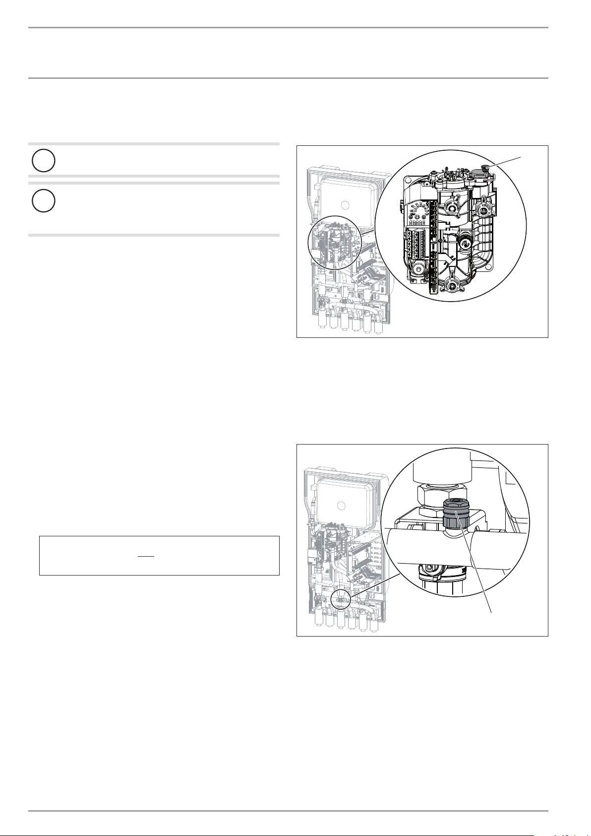
9.7 Venting the appliance
Multifunction assembly (MFG)
1
D0000041463
1 Air vent valve
Vent the pipework by pulling up the red cap on the air vent
valve.
Close the air vent valve after the venting process.
9.7.1 HM(S) | HM(S) Trend with ASL-HM
Heating circuit
∆h
10
+ 0,2 bar
D0000081230
1
1 Air vent valve
Vent the heating circuit at the ASL-HM connector block.
P0 =
Note that the heating system fill pressure increases
accordingly.
Check whether a further external diaphragm expansion ves-
sel needs to be installed.
Fill the heating system at the appropriate pressure (P0 + 0.3
bar). Observe the safety valve’s response pressure of 3 bar.
8 | HM (S)| HM(S) Trend www.stiebel-eltron.com
D0000041462
Page 9

INSTALLATION
Power supply
9.8 Safety valve
1
2
3
1 Drain hose
2 Fixing
3 Drain
Size the discharge outlet so that water can drain off unim-
peded when the safety valve is fully opened.
Ensure that the drain hose of the safety valve is open to the
outside.
Install the drain hose of the safety valve with a constant fall
to the drain. When installing the drain, never kink the drain
hose.
Secure the drain hose by suitable means, to prevent any hose
movement in the event of water being discharged.
10. Power supply
WARNING Electrocution
Carry out all electrical connection and installation work
in accordance with national and regional regulations.
WARNING Electrocution
The connection to the power supply must be in the form
of a permanent connection. Ensure the appliance can
be separated from the power supply by an isolator that
disconnects all poles with at least 3mm contact separation. This requirement can be met with contactors, circuit
breakers, fuses/MCBs, etc.
WARNING Electrocution
Before working on the appliance, isolate it from the
power supply at the control panel.
D0000042471
The connection must only be carried out by a qualified contractor
and in accordance with these instructions.
MCB/fuse
rating
B 16 A
B 16 A
B 16 A Control 1.5 mm²
Electrical data is provided in chapter "Specification / Data table".
Note
The specified voltage must match the mains voltage. Observe the type plate.
Note
Observe the operating and installation instructions of the
heat pump manager and the heat pump.
Use cables with the relevant cross-sections. Observe the ap-
plicable national and regional regulations.
Assignment Cable cross-section
Electric emergency/
booster heater
(DHC)
Three-phase
Electric emergency/
booster heater
(DHC)
1 phase
2.5 mm² for routing through a wall.
1.5 mm² with only two live cores and
routing on a wall or in an electrical conduit on a wall.
2.5 mm² for routing through a wall.
1.5 mm² when routing multi-core cables
on a wall or in an electrical conduit on
a wall.
Material losses
!
Provide separate fuses/MCBs for the two power circuits,
i.e. for the compressor and the electricemergency/booster heater circuits.
Route the electrical cables into the appliance from below, along
the channel provided.
Then route the electrical cables through the strain relief
fittings.
Check the function of the strain relief fittings.
www.stiebel-eltron.com HM (S)| HM(S) Trend | 9
Page 10

INSTALLATION
Power supply
10.1 Electric emergency/booster heater
General
Appliance
function
Mono energetic
operation
Emergency
mode
Electrical connection 3 phase HM | HM Trend
Effect of the electric emergency/booster heater
If the heat pump undershoots the dual mode point, the electric emergency/booster heater safeguards both the heating
operation and the delivery of high DHW temperatures.
Should the heat pump suffer a fault that prevents its continued operation, the heating output will be covered by the electric emergency/booster heater.
Power connection 1 phase only HM (S) | HM (S) Trend
1
2
1
2
XD02 Electr ic emergency/booster heater (DHC)
L1, L2, N1, N2, PE
Connected load Terminal assignment
2.9 kW L1 N1 PE
2.9 kW L2 N2 PE
5.9 kW L1 L2 N1 N2 PE
D0000041480
XD02 Electr ic emergency/booster heater (DHC)
L1, L2, L3, N, PE
Connected load Terminal assignment
2.9 kW L1 N PE
5.9 kW L1 L2 N PE
8.8 kW L1 L2 L3 N PE
10.2 Control voltage
D0000041479
D0000041478
XD 1 .1 Power supply (Netz)
L, 2, N, PE
XD1.2 Power supply ut ilit y (EVU)
L, L'
10 | HM (S)| HM(S) Trend www.stiebel-eltron.com
Page 11

INSTALLATION
Power supply
10.3 WPM heat pump manager
WARNING Electrocution
Only components that operate with safety extra low
voltage (SELV) and that ensure secure separation from
the mains voltage supply may be connected to the low
voltage terminals of the appliance.
Connecting other components can make parts of the appliance and connected components live.
Only use components which have been approved by
us.
X1.1
CAN A
Safety ex tra low voltage
X1.1
CAN A
X1.2
CAN B
X1.3 Signal
X1.4 Signal
X1.5 Signal
X1.6 Signal
X1.7 Signal
X1.8 Signal
X1.9 Signal
X1.10 Signal
X1.11 Signal
X1.12 Signal
X1.13 Signal
X1.14 Constant 12V
X1.15 Constant 12V
X1.16 Signal
X1.17 Signal
X1.3 X1.4 X1.5 X1.6 X1.7 X1.8 X1.9 X1.10 X1.11
CAN B
X2.2 X2.3 X2.4 X2.5 X2.6 X2.7 X2.8 X2.9 X2.10 X2.11 X2.12 X2.13 X2.14 X2.15
X2.1
+
L
H
+
L
H
Earth
Earth
Earth
Earth
Earth
Earth
Earth
Earth
Earth
Earth
Earth
Signal
Input
GND
Input
GND
Earth
Earth
+
CAN (connection for heat pump and WPE heat
-
pump extension)
L
H
+
CAN (connection for FET remote control and
-
ISG Internet Service Gateway)
L
H
1 2Outside temperature sensor
1 2Buffer sensor (heating circuit sensor 1)
1 2Flow sensor
1 2Heating circuit sensor 2
1 2Heating circuit sensor 3
1 2DHW cylinder sensor
1 2Source sensor
1 22nd heat generator (2.WE)
1 2Cooling flow
1 2DHW circulation sensor
1
FE7 remote control/ telephone remote
2
switch/ heating curve optimisation/ SGReady
3
+
Analogue input 0-10V
IN
+
Analogue input 0-10V
IN
1 2PWM output 1
1 2PWM output 2
Safety ex tra low voltage
X1.18
+
CAN B
L
H
X1.19
+
CAN A
L
H
Mains voltage
X2.1
L
L
N
N
PE
X1.17X1.16X1.15X1.14X1.13X1.12X1.2
CAN B
CAN A
D0000071841
X1.19
X1.18
PE
X2.2 L' (power supply
utility input)
L* (pumps L)
X2.3 L
N
PE
X2.4 L
N
PE
X2.5 L
N
PE
X2.6 L
N
PE
X2.7 L
N
PE
X2.8 L
N
PE
X2.9 L
N
PE
X2.10 L
N
PE
X2.11 L
N
PE
X2.12 L
N
PE
X2.13 L
N
PE
X2.14
Mixer OPEN
N
PE
Mixer CLOSE
X2.15
Mixer OPEN
N
PE
Mixer CLOSE
+
CAN (connection for FET remote control and
-
ISG Internet Service Gateway)
L
H
+
CAN (connection for heat pump and WPE heat
-
pump extension)
L
H
L
L
N
N
L'
L* (pumps L)
L
N
PE
L
N
PE
L
N
PE
L
N
PE
L
N
PE
L
N
PE
L
N
PE
L
N
PE
L
N
PE
L
N
PE
L
N
PE
5
N
PE
6
5
N
PE
6
Power supply
L' (power supply utility input)
L* (pumps L)
Heating circuit pump 1
Heating circuit pump 2
Heating circuit pump 3
Buffer charging pump 1
Buffer charging pump 2
DHW charging pump
Source pump/ defrost
Fault output
DHW circulation pump/ 2nd heat
source DHW
2ndheat source heating
Cooling
Mixer, heating circuit 2
( X2.14.1 Mixer OPEN
X2.14.2 Mixer CLOSE )
Mixer, heating circuit 3
( X2.15.1 Mixer OPEN
X2.15.2 Mixer CLOSE )
Note
For every appliance fault, output X2.10 issues a 230V
signal.
In the case of temporary faults, the output switches the
signal through for a specific time.
In the case of faults that result in a permanent appliance
shutdown, the output switches through permanently.
www.stiebel-eltron.com HM (S)| HM(S) Trend | 11
Page 12

INSTALLATION
Power supply
10.4 Sensor installation
10.4.1 Return temperature measuring
Connect an additional return sensor in combination with the
following heat pump types:
- HPA-O 3-8 CS Plus (only in combination with a buffer
cylinder)
- HPA-O 7-13 (C)(S) Premium (only in combination with a buffer cylinder)
- WPL 13 E/cool
- WPL 18 E/cool
- WPL 15-25 A(C)(S) (only in combination with a buffer
cylinder)
- WPL 07-17 ACS classic (only in combination with a buffer
cylinder)
- WPL 19-24 I, A (only in combination with a buffer cylinder)
Note
For heat metering with the WPL 07-17 ACS classic/
HPA-O 3-8 CS Plus in conjunction with the HM(S)
(Trend) hydraulic module, observe the section “Heat
metering with the WPL 07-17 ACS classic / HPA-O 3-8
CS Plu s”.
10.4.2 Heat metering with the WPL 07-17 ACS classic / HPA-O
3-8 CS Plus
Note
Install the following immersion sensor for the heat
pump, in addition to the sensor described in chapter
“Return temperature measuring”.
Use the immersion sensor connected to terminal X61 for heat
metering.
For systems without a buffer cylinder
Fit the sensor in the heating circuit return as a contact sensor
and if necessary, downstream of any overflow valve installed.
For systems with a buffer cylinder
Fit the sensor as a return temperature sensor in the buffer
cylinder.
Installation:
The electrical connection is made at terminal X1.4.
When installing a sensor, observe the commissioning in-
structions for the heat pump manager (see chapter “Connecting external components”).
D0000067540
If required, extend the sensor lead. Use a cable with a mini-
mum diameter of 0.34mm².
D0000067541
12 | HM (S)| HM(S) Trend www.stiebel-eltron.com
Page 13

INSTALLATION
Power supply
If no ASL-HM connector block is used:
1
1 Immersion sensor
Solder the sensor well provided onto the common return
from the DHW and heating system in the building to the heat
pump.
Insert the immersion sensor into the sensor well.
Insulate the pipe in accordance with national and regional
regulations.
If an ASL-HM connector block is used:
Insert the immersion sensor into the sensor well prefitted in
the ASL-HM.
10.6 Fitting the appliance cap
Fit the appliance cap in reverse order to the instructions pro-
vided in chapter “Removing the appliance cap”.
Cable with connector
D0000069971
1 Connection
2 Connector from the programming unit
Fit the connector from the programming unit in the control
panel.
Material losses
!
Take care not to pinch the power cable of the programming unit when fitting the appliance cover.
Arrange the power cable in a loop again and secure
it with the multi-use cable tie provided.
2
1
D0000041465
10.4.3 TAF PT immersion/contact sensor
When installing a sensor, observe the commissioning in-
structions for the heat pump manager (see chapter “Connecting external components”).
10.4.4 Outside temperature sensor AFPT
When installing a sensor, observe the commissioning in-
structions for the heat pump manager (see chapter “Connecting external components”).
10.5 Connecting external components
When installing external components, observe the commis-
sioning instructions for the heat pump manager (see chapter
“Connecting external components”).
www.stiebel-eltron.com HM (S)| HM(S) Trend | 13
Page 14

INSTALLATION
Commissioning
11. Commissioning
Material losses
!
To prevent the temperature falling below the dew point,
the casing must be closed during operation and undamaged.
A contractor must commission the appliance, make all the settings at the commissioning level of the heat pump manager, and
instruct the user.
Commissioning must be carried out in accordance with these operating and installation instructions and the operating and installation instructions of all components belonging to the heat pump
system. Our customer support can assist with commissioning,
which is a chargeable service.
A heat pump system can comprise many different components.
A sound knowledge of the system function is therefore essential.
Where this appliance is intended for commercial use, the rules of
the relevant Health & Safety at Work Act may be applied during
commissioning. For further details, check with your local supervisory body; in Germany for example, this is theTÜV.
11.1 Check before commissioning the heat pump
manager
Check whether the heating system is charged to the correct
pressure.
Have you closed the air vent valve of the multi-function as-
sembly (MFG) again after venting?
Have you placed and connected the outside temperature sen-
sor and the return sensor correctly?
Check whether further sensors are correctly positioned and
connected.
Check whether the power supply is connected correctly.
Check whether the signal cable to the heat pump (bus cable)
is correctly connected.
11.1.1 High limit safety cut-out
At ambient temperatures below -15 °C the high limit safety cut-out
of the multi-function assembly may respond.
Check whether the high limit safety cut-out has tripped.
Material losses
!
When removing the appliance cap, pull the connection
plug of the programming unit out of the control panel.
1 Connection
2 Connector from the programming unit
Material losses
!
Take care not to pinch the power cable of the programming unit when fitting the appliance cap.
Arrange the power cable in a loop and secure it with
the multi-use cable tie provided.
D0000041470
Reset the high limit safety cut-out by pressing the reset
button.
11.2 Appliance handover
Explain the function of the appliance to users and familiarise them
with its operation.
Note
2
1
D0000041465
Hand over these operating and installation instructions
to the user for safe-keeping. Always carefully observe all
information in these instructions. They provide information on safety, operation, installation and maintenance
of the appliance.
Material losses
!
Observe the maximum system temperature in underfloor
heating systems.
14 | HM (S)| HM(S) Trend www.stiebel-eltron.com
Page 15

INSTALLATION
Troubleshooting
12. Troubleshooting
WARNING Electrocution
Isolate the appliance from the power supply when
carrying out any work.
Material losses
!
When removing the appliance cap, pull the connection
plug of the programming unit out of the control panel.
Proceed as follows:
Pull the appliance cap forward by approx. 5cm.
Pull off the connector.
Remove the appliance cover.
12.1 Resetting the high limit safety cut-out
If the heating water temperature exceeds 90°C, the electric emergency/booster heater shuts down.
D0000041470
Remove the cause of the fault.
Reset the high limit safety cut-out by pressing the reset but-
ton. To do so, use a pointed object.
Check whether the heating water is being circulated at a suf-
ficiently high flow rate.
1 Connection
2 Connector from the programming unit
Material losses
!
Take care not to pinch the power cable of the programming unit when fitting the appliance cover.
Arrange the power cable in a loop again and secure
it with the multi-use cable tie provided.
2
1
13. Maintenance
D0000041465
We recommend a regular inspection (to establish the current condition of the system), and maintenance if required (to return the
system to its original condition).
www.stiebel-eltron.com HM (S)| HM(S) Trend | 15
Page 16

INSTALLATION
Specication
14. Specification
14.1 Dimensions and connections
HM(S) | HM(S) Trend without ASL-HM
b01
d29
e01
d01
588
896
c12
81
251
337
422
b01 Entry electrical cables
c12 Safet y valve drain
d01 Heat pump flow Female thread G 1
d29 Heat exchanger flow Female thread G 1
e01 Heating flow Female thread G 1
405
25
95
HM(S) | HM(S) Trend with ASL-HM
b01
d29
e01
d01
d02
590
846
1131
78
163
248
333
418
503
D0000041455
b01 Entry electrical cables
c12 Safet y valve drain
d01 Heat pump flow Diameter mm 28
d02 Heat pump return Diameter mm 28
d29 Heat exchanger flow Diameter mm 28
d30 Heat exchanger return Diameter mm 28
e01 Heating flow Diameter mm 28
e02 Heating return Diameter mm 28
e02
d30
405
c12
25
95
215
D0000041456
16 | HM (S)| HM(S) Trend www.stiebel-eltron.com
Page 17

INSTALLATION
Specication
www.stiebel-eltron.com HM (S)| HM(S) Trend | 17
Page 18

INSTALLATION
Specication
14.2 Wiring diagram HM | HM Trend
AA07 (MFG)
KF22 KF21 KF20
X72
X70
X69
X68
X71
1
4
1112233
232
PWM
6
GND
344
5
1~
M
2
+
1
12 34 56
-
X1.1
MA15
L
H
CAN A
X67
1
2
3
-
L
+
H
X1.2
CAN B
X66
X65
X64
1
1
1
2
2
2
3
3
3
4
445
5
134
421
+SV
OUT
GND
p
1111111111122
2
2
2
X1.5
X1.4
X1.3
BP10
2
X1.6
X1.7
T2
T1
+SV
OUT
GND
Hz
PT 1000
2
2
X1.9
X1.8
X1.10
X63
1
2
BF01
222
X1.11
X1.12
X62
X61
X60
1
1
1
2
2
2
H
1=
L
2=
3=
+12V
4=
1234
X27
AA06
BT02
BT01
XD80
-
3
X1.13
112
+
+
IN
IN
X1.16
X1.15
X1.14
2
X1.17
+
X1.18
L
CAN B
-
L
+
H
H
X1.19
CAN A
L
N
br (GND)
ws (PWM)
M
1~
MA14
AA01 (WPM4)
X2.1
L
L
L
L
L
L
N
N
PE
N
L'
L*
PE
PE
L
N
N
N
PE
PE
PE
X2.10
L
L
L
N
N
N
PE
PE
PE
X2.13
X2.12
X2.11
L
L
L
N
N
N
PE
PE
X2.15
X2.14
N
N
PE
PE
PE
X2.9
X2.8
X2.7
X2.6
X2.5
X2.4
X2.3
X2.2
NETZ EVUDHC (MFG)
BT55
22 32
12
<T
31
21
11
KF22
3
1
3
KF21
AA07
KF20
1
3
1
MFG
X59
L1L2L3N
N L1 L2 L3 NL 2 L L´
EB01
XD02 XD01.1 XD01.2
18 | HM (S)| HM(S) Trend www.stiebel-eltron.com
D0000081112
Page 19

INSTALLATION
Specication
AA01 WPM heat pump manager
AA06 Programming unit
AA07 PCB, booster heater MFG
EB01 Booster heater MFG
BF01 Flow rate and temperature, heating circuit
BP10 Pressure sensor, heating circuit
BT01 Temperature sensor, heat pump flow
BT02 Temperature sensor, heat pump return
BT55 High limit safety cut-out MFG (manual reset)
MA14 Motor, buffer charging pump (PWM/1-10V)
MA15 Motor, diverter valve, heating/DHW
KF20 Relay, booster heater MFG
KF21 Relay, booster heater MFG
KF22 Relay, booster heater MFG
XD01.1 Terminal, power supply
XD01.2 Terminal, power-OFF contact
XD02 Terminal, MFG power supply
XD80 Plug-in connector (CAN bus)
AA01 extra low voltage
AA01-X1.1 Connector, CAN A (WP connection)
AA01-X1.2 Connector, CAN B (FET/ISG connection)
AA01-X1.3 Connector, outside temperature sensor
AA01-X1.4 Connector, buffer temperature sensor BT06
AA01-X1.5 Connector, flow temperature sensor
AA01-X1.6 Connector, heating circuit temperature sensor 2
AA01-X1.7 Connector, heating circuit temperature sensor 3
AA01-X1.8 Connector, DHW cylinder sensor BT20
AA01-X1.9 Connector, source sensor
AA01-X1.10 Connector, heat source 2
AA01-X1.11 Connector, flow, cooling
AA01-X1.12 Connector, DHW circulation sensor
AA01-X1.13 Connector, remote control FE7
AA01-X1.14 Connector, analogue input 0-10V
AA01-X1.15 Connector, analogue input 0-10V
AA01-X1.16 Connector, PWM output 1
AA01-X1.17 Connector, PWM output 2
AA01-X1.18 Connector, CAN B (FET/ISG connection)
AA01-X1.19 Connector, CAN A (MFG)
AA01 Control voltage
AA01-X2.1 Connector, power supply
AA01-X2.2 Connector, power-OFF contact
AA01-X2.3 Connector, heating circuit pump 1
AA01-X2.4 Connector, heating circuit pump 2
AA01-X2.5 Connector, heating circuit pump 3
AA01-X2.6 Connector, buffer charging pump 1
AA01-X2.7 Connector, buffer charging pump 2
AA01-X2.8 Connector, DHW charging pump
AA01-X2.9 Connector, source pump/defrost
AA01-X2.10 Connector, fault output
AA01-X2.11 Connector, DHW circulation pump/ HS2 – DHW
AA01-X2.12 Connector, HS2 – heating
AA01-X2.13 Connector, cooling
AA01-X2.14 Connector, mixer, heating circuit 2 (X2.14.1 Mixer
OPEN/X2.14.2 Mixer CLOSE)
AA01-X2.15 Connector, mixer, heating circuit 3 (X2.15.1 Mixer
OPEN/X2.15.2 Mixer CLOSE)
AA0 6-X27 Terminal, programming unit
AA07-X60 Connector, temperature sensor, heat pump flow
BT01
AA07-X61 Connector, temperature sensor, heat pump re-
turn BT02
AA07-X62 Not assigned – connector, temperature sensor,
heat pump return
AA07-X63 Not assigned – connector, temperature sensor,
DHW cylinder, internal
AA07-X64 Connector, temperature and flow rate, heating
circuit, BF01
AA07-X65 Not assigned
AA07-X66 Rast 2.5 connector (heating system pressure)
BP01
AA07-X67 Not assigned
AA07-X68 Connector, switching, motor, diverter valve cen-
tral heating / DHW
AA07-X69 Not assigned
AA07-X70 Connector, switching, pump, heating circuit PW-
M/1-10V
AA07-X71 Not assigned
AA07-X72 Connector, CAN bus
EB01-X59 Terminal, MFG
www.stiebel-eltron.com HM (S)| HM(S) Trend | 19
Page 20

INSTALLATION
(im MFG 5 nicht verbaut!)
Specication
14.3 Wiring diagram HMS | HMS Trend
AA07 (MFG)
KF22 KF21 KF20
X72
X70
X69
X68
X71
1
4
1112233
232
PWM
6
GND
344
5
1~
M
2
1
12 34 56
3
MA15
X67
1
2
4
421
OUT
X66
X65
X64
X63
X62
X61
X60
1
1
1
1
1
1
1
2
2
2
2
2
2
3
3
3
4
4
5
5
2
H
1=
L
2=
3=
+12V
4=
1234
X27
3 14
T2
T1
+SV
OUT
+SV
GND
p
BP10
PT 1000
GND
Hz
BF01
BT02
BT01
AA06
XD80
L
N
br (GND)
ws (PWM)
M
1~
MA14
-
-
L
L
H
CAN A
2
+
H
X1.3
X1.2
CAN B
+
X1.1
1111111111122
X1.4
2
2
2
2
X1.7
X1.6
X1.5
X1.8
2
2
2
2
X1.9
X1.10
X1.11
X1.12
3
X1.13
+
+
IN
IN
X1.15
X1.14
112
X1.16
2
X1.17
+
-
L
X1.18
H
CAN B
+
-
X1.19
L
CAN A
H
AA01 (WPM4)
X2.9
X2.8
X2.7
X2.6
X2.5
X2.4
X2.3
X2.2
X2.1
L
L
L
L
L
L
L
N
N
N
L'
L*
PE
N
PE
PE
PE
L
N
N
PE
PE
X2.10
L
L
N
PE
L
N
N
PE
PE
X2.11
N
X2.13
X2.12
L
L
N
N
PE
PE
X2.15
X2.14
N
N
PE
PE
PE
NETZ EVUDHC (MFG)
L 2 N L L´
X59
LN N L
MFG
1
L
2
L
1
N
2
N
Zusatz-BHZ
Emergency/booster heater
(not installed in t he MFG 5)
BT55
22 32
12
<T
31
21
11
KF22
3
1
3
KF21
AA07
KF20
1
3
1
EB01
XD02 XD01.1 XD01.2
20 | HM (S)| HM(S) Trend www.stiebel-eltron.com
D0000081112
Page 21

INSTALLATION
Specication
AA01 WPM heat pump manager
AA06 Programming unit
AA07 PCB, booster heater MFG
EB01 Booster heater MFG
BF01 Flow rate and temperature, heating circuit
BP10 Pressure sensor, heating circuit
BT01 Temperature sensor, heat pump flow
BT02 Temperature sensor, heat pump return
BT55 High limit safety cut-out MFG (manual reset)
MA14 Motor, buffer charging pump (PWM/1-10V)
MA15 Motor, diverter valve, heating/DHW
KF20 Relay, booster heater MFG
KF21 Relay, booster heater MFG
KF22 Relay, booster heater MFG
XD01.1 Terminal, power supply
XD01.2 Terminal, power-OFF contact
XD02 Terminal, MFG power supply
XD80 Plug-in connector (CAN bus)
AA01 extra low voltage
AA01-X1.1 Connector, CAN A (WP connection)
AA01-X1.2 Connector, CAN B (FET/ISG connection)
AA01-X1.3 Connector, outside temperature sensor
AA01-X1.4 Connector, buffer temperature sensor BT06
AA01-X1.5 Connector, flow temperature sensor
AA01-X1.6 Connector, heating circuit temperature sensor 2
AA01-X1.7 Connector, heating circuit temperature sensor 3
AA01-X1.8 Connector, DHW cylinder sensor BT20
AA01-X1.9 Connector, source sensor
AA01-X1.10 Connector, heat source 2
AA01-X1.11 Connector, flow, cooling
AA01-X1.12 Connector, DHW circulation sensor
AA01-X1.13 Connector, remote control FE7
AA01-X1.14 Connector, analogue input 0-10V
AA01-X1.15 Connector, analogue input 0-10V
AA01-X1.16 Connector, PWM output 1
AA01-X1.17 Connector, PWM output 2
AA01-X1.18 Connector, CAN B (FET/ISG connection)
AA01-X1.19 Connector, CAN A (MFG)
AA01 Control voltage
AA01-X2.1 Connector, power supply
AA01-X2.2 Connector, power-OFF contact
AA01-X2.3 Connector, heating circuit pump 1
AA01-X2.4 Connector, heating circuit pump 2
AA01-X2.5 Connector, heating circuit pump 3
AA01-X2.6 Connector, buffer charging pump 1
AA01-X2.7 Connector, buffer charging pump 2
AA01-X2.8 Connector, DHW charging pump
AA01-X2.9 Connector, source pump/defrost
AA01-X2.10 Connector, fault output
AA01-X2.11 Connector, DHW circulation pump/ HS2 – DHW
AA01-X2.12 Connector, HS2 – heating
AA01-X2.13 Connector, cooling
AA01-X2.14 Connector, mixer, heating circuit 2 (X2.14.1 Mixer
OPEN/X2.14.2 Mixer CLOSE)
AA01-X2.15 Connector, mixer, heating circuit 3 (X2.15.1 Mixer
OPEN/X2.15.2 Mixer CLOSE)
AA0 6-X27 Terminal, programming unit
AA07-X60 Connector, temperature sensor, heat pump flow
BT01
AA07-X61 Connector, temperature sensor, heat pump re-
turn BT02
AA07-X62 Not assigned – connector, temperature sensor,
heat pump return
AA07-X63 Not assigned – connector, temperature sensor,
DHW cylinder, internal
AA07-X64 Connector, temperature and flow rate, heating
circuit, BF01
AA07-X65 Not assigned
AA07-X66 Rast 2.5 connector (heating system pressure)
BP01
AA07-X67 Not assigned
AA07-X68 Connector, switching, motor, diverter valve cen-
tral heating / DHW
AA07-X69 Not assigned
AA07-X70 Connector, switching, pump, heating circuit PW-
M/1-10V
AA07-X71 Not assigned
AA07-X72 Connector, CAN bus
EB01-X59 Terminal, MFG
www.stiebel-eltron.com HM (S)| HM(S) Trend | 21
Page 22

INSTALLATION
Specication
14.4 Data table
HM HM Tr end HMS HMS Tr end
233010 232805 233827 233826
Power consumption
Power consumption, emergency/booster heater kW 8.8 8.8 5.9 5.9
Application limits
Max. permissible pressure MPa 0.3 0.3 0.3 0.3
Min. application limit on the heating side °C 7 7 7 7
Max. cooling application limit on the heating side °C 70 70 70 70
Hydraulic data
External available pressure differential at 1.5m³/h hPa 661 661 661 661
External available pressure differential at 2.5m³/h hPa 300 300 300 300
External available pressure differential at 2m³/h hPa 468 468 468 468
Electrical data
Frequency Hz 50 50 50 50
Rated voltage, control unit V 230 230 230 230
Rated voltage, emergency/booster heater V 400 400 230 230
Control unit phases 1/N/PE 1/N/PE 1/N/PE 1/N/PE
Emergency/booster heater phases 3/N/PE 3/N/PE 2/N/PE 2/N/PE
Control unit fuse protection A 1 x B 16 1 x B 16 1 x B 16 1 x B 16
Fuse protection, emergency/booster heater A 3 x B 16 3 x B 16 2 x B 16 2 x B 16
Power consumption, circulation pump W 3-76 3-76 3-76 3-76
Versions
Circulation pump type
IP rating IP20 IP20 IP20 IP20
Dimensions
Height mm 896 896 896 896
Height incl. connector block mm 1131 1131 1131 1131
Width mm 590 590 590 590
Depth mm 405 405 405 405
Weights
Weight kg 45 27 45 27
Connections
Connection G 1 G 1 G 1 G 1
Heating water quality requirements
Water hardness °dH ≤3 ≤3 ≤3 ≤3
pH value (with aluminium fittings) 8.0-8.5 8.0-8.5 8.0-8.5 8.0-8.5
pH value (without aluminium fittings) 8.0-10.0 8.0-10.0 8.0-10.0 8.0-10.0
Conductivity (softening) μS/cm <1000 <1000 <1000 <1000
Conductivity (desalination) μS/cm 20-100 20-100 20-100 20-100
Chloride mg/l <30 <30 <30 <30
Oxygen 8-12 weeks after filling (softening) mg/l <0.02 <0.02 <0.02 <0.02
Oxygen 8-12 weeks after filling (desalination) mg/l <0.1 <0.1 <0.1 <0.1
Values
Expansion vessel volume l 24 24 24 24
Yonos PARA 25/7.5, high-
ly efficient circulation
pump
Yonos PARA 25/7.5, high-
ly efficient circulation
pump
Yonos PARA 25/7.5, high-
ly efficient circulation
pump
Yonos PARA 25/7.5, high-
ly efficient circulation
pump
22 | HM (S)| HM(S) Trend www.stiebel-eltron.com
Page 23

GUARANTEE | ENVIRONMENT AND RECYCLING
Guarantee
The guarantee conditions of our German companies do not
apply to appliances acquired outside of Germany. In countries
where our subsidiaries sell our products a guarantee can only
be issued by those subsidiaries. Such guarantee is only granted if the subsidiary has issued its own terms of guarantee. No
other guarantee will be granted.
We shall not provide any guarantee for appliances acquired in
countries where we have no subsidiary to sell our products.
This will not aect warranties issued by any importers.
Environment and recycling
We would ask you to help protect the environment. After use,
dispose of the various materials in accordance with national
regulations.
www.stiebel-eltron.com HM (S)| HM(S) Trend | 23
Page 24

Deutschland
STIEBEL ELTRON GmbH & Co. KG
Dr.-Stiebel-Straße 33 | 37603 Holzminden
Tel. 05531 702-0 | Fax 05531 702-480
info@stiebel-eltron.de
www.stiebel-eltron.de
Verkauf Tel. 05531 702-110 | Fax 05531 702-95108 | info-center@stiebel-eltron.de
Kundendienst Tel. 05531 702-111 | Fax 05531 702-95890 | kundendienst@stiebel-eltron.de
Ersatzteilverkauf Tel. 05531 702-120 | Fax 05531 702-95335 | ersatzteile@stiebel-eltron.de
Australia
STIEBEL ELTRON Australia Pty. Ltd.
6 Prohasky Street | Port Melbourne VIC 3207
Tel. 03 9645-1833 | Fax 03 9645-4366
info@stiebel.com.au
www.stiebel.com.au
Austria
STIEBEL ELTRON Ges.m.b.H.
Gewerbegebiet Neubau-Nord
Margaritenstraße 4 A | 4063 Hörsching
Tel. 07221 74600-0 | Fax 07221 74600-42
info@stiebel-eltron.at
www.stiebel-eltron.at
Belgium
STIEBEL ELTRON bvba/sprl
't Hofveld 6 - D1 | 1702 Groot-Bijgaarden
Tel. 02 42322-22 | Fax 02 42322-12
info@stiebel-eltron.be
www.stiebel-eltron.be
China
STIEBEL ELTRON (Tianjin) Electric Appliance
Co., Ltd.
Plant C3, XEDA International Industry Cit y
Xiqing Economic Development Area
300085 Tianjin
Tel. 022 8396 2077 | Fax 022 8396 2075
info@stiebeleltron.cn
www.stiebeleltron.cn
Czech Republic
STIEBEL ELTRON spol. s r.o.
K Hájům 946 | 155 00 Praha 5 - Stodůlky
Tel. 251116-111 | Fax 235512-122
info@stiebel-eltron.cz
www.stiebel-eltron.cz
Finland
STIEBEL ELTRON OY
Kapinakuja 1 | 04600 Mäntsälä
Tel. 020 720-9988
info@stiebel-eltron.fi
www.stiebel-eltron.fi
France
STIEBEL ELTRON SAS
7-9, rue des Selliers
B.P 85107 | 57073 Metz-Cédex 3
Tel. 0387 7438-88 | Fax 0387 7468-26
info@stiebel-eltron.fr
www.stiebel-eltron.fr
Hungary
STIEBEL ELTRON Kft.
Gyár u. 2 | 2040 Budaörs
Tel. 01 250-6055 | Fax 01 368-8097
info@stiebel-eltron.hu
www.stiebel-eltron.hu
Japan
NIHON STIEBEL Co. Ltd.
Kowa Kawasaki Nishiguchi Building 8F
66-2 Horikawa-Cho
Saiwai-Ku | 212-0013 Kawasaki
Tel. 044 540-3200 | Fax 044 540-3210
info@nihonstiebel.co.jp
www.nihonstiebel.co.jp
Netherlands
STIEBEL ELTRON Nederland B.V.
Daviottenweg 36 | 5222 BH 's-Hertogenbosch
Tel. 073 623-0000 | Fax 073 623-1141
info@stiebel-eltron.nl
www.stiebel-eltron.nl
Poland
STIEBEL ELTRON Polska Sp. z O.O.
ul. Działkowa 2 | 02-234 Warszawa
Tel. 022 60920-30 | Fax 022 60920-29
biuro@stiebel-eltron.pl
www.stiebel-eltron.pl
Russia
STIEBEL ELTRON LLC RUSSIA
Urzhumskaya street 4,
building 2 | 129343 Moscow
Tel. 0495 7753889 | Fax 0495 7753887
info@stiebel-eltron.ru
www.stiebel-eltron.ru
Slovakia
TATRAMAT - ohrievače vody s.r.o.
Hlavná 1 | 058 01 Poprad
Tel. 052 7127-125 | Fax 052 7127-148
info@stiebel-eltron.sk
www.stiebel-eltron.sk
Switzerland
STIEBEL ELTRON AG
Industrie West
Gass 8 | 5242 Lupfig
Tel. 056 4640-500 | Fax 056 4640-501
info@stiebel-eltron.ch
www.stiebel-eltron.ch
Thailand
STIEBEL ELTRON Asia Ltd.
469 Moo 2 Tambol Klong-Jik
Amphur Bangpa-In | 13160 Ayutthaya
Tel. 035 220088 | Fax 035 221188
info@stiebeleltronasia.com
www.stiebeleltronasia.com
United Kingdom and Ireland
STIEBEL ELTRON UK Ltd.
Unit 12 Stadium Court
Stadium Road | CH62 3RP Bromborough
Tel. 0151 346-2300 | Fax 0151 334-2913
info@stiebel-eltron.co.uk
www.stiebel-eltron.co.uk
United States of America
STIEBEL ELTRON, Inc.
17 West Street | 01088 West Hatfield MA
Tel. 0413 247-3380 | Fax 0413 247-3369
info@stiebel-eltron-usa.com
www.stiebel-eltron-usa.com
4<AMHCMO=bgehdj>
Irrtum und technis che Änderunge n vorbehalten! | Subject to errors and technical changes! | S ous réserv e
d‘erreur s e t de m odif icatio ns techniqu es! | Onder voorbehoud van vergissingen en technische wijzigingen! |
Salvo error o modif icación técnica! | Excepto erro ou alteração técnica | Zastrzeżone zmiany technic zne i
ewentualne błędy | O myly a technické změny jsou vyhraze ny! | A muszaki változ tatások és tévedé sek jogát
fenntartjuk ! | Отсу тстви е ошибок не гарантиру ется. Воз можны тех нические и зменени я. | Chyb y a
technické zmeny sú vyhradené! Stand 9375
A 316473-40993-9434
B 314983-40993-9434
 Loading...