

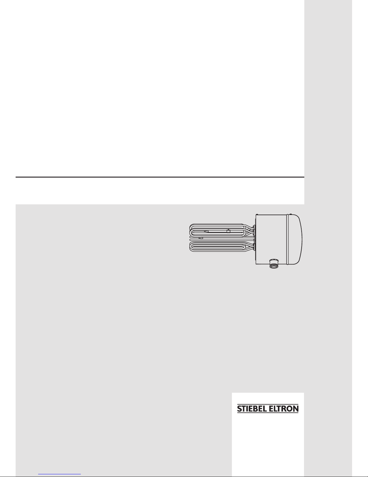
STIEBEL ELTRON FCR 28/180 Si, FCR 28/120 Si, FCR 28/270 Si, FSR 28/90, FCR 28/360 Si Operation & Installation
...Page 1
BEDIENUNG UND INSTALLATION
OPERATION AND INSTALLATION
UTILISATION ET INSTALLATION
BEDIENING EN INSTALLATIE
Heizansch | Flanged immersion heater | Corps de chauffe | Verwarmingsens
» FCR 28/120 Si
» FCR 28/180 Si
» FCR 28/270 Si
» FCR 28/360 Si
» FSR 28/ 90
» FSR 28/ 180
Page 2
12 | FCR 28 Si www.stiebel-eltron.com
CONTENTS | OPERATION
General information
OPERATION
1. General information ��������������������������������������� 12
1.1 Safety instructions ���������������������������������������������� 12
1.2 Other symbols in this documentation ���������������������� 13
1.3 Units of measurement ����������������������������������������� 13
2. Safety �������������������������������������������������������� 13
2.1 Intended use ����������������������������������������������������� 13
2.2 General safety instructions �����������������������������������13
2.3 CE designation ��������������������������������������������������13
2.4 Test symbols ����������������������������������������������������� 13
3. Appliance description ������������������������������������� 13
4. Settings ����������������������������������������������������� 14
5. Cleaning, care and maintenance ������������������������� 14
6. Troubleshooting �������������������������������������������� 14
INSTALLATION
7. Safety �������������������������������������������������������� 15
7.1 General safety instructions ����������������������������������� 15
7.2 Instructions, standards and regulations ������������������� 15
7.3 Water connection and safety assembly �������������������� 15
8. Appliance description ������������������������������������� 15
8.1 Standard delivery ����������������������������������������������� 15
8.2 Accessories ������������������������������������������������������� 15
9. Installation �������������������������������������������������� 15
9.1 Power connection ���������������������������������������������� 16
10. Commissioning ��������������������������������������������� 16
10.1 Commissioning �������������������������������������������������� 16
10.2 Recommissioning ����������������������������������������������� 16
11. Settings ����������������������������������������������������� 17
11.1 Limiting the temperature selection ������������������������� 17
12. Troubleshooting �������������������������������������������� 17
13. Maintenance ������������������������������������������������ 17
13.1 Checking the safety assembly �������������������������������� 17
13.2 Descaling the flanged immersion heater ������������������17
13.3 Replacing the heating elements and protective pipe���� 17
14. Specification ������������������������������������������������ 18
14.1 Dimensions, immersion depths and connections �������� 18
14.2 Wiring diagrams and connections �������������������������� 18
14.3 Data table �������������������������������������������������������� 20
GUARANTEE
ENVIRONMENT AND RECYCLING
OPERATION
1. General information
The chapter "Operation" is intended for appliance users and qualified contractors.
The chapter "Installation" is intended for qualified contractors.
Note
Read these instructions carefully before using the appliance and retain them for future reference.
Pass on the instructions to a new user if required.
1.1 Safety instructions
1.1.1 Structure of safety instructions
!
KEYWORD Type of risk
Here, possible consequences are listed that may result
from failure to observe the safety instructions.
Steps to prevent the risk are listed.
1.1.2 Symbols, type of risk
Symbol Type of risk
Injury
Electrocution
Burns
(burns, scalding)
1.1.3 Keywords
KEYWORD Meaning
DANGER Failure to observe this information will result in serious
injury or death.
WARNING Failure to observe this information may result in serious
injury or death.
CAUTION Failure to observe this information may result in non-
serious or minor injury.
!
Page 3
OPERATION
Safety
www.stiebel-eltron.com FCR 28 Si | 13
ENGLISH
1.2 Other symbols in this documentation
Note
General information is identified by the symbol shown
on the left.
Read these texts carefully.
Symbol Meaning
Material losses
(Appliance and consequential losses, environmental pollution)
Appliance disposal
This symbol indicates that you have to do something. The ac-
tion you need to take is described step by step.
1.3 Units of measurement
Note
All measurements are given in mm unless stated otherwise.
2. Safety
2.1 Intended use
The appliance is intended for installation in cylinders in a sealed
unvented heating or DHW heating system.
This appliance is designed for domestic use. It can be used safely
by untrained persons. The appliance can also be used in a nondomestic environment, e.g. in a small business, as long as it is
used in the same way.
Any other use beyond that described shall be deemed inappropriate. Observation of these instructions and of instructions for any
accessories used is also part of the correct use of this appliance.
Using the appliance for heating fluids other than water or water
supplemented with chemicals, such as brine, is also deemed inappropriate.
2.2 General safety instructions
WARNING Electrocution
Never spray the appliance with water or other liquids.
WARNING Burns
There is a risk of scalding at outlet temperatures in excess of 43 °C.
!
WARNING Injury
The appliance may be used by children aged 8 and up
and persons with reduced physical, sensory or mental
capabilities or a lack of experience provided that they
are supervised or they have been instructed on how to
use the appliance safely and have understood the resulting risks. Children must never play with the appliance.
Children must never clean the appliance or perform user
maintenance unless they are supervised.
!
Material losses
Condensate can drip from the appliance.
Never store objects below the appliance.
Note
The appliance is under pressure.
During the heat-up process, expansion water will drip
from the safety valve.
If water continues to drip when heating is complet-
ed, please inform your heating contractor.
2.3 CE designation
The CE designation shows that the appliance meets all essential
requirements according to the:
- Electromagnetic Compatibility Directive
- Low Voltage Directive
2.4 Test symbols
See type plate on the appliance.
3. Appliance description
The appliance electrically heats DHW and heating water.The
temperature of the water is set by a qualified contractor via the
temperature selector. Once the selected temperature has been
reached, the appliance switches off and restarts automatically
when required.
The appliance is also protected against frost on the temperature
setting "cold" as long as the power supply is guaranteed. The
appliance switches on in good time and heats the water. The tap
and the mains water supply line are not protected against frost
by the appliance.
!
Page 4
OPERATION
Settings
14 | FCR 28 Si www.stiebel-eltron.com
4. Settings
The temperature can be freely selected by the qualified contractor
(see chapter "Installation / Settings").
Factory setting: 60°C
5. Cleaning, care and maintenance
Have the electrical safety of the appliance regularly checked
by an electrician.
Scaling
Almost every type of water will deposit lime at high tempera-
tures. Limescale will settle inside the appliance and affect its
function and service life. The heating elements must therefore be descaled from time to time. A qualified contractor
who is aware of the local water quality will tell you when the
next service is due.
Check the taps/valves regularly. You can remove limescale
deposits at the tap outlets using commercially available descaling agents.
Regularly activate the safety valve to prevent it from becom-
ing blocked e.g. by limescale deposits.
6. Troubleshooting
Fault Cause Remedy
The water does not heat
up.
There is no power. Check the fuses/MCBs in
your fuse box.
The temperature is incor-
rectly adjusted.
Check the temperature
setting.
The flow rate is low. The aerator in the taps or
shower heads is dirty or
scaled-up.
Clean or descale the
aerator or shower head.
Water drips from the
safety assembly after
heating has stopped.
The valve seat is contaminated.
Depressurise and isolate
the appliance from the
power supply. Request
your qualified contractor
to attend.
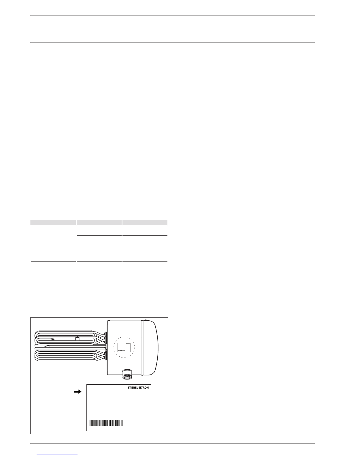
If you cannot remedy the fault, notify your heating contractor. To
facilitate and speed up your enquiry, please provide the serial
number from the type plate (no. 000000-0000-000000):
FCR Nr.: 000000 - 0000 - 000000
Made in Germany
FCR Nr.: 000000 - 0000 - 000000
Made in Germany
26�02�79�0076
Page 5

www.stiebel-eltron.com FCR 28 Si | 15
ENGLISH
INSTALLATION
Safety
INSTALLATION
7. Safety
Only a qualified contractor should carry out installation, commissioning, maintenance and repair of the appliance.
7.1 General safety instructions
We guarantee trouble-free function and operational reliability
only if the original accessories and spare parts intended for the
appliance are used.
7.2 Instructions, standards and regulations
Note
Observe all applicable national and regional regulations
and instructions.
7.3 Water connection and safety assembly
Note
Carry out all water connection and installation work in
accordance with regulations.
The cylinder must be connected with water inlet and outlet pipes
made from metal. Other metal parts of the cylinder that can be
touched and that are in contact with water must be permanently
and reliably connected with the earth conductor.
The max. permissible pressure must not be exceeded (see chapter
"Specification/ Data table").
Install a type-tested safety valve in the cold water supply
line. For this bear in mind that, depending on the static pressure, you may also need a pressure reducing valve.
Size the drain so that water can drain off unimpeded when
the safety valve is fully opened.
Fit the discharge pipe of the safety valve with a constant
downward slope and in a room free from the risk of frost.
The safety valve discharge aperture must remain open to the
atmosphere.
8. Appliance description
8.1 Standard delivery
Delivered with the appliance:
- 12 screws M14x35
- Cable entries (supplied as loose parts depending on the appliance type)
8.2 Accessories
Required accessories
Depending on the static pressure, safety assemblies and pressure
reducing valves are available. These type-tested safety assemblies
protect the appliance against unacceptable excess pressure.
Further accessories
A mating flange is available as an accessory.
9. Installation
Note
For the installation of the appliance, the cylinder must
be fitted with a mating flange (see chapter "Appliance
description / Accessories").
Note
The control panel must not be thermally insulated to prevent any excessively high temperatures from occurring
inside the control panel.
The condensate aperture in the flanged control panel
must remain open while the cylinder is thermally insulated so that any condensate that occurs can drip off freely.
Observe the required torque values during installation (see
chapter "Specification / Data table").
Always install the appliance horizontally with the cable en-
tries facing downwards.
Always install the appliance with heating elements and a
protective pipe arranged in parallel. For this, use the screws
supplied. Realign the components where necessary.
Page 6

16 | FCR 28 Si www.stiebel-eltron.com
INSTALLATION
Commissioning
9.1 Power connection
WARNING Electrocution
Carry out all electrical connection and installation work
in accordance with relevant regulations.
WARNING Electrocution
The connection to the power supply is only permissible
as a permanent connection in conjunction with the removable cable entry. Ensure that the appliance can be
separated from the power supply by an isolator that disconnects all poles with at least 3mm contact separation.
WARNING Electrocution
Ensure that the appliance is earthed.
!
Material losses
Observe the type plate. The specified voltage must match
the mains voltage.
Undo the screws at the bottom of the control panel cover and
remove the cover.
100
200
26�02�79�0049
Select a cable of the cross-sectional area suited to the load
of the appliance. Prepare the power cable, ensuring that the
earth conductor is longer than the other conductors.
Feed the power cable through the cable entry into the control
panel.
Connect the required load in accordance with the wiring
diagrams (see chapter "Specification/ Wiring diagrams and
connections").
Fit the control panel cover.
!
Material losses
Contactors for thermostats or high limit safety cut-outs
must be installed outside the control panel of the flanged
immersion heater. The contactors must be switched independently of one another by the thermostats and the high
limit safety cut-out respectively (see chapter "Specification/ Wiring diagrams and connections").
If the appliance is operated with power-OFF control, you must
install the power-OFF contact between the contactors or upstream
of the contactor.
Required contactor breaking capacity:
Sizing in accordance with the connected load (see chapter
"Specification/ Data table") for l
e
/ AC-1 / 70°C (thermal constant current with a resistive load at an ambient temperature of
up to 70°C).
Label the contactors according to their function.
If required, mark any live components inside the control
panel that are supplied with power from outside.
Once connected, check that the contactors are functioning
properly.
10. Commissioning
10.1 Commissioning
Fill the system with water.
!
Material losses
Boiling dry destroys the thermostat, which must then
be replaced. The high limit safety cut-out must be reset.
!
Material losses
If an indirect coil is installed in the same cylinder, limit
the maximum temperature for this appliance to the maximum temperature for the flanged immersion heater. This
prevents the high limit safety cut-out of the flanged immersion heater from responding.
Appliance handover
Explain the appliance function to users and familiarise them
with its operation.
Make users aware of potential dangers.
Hand over these instructions.
10.2 Recommissioning
See chapter "Commissioning".
Page 7

www.stiebel-eltron.com FCR 28 Si | 17
ENGLISH
INSTALLATION
Settings
11. Settings
Temperature
85°C
60°C
35°C
26�02�79� 0028
The temperature can be freely adjusted.
Factory setting 60°C (the temperature selector clicks into
place at this setting).
11.1 Limiting the temperature selection
Appliance type with external temperature selector
You can adjust the temperature selection limitation beneath the
temperature selector.
Factory setting: 60°C
Set the temperature selector to "cold" and isolate the appli-
ance from the power supply.
Remove the temperature selector and the control panel
cover.
Loosen the two screws from the outside and pull the thermo-
stat down to remove.
Once you have removed the limiter disc from the thermostat
axis, the maximum temperature can be reached.
Tighten the thermostat screws again and replace the tem-
perature selector and control panel cover.
12. Troubleshooting
Fault Cause Remedy
The water does not
heat up.
The high limit safety cutout has responded because
the controller is faulty.
Replace the thermostat and
press the high limit safety
cut-out reset button.
The high limit safety cutout has responded because
the temperature has fallen
below -15°C.
Press the reset button.
A heating element is faulty. Replace the heating ele-
ment or flanged immersion
heater.
The high limit safety cutout has responded because
an indirect coil in the same
cylinder is set too high.
Limit the maximum temperature of the indirect
coil.
The safety valve drips
when the heating is
switched off.
The valve seat is contaminated.
Clean the valve seat.
1
26�02�79�0015
1 High limit safety cut-out reset button
13. Maintenance
WARNING Electrocution
Before any work on the appliance, disconnect all poles
from the power supply.
13.1 Checking the safety assembly
Check the safety assembly regularly.
13.2 Descaling the flanged immersion heater
Descale the flanged immersion heater only after it has been
removed.
13.3 Replacing the heating elements and protective
pipe
When installing heating elements or a protective pipe, en-
sure that the components are electrically isolated from the
flange.
Page 8

18 | FCR 28 Si www.stiebel-eltron.com
INSTALLATION
Specication
14. Specification
14.1 Dimensions, immersion depths and connections
FCR 28/120 Si | FCR 28/180 Si | FCR 28/270 Si |
FSR 28/90 | FSR 28/180
325
280
225
D0000020344
1 2
FCR 28/360 Si
280
450
225
D0000020345
1 2
1 Entry electrical cables PG 13.5
2 Entry electrical cables PG 21
Mating flange
245
Ø 219
Ø 205
83
14
280
26�02�79�0013
14.2 Wiring diagrams and connections
FCR 28/120 Si, part number 075140
FCR 28/180 Si, part number 075131
12, 18 kW, 3/PE ~ 400 V
5
L3L2
L1
4
85�02�79�0001
4
5
3
1
2
1 Heating element
12 kW connected load: 6 x 2 kW
18 kW connected load: 6 x 3 kW
2 High limit safety cut-out
3 Thermostat
4 Contactor, installed by the heating contractor
5 Power-OFF contact, installed by the heating contractor
Page 9

www.stiebel-eltron.com FCR 28 Si | 19
ENGLISH
INSTALLATION
Specication
FCR 28/270 Si, part number 075141
FCR 28/360 Si, part number 075124
FSR 28/90, part number 004817
FSR 28/180, part number 004785
9, 18, 27, 36 kW, 3/PE ~ 400 V
6
5
4
L3L2
L1
4
5
3
1
2
85�02�79� 0002
1 Heating element
9 kW connected load: 9 x 1 kW
18 kW connected load: 9 x 2 kW
27 kW connected load: 9 x 3 kW
36 kW connected load: 9 x 4 kW
2 Thermostat
3 High limit safety cut-out
4 Contactor, installed by the heating contractor
5 Power-OFF contact, installed by the heating contractor
!
Material losses
When connecting the contactors, please observe chapter
"Installation / Power connection".
Page 10

20 | FCR 28 Si www.stiebel-eltron.com
INSTALLATION | GUARANTEE | ENVIRONMENT AND RECYCLING
14.3 Data table
FCR 28/120 Si FCR 28/180 Si FCR 28/270 Si FCR 28/360 Si FSR 28/ 90 FSR 28/180
075140 075131 075141 075124 004817 004785
Electrical data
Connected load ~ 400 V kW 12 18 27 36 9 18
Connected load ~ 380 V kW 10.8 16.4 24.4 32.6 8.2 16.4
Rated voltage V 400 400 400 400 400 400
Phases 3/PE 3/PE 3/PE 3/PE 3/PE 3/PE
Frequency Hz 50/60 50/60 50/60 50/60 50/60 50/60
Single circuit operating mode X X X X X
Application limits
Temperature setting range °C 35-85 35-85 35-85 35-85 35-85 35-85
Max. permissible pressure MPa 1 1 1 1 1.0 1.0
Minimum cylinder diameter mm 450 450 450 550 550 550
Minimum cylinder volume l 200 200 200 300 300 300
Versions
IP rating IP24 IP24 IP24 IP24 IP24 IP24
Dimensions
External flange diameter mm 280 280 280 280 280 280
Immersion depth mm 325 325 325 450 450 450
Torque Nm 80 80 80 80 80 80
Weights
Weight kg 13 13 14.8 17.7 15 15
Guarantee
The guarantee conditions of our German companies do not
apply to appliances acquired outside of Germany. In countries
where our subsidiaries sell our products a guarantee can only
be issued by those subsidiaries. Such guarantee is only granted if the subsidiary has issued its own terms of guarantee. No
other guarantee will be granted.
We shall not provide any guarantee for appliances acquired in
countries where we have no subsidiary to sell our products.
This will not aect warranties issued by any importers.
Environment and recycling
We would ask you to help protect the environment. After use,
dispose of the various materials in accordance with national
regulations.
ENVIRONMENT AND RECYCLING
Page 11

Deutschland
STIEBEL ELTRON GmbH & Co. KG
Dr.-Stiebel-Straße 33 | 37603 Holzminden
Tel. 05531 702-0 | Fax 05531 702-480
info@stiebel-eltron.de
www.stiebel-eltron.de
Verkauf Tel. 05531 702-110 | Fax 05531 702-95108 | info-center@stiebel-eltron.de
Kundendienst Tel. 05531 702-111 | Fax 05531 702-95890 | kundendienst@stiebel-eltron.de
Ersatzteilverkauf Tel. 05531 702-120 | Fax 05531 702-95335 | ersatzteile@stiebel-eltron.de
Irrtum und technische Änderungen vorbehalten! | Subject to errors and technical changes! | Sous réserve
d‘erreurs et de modifications techniques! | Onder voorbehoud van ver
g
issingen en technische wijzigingen! |
Salvo error o modificación técnica! | Excepto erro ou alteração técnica | Zastrzeżone zmian
y
techniczne i
ewentualne błędy | Omyly a technické změny jsou vyhrazeny! | A muszaki változtatások és tévedések jogát
fenntartjuk! |
Отсутствие ошибок не гарантируется. Возможны технические изменения.
| Chyby a
technické zmeny sú vyhradené! Stand 9046
Australia
STIEBEL ELTRON Australia Pty. Ltd.
6 Prohasky Street | Port Melbourne VIC 3207
Tel. 03 9645-1833 | Fax 03 9645-4366
info@stiebel.com.au
www.stiebel.com.au
Austria
STIEBEL ELTRON Ges.m.b.H.
Eferdinger Str. 73 | 4600 Wels
Tel. 07242 47367-0 | Fax 07242 47367-42
info@stiebel-eltron.at
www.stiebel-eltron.at
Belgium
STIEBEL ELTRON bvba/sprl
't Hofveld 6 - D1 | 1702 Groot-Bijgaarden
Tel. 02 42322-22 | Fax 02 42322-12
info@stiebel-eltron.be
www.stiebel-eltron.be
China
STIEBEL ELTRON (Guangzhou) Electric
Appliance Co., Ltd.
Rm 102, F1, Yingbin-Yihao Mansion, No. 1
Yingbin Road
Panyu District | 511431 Guangzhou
Tel. 020 39162209 | Fax 020 39162203
info@stiebeleltron.cn
www.stiebeleltron.cn
Czech Republic
STIEBEL ELTRON spol. s r.o.
K Hájům 946 | 155 00 Praha 5 - Stodůlky
Tel. 251116-111 | Fax 235512-122
info@stiebel-eltron.cz
www.stiebel-eltron.cz
Finland
STIEBEL ELTRON OY
Kapinakuja 1 | 04600 Mäntsälä
Tel. 020 720-9988
info@stiebel-eltron.fi
www.stiebel-eltron.fi
France
STIEBEL ELTRON SAS
7-9, rue des Selliers
B.P 85107 | 57073 Metz-Cédex 3
Tel. 0387 7438-88 | Fax 0387 7468-26
info@stiebel-eltron.fr
www.stiebel-eltron.fr
Hungary
STIEBEL ELTRON Kft.
Gyár u. 2 | 2040 Budaörs
Tel. 01 250-6055 | Fax 01 368-8097
info@stiebel-eltron.hu
www.stiebel-eltron.hu
Japan
NIHON STIEBEL Co. Ltd.
Kowa Kawasaki Nishiguchi Building 8F
66-2 Horikawa-Cho
Saiwai-Ku | 212-0013 Kawasaki
Tel. 044 540-3200 | Fax 044 540-3210
info@nihonstiebel.co.jp
www.nihonstiebel.co.jp
Netherlands
STIEBEL ELTRON Nederland B.V.
Daviottenweg 36 | 5222 BH 's-Hertogenbosch
Tel. 073 623-0000 | Fax 073 623-1141
info@stiebel-eltron.nl
www.stiebel-eltron.nl
Poland
STIEBEL ELTRON Polska Sp. z O.O.
ul. Działkowa 2 | 02-234 Warszawa
Tel. 022 60920-30 | Fax 022 60920-29
biuro@stiebel-eltron.pl
www.stiebel-eltron.pl
Russia
STIEBEL ELTRON LLC RUSSIA
Urzhumskaya street 4,
building 2 | 129343 Moscow
Tel. 0495 7753889 | Fax 0495 7753887
info@stiebel-eltron.ru
www.stiebel-eltron.ru
Slovakia
TATRAMAT - ohrievače vody s.r.o.
Hlavná 1 | 058 01 Poprad
Tel. 052 7127-125 | Fax 052 7127-148
info@stiebel-eltron.sk
www.stiebel-eltron.sk
Switzerland
STIEBEL ELTRON AG
Industrie West
Gass 8 | 5242 Lupfig
Tel. 056 4640-500 | Fax 056 4640-501
info@stiebel-eltron.ch
www.stiebel-eltron.ch
Thailand
STIEBEL ELTRON Asia Ltd.
469 Moo 2 Tambol Klong-Jik
Amphur Bangpa-In | 13160 Ayutthaya
Tel. 035 220088 | Fax 035 221188
info@stiebeleltronasia.com
www.stiebeleltronasia.com
United Kingdom and Ireland
STIEBEL ELTRON UK Ltd.
Unit 12 Stadium Court
Stadium Road | CH62 3RP Bromborough
Tel. 0151 346-2300 | Fax 0151 334-2913
info@stiebel-eltron.co.uk
www.stiebel-eltron.co.uk
United States of America
STIEBEL ELTRON, Inc.
17 West Street | 01088 West Hatfield MA
Tel. 0413 247-3380 | Fax 0413 247-3369
info@stiebel-eltron-usa.com
www.stiebel-eltron-usa.com
A 296668-38920-9063
4<AMHCMN=jgggig>
 Loading...