

Page 1

.CeC&eC.CZ`<<`.HC
HTV`.C&C.CZ`<<`.HC
:<é%VC.CeC&%iVeV+<e%V+.`xV+ĜÄéŝŌZ<<VBH`HC`VH<
%HV.CZ`C`CHeZq`V+`VZ+ĜÄéŝŌZ<
á %ĜZ<
HOHFWURQLF FRPIRU
W
Page 2
2
A
2x
electronic comfort
1
26_02_02_0704
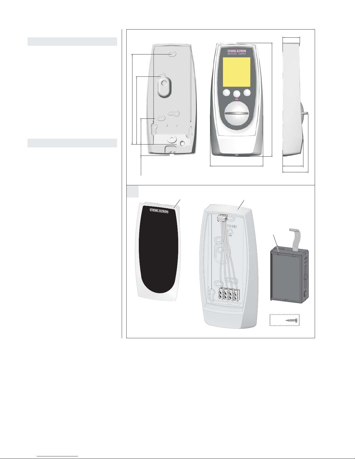
150 mm
190 mm
113 mm
43 mm
88 mm 34 mm
29 mm
43 mm
19 mm
2
3
26_02_02_0710
Inhaltsverzeichnis
Deutsch Seite 4 - 5
1. Gebrauchsanweisung 4
1.1 Beschreibung
1.2 Bedienung
1.3 Sicherheitshinweise
1.4 Pflege
2. Montageanweisung 4
2.1 Vorschriften und Bestimmungen
2.2 Montageort
2.3 Anschlusskabel für FB 1 SL
2.4 Umbau Durchlauferhitzer
2.5 Bedienteilmontage
Erstinbetriebnahme 5
Ersatzteile 5
Table of contents
English page 6 - 7
1. Operating instructions 6
1.1 Description
1.2 Operation
1.3 Safety informations
1.4 Care
2. Installation instructions 6
2.1 Regulations and specifications
2.2 Installation location
2.3 Connecting cable for FB 1 SL
2.4 Converting instantaneous
2.5 Remote control installation
Initial Operation 7
Spare Parts 7
Page 3
3
Adapter
H
electroniccomfort
1
F
G
C
D
E
B
elect
r
o
nic
com
for
t
26_02_02_0715
26_02_02_0543
26_02_02_0707
e
l
e
ctr
o
nic
com
for
t
4
5
8
electr
o
nic
comfort
7
6
6
10
9
26_02_02_0688
3
26_02_02_0598
12
11
26_02_02_0686
300
35
6
t 300 mm
35 mm
6 mm
26_02_02_0276 26_02_02_0703
Page 4

4
Zur Montage der Kabel-Fernbedienung gehören der Wechsel des Bedienteiles vom
DHE zum Wandhalter sowie der Aufbau der
Datenübertragung mittels Telefonkabel und
Adapterbaugruppe.
2.1 Vorschriften und Bestimmungen
• Einbau und Erstinbetriebnahme der FB 1 SL
muss von einem Fachmann unter Beachtung
dieser Montageanweisung durchgeführt
werden.
• Die Gebrauchs- und Montageanweisung des
Durchlauferhitzers ist bei der Installation und
Bedienung zu beachten.
• Alle elektrischen Anschluss- und Installations arbeiten sind nach den VDE-Bestimmungen (0100), den Vorschriften
des zuständigen EVU’s sowie den entsprechenden nationalen und regionalen Vorschriften auszuführen.
•
Ein installiertes Gerätes ist vor dem Nachrüsten mit einer Fernbedienung spannungsfrei zu schalten.
• Zum Schutz gegen eindringendes Wasser
sind die am Gerät vorhandenen Kabelabdichtungen einzusetzen.
• Nur bei montierter Blende (1) im Durch-
lauferhitzer ist weiter hin die Schutzart IP 25
(strahlwassergeschützt) gewährleistet.
• Die länderspezifischen Vorschriften sind zu
beachten.
2.2 Montageort
Die Fernbedienung wird mit Hilfe des Wandhalters an einem gut zugänglichem Ort
montiert.
Die Anbringung im Schutzbereich 1 (Anforderung IP X4 oder IP X5) ist möglich.
Montage auf einer Unterputz-Schalterdose
oder Aufputz-Montage.
Die Nutzung elektrischer Geräte muss grundsätzlich mit der gebotenen Vorsicht erfolgen,
um ein potenzielles Risiko durch Feuer,
elektrischen Stromschlag oder Verletzung auszuschließen. Daher ist das Gerät nur wie in
dieser Anweisung beschrieben zu nutzen. Jeder
Gebrauch außerhalb der Herstellerem pfehlung
kann zu Schäden oder Verletzungen führen.
Vor Gebrauch des Gerätes ist die gesamte Anweisung zu lesen und die enthaltenen Hinweise
zum sachgemäßen Umgang mit dem Gerät
sind zu befolgen.
!
Diese Anweisung sorgfältig auf-
bewahren, bei Besitzerwechsel des
Gerätes dem Nachfolger aushändigen.
Bei etwaigen Instandsetzungsarbeiten dem
Fachmann zur Einsicht überlassen.
1. Gebrauchsanweisung für den Benutzer und den Fachmann
1.1 Beschreibung
FB 1 SL ist ein Bausatz zur Installation einer Kabel-
Fernbedienung für die Stiebel Eltron Durchlauferhitzer DHE 18 - 27 SL(i) electronic comfort ab
Baujahr Mai 2005.
Der „Bausatz Kabel-Fernbedienung“ enthält
die notwendigen Bauteile, um das Bedienteil
aus der Gerätekappe des DHE .. SL an eine
externe Stelle in Küche oder Badezimmer zu
verlegen. Hierzu wird das Bedienteil aus der
Gerätekappe ausgebaut und in die Wandhalterung des Bausatzes eingesetzt.
Zur Datenübertragung zwischen Fernbedienung und Durchlauferhitzer wird die
Adapter baugruppe des Bausatzes in den
Durchlauf erhitzer eingebaut und über ein
Kabel mit der Fernbedienung verbunden.
In die DHE-Gerätekappe wird die Blende des
Bausatzes eingesetzt.
Lieferumfang FB 1 SL
A
:
• Blende (1) für DHE-Gerätekappe
• Wandhalter (2) zur Aufnahme des Bedien-
teiles vom DHE.
• Adapterbaugruppe (3)
• Befestigungsmaterial zur Montage auf Unter-
putz-Schalterdose
1.2 Bedienung
!
Die Funktionen des Bedienteils entnehmen Sie bitte der Gebrauchs- und
Montageanweisung des Durchlauferhitzers.
1.3 Sicherheitshinweise
• Es dürfen keinerlei Änderungen an der
Fernbedienung vorgenommen werden.
• Ist ein Bauteil beschädigt, die Fernbedienung heruntergefallen oder es lag
bereits eine Fehlfunktion vor, ist die Fernbedienung nicht in Betrieb zu nehmen.
1.4 Pflege
Zur Pflege des Gehäuses genügt ein feuchtes
Tuch. Keine scheuernden oder lösenden
Reinigungsmittel verwenden.
2. Montageanweisung für den Fachmann
Eine Montage im Strahlbereich der Handbrause ist zu vermeiden.
2.3 Anschlusskabel für FB 1 SL
Die Fernbedienung wird mit Sicherheitskleinspannung betrieben. Eine einwandfreie
Kommunikation ist bis zu einer Anschlusslänge von 15 m gewährleistet.
Steuerleitung:
Telefonleitung Typ J-YY 2x2x0,6
(ohne metallische Abschirmung).
Eine festverlegte Auf- oder Unterputz-Verlegung der Steuerleitung ist zulässig.
Im Schutzbereich 1 dürfen keine abgeschirmten
Kabel verwendet werden.
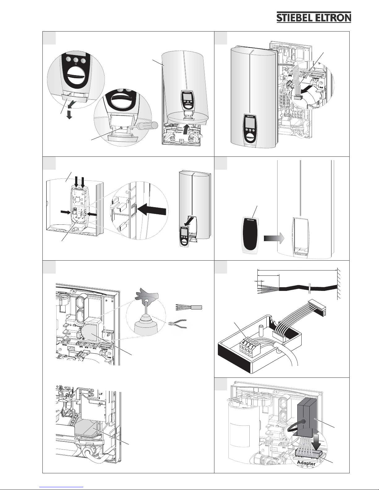
2.4 Umbau Durchlauferhitzer
–
B
Abdeckklappe am Durchlauferhitzer
öffnen (4), Befestigungsschraube lösen (5),
Gerätekappe (6) abnehmen.
–
C
Stecker des Sollwertgeberkabels (7) vom
Durchlauferhitzer abziehen.
–
D
Bedienteil (8) aus Gerätekappe (6) ent-
nehmen, dazu die 4 Rasthaken drücken.
–
E
Blende (1) in Gerätekappe eindrücken,
dabei müssen alle 4 Rasthaken einrasten.
!
Eine Blende mit beschädigten Rasthaken darf nicht eingebaut werden!
2.4.1 Elektrischer Anschluss am Durchlauferhitzer
F
Anschlusskabel wahlweise durch die freie
Kabeltülle oben (9) oder unten (10) führen.
Bei Anschluss durch die obere Kabeltülle (9)
ist diese am Kegel entsprechend des Kabelquerschnitts abzuschneiden.
Bei Anschluss durch die untere Kabeltülle
(10) ist das Kabel im Gerät unter den Kabelhalterungen am Kupferbehälter (Heizkörper)
entlang nach oben zu verlegen.
Adapterbaugruppe montieren
G
– Anschlusskabel 35 mm abmanteln und
Kabelenden 6 mm abisolieren.
– Gehäuse der Adapterbaugruppe durch Ein-
drücken zweier seitlicher Schnapphaken öffnen.
– Anschlusskabel an Klemmleiste (11) an-
schließen, in Kabeldurchführung legen und
Gehäuse wieder schließen.
–
H
Stecker (12) auf Steckplatz „Adapter“
stecken und Adapterbaugruppe rechts oben
in die Geräte rückwand einsetzen.
2.5 Montage Fernbedienung
2.5.1 Bedienteilmontage
–
I
Zweiteiligen Wandhalter (2) auseinander nehmen, hierzu die unten sitzende
Schraube (17) lösen.
– Buchsenklemmen-Baugruppe (13) vom
Wandhalter-Unterteil abziehen.
–
J
Platine (14) aus Bedienteil lösen.
Hierzu die Platine am unteren Steg mit dem
Daumen leicht hochziehen und dabei nacheinander die drei rechten Rasthaken lösen.
– K Sollwertgeberkabel (7) an der Platine
durch Buchsenklemmen-Baugruppe (13) aus
dem Wandhalter ersetzen.
– Platine wieder in das Bedienteil einsetzen.
Hierzu die Platine zuerst links einsetzen,
dann rechts herunterdrücken.
Dabei auf korrekte Positionierung der
Regler achse und der Mitnehmernase des
Drehknopfes achten (sonst keine korrekte
Montage möglich).
–
L
Bedienteil in das Oberteil des Wandhalters eindrücken, alle 4 Rasthaken müssen
einrasten.
2.5.2 Montage Wandhalter-Unterteil
. . . bei Aufputzmontage des Anschlusskabels
–
M
Ausbrüche zur Kabeldurchführung (15)
unten am Wand halter ausbrechen
Page 5

5
Ersatzteile
Auszug aus der Ersatzteilliste
Erstinbetriebnahme
für den Fachmann
Der Durchlauferhitzer DHE . . SL(i)
mit der Fernbedienung FB 1 SL ist
unter Berücksichtigung der Gebrauchs- und
Montageanweisung des Durchlauferhitzers
in Betrieb zu nehmen:
– „Montage abschließen“
– „Erstinbetriebnahme“.
(2 Ausbruchstellen Wand halter-Unterteil, 1
Ausbruchstelle Wandhalter-Oberteil).
– Anschlusskabel durch die Kabeldurch-
führung und die Kabelabdichtung (16)
führen.
–
N
Wandhalter mit geeigneten Befestigungsmaterial durch die beiden
Ausbruchstellen
a
befestigen.
Bei Austausch gegen eine ältere Fernbedienung sind in dem Wandhalter entsprechende Ausbrüche
b
vorgesehen.
. . . bei Montage auf Unterputz-Schalterdose
– Anschlusskabel durch die Kabelabdichtung
(16) führen.
–
N
Wandhalter durch die für Schalterdosen
passenden Ausbrüche
c
mit beiliegenden
Schrauben befestigen.
PON
MLK
JI
a
26_02_02_0709
13
14
7
13
15
b
b
a
c
c
16
2
17
26_02_02_0702
26_02_02_0705
26_02_02_0706
26_02_02_0708
26_02_02_0711
26_02_02_0713
26_02_02_0714
26_02_02_0716
26_02_02_0717
Benennung Best.-Nr.
Blende (1).....................270777
Wandhalter (2) .................270778
Adapterbaugruppe (3)............270779
!
2.5.3 Elektrischer Anschluss der Fernbedienung
– Anschlusskabel 35 mm abmanteln und
Kabelenden 6 mm abisolieren.
–
O
Buchsenklemme auf die Stege am
Wand halter-Unterteil stecken und das Wandhalter-Oberteil in Parkposition platzieren.
–
P
Anschlusskabel an Buchsenklemme
anklemmen, hierbei die Klemmreihenfolge
(1, 2, 3, 4) in der Adapterbaugruppe beachten.
– Wandhalter-Oberteil oben am Unterteil ein-
hängen, herunterklappen und festschrauben.
Aussagen zu:
„Umwelt, Recycling, Kundendienst und
Garantie“ siehe Gebrauchs- und Montage-
anweisung des Durchlauferhitzers.
Deutsch
Page 6

6
Installation of the cable remote control includes a change of the control unit from the
DHE to the wall mount and the fitting of the
data transfer by telephone cable and connection module.
2.1 Regulations and specifications
• The FB 1 SL connection module must be
fitted and initially started up by a qualified
installer, following these installation instructions.
• The operating and installation instructions
for the instantaneous water heater must be
observed on installation and operation.
• All electrical connections and installation
work will be carried out in accordance with
the VDE Rules (0100), the provisions of the
electrical associations concerned and the appropriate national and regional regulations.
• An installed unit will be switched off before
retrofitting with a remote control.
• The cable seals supplied with the unit will
be fitted as protection against penetrating
water.
• Protection class IP 25 (spray water protected) is achieved only after the cover (1) has
been installed on the heater.
• The regulations specific to the country will
be observed.
2.2 Installation location
The remote control is fitted at a clearly accessible spot with the aid of the wall mount. They
can be fitted in protection class 1 (IP X4 or
IP X5). Assembly on a concealed switchbox or
surface-mounted assembly.
Installation in an area subject to spray water
from a hand-held shower is to be avoided.
Electrical equipment must in principle be used
with due care to eliminate any potential risk
through fire, electric shock or injury. The unit
should therefore be used only as described
in these instructions. Use disregarding the
manufacturer‘s recommendations may result
in damage or injury.
The instructions should be read carefully
throughout before using the appliance and the
advice given on proper handling of the unit
should be followed.
!
Keep these instructions in a safe place
and give them to the new owner if you
move house. If maintenance or repair work is
required, let the qualified installer have them
for reference.
1. Operating instructions for the user and installer
1.1 Description
FB 1 SL is a module for installing a cable re-
mote control for the Stiebel Eltron Instantaneous Water Heater DHE 18-27 SL(i) electronic
comfort built from May 2005.
The cable remote control consists of the control panel for the instantaneous water heater
and the wall mount for the module. The control panel is removed from the unit cover and
inserted in the wall mount for the module. The
remote control is installed at any desired place
in the kitchen or bathroom.
The module connecting assembly built into the
instantaneous water heater and linked to the
remote control by a cable serves to transfer data
between the remote control and heater.
The module panel is fitted into the DHE cover.
Scope of supply FB 1 SL
A
:
• Cover (1) for the DHE unit cover
• Wall mount (2) to take the DHE control unit.
• Connection module (3)
• Fastening material for installation on the
concealed switchbox.
1.2 Operation
!
Please see the operating and installation instructions for the instantaneous
water heater for using the control unit.
1.3 Safety information
• No changes of any kind may be made to the
remote control.
• The remote control must not be used if a
component is damaged, the remote control
has fallen down or it was already malfunctioning.
1.4 Care
A damp cloth is all that is needed to care for
the housing. Don‘t use abrasive or aggressive
cleaning agents.
2. Installation instructions for the qualified installer
2.3 Connecting cable for FB 1 SL
The remote control operates on safety extralow voltage. Connections up to 15 m in length
are ensured for easy communication.
Control line:
Telephone line type J-YY 2x2x0.6
(without metallic screening)
The control line can be laid permanently concealed or surface-mounted.
Screened cables may not be used under protection class 1.
2.4 Converting instantaneous water heaters
–
B
open the cover on the heater (4), loosen
the retaining screw (5). Remove the cover (6).
–
C
pull the plug for the thermostat fly lead
cable from the heater.
– D remove the control unit (8) from the
cover (6), pressing the 4 engagement hooks.
–
E
press the panel (1) into the cover, lodg-
ing on all 4 engagement hooks.
!
Don‘t fit a panel with damaged engagement hooks.
2.4.1 Electrical connection to the instantaneous water heater
F
Feed the connecting cable optionally
through the top (9) or bottom (10) available
cable grommet. When connecting through the
upper cable grommet (9), it must be cut back at
the bevel in line with the cable cross section.
When connecting through the bottom cable
grommet (10), the cable must be laid in the
unit beneath the cable holders on the copper
tank (heater).
Installing the connection module
G
– Strip the connecting cable for 35 mm and
insulate the cable ends for 6 mm.
– Open the connecting module housing by
pressing in two of the catches on the side.
– Connect the connecting cable to the termi-
nal strip (11), place in the cable bushing
and re-close the housing.
–
H
insert the plug (12) into the „adapter“
point and place the connection module
against the unit back wall top right.
2.5 Remote control installation
2.5.1 Control unit installation
–
I
disassemble the two-part wall mount (2),
by loosening the screws at the bottom (17).
– pull the terminal strip component (13) from
the lower part of the wall mount.
– J loosen the motherboard (14) from the
control unit. Do so by pulling the board
upwards with the thumbs at the bottom
connector, loosening the three right-hand
engagement hooks one after the other at
the same time.
–
K
replace the thermostat fly lead cable (7)
on the motherboard with the terminal strip
component (13) from the wall mount.
– Reinsert the motherboard in the control unit,
doing so by first inserting the motherboard
on the left then pressing down to the right.
Check the correct positioning of the unit
centre line and drive lug on the knob (correct
installation is not otherwise possible).
–
L
Press the control unit into the upper part
of the wall mount. All 4 engagement hooks
must nest.
2.5.2 Assembly of wall mount lower part
… on surface-mounted assembly of the connecting cable
–
M
punch out the knock-out points for the
cable bushing (15) at the bottom of the wall
mount (2 wall mount lower part knock-out
points, 1 wall mount upper part knock-out
point).
Page 7

7
PON
MLK
JI
a
26_02_02_0709
13
14
7
13
15
b
b
a
c
c
16
2
17
26_02_02_0702
26_02_02_0705
26_02_02_0706
26_02_02_0708
26_02_02_0711
26_02_02_0713
26_02_02_0714
26_02_02_0716
26_02_02_0717
Spare Parts
excerpt from the Parts List
Initial Operation
for the qualified installer
For starting up the instantaneous wa-
ter heater DHE .. SL(i) with the remote
control FB 1 SL, please note the Instantaneous Water Heater Operating and Installation
Instructions:
– „Completion of installation“
– „Initial Operation“.
Nomenclature Order No.
Cover Panel (1) .................270777
Wall mount (2) .................270778
Connection module (3) ...........270779
– Feed the connecting cable through the cable
bushings and cable seal (16).
–
N
fasten the wall mount with suitable fastening material through the two knock-out
points
a
.
The wall mount includes appropriate knockout points
b
for replacing an older remote
control.
… for assembly on concealed switchbox
– feed the connecting cable through the cable
seal (16).
–
N
fasten the wall mount with the screws
supplied through the knock-out points
c
appropriate to the switchboxes.
!
2.5.3 Remote control electrical connection
– Strip the connecting cable for 35 mm and
insulate the cable ends for 6 mm.
–
O
insert the terminal strip on the connectors in the wall mount lower part and position the wall mount upper part in parking
position.
–
P
fasten the connecting cable to the terminal strip, noting the sequence of terminal
rows (1, 2, 3, 4) in the connection module.
– Slot the wall mount upper part into the lower
part at the top, fold down and screw tight.
Information on:
„Environment, recycling, after-sales service
and guarantee“ see Instantaneous Water Heater
Operating and Installation Instructions.
English
Page 8

Deutschland
STIEBEL ELTRON GmbH & Co. KG
Dr.-Stiebel-Straße | 37603 Holzminden
Tel. 05531 702-0 | Fax 05531 702-480
info@stiebel-eltron.de
www.stiebel-eltron.de
Verkauf Tel. 05531 702-110 | Fax 05531 702-95108 | info-center@stiebel-eltron.de
Kundendienst Tel. 05531 702-111 | Fax 05531 702-95890 | kundendienst@stiebel-eltron.de
Ersatzteilverkauf Tel. 05531 702-120 | Fax 05531 702-95335 | ersatzteile@stiebel-eltron.de
Irrtum und technische Änderungen vorbehalten! | Subject to errors and technical changes! | Sous réserve
d‘erreurs et de modifications techniques! | Onder voorbehoud van ver
g
issingen en technische wijzigingen! |
Salvo error o modificación técnica! | Excepto erro ou alteração técnica | Zastrzeżone zmian
y
techniczne i
ewentualne błędy | Omyly a technické změny jsou vyhrazeny! | A muszaki változtatások és tévedések jogát
fenntartjuk! |
Отсутствие ошибок не гарантируется. Возможны технические изменения.
| Chyby a
technické zmeny sú vyhradené! Stand 8770
Australia
STIEBEL ELTRON Australia Pty. Ltd.
4/8 Rocklea Drive | Port Melbourne VIC 3207
Tel. 03 9645-1833 | Fax 03 9645-4366
info@stiebel.com.au
www.stiebel.com.au
Austria
STIEBEL ELTRON Ges.m.b.H.
Eferdinger Str. 73 | 4600 Wels
Tel. 07242 47367-0 | Fax 07242 47367-42
info@stiebel-eltron.at
www.stiebel-eltron.at
Belgium
STIEBEL ELTRON bvba/sprl
't Hofveld 6 - D1 | 1702 Groot-Bijgaarden
Tel. 02 42322-22 | Fax 02 42322-12
info@stiebel-eltron.be
www.stiebel-eltron.be
Czech Republic
STIEBEL ELTRON spol. s r.o.
K Hájům 946 | 155 00 Praha 5 - Stodůlky
Tel. 251116-111 | Fax 235512-122
info@stiebel-eltron.cz
www.stiebel-eltron.cz
Denmark
Pettinaroli A/S
Mandal Allé 21 | 5500 Middelfart
Tel. 06341 666-6 | Fax 06341 666-0
info@stiebel-eltron.dk
www.stiebel-eltron.dk
Finland
Insinööritoimisto Olli Andersson Oy
Kapinakuja 1 | 04600 Mäntsälä
Tel. 020 720-9988 | Fax 020 720-9989
info@stiebel-eltron.fi
www.stiebel-eltron.fi
France
STIEBEL ELTRON SAS
7-9, rue des Selliers
B.P 85107 | 57073 Metz-Cédex 3
Tel. 0387 7438-88 | Fax 0387 7468-26
info@stiebel-eltron.fr
www.stiebel-eltron.fr
Hungary
STIEBEL ELTRON Kft.
Gyár u. 2 | 2040 Budaörs
Tel. 01 250-6055 | Fax 01 368-8097
info@stiebel-eltron.hu
www.stiebel-eltron.hu
Japan
NIHON STIEBEL Co. Ltd.
Kowa Kawasaki Nishiguchi Building 8F
66-2 Horikawa-Cho
Saiwai-Ku | 212-0013 Kawasaki
Tel. 044 540-3200 | Fax 044 540-3210
info@nihonstiebel.co.jp
www.nihonstiebel.co.jp
Netherlands
STIEBEL ELTRON Nederland B.V.
Daviottenweg 36
5222 BH 's-Hertogenbosch
Tel. 073 623-0000 | Fax 073 623-1141
stiebel@stiebel-eltron.nl
www.stiebel-eltron.nl
Poland
STIEBEL ELTRON Polska Sp. z o.o.
ul. Działkowa 2 | 02-234 Warszawa
Tel. 022 60920-30 | Fax 022 60920-29
stiebel@stiebel-eltron.pl
www.stiebel-eltron.pl
Russia
STIEBEL ELTRON LLC RUSSIA
Urzhumskaya street 4,
building 2 | 129343 Moscow
Tel. 0495 7753889 | Fax 0495 7753887
info@stiebel-eltron.ru
www.stiebel-eltron.ru
Slovakia
TATRAMAT - ohrievače vody, s.r.o.
Hlavná 1 | 058 01 Poprad
Tel. 052 7127-125 | Fax 052 7127-148
info@stiebel-eltron.sk
www.stiebel-eltron.sk
Switzerland
STIEBEL ELTRON AG
Industrie West
Gass 8 | 5242 Lupfig
Tel. 056 4640-500 | Fax 056 4640-501
info@stiebel-eltron.ch
www.stiebel-eltron.ch
Thailand
STIEBEL ELTRON Asia Ltd.
469 Moo 2 Tambol Klong-Jik
Amphur Bangpa-In | 13160 Ayutthaya
Tel. 035 220088 | Fax 035 221188
info@stiebeleltronasia.com
www.stiebeleltronasia.com
United Kingdom and Ireland
STIEBEL ELTRON UK Ltd.
Unit 12 Stadium Court
Stadium Road | CH62 3RP Bromborough
Tel. 0151 346-2300 | Fax 0151 334-2913
info@stiebel-eltron.co.uk
www.stiebel-eltron.co.uk
United States of America
STIEBEL ELTRON, Inc.
17 West Street | 01088 West Hatfield MA
Tel. 0413 247-3380 | Fax 0413 247-3369
info@stiebel-eltron-usa.com
www.stiebel-eltron-usa.com
A 270771-35707-8541
4<AMHCMN=hahhbf>
 Loading...