

STIEBEL ELTRON ETW 12, ETW 360, ETW 420, ETW 180, ETW 480 Operation And Installation
...
BEDIENUNG UND INSTALLATION
OPERATION AND INSTALLATION
UTILISATION ET INSTALLATION
BEDIENING EN INSTALLATIE
OBSLUHA A INSTALACE
Wand-Flachspeicher | Wall mounted slimline storage heater | Accumulateur plat
mural | platte wand-warmteaccumulator | Plochá nástěnná akumulační kamna
» ETW 120
» ETW 180
» ETW 240
» ETW 300
» ETW 360
» ETW 420
» ETW 480
OPERATION
!
!
!
GENERAL INFORMATION
OPERATION ��������������������������������������������24
1. General information ������������������������������������������ 24
1.1 Key ��������������������������������������������������������������������24
2. Safety ���������������������������������������������������������� 25
2.1 Correct use ���������������������������������������������������������� 25
2.2 Safety instructions ������������������������������������������������ 25
2.3 Safety clearances �������������������������������������������������� 25
2.4 CE designation ����������������������������������������������������� 25
3. Equipment description ��������������������������������������� 26
4. Operation ����������������������������������������������������� 26
4.1 User interface ������������������������������������������������������26
4.2 User interface fascia ���������������������������������������������� 26
4.3 Factory settings ���������������������������������������������������� 27
5. Cleaning, care and maintenance ���������������������������� 27
5.1 Cleaning the fluff filter ������������������������������������������� 27
6. What to do if... ������������������������������������������������ 28
INSTALLATION ����������������������������������������� 28
7. Safety ���������������������������������������������������������� 29
7.1 Country-specific safety information ���������������������������29
7.2 Instructions, standards and regulations ���������������������� 29
8. Equipment description ��������������������������������������� 29
8.1 Standard delivery ��������������������������������������������������29
8.2 Factory settings ���������������������������������������������������� 29
8.3 Design operation �������������������������������������������������� 29
8.4 Special accessories ������������������������������������������������ 29
9. Installation ���������������������������������������������������� 30
9.1 Installation conditions and preparation ����������������������30
10. Assembly ������������������������������������������������������ 31
10.1 Installation location ����������������������������������������������� 31
10.2 Installation versions ���������������������������������������������� 31
10.3 Installation ���������������������������������������������������������� 32
10.4 Inserting storage blocks �����������������������������������������34
10.5 Cleaning the appliance ������������������������������������������� 35
10.6 Closing the appliance ��������������������������������������������� 35
10.7 Power connection ������������������������������������������������� 36
11. Commissioning ������������������������������������������������ 36
11.1 Checks before commissioning ����������������������������������36
11.2 Commissioning �����������������������������������������������������36
11.3 Restarting ����������������������������������������������������������� 36
12. Handover ������������������������������������������������������ 36
13. Troubleshooting����������������������������������������������� 37
13.1 Status display for charge controller ���������������������������37
13.2 What to do if... ����������������������������������������������������� 37
13.3 Changing the fuse ������������������������������������������� 38
13.4 Symbols on the type plate ��������������������������������������� 38
14. Maintenance ��������������������������������������������������� 38
15. Specification ��������������������������������������������������� 39
15.1 Positioning ���������������������������������������������������������� 39
15.2 Reducing the connected load ����������������������������������� 40
15.3 Output matching (rated charge duration) �������������������� 41
15.4 Connection diagrams ��������������������������������������������� 42
15.5 Appliance wiring diagram ��������������������������������������� 43
1. General information
The chapter Operation is intended for users and contractors.
The chapter Installation is intended for contractors.
Please read carefully.
Read these instructions carefully before using the
appliance and retain them for future reference. If the
appliance is passed on to a third party please hand
these instructions to the new user.
1.1 Key
1.1.1 Symbols in these installation instructions:
In this documentation you will come across symbols and highlights
that are defined as follows:
Risk of injury!
Information concerning possible risks of injury for
installers or users, and potential equipment damage.
Danger of electrocution!
Risk of scalding.
Risk of damage.
Information regarding potential situations that bring a
risk with them that might occur during the appliance
installation or operation, the consequences of which
may be equipment damage, environmental pollution
or material loss.
Please read carefully.
Read this section carefully.
»Passages with this symbol "»" indicate step-by-step procedures
you must carry out.
— Passages with this symbol "
1.1.2 Symbols on the appliance
This symbol is defined as follows:
Appliance disposal
Appliances with this marking are not suitable for
general waste disposal, and should therefore be
disposed of separately.
Never cover the appliance
Never hang washing over the appliance to dry.
Fire hazard.
–" indicate lists.
CUSTOMER SERVICE AND WARRANTY ���������������44
ENVIRONMENT AND RECYCLING ���������������������� 44
24 |ETW 120, 180, 240, 300, 360, 420, 480 electronic www.stiebel-eltron.com
OPERATION
!
!
SAFETY
2. Safety
2.1 Correct use
This appliance is designed to heat living areas.
This appliance is designed for domestic use. It can be used safely
by untrained persons. The appliance can also be used in a nondomestic environment, e.g. in a small business, as long as it is
used in the same way.
Any other use beyond that described shall be deemed inappropriate.
Observation of these instructions is also part of the correct use of
this appliance. Any modifications or conversions to the appliance
void all warranty rights.
2.2 Safety instructions
Observe the following safety information and instructions.
Only qualified contractors should install and commission this
appliance.
The contractor is responsible for adherence to all currently
applicable regulations during installation and commissioning.
Operate this appliance only if it is fully installed and all safety
equipment is fitted.
Never operate this appliance...
...in rooms where the appliance is at risk of fire or
explosion as a result of chemicals, dust, gases or
vapours;
...in direct proximity to pipes or receptacles that carry
or contain flammable or explosive materials.
...if work such as laying cables, grinding or sealing is
carried out in the installation room.
...if sprays, floor polish or similar products containing
naphtha are used. Vent the room sufficiently before
charging.
...if the minimum clearances to adjacent surfaces are
not maintained.
2.3 Safety clearances
For all objects, such as furniture, net curtains, curtains, textiles
or other flammable or non-flammable materials, the following
minimum clearances from the appliance, particularly the air outlet
grille, must be maintained:
Minimum clearances
To the air outlet grille 500 mm
To the r.h. side panel
- for flammable components 100 mm
- for non-flammable components 70 mm
To the l.h. side panel 100 mm
To the cover 50 mm
The hot air must be able to escape unimpeded.
In rooms used for commercial purposes, such as hotels, holiday
houses, schools etc., attach the information label provided with
these operating and installation instructions in a clearly visible
position on the cover.
2.4 CE designation
The CE designation shows that the appliance meets all the essential
requirements:
— Electromagnetic Compatibility Directive (Council Directive
2004/108/EC)
— Low Voltage Directive (Council Directive 2006/95/EC)
ENGLISH
Fire hazard
Never place any flammable, combustible or insulating
objects or materials, such as laundry, blankets,
magazines, containers with floor polish or naphtha,
spray cans or similar on the appliance or in direct
proximity to it.
Risk of burns!
The surfaces of the appliance casing and the expelled
air become hot during operation (more than 80 °C).
Risk of injury!
The appliance may be used by children aged 8 and up
and persons with reduced physical, sensory or mental
capabilities or a lack of experience provided that they
are supervised or they have been instructed on how
to use the appliance safely and have understood the
resulting risks. Children must never play with the
appliance. Children must never clean the appliance or
perform user maintenance unless they are supervised.
www.stiebel-eltron.com ETW 120, 180, 240, 300, 360, 420, 480 electronic | 25
OPERATION
EQUIPMENT DESCRIPTION
3. Equipment description
Properties
Electrically generated heat is stored with this appliance. The
electrical heat is generated when the power supply utility enables
the supply of cheaper off-peak power. The times when this supply
is enabled depend on the relevant power supply utility. The times
when it is enabled are predominantly at night. Subject to the
required room temperature, the stored heat is transferred to the
room as hot air via a fan, and partially via the appliance surface.
4. Operation
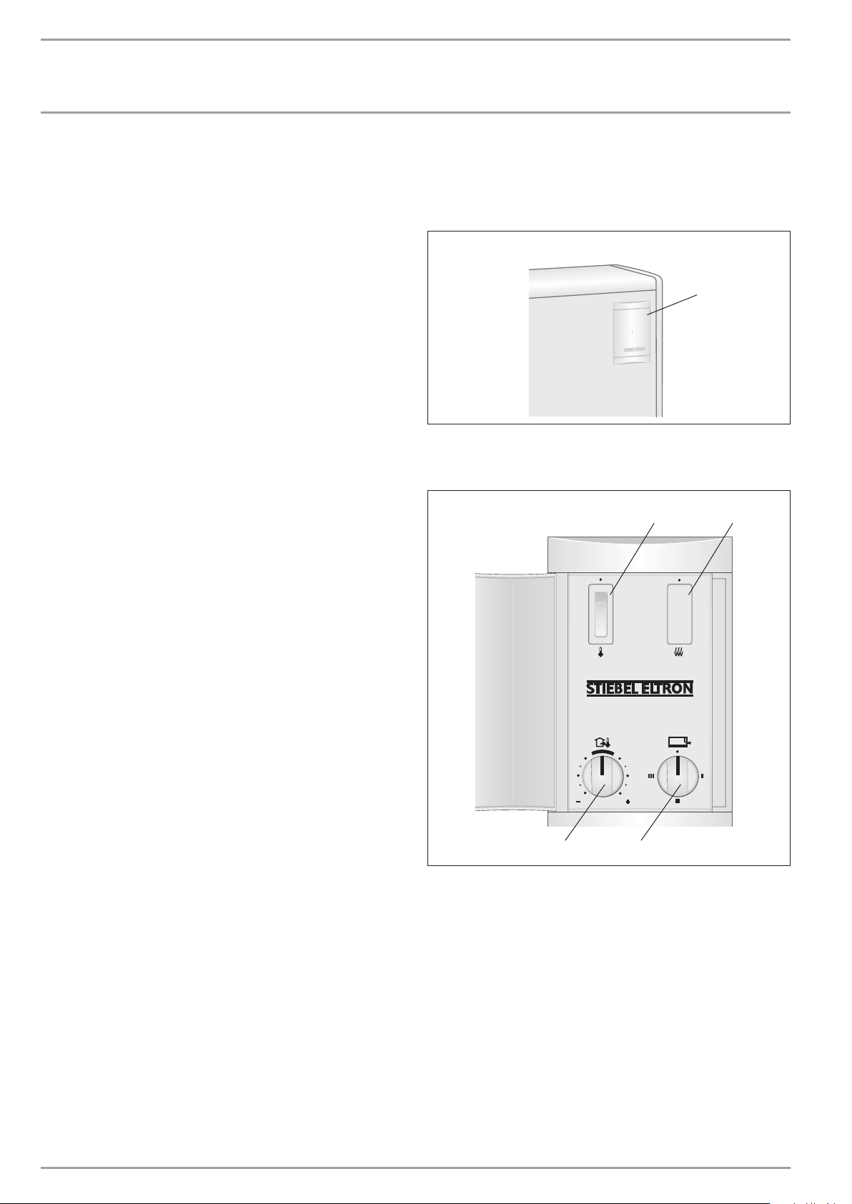
4.1 User interface
To operate, flip open the user interface cover on the front panel.
User interface cover
1
1 User interface
4.2 User interface fascia
User interface
1
2
C26�07�27� 0354
4
1 ON/OFF switch for the discharge controller (special
accessory)
2 ON/OFF switch for a booster heater (special accessory)
3 Charge controller (heat store) – infinitely variable rotary
selector
4 Discharge controller (heat transfer) – infinitely variable
rotary selector for adjusting the room temperature (special
accessory)
26 |ETW 120, 180, 240, 300, 360, 420, 480 electronic www.stiebel-eltron.com
3
C26�07�27� 0326
OPERATION
CLEANING, CARE AND MAINTENANCE
4.3 Factory settings
4.3.1 Heat store
The degree of heat storage (charge) is set via the charge controller
(adjustable with rotary selector 3). For this, a difference must
be made between the operation of appliances with or without
a central, weather-compensated charge control system. The
weather-compensated charge control system is located in the
control panel.
If a central, weather-compensated charge control system is not
installed, set the charge controller as follows:
Setting to stage 1 corresponds to approx. 1/3 of full charging
(spring/autumn).
Setting to stage 2 corresponds to approx. 2/3 of full charging (mild
winter days).
Setting to stage 3 corresponds to full charging (winter days).
Setting to stage 0 corresponds to no charging.
Once you have familiarised yourself with the appliance, you will
be able to find the correct setting as appropriate.
If a central, weather-compensated charge control system is
installed, set the charge controller to stage 3. The weathercompensated charge control system then provides the correct
charge. For differentiated control of individual appliances, you can
also manually match the charge volume to the charge controller,
if a charge control system is installed.
5. Cleaning, care and maintenance
If a pale brownish discolouration appears on the appliance casing,
wipe this off as soo n as possible with a damp cloth and hot soapy water.
Clean the appliance when cold with ordinary cleaning products.
Avoid abrasive or corrosive cleaning products. Never spray
cleaning product into the air slot.
5.1 Cleaning the fluff filter
Important information
Clean the fluff filter in the air inlet grille regularly. This
will ensure trouble-free discharging of the appliance.
If a fluff filter is added, switch OFF the fan.
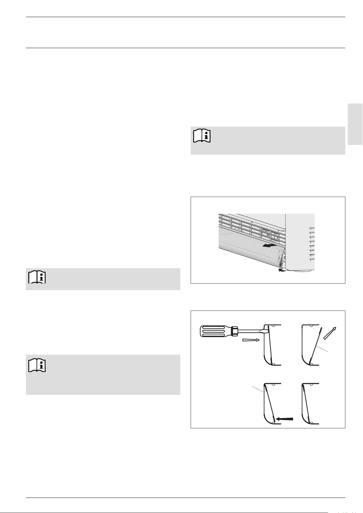
To clean the fluff filter, proceed as follows:
»Remove the air inlet grille from the catch springs by pulling
forwards at the bottom, and release it from the upper locking
device by lifting slightly.
Removing the air inlet grille
ENGLISH
Please read carefully.
Observe the instructions of the charge control system
or group control unit.
4.3.2 Heat transfer
The heat transfer (discharge) is regulated via a room thermostat,
either mounted on the wall or integrated inside the appliance. This
is available from Stiebel Eltron as a special accessory.
Set the required room temperature at the room thermostat, which
then automatically regulates the heat transfer via the fan, so the
set room temperature is constantly maintained.
Please read carefully.
If you will be away for several days during a very cold
period, we recommend leaving the room thermostat
switched on, to maintain a room temperature of e.g.
10 °C, so the building or room does not cool down
(frost protection).
C26�07�27� 0338
»Push the fluff filter out of the grille, e.g. with a screwdriver, and
clean it with a brush, vacuum cleaner or similar.
Removing and refitting the fluff filter
2
1
C26�07�27� 0339
1 Air inlet grille
2 Fluff filter
»Replace the fluff filter in the grille and click into place over
the studs.
www.stiebel-eltron.com ETW 120, 180, 240, 300, 360, 420, 480 electronic | 27
OPERATION
WHAT TO DO IF...
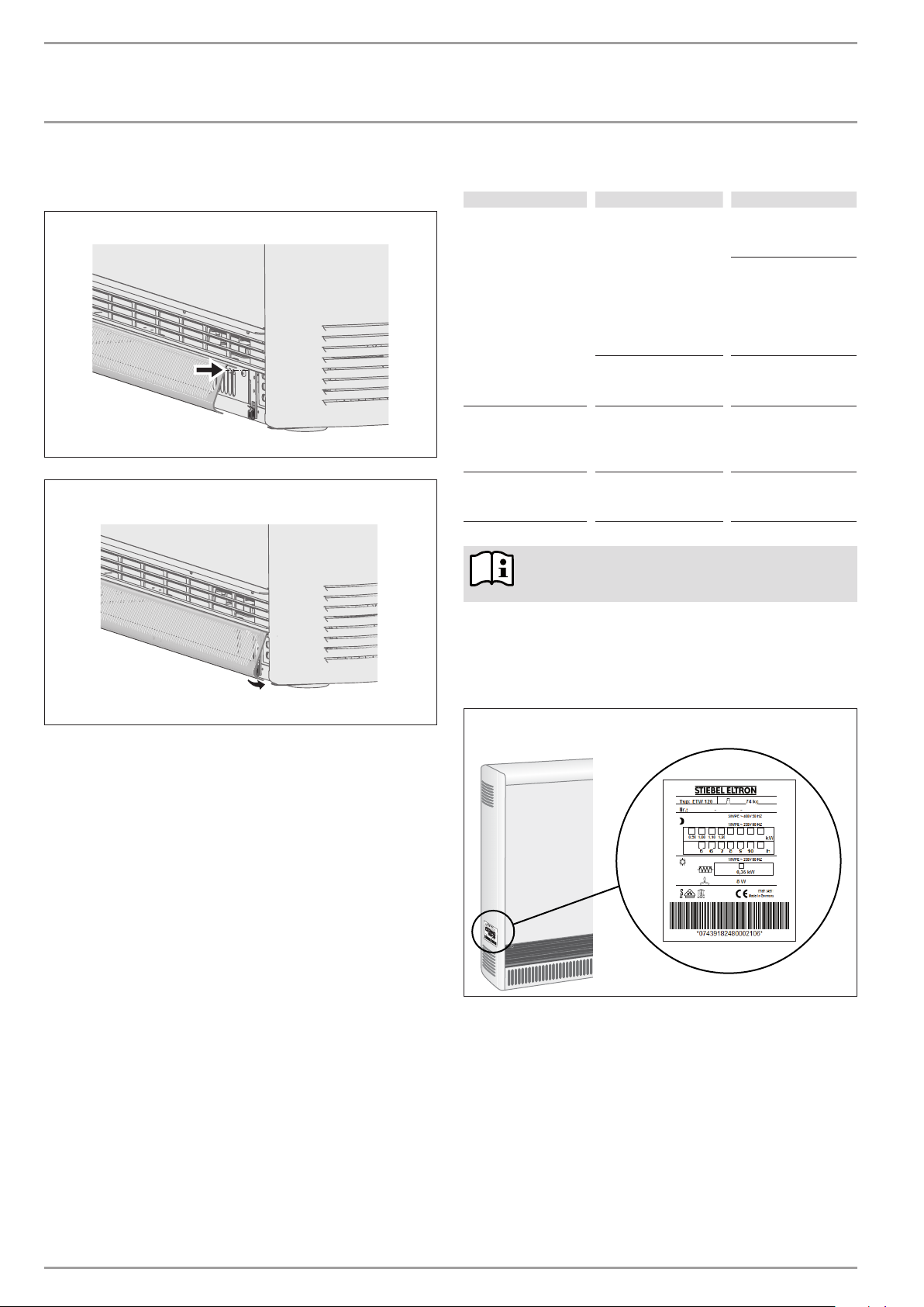
»Hook the upper edge of the air inlet grille into the locking device
screws, and press from below over the catch springs.
Hooking in the air inlet grille
Pressing the catch springs
6. What to do if...
Fault Cause Remedy
The appliance does not
warm up.
The heat transfer of the
appliance is too high
C26�07�27� 0340
even in mild weather.
Appliance does not
discharge.
Note
Changes or removal of faults at the charge control
system only become apparent after renewed charging.
The charge was not set
or was set too low.
No power supply.
The setting at the
charge control system
and/or charge controller
is incorrect.
Fluff filter clogged.
»Set the rotary selector
for the charge
controller higher.
»Set the charge of
the charge control
system higher (see
charge control
system operating
instructions).
»Check the MCB/fuse
and RCD in your
fuse box.
»Adjust the settings.
»See chapter
"Cleaning, care and
maintenance."
If you cannot remedy the fault, contact your contractor. To speed
your call for assistance, provide the number on the type plate (no.
XXXXXX-XXXX-XXXXXX):
C26�07�27� 0341
Type plate example
000000 0000 000000
000000 0000 000000
C26�07�27� 0324
28 |ETW 120, 180, 240, 300, 360, 420, 480 electronic www.stiebel-eltron.com
INSTALLATION
!
!
SAFETY
7. Safety
7.1 Country-specific safety information
All required steps to complete commissioning must be carried out
by a qualified contractor. During this process, these installation
instructions must be observed.
We guarantee trouble-free function and operational reliability
only if the original accessories and spare parts intended for the
appliance are used.
7.2 Instructions, standards and regulations
Risk of damage.
Observe the type plate. The specified voltage must
!
match the mains voltage.
Size the equipment according to the rated consumption
of the appliances.
Note
Observe the Building and Garage Regulations [or local
regulations].
Danger of electrocution!
All electrical connection and installation work must
be conducted in accordance with VDE regulations
(DINVDE0100) [or local regulations], the rules of your
local power supply utility and relevant national and
local regulations.
been removed by the contractor, by pressing the button in the
centre of the high limit safety cut-out.
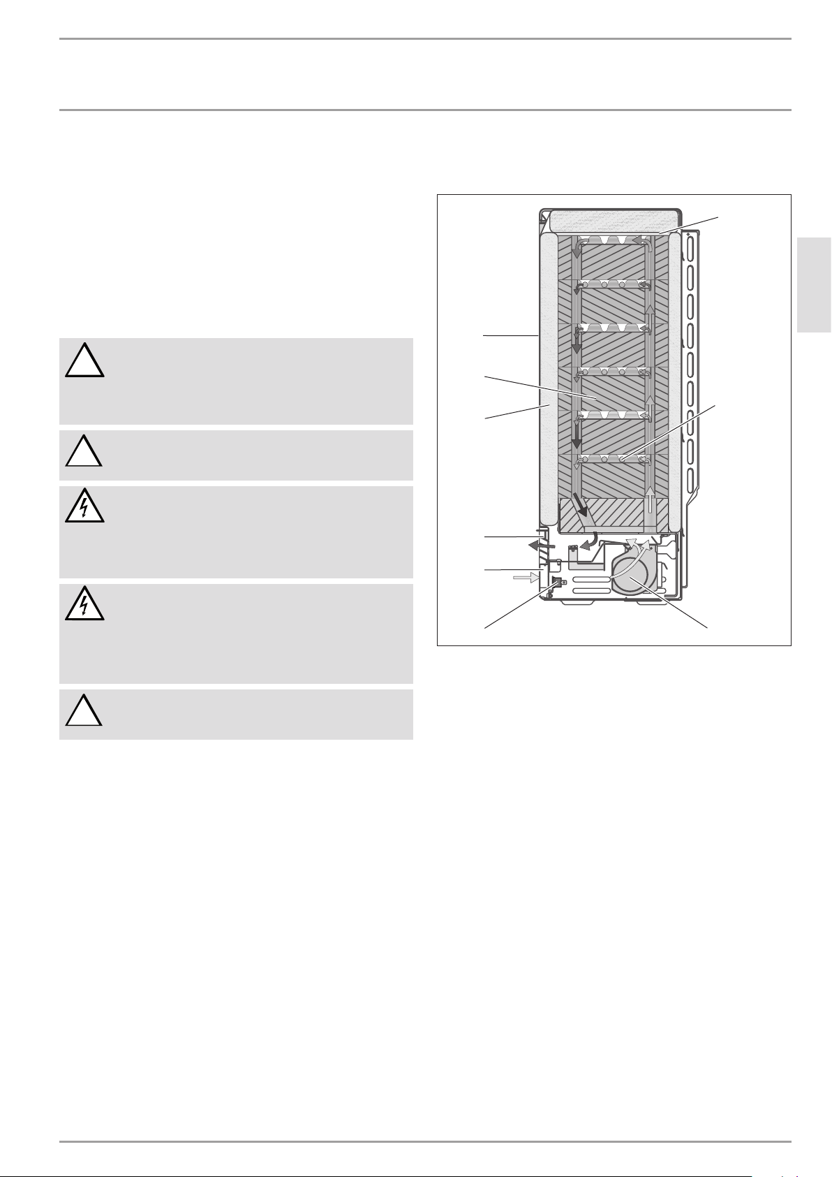
Cutaway
9
8
7
6
5
1
2
ENGLISH
Danger of electrocution!
Connection to the power supply is only possible as a
permanent connection.
The appliance must be able to be separated from the
mains power supply by an isolator that disconnects all
poles with at least 3 mm contact separation.
Important information
Secure the appliance to the wall or floor in such a way
as to ensure stability.
8. Equipment description
8.1 Standard delivery
— Storage heater
— 2-3 wall retainers
— Operating and installation instructions
— Storage blocks
8.2 Factory settings
The appliance connection is wired to the maximum output (100%).
If jumpers at the terminals are moved or removed, the connected
load can be matched.
8.3 Design operation
The storage blocks are heated via the heating elements between
the rows of storage blocks. The charge can be infinitely adjusted
with the charge controller. The start and duration of the charge
time are set by the local power supply utility.
Two integral protective thermostats and a high limit safety
cut-out prevent the appliance overheating. The protective
thermostats switch back on automatically, but the high limit safety
cut-out must be switched back on after the cause of the fault has
4 3
1 Cover panel
2 Heating element
3 Fan (M1)
4 Protective thermostat (N5)
5 Air inlet grille
6 Air outlet grille
7 Insulation
8 Storage blocks
9 Front panel and inner front panel
The stored heat is transferred via a fan, and partially also via the
appliance surface. For this, the room air is drawn in by the fan
through the air inlet grille, and released through the air ducts in
the storage blocks, which heats it. Before the hot air produced in
this way is released via the air outlet grille, it is mixed with cooler
room air via two mixing air dampers, so the expelled air does not
exceed the highest permissible temperature. The position of the
mixing air damper, and thus the mixing ratio of the air, is regulated
via a bi-metal controller.
8.4 Special accessories
— Two-point room temperature controller
— Proportional room temperature controller
— Booster heater
— Rotary selector cap (charge controller)
— Vario panels
— Support panel
C26�07�27� 0328
www.stiebel-eltron.com ETW 120, 180, 240, 300, 360, 420, 480 electronic | 29
 Loading...