

STIEBEL ELTRON ETS 300, ETS 500, ETS 200, ETS 400, ETS 600 Operation And Installation
...
BEDIENUNG UND INSTALLATION
OPERATION AND INSTALLATION
UTILISATION ET INSTALLATION
BEDIENING EN INSTALLATIE
OBSLUHA A INSTALACE
OBSŁUGA I INSTALACJA
Wärmespeicher | Storage heater | Radiateur à accumulation|
Warmtea ccumulator | Akumulační kamna | Zasobniki ciepła
» ETS 200
» ETS 300
» ETS 400
» ETS 500
» ETS 600
» ETS 700 ELECTRONIC

24 | ETS 200-700 www.stiebel-eltron.com
CONTENT | SPECIAL INFORMATION
SPECIAL INFORMATION
OPERATION
1. General information ��������������������������������������� 25
1.1 Safety instructions ���������������������������������������������� 25
1.2 Other symbols in this documentation ���������������������� 25
1.3 Information on the appliance ��������������������������������25
1.4 Units of measurement ����������������������������������������� 25
2. Safety �������������������������������������������������������� 25
2.1 Intended use ����������������������������������������������������� 25
2.2 General safety instructions �����������������������������������26
2.3 Test symbols ����������������������������������������������������� 26
3. Appliance description ������������������������������������� 26
4. Settings ����������������������������������������������������� 26
4.1 User interface ��������������������������������������������������� 26
4.2 User interface ���������������������������������������������������27
4.3 Heat store ��������������������������������������������������������27
4.4 Heat transfer ���������������������������������������������������� 27
5. Cleaning, care and maintenance ������������������������� 27
5.1 Cleaning the fluff filter ����������������������������������������� 28
6. Troubleshooting �������������������������������������������� 28
INSTALLATION
7. Safety �������������������������������������������������������� 29
7.1 General safety instructions ����������������������������������� 29
7.2 Instructions, standards and regulations ������������������� 29
8. Appliance description ������������������������������������� 29
8.1 Mode of operation ���������������������������������������������� 29
8.2 Standard delivery ����������������������������������������������� 30
8.3 Further accessories���������������������������������������������30
9. Preparations ������������������������������������������������ 30
9.1 Installation site �������������������������������������������������� 30
9.2 Minimum clearances ������������������������������������������� 30
10. Installation �������������������������������������������������� 30
10.1 Opening the appliance ����������������������������������������� 30
10.2 Adjusting the charge controller ������������������������������ 31
10.3 Power supply/connecting cables ���������������������������� 32
10.4 Installation versions �������������������������������������������� 32
10.5 Inserting storage blocks ��������������������������������������� 33
10.6 Cleaning the appliance ���������������������������������������� 34
10.7 Power supply ���������������������������������������������������� 34
10.8 Closing the unit ������������������������������������������������� 35
11. Commissioning ��������������������������������������������� 36
11.1 Checks before commissioning��������������������������������36
11.2 Initial start-up ��������������������������������������������������� 36
12. Recommissioning ������������������������������������������ 36
13. Handover ���������������������������������������������������� 36
14. Troubleshooting �������������������������������������������� 37
14.1 Status display of the charge controller ��������������������� 37
14.2 Fault table �������������������������������������������������������� 37
14.3 Symbols on the type plate ������������������������������������38
15. Maintenance ������������������������������������������������ 38
16. Specification ������������������������������������������������ 39
16.1 Dimensions and connections ��������������������������������� 39
16.2 Wiring diagram ������������������������������������������������� 40
16.3 Connection diagrams ������������������������������������������ 41
16.4 Reducing the connected load �������������������������������� 42
16.5 Output matching (rated charge duration) ������������������42
16.6 Data table �������������������������������������������������������� 43
GUARANTEE
ENVIRONMENT AND RECYCLING
SPECIAL INFORMATION
- Keep children under the age of3 away from
the appliance if constant supervision cannot be
guaranteed.
- Children from the age of 3 to 7 may switch the
appliance on and off, provided they are supervised or have been instructed in the safe operation of the appliance and understand any risks
that may result. This is subject to the appliance
having been installed as described. Children from
the age of 3 to 7 must not plug the power cable
into its socket nor regulate the appliance.
- The appliance may be used by children aged8
and older and persons with reduced physical,
sensory or mental capabilities or a lack of experience and know-how, provided that they are supervised or they have been instructed on how to
use the appliance safely and have understood the
resulting risks.
- Children must never play with the appliance. Children must never clean the appliance or perform
user maintenance unless they are supervised.
- Parts of the appliance can get very hot and may
cause burns. Particular caution is advised when
children or vulnerable persons are present.
- Never cover the appliance.
- Never install the appliance directly below a wall
socket.
- Install the appliance in such a way that the control equipment cannot be touched by a person in
the bath or shower.

OPERATION
General information
www.stiebel-eltron.com ETS 200-700 | 25
ENGLISH
- Only use a permanent connection to the power
supply. The appliance must be able to be separated from the power supply by an isolator that
disconnects all poles with at least 3mm contact
separation.
- The power cable may only be replaced (for example if damaged) by a qualified contractor authorised by the manufacturer, using an original spare
part.
- Secure the appliance as described in chapter "Installation/ Installation".
OPERATION
1. General information
The chapters "Special Information" and "Operation" are intended
for both the user and qualified contractors.
The chapter "Installation" is intended for qualified contractors.
Note
Read these instructions carefully before using the appliance and retain them for future reference.
Pass on the instructions to a new user if required.
1.1 Safety instructions
1.1.1 Structure of safety instructions
KEYWORD Type of risk
Here, possible consequences are listed that may result
from failure to observe the safety instructions.
Steps to prevent the risk are listed.
1.1.2 Symbols, type of risk
Symbol Type of risk
Injury
Electrocution
Burns
(burns, scalding)
1.1.3 Keywords
KEYWORD Meaning
DANGER Failure to observe this information will result in serious
injury or death.
WARNING Failure to observe this information may result in serious
injury or death.
CAUTION Failure to observe this information may result in non-seri-
ous or minor injury.
1.2 Other symbols in this documentation
Note
General information is identified by the adjacent symbol.
Read these texts carefully.
Symbol Meaning
Material losses
(appliance damage, consequential losses and environmental pollution)
Appliance disposal
This symbol indicates that you have to do something. The ac-
tion you need to take is described step by step.
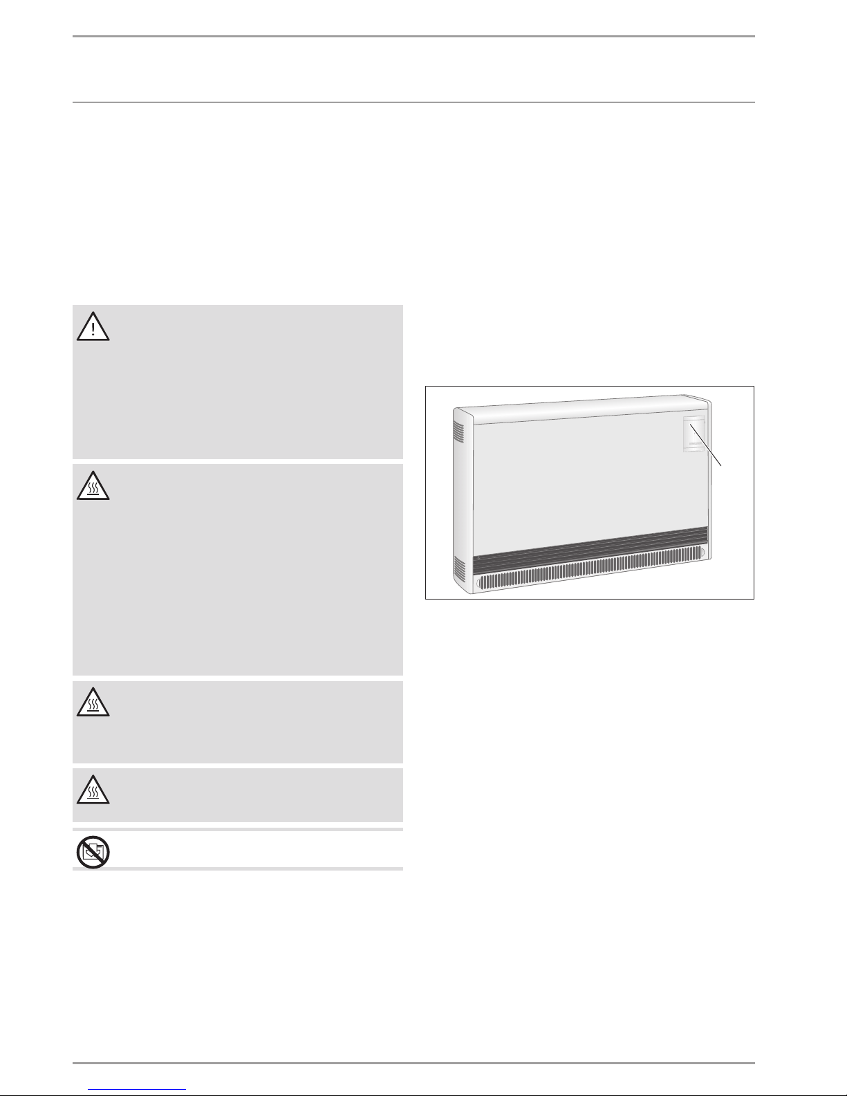
1.3 Information on the appliance
Symbol Meaning
Never cover the appliance
1.4 Units of measurement
Note
All measurements are given in mm unless stated otherwise.
2. Safety
2.1 Intended use
This appliance is designed to heat living areas.
This appliance is intended for domestic use. It can be used safely
by untrained persons. The appliance can also be used in a non-domestic environment, e.g.in a small business, as long as it is used
in the same way.
Any other use beyond that described shall be deemed inappropriate. Observation of these instructions and of instructions for any
accessories used is also part of the correct use of this appliance.
OPERATION
Appliance description
26 | ETS 200-700 www.stiebel-eltron.com
2.2 General safety instructions
Observe the following safety instructions and regulations.
- The electrical installation and installation of the appliance
must only be carried out by a qualified contractor or by our
customer service engineers.
- The qualified contractor is responsible for adherence to
all currently applicable regulations during installation and
commissioning.
- Operate the appliance only when fully installed and with all
safety equipment fitted.
WARNING Injury
The appliance may be used by children aged 8 and older
and persons with reduced physical, sensory or mental
capabilities or a lack of experience and know-how, provided that they are supervised or they have been instructed on how to use the appliance safely and have
understood the resulting risks. Children must never play
with the appliance. Children must never clean the appliance or perform user maintenance unless they are
supervised.
WARNING Burns
Never operate this appliance
- in rooms where the appliance is at risk from fire or
explosion as a result of chemicals, dust, gases or
vapours.
- in the direct proximity of pipes or receptacles that
carry or contain flammable or explosive materials.
- if work such as laying tiles, sanding or sealing is
being carried out in the installation room.
- if naphtha, sprays, floor polish or similar products
are handled. Ventilate the room sufficiently before
heating.
- if the minimum clearances to adjacent surfaces are
not maintained.
WARNING Burns
Never place any flammable, combustible or insulating
objects or materials, such as laundry, blankets, magazines, containers with floor polish or naphtha, spray cans
or similar on the appliance or in direct proximity to it.
CAUTION Burns
The surfaces of the appliance casing and the expelled air
become hot during operation (above 80 °C).
CAUTION Overheating
Never cover the appliance.
2.3 Test symbols
See type plate on the appliance.
3. Appliance description
Electrically generated heat is stored with this appliance. The electrical heat is generated when the power supply utility enables the
supply of cheaper off-peak power.
The times when this supply is enabled depend on the relevant
power supply utility. The times when it is enabled are predominantly at night.
Subject to the required room temperature, the stored heat is
transferred to the room as hot air via a fan, and partially via the
appliance surface.
4. Settings
4.1 User interface
26� 07�27�035 4�
1
1 User interface
To operate, flip open the user interface cover.
OPERATION
Cleaning, care and maintenance
www.stiebel-eltron.com ETS 200-700 | 27
ENGLISH
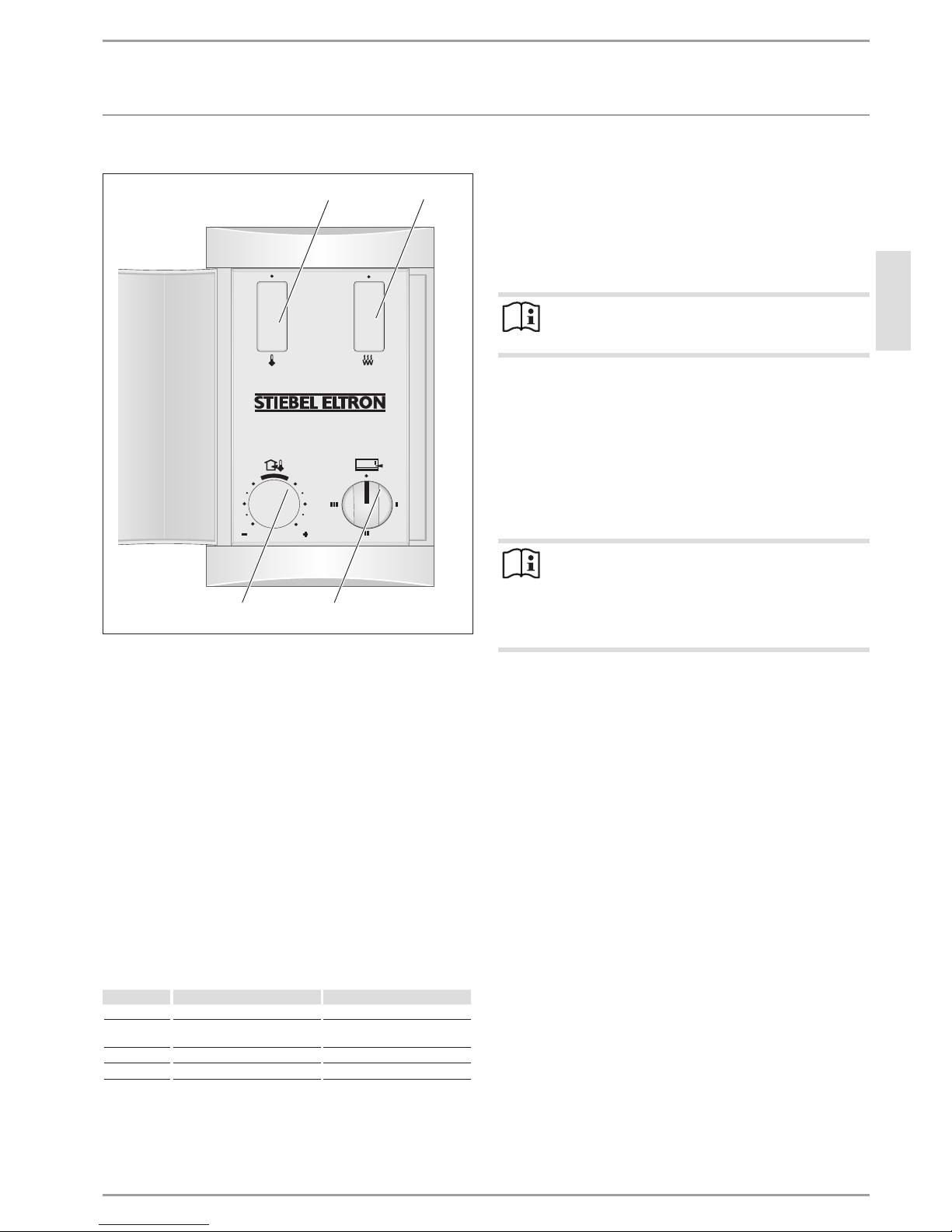
4.2 User interface
26� 07�27�041 1�
1
2
4 3
1 ON/OFF switch for the discharge controller (accessory)
2 ON/OFF switch for a booster heater (accessory)
3 “Charge control” rotary selector (heat storage),
variable adjustment
4 “Discharge controller” rotary selector (heat transfer),
variable adjustment of the room temperature (accessory)
4.3 Heat store
The degree of heat storage (charge) is set via the charge controller.
The settings you have to make via the charge controller depend
on whether you use an appliance with or without a central weather-compensated charge control system.
The weather-compensated charge control system is located in
the control panel.
4.3.1 Appliances without a weather-compensated charge
control system
Adjust the “charge controller” rotary selector according to
the following information.
Stage Charge level Suitable for
Stage 0 No charge Stage 1 Approx. 1/3 of full charge Between seasons
(spring/autumn)
Stage 2 Approx. 2/3 of full charge Mild winter days
Stage 3 Full charge Winter days
Once you have familiarised yourself with the appliance, you will
be able to find the correct setting as appropriate.
4.3.2 Appliances with a weather-compensated charge control
system
Set the “charge control” rotary selector to stage 3.
The weather-compensated charge control system ensures the
correct charge level.
For differentiated control of individual appliances, you can also
manually match the charge volume via the charge controller.
Note
Observe the instructions of the charge control system or
group control unit.
4.4 Heat transfer
The heat transfer (discharge) is regulated via a room temperature controller, either mounted on the wall or integrated inside
the appliance. We supply the room temperature controller as an
accessory.
The room temperature controller automatically controls the heat
transfer via the fan so that the adjusted room temperature is kept
constant.
Note
On extremely cold days, it is advisable not to switch off
the room temperature controller when you are away for
several days, but to set a reduced room temperature e.g.
10°C. This setting prevents the room temperature from
falling too low (frost protection).
5. Cleaning, care and maintenance
If a pale brownish discolouration appears on the appliance casing,
wipe this off as soon as possible with a damp cloth and hot water
with washing-up liquid.
Clean the appliance when cold with ordinary cleaning
products.
Avoid abrasive or corrosive cleaning products. Never spray
cleaning spray into the air slot.
OPERATION
Troubleshooting
28 | ETS 200-700 www.stiebel-eltron.com
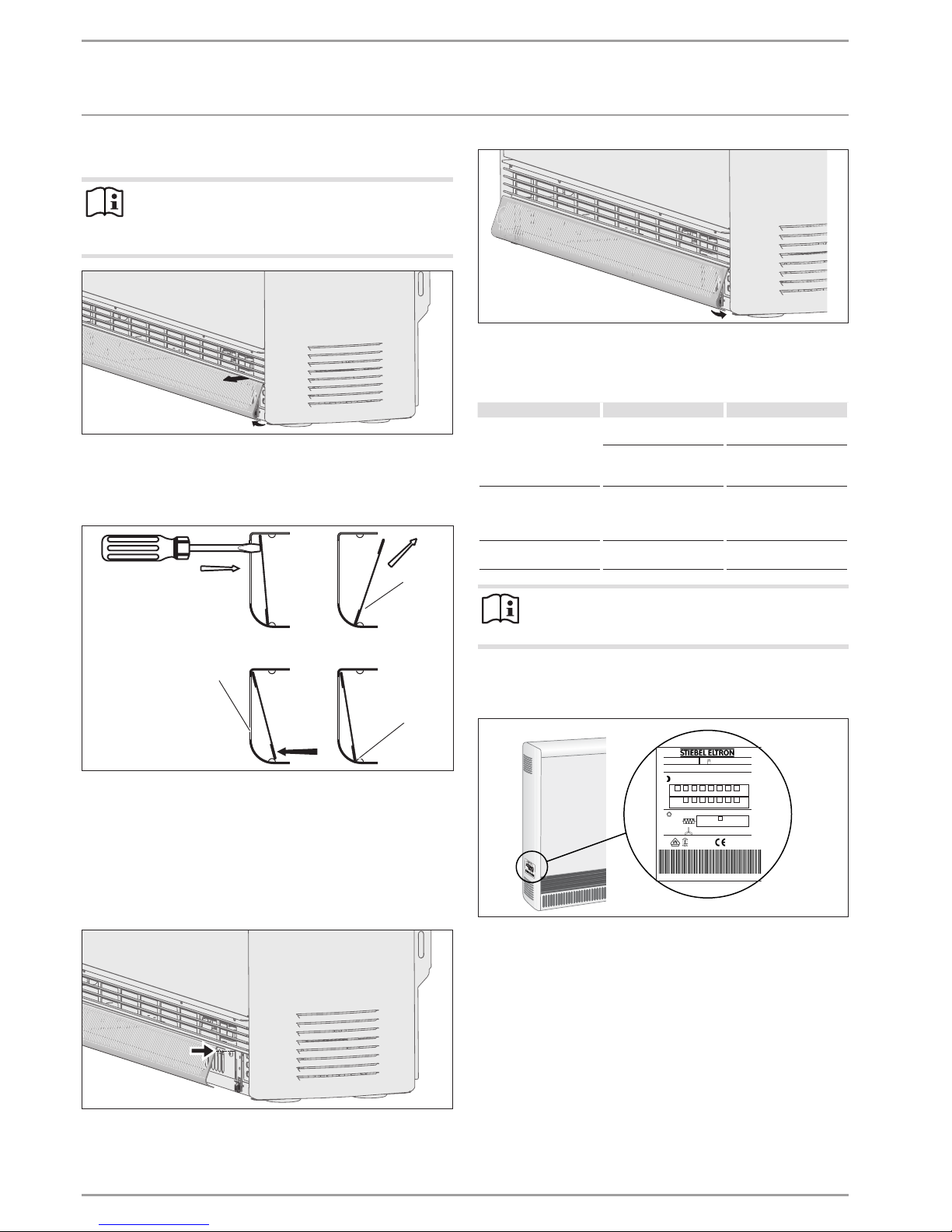
5.1 Cleaning the fluff filter
Note
Clean the fluff filter in the air inlet grille regularly. This
will ensure trouble-free discharging of the appliance. If
a fluff filter is added, switch OFF the fan.
26� 07�27�033 8
Remove the air inlet grille from the catch springs by pulling it
forwards at the bottom.
Release the air inlet grille by pulling it out of the upper lock-
ing mechanism.
26� 07�27�0339�
3
1
2
1 Fluff filter
2 Air inlet grille
3 Studs
Press the fluff filter out of the grille. Use, for example, a
screwdriver for this.
Clean the fluff filter with a brush or a vacuum cleaner.
Replace the fluff filter in the grille and click into place over
the studs.
26� 07�27�0340
Hook the upper edge of the air inlet grille on to the locking
screws.
26� 07�27�0341
Press in the air inlet grille over the catch springs.
6. Troubleshooting
Problem Cause
Remedy
The appliance does not
heat up.
The charge was not set or
was set too low.
Set the "charge control"
rotary selector higher.
No power supply.
Check the fuse/MCB and
the RCD in the domestic
distribution board.
The heat transfer of the
appliance is too high
even in mild weather.
The setting at the charge
control system and/or
charge controller is incorrect.
Adjust the settings.
Appliance does not discharge.
The fluff filter is clogged. See chapter "Cleaning,
care and maintenance".
Note
Changes or removal of faults at the charge control system
only become apparent after renewed charging.
If you cannot remedy the fault, notify your qualified contractor.
To facilitate and speed up your enquiry, please provide the serial
number from the type plate (000000-0000-000000).
000000 0000 000000
26� 07�27�0324�
ETS 700
Nr.: 074489 - 8252 - 000194
Typ: 373 kg
Made in Germany
26 W
kW
h5 6 7 8 9 10
5,83
6,42
7,00
6,75
7,50 8,24
9,00
3/N/PE ~ 400V 50 HZ
1/N/PE ~ 230V 50 HZ
171671 -34511
1,5 kW
5,25
*0744898252000194K*
INSTALLATION
Safety
www.stiebel-eltron.com ETS 200-700 | 29
ENGLISH
INSTALLATION
7. Safety
Only a qualified contractor should carry out installation, commissioning, maintenance and repair of the appliance.
7.1 General safety instructions
We guarantee trouble-free function and operational reliability only
if original accessories and spare parts intended for the appliance
are used.
7.2 Instructions, standards and regulations
WARNING Electrocution
Carry out all electrical connection and installation work
in accordance with relevant regulations.
WARNING Electrocution
Only use a permanent connection to the power supply.
The appliance must be able to be separated from the
power supply by an isolator that disconnects all poles
with at least 3mm contact separation.
Material losses
Observe the type plate. The specified voltage must match
the mains voltage.
Size the equipment according to the rated consumption
of the appliances.
Material losses
Secure the appliance to the wall or floor in such a way
as to ensure stability.
Material losses
Observe all applicable national and regional regulations
and instructions.
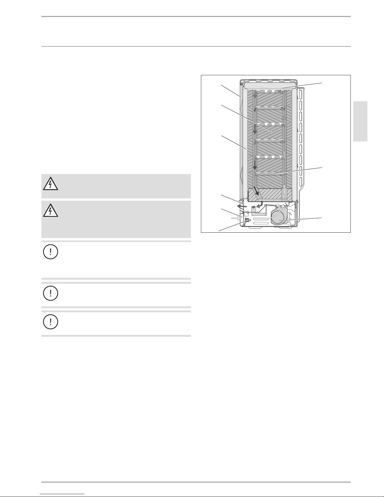
8. Appliance description
9
8
7
6
5
4
1
2
3
26� 07�27�0022�
1 Cover panel
2 Heating element
3 Fan (M1)
4 Protective temperature controller (N5)
5 Air inlet grille
6 Air outlet grille
7 Thermal insulation
8 Storage blocks
9 Front panel and inner front panel
8.1 Mode of operation
The storage blocks are heated via the heating elements between
the rows of storage blocks. The charge can be infinitely adjusted
with the charge controller. The start and duration of the charge
time are set by the local power supply utility.
Two integral protective temperature controllers and a high limit
safety cut-out prevent the appliance overheating. The protective
temperature controllers switch back on automatically, but the high
limit safety cut-out must be switched back on by pressing the
button in the centre of the high limit safety cut-out after the cause
of the fault has been removed.
The stored heat is transferred via a fan, and partially also via the
appliance surface. For this, the room air is drawn in by the fan
through the air inlet grille, and released through the air ducts in
the storage blocks, which heat it.
Before the hot air produced in this way is released via the air
outlet grille, it is mixed with cooler indoor air via two mixing air
dampers, so the expelled air does not exceed the highest permissible temperature. The position of the mixing air damper, and thus
the mixing ratio of the air, is regulated via a bi-metal controller.
 Loading...