

STIEBEL ELTRON DHB-E 11 SLi electronic, DHB-E 13 SLi electronic, DHB-E 18 SLi 25 A electronic, DHB-E 18/21/24 SLi electronic, DHB-E 27 SLi electronic Operation And Installation
BEDIENUNG UND INSTALLATION
OPERATING AND INSTALLATION
UTILISATION ET INSTALLATION
GEBRUIK EN INSTALLATIE
OBSŁUGA I INSTALACJA
OBSLUHA A INSTALACE
Elektronisch geregelter Durchlauferhitzer | Electronically controlled instantaneous
water heater | Chauffe-eau instantanés à régulation électronique | Elektronisch
geregelde doorstromer | Elektronicznie regulowany przepływowy ogrzewacz wody |
Elektronicky regulovaný průtokový ohřívač
» DHB-E 11 SLi electronic
» DHB-E 13 SLi electronic
» DHB-E 18 SLi 25 A electronic
» DHB-E 18/21/24 SLi electronic
» DHB-E 27 SLi electronic
electronic
°C
45
50
40
55
35
60
30

CONTENTS
SPECIAL INFORMATION
OPERATION
1. General information ��������������������������������������� 20
1.1 Safety instructions ���������������������������������������������� 20
1.2 Other symbols in this documentation ���������������������� 20
1.3 Units of measurement ����������������������������������������� 21
2. Safety �������������������������������������������������������� 21
2.1 Intended use ����������������������������������������������������� 21
2.2 General safety instructions �����������������������������������21
2.3 Test symbols ����������������������������������������������������� 21
3. Appliance description ������������������������������������� 21
4. Operation ��������������������������������������������������� 21
4.1 Recommended settings ��������������������������������������� 22
4.2 Temperature limit / Anti-scalding protection ������������� 22
5. Cleaning, care and maintenance ������������������������� 22
6. Troubleshooting �������������������������������������������� 22
INSTALLATION
7. Safety �������������������������������������������������������� 23
7.1 General safety instructions ����������������������������������� 23
7.2 Instructions, standards and regulations ������������������� 23
8. Appliance description ������������������������������������� 23
8.1 Standard delivery ����������������������������������������������� 23
8.2 Accessories ������������������������������������������������������� 23
9. Preparations ������������������������������������������������ 24
9.1 Installation site �������������������������������������������������� 24
9.2 Water installation ����������������������������������������������� 24
9.3 Appliance with adjustable connected load ���������������� 25
10. Installation �������������������������������������������������� 25
10.1 Standard installation ������������������������������������������� 25
10.2 Completing the installation ����������������������������������� 27
11. Commissioning ��������������������������������������������� 27
11.1 Initial start-up ��������������������������������������������������� 27
11.2 Recommissioning ����������������������������������������������� 28
12. Shutdown ��������������������������������������������������� 28
13. Installation options ���������������������������������������� 28
13.1 Electrical connection from above on unfinished walls �� 28
13.2 Electrical connection on finished walls �������������������� 28
13.3 Large conductor cross-section for electrical
connection from below ���������������������������������������� 28
13.4 Connecting a load shedding relay ��������������������������� 29
13.5 Water installation on finished walls ������������������������29
13.6 Water installation on finished walls with solder/
compression fitting ��������������������������������������������� 29
13.7 Water installation on finished walls; fitting the
appliance cover �������������������������������������������������29
13.8 Fitting the base part of the back panel with threaded
fittings on finished walls �������������������������������������� 29
13.9 Wall mounting bracket when replacing an appliance ��� 30
13.10 Installation with offset tiles ����������������������������������� 30
13.11 Pivoting appliance cover ��������������������������������������30
13.12 Temperature limit / Anti-scalding protection ������������� 30
14. Troubleshooting �������������������������������������������� 31
15. Maintenance ������������������������������������������������ 32
16. Specification ������������������������������������������������ 32
16.1 Dimensions and connections ��������������������������������� 32
16.2 Wiring diagram ������������������������������������������������� 32
16.3 DHW output ������������������������������������������������������ 33
16.4 Application areas/ conversion table ����������������������� 33
16.5 Pressure drop ��������������������������������������������������� 33
16.6 Details on energy consumption ������������������������������ 33
16.7 Data table ��������������������������������������������������������34
GUARANTEE
ENVIRONMENT AND RECYCLING
ENGLISH
www.stiebel-eltron.com DHB-E SLi | 19
SPECIAL INFORMATION
SPECIAL INFORMATION | OPERATION
General information
General information
SPECIAL INFORMATION
- The appliance may be used by children aged 3
and older and persons with reduced physical,
sensory or mental capabilities or a lack of experience and know-how, provided that they are
supervised or they have been instructed on how
to use the appliance safely and have understood
the resulting risks. Children must never play with
the appliance. Children must never clean the appliance or perform user maintenance unless they
are supervised.
- The tap can reach temperatures in excess of
60°C. There is a risk of scalding at outlet temperatures in excess of 43 °C.
- Ensure the appliance can be separated from the
power supply by an isolator that disconnects all
poles with at least 3mm contact separation.
- The specified voltage must match the mains
voltage.
- The appliance must be connected to earth.
- The appliance must be permanently connected to
fixed wiring.
- Secure the appliance as described in chapter “Installation/ Installation”.
- Observe the maximum permissible pressure (see
chapter “Installation/ Specification/ Data table”).
OPERATION
1. General information
The chapters “Special Information” and “Operation” are intended
for both the user and qualified contractors.
The chapter “Installation” is intended for qualified contractors.
Note
Read these instructions carefully before using the appliance and retain them for future reference.
Pass on the instructions to a new user if required.
1.1 Safety instructions
1.1.1 Structure of safety instructions
KEYWORD Type of risk
!
Here, possible consequences are listed that may result
from failure to observe the safety instructions.
Steps to prevent the risk are listed.
1.1.2 Symbols, type of risk
Symbol Type of risk
!
Injury
Electrocution
Burns
(burns, scalding)
- The specific water resistivity of the mains water
supply must not be undershot (see chapter “Installation / Specification / Data table”).
- Drain the appliance as described in chapter “Installation/ Maintenance/ Draining the
appliance”.
1.1.3 Keywords
KEYWORD Meaning
DANGER Failure to observe this information will result in serious
injury or death.
WARNING Failure to observe this information may result in serious
injury or death.
CAUTION Failure to observe this information may result in non-seri-
ous or minor injury.
1.2 Other symbols in this documentation
Note
General information is identified by the adjacent symbol.
Read these texts carefully.
20 | DHB-E SLi www.stiebel-eltron.com
OPERATION
45
Safety
Symbol Meaning
!
This symbol indicates that you have to do something. The ac-
tion you need to take is described step by step.
Material losses
(appliance damage, consequential losses and environmental pollution)
Appliance disposal
1.3 Units of measurement
Note
All measurements are given in mm unless stated otherwise.
2. Safety
2.1 Intended use
This appliance is intended for heating domestic hot water (DHW)
or for reheating preheated water and can supply one or several
draw-off points.
This appliance is intended for domestic use. It can be used safely
by untrained persons. The appliance can also be used in a non-domestic environment, e.g. in a small business, as long as it is used
in the same way.
Any other use beyond that described shall be deemed inappropriate. Observation of these instructions and of instructions for any
accessories used is also part of the correct use of this appliance.
2.2 General safety instructions
CAUTION Burns
During operation, the tap can reach temperatures in excess of 60 °C.
There is a risk of scalding at outlet temperatures in excess of 43°C.
2.3 Test symbols
See type plate on the appliance.
3. Appliance description
The electronically controlled instantaneous water heater maintains a constant outlet temperature up to its output limit, irrespective of the inlet temperature.
The appliance heats the water directly at the draw-off point, as
soon as you turn on the hot water tap. The short pipe runs ensure
that energy and water losses are minimal.
For the start flow rate, see chapter “Installation/ Specification/
Data table, On”.
The DHW output depends on the cold water temperature, the
heating output, the flow rate and the selected set temperature.
Water will not be reheated if the maximum inlet temperature for
reheating is exceeded.
DHW temperature
The DHW outlet temperature can be variably adjusted.
Temperature limit / Anti-scalding protection
The maximum outlet temperature for the appliance can be limited
to 43°C. For this, contact your local heating contractor.
Heating system
The bare wire heating system has a pressure-tested plastic casing.
The heating system is suitable for (both) soft and hard water and
is largely resistant to scale build-up. This heating system ensures
rapid and efficient DHW availability.
Note
The appliance is equipped with an air detector that largely prevents damage to the heating system. If, during operation, air is drawn into the appliance, the appliance
shuts down for one minute, thereby protecting the heating system.
ENGLISH
CAUTION Burns
When operating the appliance with preheated water, e.g.
from a solar thermal system, the DHW temperature may
vary from the selected set temperature.
WARNING Injury
!
The appliance may be used by children aged 3 and older
and persons with reduced physical, sensory or mental
capabilities or a lack of experience and know-how, provided that they are supervised or they have been instructed on how to use the appliance safely and have
understood the resulting risks. Children must never play
with the appliance. Children must never clean the appliance or perform user maintenance unless they are
supervised.
Material losses
!
The user should protect the appliance and its tap against
frost.
www.stiebel-eltron.com DHB-E SLi | 21
4. Operation
40
35
30
Turn the temperature selector to the required position.
If the outlet temperature fails to reach the required level with the
tap fully open and the temperature selector set to maximum, then
more water is flowing through the appliance than can be heated
by the heating element.
Reduce the flow rate at the tap.
50
55
60
26�02�02�1381
OPERATION
Cleaning, care and maintenance
4.1 Recommended settings
Thermostatic valve
If the appliance is being operated with a thermostatic valve, we
recommend setting the temperature on the appliance to maximum. The required temperature can then be set at the thermostatic valve.
DHB-E ... SL
Following an interruption to the water supply
Material losses
!
To ensure that the bare wire heating system is not damaged following an interruption to the water supply, the
appliance must be restarted taking the following steps.
Disconnect the appliance from the power supply by
removing the fuses/tripping the MCBs.
Open the tap for one minute until the appliance and
its upstream cold water inlet line are free of air.
Switch the mains power back ON again.
4.2 Temperature limit / Anti-scalding protection
The maximum outlet temperature for the appliance can be limited
to 43°C. For this, contact your local heating contractor.
5. Cleaning, care and maintenance
Never use abrasive or corrosive cleaning agents. A damp
cloth is sufficient for cleaning the appliance.
Check the taps regularly. Limescale deposits at the tap out-
lets can be removed using commercially available descaling
agents.
26�02�02�0818
6. Troubleshooting
Problem Cause Remedy
The appliance will not
start despite the DHW
valve being fully open.
When hot water is being
drawn off, cold water
flows for a short period.
Required temperature
>45°C is not achieved.
Cold water inlet tempera-
If you cannot remedy the fault, notify your qualified contractor.
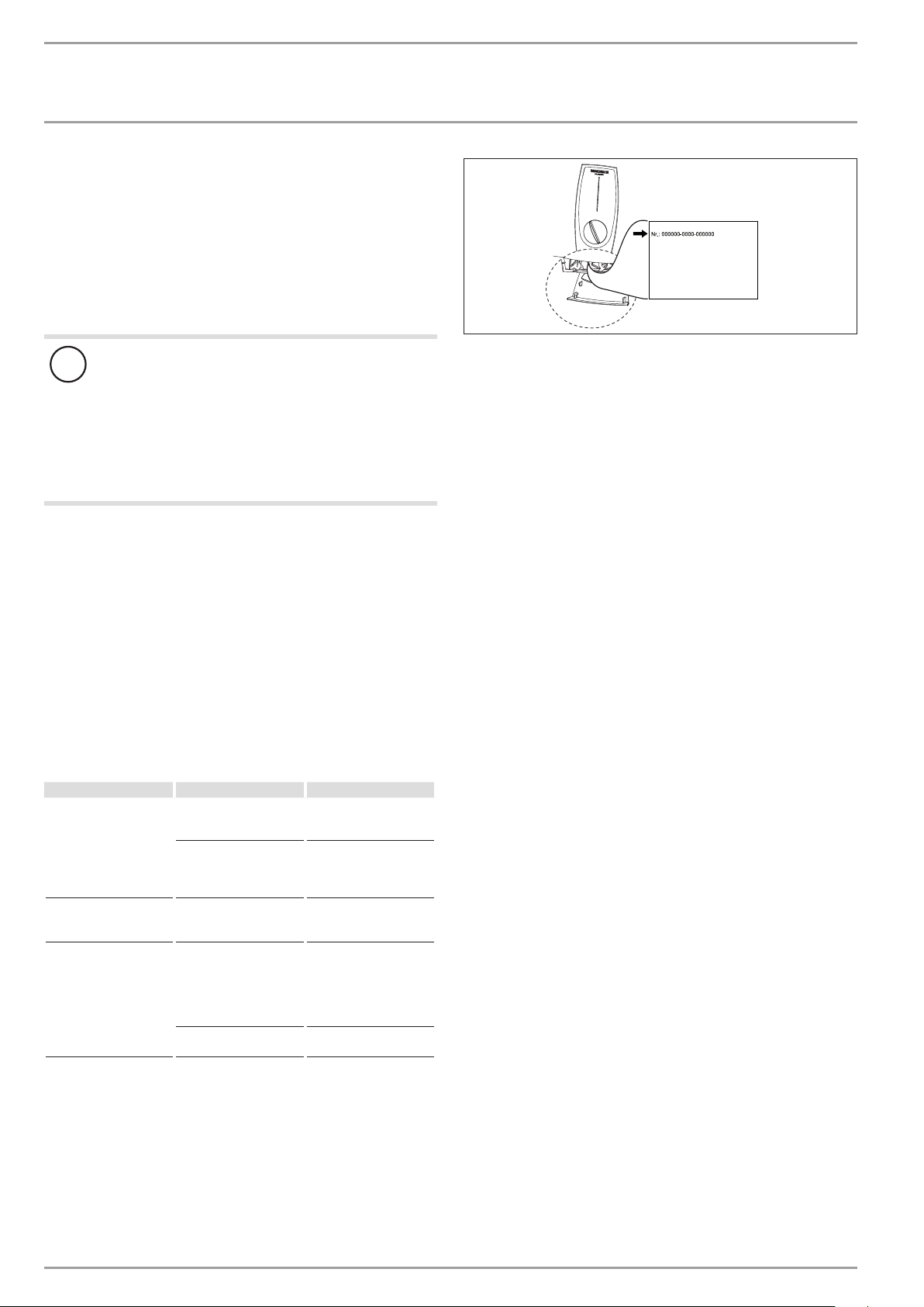
To facilitate and speed up your request, provide the number from
the type plate (000000-0000-000000).
There is no power.
The aerator in the tap
or the shower head is
scaled up or contaminated.
The air sensor detects air
in the water and briefly
switches the heater off.
The water supply has
been interrupted.
ture is >45°C.
Check the fuses/MCBs in
your fuse box/distribution panel.
Clean and/or descale the
aerator or shower head.
The appliance restarts
automatically after
1minute.
Vent the appliance and
the cold water supply line
(see chapter "Operation/
Recommended settings/
Following an interruption
to the water supply").
Reduce the cold water
inlet temperature.
22 | DHB-E SLi www.stiebel-eltron.com
INSTALLAT ION
Safety
INSTALLATION
7. Safety
Only a qualified contractor should carry out installation, commissioning, maintenance and repair of the appliance.
7.1 General safety instructions
We guarantee trouble-free function and operational reliability only
if original accessories and spare parts intended for the appliance
are used.
Material losses
!
Observe the maximum permissible inlet temperature
(see chapter "Installation/ Specification/ Data table").
Higher temperatures may damage the appliance. The
inlet temperature can be limited by means of a central
thermostatic valve (see chapter "Installation/ Appliance
description/ Accessories").
7.2 Instructions, standards and regulations
Note
Observe all applicable national and regional regulations
and instructions.
- The IP 25 (hoseproof) rating can only be ensured with a correctly fitted cable grommet.
- The specific electrical resistance of the water must not fall
below that stated on the type plate. In a linked water network, factor in the lowest electrical resistance of the water
(see chapter “Installation/ Specification/ Data table”). Your
water supply utility will advise you of the specific electrical
resistance or conductivity of the water.
8.2 Accessories
Taps/valves
- MEKD mono lever kitchen pressure tap
- MEBD mono lever bath pressure tap
Plug G½A
If you use pressure taps for finished walls other than those recommended in the accessories, please use the plugs.
ENGLISH
Installation set for finished walls
- Solder fitting - copper pipe for soldered connection Ø12mm
- Compression fitting - copper pipe
- Compression fitting - plastic pipe (suitable for Viega: Sanfix-Plus or Sanfix-Fosta)
Universal mounting frame
- Mounting frame with electrical connections
Pipe assembly for undersink appliances
You will need the undersink installation set if you make the water
connections (G⅜A) at the top of the appliance.
Pipe assembly for offset installation
Use this pipe assembly set if you intend to offset the appliance by
90mm downwards from the water connection.
Pipe assembly for replacing a gas water heater
You will need this pipe assembly set if the existing installation
has gas water heater connections (cold water connection on the
left-hand side, DHW connection on the right-hand side).
Pipe assembly DHB water plug-in couplings
Use the water plug-in couplings if the existing installation contains
water plug-in connections from a DHB water heater.
8. Appliance description
8.1 Standard delivery
The following are delivered with the appliance:
- Wall mounting bracket
- Installation template
- 2 twin connectors
- Cold water 3-way ball shut-off valve
- DHW tee
- Flat gaskets
- Strainer
- Flow limiter
- Plastic profile washer
- Plastic connection pieces/ installation aid
- Cap and back panel guides
www.stiebel-eltron.com DHB-E SLi | 23
Load shedding relay (LR 1-A)
The load shedding relay for installation in the distribution board
provides priority control for the instantaneous water heater when
other appliances, such as electric storage heaters, are being operated simultaneously.
ZTA 3/4 – Central thermostatic valve
Thermostatic valve for central premixing, for example when operating an instantaneous water heater with a solar thermal system.
 Loading...