

Page 1

STIEBEL ELTRON
Technik zum Wohlfühlen
CAES 500/750/1000/1250/1500/1750/2000
FRANÇAIS 3-5
Convecteur électrique mural
Instructions de montage et d'utilisation
CESKY 6-8
Návod k montáži a používání
ENGLISH 9-11
Wall-mounted electric heating convector
Instructions for installation and use
Page 2
Cesky
INSTALACE KONVEKTORU
Umístění konvektoru
Protože se jedná o konvektor el.třídy II s el.krytím IP 24, je
možno jej dle ČSN 33 0300 nainstalovat v prostředí základním
( např.kanceláře, obývací místnosti, koupelny a sprchy). Jeho
použití je povoleno i pro
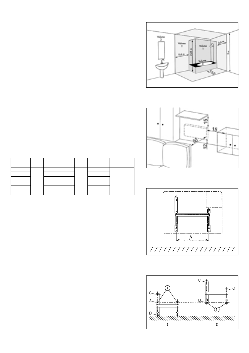
ochrannou vzdálenost v koupelnách
dle ČSN 33 2135 (obr. 1), ovšem za předpokladu, že osoby
používající vanu nebo sprchu, nemohou přijít do styku
s regulačními zařízeními konvektoru.
Dbejte na dodržování doporučených minimálních vzdáleností
na obr. 2.
Nemontujte přístroj v bezprostřední blízkosti pod napevno
instalovanou zásuvkou (popř.rozvodnou krabicí).
Postavte přístroj tak, aby byl chráněn před vzdušnými proudy,
které by mohly narušit jeho regulaci.
Montáž stěnového držáku
Pozor ! (Obr.3-4)
Obr.1
VýkonKWEp incmDélka přistrojecmhtmmRozteč AcmRosteč B, C
0,5/0,75 36,9 12,10
1 44,35 19,50
1,25 51,75 26,90
100
1,5 59,15 34,30
1,75 66,55 41,70
2
73,95
45
49,10
cm
B = 25,6
C = 15,8
Obr. 4.I.: Postavte stěnový držák na podlahu a označte
na stěně polohu spodních upevňovacích bodů (označení 1),
které odpovídají otvorům A.
Obr. 4.II.: Poté stěnový držák nadzdvihněte a přidržte tak,
aby se oba spodní otvory B kryly s právě označenými body
1. Nyní můžete otvory C v držáku označit oba otvory pro
připevnění na stěnu s označením C a D ( II ). Potom můžete
vyvrtat díry, vsadit hmoždinky a upevnit držák čtyřmi šrouby
v otvorech B, C a D.
Elektrické připojení
Napájení: 230 V 50 Hz
Konvektory dodáváme s pružným kabelem bez zástrčky.
Elektroinstalace musí být provedena dle platných ČSN.
Pokud je přístroj zapojen přes rozvodnou krabici, musí mu být
předřazen vypínač umožňující odpojení všech pólů od sítě.
Kovové části nesmí být spojeny ani se zemnící sítí instalace
ani s ochranným vodičem.
Obr.2
Obr.3
- 6 -
Obr.4
Page 3
výkon průřez a barva
500 až 1500W 3 x 1 mm
1750 až 2000W 3 x 1,5 mm
fázový:hnědý vodič
nulový:modrý vodič
řídící: černý vodič
Programovatelny regulator
se spinacimi hodinami
ridici vodic
Ultum Ridici drat
pod napetim
průřez a barva vodičů
Upevnění přístroje
Zavěste spodní část konvektoru (obr. 5), pak přitiskněte
vrchní část a otočením zámku na pravé straně přístroj
zajistěte.
Poznámka
Před zapnutím napě tí zkontrolujte elektrické připojení.
Pokud je přívodní kabel poškozen, musí být odborníkem
nahrazen originálním náhradním kabelem. V případě nehod v
důsledku vadné instalace nebo neodborného zásahu do
přístroje, nepřebíráme žádné záruky.
POUŽITÍ KONVEKTORU
Uvedení do provozu
Pro připojení el.napájení nastavte posuvný volič X do polohy
«sluníčko». Otočným voličem regulátoru teploty Y nastavte
požadovanou teplotu. Sepnutí vytápění je signalizováno
kontrolkou V1. Jemné nastavení požadované teploty lze
provést po ohřátí místnosti.
Omezení regulátoru teploty (obr. 7)
Pro zablokování regulátoru teploty na určité zvolené hodnotě
a tím omezení rozsahu spínání je nutno nastavit posuvný
přepínač do polohy STOP povolit zámek přístroje a sejmout
konvektor z držáku. Dále vylomit kolík(y) umístěné v pravé
části regulátoru (poz.3) a zastrčit je(j) do zvoleného otvoru
(A). Přístroj pak namontujte zpět.
DRUH SIGNALU
NORMALNI PROVOZ :
Ridici vodic bez napeti 230V
ULTLUMOVY PROVOZ : (snizeni teploty o 3 + 4°c)
Na ridicim vodici napeti 230V
OCHRAN PROTI MRAZU : (nastaveni na + 6°C)
Na ridicim vodici zaporné
pulvlny -1155V
PROVOZNI VYPNUTI : (napi. v energetické spicce)
Na ridicim vodici kladné
pulvlny +115V
Obr.5
Obr.6
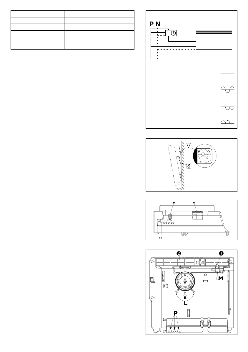
Omezení posuvného voliče
Pro zablokování posuvného voliče, vylomte ve spodní části
regulace kolík (poz.1), posuvný volič nastavte na
požadovanou funkci a tuto polohu tímto kolíkem zajistěte
(poz.2).
Pokyny k použití
Protože je konvektor vybaven termostatem, nevede nastavení
maximální teploty k rychlejšímu nárůstu teploty, ale k přehřátí
místnosti.
Pro větší pohodlí, bez zvyšování spotřeby proudu, by jste
měli nechat všechny přístroje v téže místnosti současně
zapnuté. Při delší nepřítomnosti můžete pro teploty do polohy
«Ochrana před mrazem» (*), aby byla zachována teplota
asi 7°C.
- 7 -
Obr.7
Obr.8
Page 4

poloha přepínače funkcí na konvektoru funkce řídícího vodiče
STOP - vypnuto pilotní vodič nemá vliv
- nočni útlum protizámrazová ochrana a provozní vypnutí
- normální provoz protizámrazová ochrana a provozní vypnutí
- ovládání řídícím vodičem fungují všechny režimy ovládání řídícím
vodičem
ZAPOJENÍ KONVEKTORU CAES S ŘÍDÍCÍM VODIČEM
Polohy přepínače P :
1 - normální provoz (bez řídícího napětí) nebo noční útlum (řídící napětí 230 V) řízený časovačem
2 - režim protizámrazové ochrany (záporné půlvlny - 115 V řídícího napětí )
3 - vypnuto ( kladné půlvlny + 115 V řídícího napětí) Pozor, v této poloze je napětí na vodiči A i B !
Záruční podmínky
Záruční list není součástí přístroje a bude prodejcem dodán samostatně.
Všeobecně platí záruční podmínky stanovené občanským zákoníkem.
Důležité - aby byla záruka platná musí být předložen záruční list.
Záruční list musí být prodejcem při prodeji vyplněn na jméno zákazníka.
- 8 -
Page 5

English
INSTALLING THE CONVECTOR
Position
Since the convector is compliant with the
and IP24
certification logos, it can be installed in all rooms in the house
or apartment.
It is permitted to install it in a bathroom (Fig. 1), provided it is
out of reach of a person using the bathtub or shower.
Comply with the minimum distances indicated in Figure 2.
The unit must not be installed directly beneath a wall socket.
Install the unit away from any air draught, since these
could disturb the electronic settings.
Installing the unit on a wall mounting (figs.3 and 4)
nirewoP
)sttaw(
057-005
0001445,91
05212572
00519543
05715,6624
00024794
llarevO
ssenkciht
)mc(
5,9
llarevO
htgnel
)mc(
73
llarevO
thgieh
)mc(
54
ecnatsiD
A
)mc(
21
ecnatsiD
neewteb
6,52=B
8,51=C
The wall bracket can be used as mounting marker template.
Figure 4.I: With the wall bracket seated on the floor, mark
out on the wall the position of the bottom securing points
(item 1), the hole and the top of the oblong hole (item A).
Figure 4.II: Next, make the template markings by aligning the
two lower oblong holes B onto marking 1 already made on
the wall. The position of the upper attachment points will
then correspond to the position of holes C and D. Secure the
wall support by inserting the 4 screws into holes B, C
and D, checking that the bracket is horizontal.
Fig.1
)mc(CdnaB
Fig.2
Electrical connection
Power supply voltage : 230 V.
Our convectors are delivered with a flexible cable, not
equipped with a plug. It is imperative that the electrical
installation is in compliance with all regulations applicable in
the country concerned.
- 9 -
Fig.3
Fig.4
Page 6

rotcevnocfoepyT
eriwlortnoc
W0051ot0052mm1x3
50AFN
Power supply Economy operating mode
aivelbammargorprotcevnoC
Central
programming
timer
Control wire powered
Temperature decreases
by 3 to 4°C
W0002ot0571mm5.1x3
2
nworb:esahP
eriweulb:lartueN
eriwkcalb:eriwlortnoC
If the cable of food is damaged, it should be replaced by the
manufacturer, his service after sale or a person of similar
qualification to avoid a danger.
Programming by control wire
Our convectors can be connected to any of the programming
devices (timer or programming unit) in accordance with the
diagram of Figures 5 and 6. The control wire is connected to
provide central programming of operation in the comfort and
economy operating modes and, where included in the unit,
"protection against frost".
In units in which the control wire is not connected to a
programming device, for reasons of safety it is vital to insulate
the black wire and in no case connect it to a grounding wire
(green-yellow).
Reminder of standards
The installation must comply with applicable standards. The
installation must not comprise a multiple-pole breaker device
the contact opening gap of which is less than 3 mm.
Attachment of the unit (Fig. 7)
Hook the convector onto the mounting at the bottom and then
push the top part whilst turning the lock (V) towards the
right to block it into position.
TYPE OF SIGNAL
COMFORT OPERATING MODE :
No voltage in control wire
ECONOMY OPERATING MODE : (temp. 3 to 4°C lower)
Control wire voltage 230 V
FROST PROTECTION OPERATING MODE:
(setting: +7°C)
Control wire supplied with 230 V
negative half-wave
LOAD-SHEDDING : convector stopped
Control wire supplied with 230 V
positivE half-wave
Fig.5
Fig.6
Note
Before switching on, check the power connection. We
decline all liability in the event of an incident occurring owing
to incorrect installation.
USING THE CONVECTOR
Starting
Set cursor X to the
position to power up the unit. Set the
thermostat adjustment knob Y so that the marking
corresponding to the temperature desired is visible. The
heating indicator light V1 displays the operating cycles of
the unit. Allow a few hours to pass before making this
adjustment.
- 10 -
Fig.7
Page 7

Locking the thermostat (Fig. 9)
Use of knob
be locked, to prevent tampering of the setting (by children, ...).
a) Dismount the unit from its wall bracket.
b) On the back of the thermostat casing, detach pins P from
their supports.
c) Choose position B to lock the knob, or position L to restrict
the range of use of the knob. Choose one of positions M to
lock the cursor in the mode desired.
YY
Y can be locked or restricted, and cursor X can
YY
Remark :
When starting for the first time, the convector may give off
an unpleasant odour. See that the room is well-aired during
this period.
Manual or automatic control mode :
Control wire not connected :
The unit operates in the mode defined manually by the
5-position switch.
Control wire connected to a clock
or program-ming timer
The unit receives the signal sent by the programming timer
via the control wire.
The following 4 signals are to be distinguished :
Comfort - Economy - Frost protection - Stop
- 4 commands are received when the cursor is in the
position.
- The 'frost protection" and "stop" commands are received
even when the switch is set to the
Tips for use
Since the convector is equipped with a thermostat, choosing
the maximum setting will not increase the temperature any
quicker, but simply overheat the room.
For better heating, and without increasing your power
consumption, allow all the units in the same room to run
simultaneously.
or
position.
Fig.8
Fig.9
In the event of prolonged absence, to protect your house or
apartment from frost and to limit power consumption, you
can set the thermostat to the "frost protection" position (
to maintain a temperature of about 7°C.
- 11 -
)
Page 8

STIEBEL ELTRON
Technik zum Wohlfühlen
Stielbel Eltron
Gesellschaften, Tochtergesellschaften, Vertriembszentren
Bundesrepublik Deutschland
Stiebel Eltron Gesellschaften
Stiebel Eltron International GmbH
Dr-Stiebel-Strabe 37601 Holzminden
Telefon 0 55 31 / 7 02-0
Telefax 0 55 31/7 02-4 79
Europa und Übersee
Stiebel Eltron
Tochtergesellschaftenund
Vertriebszentren
Belgien
Stiebel Eltron Sprl/Bvba
Rue Mitoyenne 897
B 4840 Welkenraedt
Postfach Nr. 133 B-4700 EUPEN
Telefon 0032-(0) 87-881465
Telefax 0032-(0) 87-881597
Frankreich
Stiebel Eltron Internationnal
Succursale Française à Metz
1, rue des Potiers d’Etain
B.P. 5107 F-57073 Metz Cedex
Telefon 00 33/87 74 38 88
Telefax 00 33/87 74 68 26
GroBbritannien
Stiebel Eltron Ltd
Lyveden Road
Brackmills GB-Northampton NN4 7ED
Telefon 00 44/16 04-76 64 21
Telefax 00 44/16 04-76 52 83
VertriebszentrumNordgriechenland
Stiebel Eltron Hellas S.A.
Makedoniasstr.134
Postfach 10516 GR-54248 Thessaloniki
Telefon 00 30/31-31 21 36
Telefax Kundendiens 00 30/31 33 76
Niederlande
Stiebel Eltron NederlandBV
Daviottenweg36
Postbus 2020 NL-5202Cas-Hertogenbosch
Telefon 00 31/73-623 00 00
Telefax Kundendienst 00 31/73-623 11 41
Osterreich
Stiebel Eltron Ges.m.b.H
Moeringgasse 10 A-1150 Wien
Telefon 00 43/9 85 83 90-0
Telefax 00 43/9 85 83 90-9
Polen
Stiebel Eltron.z.o.o.
Ul.Instalatorow 9 P-02-237 Warschau
Telefon 00 48/22-46 69 08
Telefax 00 48/22-46 67 03
Rubland
OCKO
WarenhandelsgesmbH
Kamennostrovskij
Prospekt 50 RUS-197022St. Petersburg
Telefon 0 07/812 234 93 69
Telefax 0 07/812 325 13 46
Schweiz
Stiebel Eltron AG
Netzibodenstr. 23c CH-4133 Pratteln
Telefon 0 61/816 93-33
Telefax 0 61/816 93 44
Spanien
Salvador Escoda S.A
Rosello 430-432 E-08025 Barcelona
Telefon 00 34/(93) 347 55 44
Telefax 00 34/(93) 456 90 32
TschechischeRepublik
Stiebel Eltron spol.s.r.o.
K Hajum 946 CZ-15500 Praha 5
Telefon 00 42-02-6517829
Telefax 00 42-02-6512122
Ungarn
Stiebel Eltron Kft
Bank u.7.1./1. H-1054 Budapest
Telefon 00 36/11 11-48 26/48 43
Telefax 00 36/11 31-19 64
USA
Stiebel Eltron INC
PO BOX 40 TIOGA CENTER NY 13845
Telefon 0 01/6 07-6 87-90 07
Telefax 0 01/6 07-6 87-90 25
New England Sales Office
167 Chestnut street Holyoke MA 01040-4456
Telefon 0 01/413-5 38 78 50
Telefax 0 01/413-5 38 85 55
12-80-0824B - 1328 M 85 B
 Loading...