

Page 1

DW800/820 Operation Manual
STERLING SCALE COMPANY
DW800 HIGH ACCURACY WEIGHT INDICATOR
820 HIGH ACCURACY PIECE COUNTER
USERS MANUAL
AND
_____________________________________________________________________________________________________________
Revision 4.3 Copyright ©2004 Sterling Scale Co., Inc. May 2004
Web Site: www.sterlingscale.com E-mail: [email protected]
Page 2

DW800/820 Operation Manual
Table of Contents
Pages
INSTALLATION-------------------------------------------------------------------------------------------------------1 - 4
Unpacking/Inspecting 1
Load Cell Wiring 2
Universal Bracket 3
880/820 Assembly Drawing 3
Installing the Platter Assembly 2
Connecting External Power Supply 2
Jumper Settings 4
OPERATION-----------------------------------------------------------------------------------------------------------5 - 6
Weighing Operation 5
Weigh Keys 5
Counting Operations 6
Count Keys 6
PARAMETER SETUP AND CALIBRATION------------------------------------------------------------------7 - 10
Parameter Setup 7
Parameter List with Parameter Explanation 7 - 9
Calibration Setup 9-10
PRINTERS--------------------------------------------------------------------------------------------------------------11
Ticket and Tape Printer Driver 11
Model 795 and 895 Printer Driver 11
Model LD-2 Printer Driver 11
COMMUNICATION------------------------------------------------------------------------------------------------- 12 - 16
RS-232 Serial Interface 12
RS-232 Connector 12
Output Protocol 12
Computer Output Format 143
Scoreboard Output Format 14
Remote Control Codes 14
External Zero Switch 14
SPECIFICATIONS--------------------------------------------------------------------------------------------------15 - 16
WARRANY INFORMATION--------------------------------------------------------------------------------------17
_____________________________________________________________________________________________________________
Revision 4.3 Copyright ©2004 Sterling Scale Co., Inc. May 2004
Web Site: www.sterlingscale.com E-mail: [email protected]
Page 3

DW800/820 Operation Manual
PLEASE READ BEFORE ASSEMBLY INSTALLATION
Unpacking and Inspecting
Unpacking and Inspecting
1. Upon receipt of the shipment, check for any shipping damage. If there is damage then
report it to your shipping carrier immediately.
2. Carefully unpack all contents from the shipment.
3. Save all shipping material in case contents require transporting at a later date.
4. The content of the shipment should include the following:
Qty: Item:
1 Instrument with options installed.
1 External power supply if desk mount or NEMA 1 enclosure is provided.
1 Instruction sheet.
1 Hardware kit.
If any of the above items are missing, contact your dealer immediately.
Assembly
The instrumentation is shipped fully assembled. If the unit shipped to you is a desk mount
indicator, it contains a built-in scale and connecting the load cell is not necessary. If you
received a wall mount, a stainless steel or a standard enclosure the load cell may need to be
connected.
Connecting Load Cell
1. Disconnect power to the indicator.
2. Set the unit on a flat surface, open unit and locate “P4” on the lower part of the board.
3. Feed the load cell cable through the strain relief on the left.
4. Connect the load cell cable to the load cell interface connector, “P4” on the
circuit board.
5. Verify that jumpers “J2 and ”J3” are installed on the circuit board.
INSTALLATION
Page 1
_____________________________________________________________________________________________________________
Revision 4.3 Copyright ©2004 Sterling Scale Co., Inc. May 2004
Web Site: www.sterlingscale.com E-mail: [email protected]
Page 4
DW800/820 Operation Manual
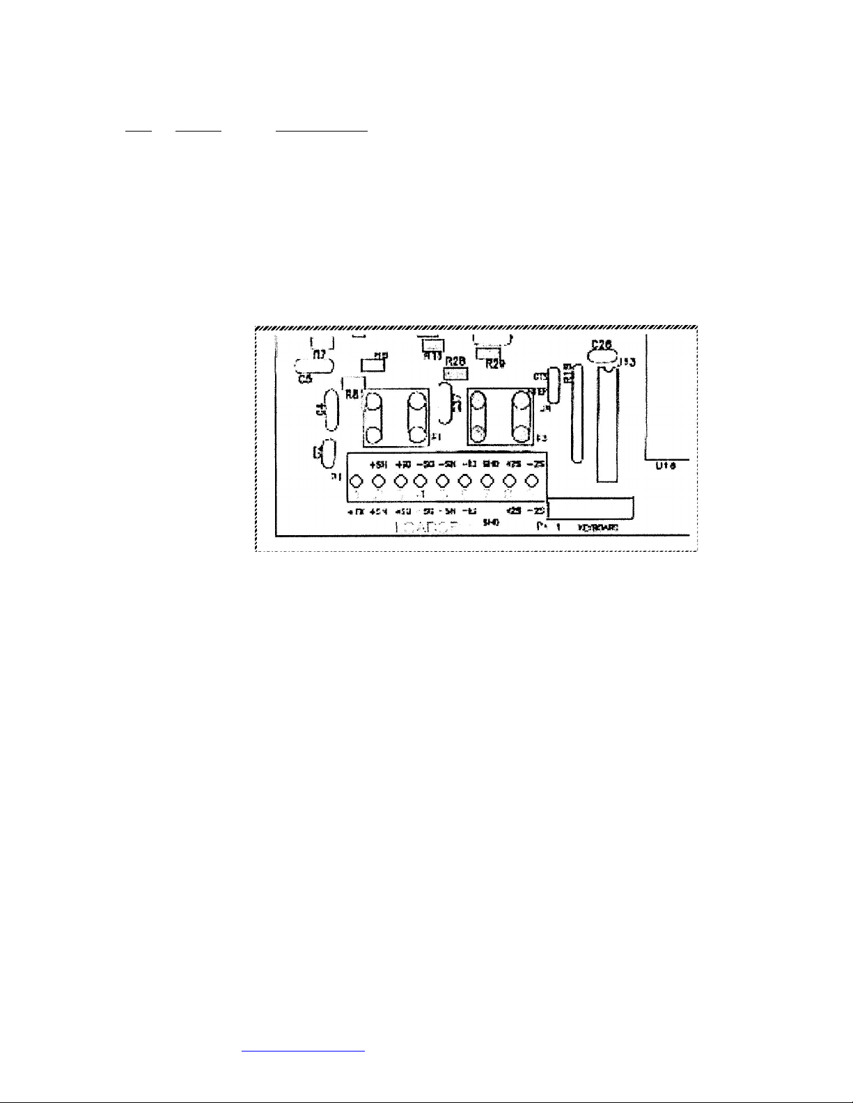
Pin Name Description
1 +EX + Excitation voltage (+10 VDC)
2 +SN(+EX2) + Sense line
3 +SG + Signal line
4 -SG - Signal line
5 -SN(-EX2) - Sense line
6 -EX - Excitation voltage (GND)
7 SHD Shield
8 +SG2 Do not connect
9 -SG2 Do not connect
The load cell interface connector is “P4” on the circuit board,
located in the lower left hand corner.
Connecting External Power Supply
NEMA 1 enclosures are supplied with a transformer power supply, which plugs into the wall.
Power Required – 117 VAC +/- 10 VAC, 60 Hz
NEMA 12 and NEMA 4 enclosures are supplied with a 6’ power cord with a standard 3-prong
connector.
Power Required – 117 VAC +/- 10 VAC, 60 Hz.
Desk enclosures are supplied with a transformer power supply, which plugs into the back of
the instrument and the transformer plugs into the wall.
Power Required – 117 VAC +/- 10 VAC, 60 Hz
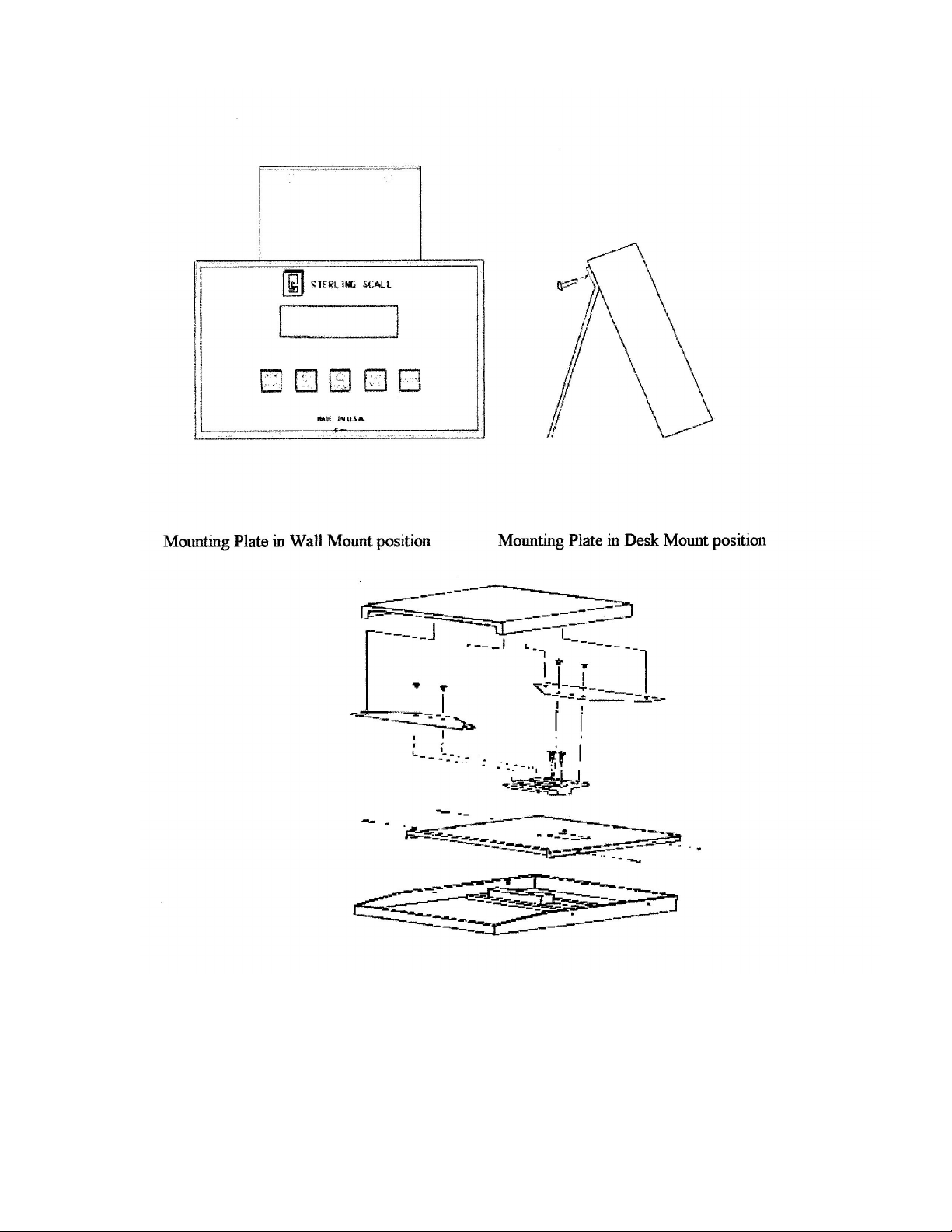
Mounting brackets are supplied with a NEMA 1 standard and NEMA 4 stainless steel
enclosures.
(See diagram on the next page for proper positioning)
INSTALLATION
Page 2
_____________________________________________________________________________________________________________
Revision 4.3 Copyright ©2004 Sterling Scale Co., Inc. May 2004
Web Site: www.sterlingscale.com E-mail: [email protected]
Page 5
DW800/820 Operation Manual
Desktop Enclosure Assembly Drawing
INSTALLATION
PAGE 3
_____________________________________________________________________________________________________________
Revision 4.3 Copyright ©2004 Sterling Scale Co., Inc. May 2004
Web Site: www.sterlingscale.com E-mail: [email protected]
Page 6

DW800/820 Operation Manual
Jumper Settings
In order for the 800/820 to operate as desired hardware, Jumpers must be set properly.
Most of the jumper setting’s are set correctly at the factory and never need to be altered, but
occasionally there is a need to alter a jumper setting, therefore they are shown below
Jumper List
Number Name Setting Description
J1 Back light On Back light on
Off Back light off
J2* Load Cell Sense (+) On Not using load cell sense wires (+)
Off Using load cell sense wires (+)
J3* Load Cell Sense (-) On Not using load cell sense wires (-)
Off Using load cell sense wires (-)
J4* EPROM 256 Use 27C256 EPROM
512 Use 27C512 EPROM
J5 Ground On Chassis ground tied to digital ground
Off Chassis ground not tied to digital ground
J6 RAM 2K Use 2K RAM
8K Use 8K RAM
J7 Not available
J8 NTEP/CTS NTEP Enable NTEP operation
CTS Enable CTS flow control
J9 RAM 8K Use 8K RAM
32K Use 32K RAM
*NOTE: Jumpers J2 and is J8 must both be either connected or disconnected to avoid
improper weighing and/or possible damage to the indicator.
INSTALLATION
Page 4
_____________________________________________________________________________________________________________
Revision 4.3 Copyright ©2004 Sterling Scale Co., Inc. May 2004
Web Site: www.sterlingscale.com E-mail: [email protected]
Page 7
DW800/820 Operation Manual
Weighing Operation
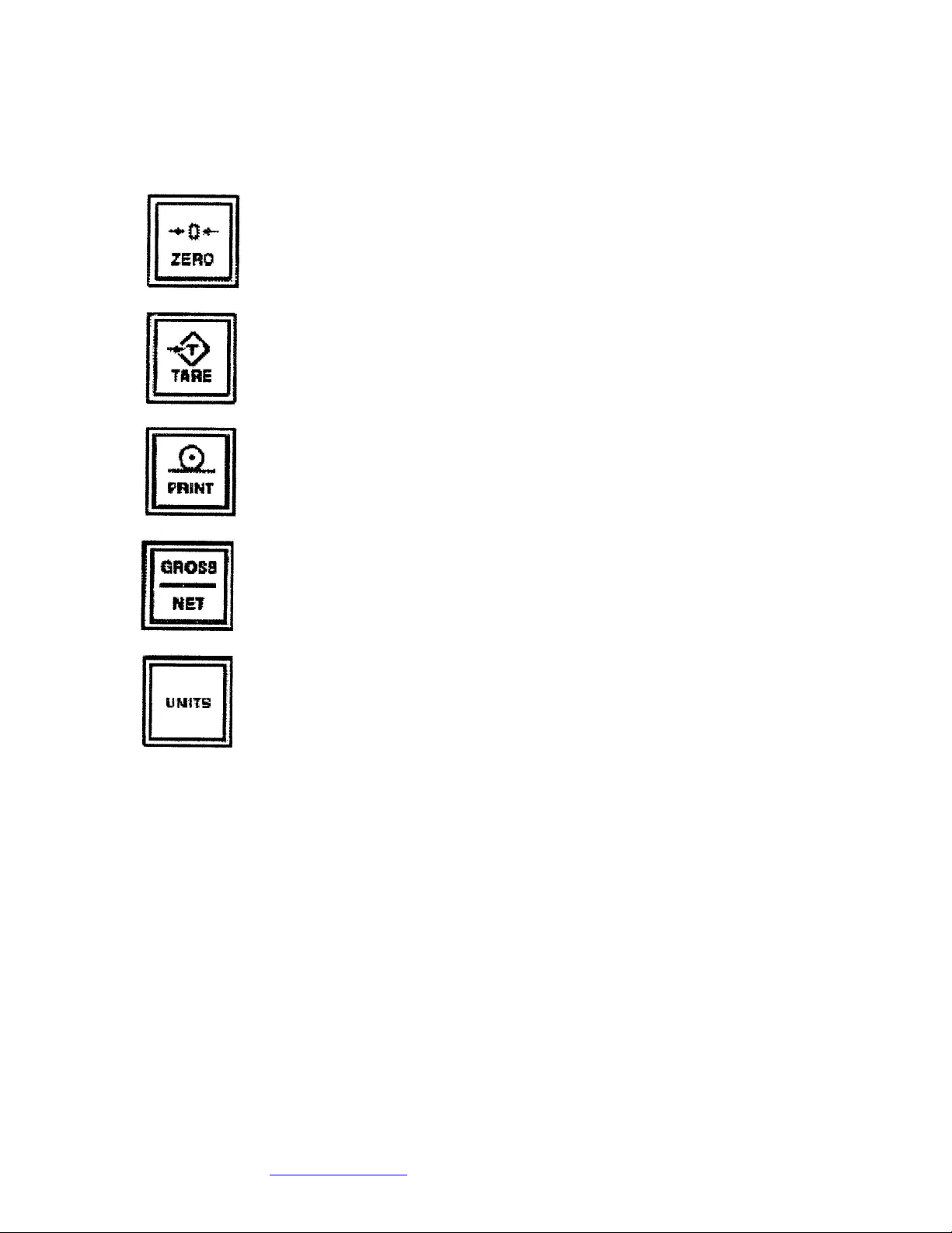
Weigh Keys: During weighing operations the keys are used as follows:
The ZERO key is used to return the scale to the center of zero.
The TARE key is used to tare the weight on the scale. Place the
empty container on the scale and then press the TARE key. The
display will indicate the new weight.
The PRINT key is used to print a weigh ticket.
The GROSS/NET key is used to change the displayed weight from
Gross Wt. (tare + net = gross) to the Net Wt.
(gross – tare = net).
The UNITS key is used to switch between weights, units, lbs., kg.,
grams.
OPERATION
PAGE 5
_____________________________________________________________________________________________________________
Revision 4.3 Copyright ©2004 Sterling Scale Co., Inc. May 2004
Web Site: www.sterlingscale.com E-mail: [email protected]
Page 8
DW800/820 Operation Manual
Counting Operation
The Counting Operation cannot be accessed, if the NTEP parameter is set to True
(see parameter setup) or the Units of Weight parameter is set to LB/KG, LB/G, KG/G, or ALL.
The Count Operation is started by pressing and holding the UNIT key. The indicator will toggle
thru all allowable sample sizes, starting with the current sample size. When the desired
sample size is displayed release the UNIT key. The indicator will sample the pieces and
display the count.
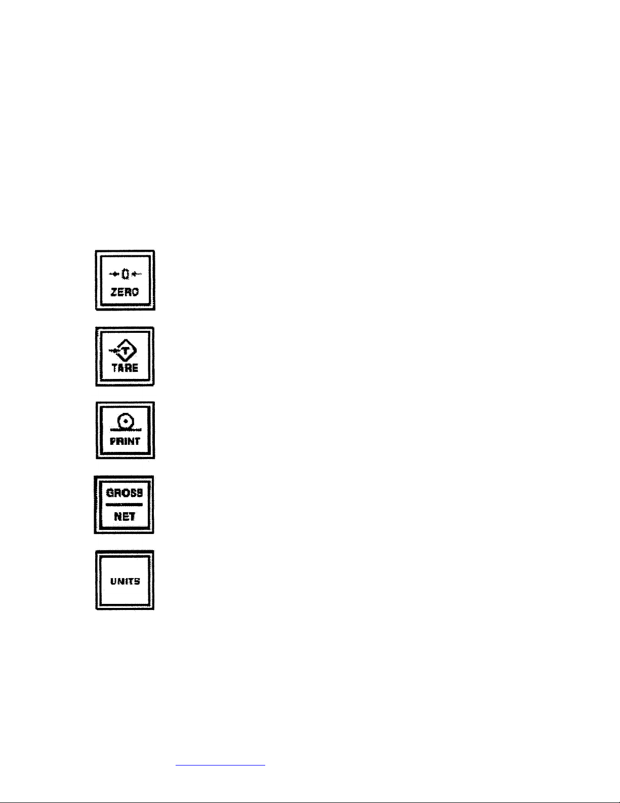
Count Key Operation: During counting operations the key are used as follows:
The ZERO key is used to zero the scale.
The TARE key is used to tare the weight on the scale. Place the
empty container on the scale and then press the TARE key. The
display will indicate the new weight.
The PRINT key is used to print a weight ticket.
The GROSS/NET key is used to change the displayed weight from
Gross Wt. (tare + net = gross) to the Net Wt. (gross – tare = net).
The UNITS key is used to switch count and weigh operation. If held
down the count display will show the average piece weight.
OPERATION
PAGE 6
_____________________________________________________________________________________________________________
Revision 4.3 Copyright ©2004 Sterling Scale Co., Inc. May 2004
Web Site: www.sterlingscale.com E-mail: [email protected]
Page 9
DW800/820 Operation Manual
Parameter Setup Operation
Parameter Setup may be accessed using the following method:
1. From the Weigh Mode press and hold the GROSS/NET key. The DW800/820 displays
“GRSNET” to signify that the GROSS/NET key has been pressed. After approximately
3 seconds the indicator displays “PARAMS” at which time the key may be released.
NOTE: Jumper J8 must be removed from the NTEP position, if NTEP is being utilized, before
access to Parameter Setup is allowed.
2. Once access is allowed to Parameter Setup, the NTEP F parameter
is displayed.
NOTE: NTEP value should always be “F”, unless you are using the NTEP standards.
3. Press the PRINT key to select the desired parameter.
4. Press the TARE key to select the value for the currently selected
parameter.
5. Press the PRINT key to save the currently selected parameter.
6. Repeat steps 3 thru 5 until parameters are set as desired.
7. Press the GROSS/NET key or RESET key to exit Parameter Setup.
Parameter List
Name Values Description
NTEP F If NTEP operation not required
T If NTEP operation required
FCAL F If not calibrating and/or configuring indicator
(Calibration) T if calibrating and/or configuring indicator
NOTE: If True then the DW800/820 will start the calibration routine
PCT 0 Minimum load % disabled
(% of loading) 0.2 If minimum is .2% of full scale capacity
0.5 If minimum is .5% of full scale capacity
1 If minimum is 1% of full scale capacity
NOTE: The value is the minimum weight allowed for parts counting
MSQ 1 Allows any number of samples
(Minimum 2 2 samples required
sample 5 5 samples required
quantity) 10 10 samples required
20 20 samples required
NOTE: The value is the minimum number of samples allowed for an entered sample
size.
_____________________________________________________________________________________________________________
Revision 4.3 Copyright ©2004 Sterling Scale Co., Inc. May 2004
Web Site: www.sterlingscale.com E-mail: [email protected]
Page 10

DW800/820 Operation Manual
PARAMETER SETUP AND CALIBRATION
PAGE 7
Name Values Description
ZT 0 Zero tracking disabled
(Zero Tracking) 0.2 Zero tracking at ± 0.2 graduations
0.6 Zero tracking at ± 0.6 graduations
1 Zero tracking at ± 1 graduations
3 Zero tracking at ± 3 graduations
NOTE: This scale will be re-zeroed within the chosen graduation
DA OFF Digital averaging disabled (Fast display update)
(Digital Average LOW Digital averaging at low (Normal setting for
counting/weighing)
MED Digital averaging at medium Counting/weighing moderate
vibrations)
HI Digital averaging at high (Counting and/weighing
heavy vibrations)
ZR 1.5 Zero range at 1.5 percent of full scale
(Zero Range) 100 Zero range at 100 percent of full scale
U LB. Pounds only
(Units) KG Kilograms only
G Grams only
LB/KG Pounds to Kilogram conversion, counting operation is
disabled
LB/G Pounds to Grams conversion, counting operation is
disabled
KG/G Kilogram to Gram conversion, counting operation is
disabled
ALL Pounds, Kilogram, Grams conversion counting operation
is disabled
MB 0 Motion band disabled (Not recommended for normal
operations)
(Motion Band) 0.1 Motion band at 0.1 graduations (Most sensitive setting
counting)
0.2 Motion band at 0.2 graduations (Counting/weighing with
printer
0.3 Motion band at 0.3 graduations
(Counting/weighing with
printer)
0.4 Motion band at 0.4 graduations (Standard setting)
0.5 Motion band at 0.5 graduations
0.6 Motion band at 0.6 graduations
0.7 Motion band at 0.7 graduations
0.8 Motion band at 0.8 graduations
0.9 Motion band at 0.9 graduations (Least sensitive)
1.0 Motion band at 1.0 graduations (Least sensitive)
OF CMP Computer output format (See Data Interface Section)
(Output Format) SCB Scoreboard output format (See Data Interface Section)
290 Output format for 290 and 695 printers (See Printer Section)
795 Output format for 795 printers * (See Printer Section)
_____________________________________________________________________________________________________________
Revision 4.3 Copyright ©2004 Sterling Scale Co., Inc. May 2004
Web Site: www.sterlingscale.com E-mail: [email protected]
Page 11
DW800/820 Operation Manual
LD2 Output format for LD2 printers *(See Printer Section)
PARAMETERS SETUP AND CALIBRATION
PAGE 8
Name Values Description
CO F On demand output with PRINT key
(Continuous Output) T Continuous output of data. Typically used for computers
or
scoreboards
RD 232 Serial interface is RS-232 (standard)
(Interface) or 20 mA Current Loop (optional)
422 Serial interface is RS-422 (optional)
485 Serial interface is RS-485 (optional)
B 150 Baud rate at 150 bits per second
(Baud Rate) 300 Baud rate at 300 bits per second
600 Baud rate at 600 bits per second
1200 Baud rate at 1,200 bits per second
24000 Baud rate at 2,400 bits per second
48000 Baud rate at 4,800 bits per second
9600 Baud rate at 9,600 bits per second
19200 Baud rate at 19,200 bits per second
P NONE Parity disabled
(Parity) ODD Parity set for odd
EVEN Parity set for even
DBIT 7 Data bits at 7 bits
(Data Bits) 8 Data bits at 8 bits
FC F If not using flow control
(Flow Control) T If using flow control
STTN F If a station number is not required
(Station) T If a station number is required (Choose station 1 – 99)
SN F If the serial number does not need to be changed
(Serial Number) T If the serial number must be changed (Incremented
number for the output)
TIME F If not setting the time and date
(Option) T If setting the time and date
LOCK F If not locking keyboard access to parameters
(Parameter Lockout) T If locking keyboard access to parameters
Used in conjunction with Jumper J8 on the 800 - 820 boards
DR F Dual Range is disabled
(Dual Range) T Dual Range is enabled
Calibration Setup Operation
1. From the Weigh Mode press and hold the GROSS/NET key. The
DW800/820
displays “GRSNET” to signify that the GROSS/NET key has been pressed. After
approximately 5 seconds the indicator displays “PARAMS”, at which time the key
may be released.
_____________________________________________________________________________________________________________
Revision 4.3 Copyright ©2004 Sterling Scale Co., Inc. May 2004
Web Site: www.sterlingscale.com E-mail: [email protected]
Page 12

DW800/820 Operation Manual
2. Once access is allowed to Parameter Setup, the NTEP parameter, along with its current
value is displayed.
NOTE: NTEP should always be set to F, unless used. Press the Print Key to move to the next
parameter.
PARAMETER SETUP AND CALIBRATION
PAGE 9
3. Press the PRINT key or ZERO key to select, FCAL, the scale
calibration and configuration parameter.
4. Next parameter “FCAL F” change to “FCAL T” using the TARE key.
Press the PRINT key to enter the Scale Calibration and Configuration mode.
5. The display shows the current capacity of the scale (Example
“C00100”). The capacity may be changed by using the UNITS, TARE, and ZERO and then
press the PRINT key.
6. The display shows the current graduation size (GR). The graduation size is changed by
pressing the TARE key until the desired value is selected. When the desired graduation size
is selected press the PRINT key.
7. The display shows the current graduation size (U). Select the units to be used for calibrating
with the TARE key. When the desired calibration unit type is selected, press the PRINT key.
8. The display shows “CAL F”. Select “CAL T” using the TARE key. Press the PRINT key
to begin calibrating.
9. The display will repeatedly flash “CLEAR” and “SCALE”.
NOTE: Make sure there is no weight applied at this time. When the scale is clear press the
PRINT key.
10. The display shows “STEP A8”. The indicator will count down to “STEP A0” and then
display
one of the following messages: “ENT LB”, “ENT KG”, or “ENT G”. Lightly Press the PRINT
key to show you the last amount of weight used to calibrate the indicator.
11. The indicator prompts for the calibration weight. The display shows the current calibration
weight. Use the ZERO, TARE, and UNITS keys to select the desired calibration weight. Once
the desired calibration weight is entered, place that weight on the scale and press the PRINT
key.
12. The display shows “STEP B8”. The indicator will count down to “STEP BO” .
13. The indicator is now at the Fine Span Adjust parameter, “SPN 00”.
14. Hit the GROSS/NET key twice to exit parameter setup.
_____________________________________________________________________________________________________________
Revision 4.3 Copyright ©2004 Sterling Scale Co., Inc. May 2004
Web Site: www.sterlingscale.com E-mail: [email protected]
Page 13

DW800/820 Operation Manual
PARAMETER SETUP AND CALIBRATION
Page 10
Printer Drivers
The DW800/820 can be provided with the following optional print drivers. Each driver is
programmed specifically for each printer and will not work with any other printer.
Only the computer and scoreboard outputs are available with any DW800/820 shipped without
a printer.
Ticket and Tape Printer Driver
DW800/820 Program Revision 4.21 – Ticket and Tape Printer Format - Part No. 9500
TIME 10:58 AM Output if time and date option installed
DATE 07-24-98 Output if time and date option installed
GROSS WT. 1.018 lb. *
TARE WT. 0.018 lb. *Output if a tare weight is entered
NET WT. 1.000 lb. *Output if a tare weight is entered
QUANTITY 10 pcs. *Output if in Count Mode
DW800/820 Program Revision 4.22 – Battery Operated Tape Printer Format - Part No. 8951
TIME 10:58 AM Output if time and date option installed
DATE 07-24-98 Output if time and date option installed
GROSS WT. 1.018 lb.
TARE WT. 0.018 lb. *Output if a tare weight is entered
NET WT. 1.000 lb. *Output if a tare weight is entered
QUANTITY 10 pcs. *Output if in Count Mode
DW800/820 Program Revision 4.23 – LD-2 Thermal Label Printer Format - Part No. 9504
TIME 10:58 AM Output if time and date option installed
DATE 07-24-98 Output if time and date option installed
GROSS WT. 1.018 lb.
TARE WT. 0.018 lb. *Output if a tare weight is entered
NET WT. 1.000 lb. *Output if a tare weight is entered
QUANTITY 10 pcs. *Output if in Count Mode
_____________________________________________________________________________________________________________
Revision 4.3 Copyright ©2004 Sterling Scale Co., Inc. May 2004
Web Site: www.sterlingscale.com E-mail: [email protected]
Page 14

DW800/820 Operation Manual
PRINTERS
Page 11
Serial Interface
The DW800/820 has the capability of using one of the following serial interface: RS-232,
RS-422, RS-485, and 20 mA Current Loop. These serial interfaces allow the indicator to be
connected to many different types of serial devices such as printers, computers, and
scoreboards. The standard DW800/820 is equipped with the most common of the serial
interfaces, RS-232.
Output Protocol Format
Baud Rate 150 to 19, 200 Parameter
Start Bits 1 Fixed
Date Bits 7 or 8 Parameter
Parity None, Odd, or Even Parameter
Stop Bits 1 Fixed
The format of the serial data is controlled using the following parameters: Baud Rate, Parity,
and Data Bits.
RS-232
The RS-232 interface is the most commonly used of all serial interfaces and is standard on the
DW800/820. It is used in point-to-point communications where the transmission line is less
than 50 feet. If the RS-232 interface is to be used then the Serial interface parameter must be
set to RS-232 (See Parameter Setup).
Flow control may be used with this interface to regulate the flow of data between the
DW800/820 and another serial device. To enable flow control, set the Flow Control parameter
to True (See Parameter Setup) and Jumper J8 to CTS. The Clear To Send (CTS) input must
then be connected to the compatible flow control output, usually Data Terminal Ready (DTR)
or Request To Send (RTS). The DW800/820 will now only transmit when CTS is high.
RS-232 Connector Pin Assignments
Pin Name Description
01 ZERO External zero
02 Do not connect
03 Do not connect
04 RxD Receive data (input)
05 TxD Transmit data (output)
06 DTR Data Terminal Ready (output)
07 CTS Clear To Send (input)
_____________________________________________________________________________________________________________
Revision 4.3 Copyright ©2004 Sterling Scale Co., Inc. May 2004
Web Site: www.sterlingscale.com E-mail: [email protected]
Page 15

DW800/820 Operation Manual
08 +5VDC +5 Volt DC power
09 GND Digital ground
10 SHIELD Shield
The RS-232 interface connector is P3 on the circuit board
COMMUNICATIONS
Page 12
Output Formats
The DW800/820 is capable of transmitting one of the following formats: Optional Printer
Output Format (See Printer Section), Computer Output Format, and Scoreboard Output
Format. A format may be transmitted either on demand or continuously (See Parameter
Setup). Motion is tested only when transmitting the Printer Output Format on demand.
Computer Output Format
If the Computer Output Format is to be used then the Output Format parameter must be set to
CMP (See Parameter Setup).
The Computer Output Format is as follows:
STX Mode Value Pad Status Units CR LF
Name Characters Description
STX 1 ASCII Start of Text (02 Hex).
Mode 1 “G” if gross weight mode
1 “N” if net weight mode
1 “Q” if quantity (count) mode
Value 7 Displayed weight or quantity
Pad 1 ASCII Space (20 Hex)
Status 1
1
Units 3
3
3
4
“M” if scale is in motion
“0” if scale is in overload. ASCII Space (20 Hex) if scale is stable
“lb.” if in weight mode and unit is pounds. “kg” if in weight mode and unit is kilograms. “g” if in
weight mode and unit is grams, “pcs” if in count mode.
CR 1 ASCII Carriage Return (OD Hex)
LF 1 ASCII Line Feed (OA Hex)
_____________________________________________________________________________________________________________
Revision 4.3 Copyright ©2004 Sterling Scale Co., Inc. May 2004
Web Site: www.sterlingscale.com E-mail: [email protected]
Page 16

DW800/820 Operation Manual
COMMUNICATION
Page 13
Scoreboard Output Format
If the Scoreboard Output Format is to be used then the Output Format parameter must be set
to SCB (See Parameter Setup).
The Scoreboard Output Format is as follows: Value CR LF
Name Characters Description
Value 7 Displayed weight or quantity
CR 1 ASCII Carriage Return (0D Hex)
LF 1 ASCII Line Feed (0A Hex)
External Control
External Keys
The serial interface allows an external device to transmit data (external keys) to the
DW800/820, which mimic the keypad operation completely.
External Key ASCII Value Hex Value Decimal Value
ZERO a 81 097
PRINT b 62 098
UNITS c 63 099
TARE d 64 100
GROSS/NET 9 67 103
PARAMETERS z 7A 122
External Switch
An external switch is a hardware switch used to mimic a keypad operation completely. The
DW800/820 allows for only the ZERO external switch.
A momentary, normally open, switch must be connected between “Pin 01” and “Pin 09”.
External ZERO is activated when the switch is closed.
To avoid erratic operation the switch cable must be less than 10 feet.
_____________________________________________________________________________________________________________
Revision 4.3 Copyright ©2004 Sterling Scale Co., Inc. May 2004
Web Site: www.sterlingscale.com E-mail: [email protected]
Page 17

DW800/820 Operation Manual
COMMUNICATION
Page 14
Specifications
DW800 Physical Specifications
Material: NEMA 1 Enclosure – ABS DFA/R with EMI/RFI shielding
NEMA 4 Enclosure – Stainless steel
NEMA 12 Enclosure – Mild steel
NEMA 7 Enclosure – Cast aluminum
Dimensions: NEMA 1 Enclosure – 6.25” H x 9.5” W x 1.25” D
NEMA 4 Enclosure – 6.25”H x 9.5”W x 2.50”D
NEMA 12 Enclosure – 8.0”H x 10.0”W x 4.0”D
NEMA 7 Enclosure – 14”W x 14”W x 6.00”D
Weight: NEMA 1 Enclosure – 3 lbs.
NEMA 4 Enclosure – 7 lbs
NEMA 12 Enclosure – 10 lbs.
NEMA 7 Enclosure – 50 lbs
Power Requirement: NEMA 1 Enclosure – 12VDC, 500 mA
NEMA 4 Enclosure – 117 VAC ± 10VAC, 60 Hz
NEMA 12 Enclosure – 117 VAC ± 10VAC, 60Hz
NEMA 7 Enclosure – 117 VAC ± 10VAC, 60 Hz
820 Physical Specifications
Dimensions: 12.375” W x 16.55” D x 3.5” H
Power Requirements: 117 VAC ± 10 VAC, 60 Hz
Operating Temperature: -19°C (14 F) to 40° C (104 F)
_____________________________________________________________________________________________________________
Revision 4.3 Copyright ©2004 Sterling Scale Co., Inc. May 2004
Web Site: www.sterlingscale.com E-mail: [email protected]
Page 18

DW800/820 Operation Manual
SPECIFICATIONS
Operational
Internal Counts: 18,777,215
Display Counts: 10,000 recommended (50,000 maximum)
Display Update Rate: 10 times per second
Input Sensitivity: 0.5uV per graduation
Linearity: 0.01% of full scale
Overload Capacity: 105% of full scale
Load Cell Excitation: 10VDC (9,350 ohm load cells or 16,750 ohm load cells)
Calibration
Method: Digital calibration
Range: 0.5 mV/V to 3.0 mV/V
Capacity: 2 to 500,000 lb., kg., or g
Page 15
Display
Type: 6, 14 segment LCD with 20 annuniciators
Enunciators: SCALE 1, 2, 3, 4 GROSS, NET, TARE k, g, lb., pcs,
Backlight: Yellow/Green LED
Serial Interface
Type: RS-232 (bi-directional, full-duplex)
Baud Rate: Selectable from 150 to 19,200 bits per second
Parity: Selectable from none, odd, or even
Data Bits: Selectable from 7 or 8 bits
Start Bits 1
Stop Bits 1
Flow Control Hardware flow control available for RS-232 only
Options
SP3, SP2, SP1, LO BAT, M, -, ID,and ->0<-
*RS-422 (bi-directional, half-duplex)
*RS-485 (bi-directional, half-duplex)
*20mA Current Loop (transmit only)
* Battery Operation
_____________________________________________________________________________________________________________
Revision 4.3 Copyright ©2004 Sterling Scale Co., Inc. May 2004
Web Site: www.sterlingscale.com E-mail: [email protected]
Page 19

DW800/820 Operation Manual
* Time and Date
* RS-422, RS-485, or 20 mA Current Loop
* 4-20 mA or 0 – 10 VDC Analog Output
* 220 VAC, 50 Hz Operation
SPECIFICATIONS
Page 16
WARRANTY
Information
Sterling Scale Company warrants that the DW800/820 shall be free of defects in material and
workmanship for a period of one (1) year from date of shipment.
Sterling Scale Company will repair or replace, at its discretion, free of charge (exclusive of
shipping costs), any equipment covered by this warranty.
This warranty DOES NOT apply if:
1. The DW 800/820 has been repaired or modified by anyone other than Sterling Scale
Company, if in their judgment such repair or modification has detrimentally effected
the performance or reliability of the product.
2. The DW800/820 has been improperly installed or not setup in accordance with the
instructions provided herein.
3. The DW800/820 has been mishandled, abused, or in the judgment of Sterling Scale
Company has been exposed to an environment for which the product was not
designed.
This warranty constitutes Sterling Scale Company’s exclusive warranty, there being no other
warranties, expressed or implied, including any warranty of merchantability or fitness for a
particular purpose.
Sterling Scale Company is not liable for any consequential damages.
Sterling Scale Company reserves exclusive rights to warranty repair determination.
_____________________________________________________________________________________________________________
Revision 4.3 Copyright ©2004 Sterling Scale Co., Inc. May 2004
Web Site: www.sterlingscale.com E-mail: [email protected]
Page 20

DW800/820 Operation Manual
WARRANTY
Page 17
FCC NOTICE
This equipment generates, uses, and can radiate radio frequency energy. If this equipment is
not installed and used in accordance with the instruction manual, it may cause interference to
radio communications. This unit has been type tested and found to comply with the limits for a
Class A computing device pursuant to Subpart J of Part 15 of FCC Rules, which are designed
to provide reasonable protection against such interference in a commercial environment.
Operation of this equipment in a residential area is likely to cause interference, in which case
the user, at his own expense: will be required to take whatever measures may be required to
correct the interference.
DISCLAIMER
All rights reserved. Reproduction or use, without express permission, of editorial or pictorial
content, in any manner, is strictly prohibited. No patent liability is assumed with respect to the
use of the information contained herein. While every precaution has been taken in the
preparation of this manual, we assume no responsibility for errors or omissions. Neither is any
liability assumed for damages resulting from the use of the information contained herein. All
information has been checked for accuracy and ease of application. Since success and safety
in applying the equipment depend upon individual accuracy, skill and caution, we are not able
to guarantee the results of any procedure contained herein. Nor can we assume responsibility
for damage to property or injury to persons engaging from the procedures. Persons engaging
from the procedures do so entirely at their own risk.
_____________________________________________________________________________________________________________
Revision 4.3 Copyright ©2004 Sterling Scale Co., Inc. May 2004
Web Site: www.sterlingscale.com E-mail: [email protected]
Page 21

DW800/820 Operation Manual
Page 18
_____________________________________________________________________________________________________________
Revision 4.3 Copyright ©2004 Sterling Scale Co., Inc. May 2004
Web Site: www.sterlingscale.com E-mail: [email protected]
 Loading...