


 Loading...
STERLING SCALE COMPANY
810 HIGH ACCURACY WEIGHT INDICATOR
AND
825 HIGH ACCURACY PIECE COUNTER
USERS MANUAL
_____________________________________________________________________________________________________________
Revision 4.4 |
Copyright ©2004Sterling Scale Co., Inc. |
March 2005 |
Web Site: www.sterlingscale.com |
E-mail: sales@sterlingscale.com |
|
Table of Contents |
|
|
|
|
Pages |
INSTALLATION------------------------------------------------------------------------------------------------ |
|
1- 4 |
Unpacking/Inspecting |
|
1 |
Load Cell Wiring |
|
2 |
Connecting Scale 2 |
|
2 |
Connecting External Power Supply |
|
2 |
DW810 Universal Bracket |
|
3 |
810/825 Assembly Drawing |
|
3 |
Installing the Platter Assembly |
|
3 |
Jumper Settings |
|
4 |
PARAMETER SETUP AND CALIBRATION----------------------------------------------------------- |
|
5 - 12 |
Parameter Setup |
|
5 |
Parameter List with Parameter Explanation |
|
5 – 11 |
Calibration Setup |
|
11 |
OPERATION --------------------------------------------------------------------------------------------------- |
|
13 -18 |
Weighing Operation |
|
13-14 |
Weigh Keys |
|
9-12 |
Counting Operation |
|
15 |
Count Mode Keys |
|
15 |
Typical Fixed Sample Counting Operation |
|
16 |
Typical Variable Sample Counting Operation |
|
17 |
Typical Reverse Counting Operation |
|
17 |
Typical Average Piece Weight Counting Operation |
18 |
|
ID Numbers |
|
18 |
PRINTERS ------------------------------------------------------------------------------------------------------ |
|
19 -22 |
Ticket and Tape Printer Driver |
|
19 |
Model 795 and 895 Printer Driver |
|
20 |
Model LD-2 Printer Driver |
|
21 |
COMMUNICATION ------------------------------------------------------------------------------------------- |
|
23 - 25 |
RS-232 Serial Interface |
|
23 |
RS-232 Connector |
|
23 |
Output Protocol |
|
23 |
Computer Output Format |
|
24 |
Scoreboard Output Format |
|
25 |
Remote Control Codes |
|
25 |
External Zero Switch |
|
25 |
SPECIFICATIONS -------------------------------------------------------------------------------------------- |
|
26 - 27 |
WARRANY INFORMATION -------------------------------------------------------------------------------- |
|
28 |
_____________________________________________________________________________________________________________ |
||
Revision 4.4 |
Copyright ©2004Sterling Scale Co., Inc. |
March 2005 |
Web Site: www.sterlingscale.com |
E-mail: sales@sterlingscale.com |
|
PLEASE READ BEFORE ASSEMBLY INSTALLATION
Unpacking and Inspecting
Unpacking and Inspecting
1.Upon receipt of the shipment, check for any shipping damage. If there is damage then report it to your shipping carrier immediately.
2.Carefully unpack all contents from the shipment.
3.Save all shipping material in case contents require transporting at a later date.
4.The contents of the shipment should include the following:
Qty: Item:
1 Instrument with options installed.
1 External power supply if desk mount or NEMA 1 enclosure is provided.
1 Instruction sheet.
1 Hardware kit.
If any of the above items are missing, contact your dealer immediately.
Assembly
The instrumentation is shipped fully assembled. If the unit shipped to you is a desk mount indicator, it contains a built-in scale and connecting the load cell is not necessary. If you received a wall mount, a stainless steel, or a standard enclosure the load cell may need to be connected.
Connecting Load Cell
1.Disconnect power to the indicator.
2.Set the unit on a flat surface, open unit and locate “P4” on the lower part of the board.
3.Feed the load cell cable, through the strain relief on the left.
4.Connect the load cell cable to the load cell interface connector, “P4” on the circuit board.
5.Verify that jumpers “J2” and “J3” are installed on the circuit board.
INSTALLATION
Page 1
_____________________________________________________________________________________________________________
Revision 4.4 |
Copyright ©2004Sterling Scale Co., Inc. |
March 2005 |
Web Site: www.sterlingscale.com |
E-mail: sales@sterlingscale.com |
|
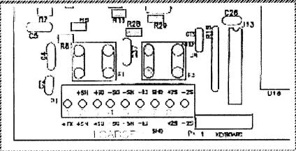
Pin |
Name |
Description |
1 |
+EX |
+ Excitation voltage (+10 VDC) |
2 |
+SN(+EX2) |
+ Sense line (+Excitation scale 2) |
3 |
+SG |
+ Signal line |
4 |
-SG |
- Signal line |
5 |
-SN(-EX2) |
- Sense line (-Excitation scale 2) |
6 |
-EX |
- Excitation voltage (GND) |
7 |
SHD |
Shield |
8 |
+SG2 |
(+Signal scale 2) |
9 |
-SG2 |
(-Signal scale 2) |
The load cell interface connector is P4 on the circuit board, located in the lower left hand corner.
Connecting Scale 2
Scale 2 is an option on the 825. Scale 2 does not use sense wires. Scale 2 can be connected following the above pin assignments.
Please Note: The +SN and – SN terminals are used to provide + and – Excitation to the second scale.
Connecting External Power Supply
-NEMA 1 enclosures are supplied with a transformer power supply, which plugs into the wall.
Power Required – 117 VAC ! 10 VAC, 60 Hz
-NEMA 12 and NEMA 4 enclosures are supplied with a 6’ power cord with a standard 3-prong connector.
Power Required – 117 VAC ! 10 VAC, 60 Hz
-Desk enclosures are supplied with a transformer power supply, which plugs into the back of the instrument and the transformer plugs into the wall.
Power Required – 117 VAC ! 10 VAC, 60 Hz
INSTALLATION
Page 2
_____________________________________________________________________________________________________________
Revision 4.4 |
Copyright ©2004Sterling Scale Co., Inc. |
March 2005 |
Web Site: www.sterlingscale.com |
E-mail: sales@sterlingscale.com |
|

Mounting brackets are supplied with the NEMA 1 standard and NEMA 4 stainless steel enclosures.
(See diagram for proper positioning)
INSTALLATION
Page 3
_____________________________________________________________________________________________________________
Revision 4.4 |
Copyright ©2004Sterling Scale Co., Inc. |
March 2005 |
Web Site: www.sterlingscale.com |
E-mail: sales@sterlingscale.com |
|
Jumper Settings
In order for the 810/825 to operate as desired hardware, Jumpers must be set properly. Most of the jumper setting’s are set correctly at the factory and never need to be altered, but occasionally there is a need to alter a jumper setting, therefore they are shown below
Jumper List
Number |
Name |
Setting |
Description |
J8 |
NTEP/CTS |
NTEP |
Enable NTEP operation |
|
|
CTS |
Enable CTS flow control |
J9 |
RAM |
8K |
Use 8K RAM |
|
|
32K |
Use 32K RAM |
J10 |
EPROM |
256 |
Use 27C256 EPROM |
|
|
512 |
Use 27C512 EPROM |
J12 |
Back light |
On |
Back light on |
|
|
Off |
Back light off |
J13* |
Load Cell Sense (+) |
On |
Not using load cell sense wires (+) |
|
|
Off |
Using load cell sense wires (+) |
J14* |
Load Cell Sense (-) |
On |
Not using load cell sense wires (-) |
|
|
Off |
Using load cell sense wires (-) |
*NOTE: Jumpers “J13” and “J14” must both be either connected or disconnected to avoid improper weighing and/or possible damage to the indicator.
INSTALLATION
Page 4
_____________________________________________________________________________________________________________
Revision 4.4 |
Copyright ©2004Sterling Scale Co., Inc. |
March 2005 |
Web Site: www.sterlingscale.com |
E-mail: sales@sterlingscale.com |
|

Parameter Setup Operation
Parameter setup may be accessed using the following method:
1.From the Weigh Mode press and hold the GROSS/NET key. The DW810/825 displays “GRSNET” to signify that the GROSS/NET key has been pressed. After approximately 3 seconds the indicator displays “PARAMS” at which time the key may be released. If the indicator responds with the message “LOCKED”, then Jumper “J8”
is the wrong position. Jumper “J8” must be removed before access to Parameter Setup is allowed. (See Jumper Settings)
2.Once access is allowed to Parameter Setup, the NTEP F parameter along with its
current value is displayed.
NOTE: Always set to “F” unless factory set.
3.Press the PRINT key to select the desired parameter.
4.Press the TARE key to select the value for the currently selected parameter.
5.Press the PRINT key to save the currently selected parameter.
6.Repeat steps 3 thru 5 until parameters are set as desired.
7.Press the GROSS/NET key or RESET key to exit Parameter Setup.
Parameter List
PARAMETER SETUP AND CALIBRATION
Page 5
_____________________________________________________________________________________________________________
Revision 4.4 |
Copyright ©2004Sterling Scale Co., Inc. |
March 2005 |
Web Site: www.sterlingscale.com |
E-mail: sales@sterlingscale.com |
|
Name |
Values |
Description |
ZT |
0 |
Zero tracking disabled |
(Zero Tracking) |
0.2 |
Zero tracking at ± 0.2 graduations |
|
0.6 |
Zero tracking at ± 0.6 graduations |
|
1 |
Zero tracking at ±1 graduation |
|
3 |
Zero tracking at ± 3 graduations |
|
|
This scale will be re-zeroed within the chosen graduation |
DA |
OFF |
Digital averaging disabled. (Fast update – recommended for applications |
(Digital Average) |
|
where speed is a prime consideration, such as filling operations) |
|
LOW |
Digital averaging at low (Norma setting for parts counting) |
|
MED |
Digital averaging at medium (Normal weighing applications) |
|
HI |
Digital averaging at hi (Recommended for areas with heavy vibrations) |
ZR |
1.5 |
Zero range at 1.5 percent of full scale |
(Zero Range) |
100 |
Zero range at 100 percent of full scale |
U |
LB. |
Pounds only |
(Units) |
KG |
Kilograms only |
|
G |
Grams only |
|
LB/KG |
Pounds to Kilogram conversion |
|
LB/G |
Pounds to Grams conversion |
|
KG/G |
Kilogram to Gram conversion |
|
ALL |
Pounds, Kilogram, Grams conversion counting operation |
|
|
is disabled |
MB |
0 |
Motion band disable (Not recommended for normal operations) |
(Motion Band) |
0.1 |
Motion band at 0.1 graduations (Most sensitive setting counting) |
|
0.2 |
Motion band at 0.2 graduations (Counting and weighing with printer) |
|
0.3 |
Motion band at 0.3 graduations (Light vibrations and air movement |
|
0.4 |
Motion band at 0.4 graduations (Standard setting) |
|
0.5 |
Motion band at 0.5 graduations |
|
0.6 |
Motion band at 0.6 graduations |
|
0.7 |
Motion band at 0.7 graduations |
|
0.8 |
Motion band at 0.8 graduations |
|
0.9 |
Motion band at 0.9 graduations (Least sensitive) |
|
1.0 |
Motion band at 1.0 graduations (Least sensitive) |
SM |
OFF |
Setpoint Off |
(Setpoint Mode) |
CUT |
Setpoints set for cutoff operations |
|
COM |
Setpoints set for comparator operations |
SA |
NO |
Normally open |
(Setpoint Activation) |
NC |
Normally closed |
SD |
QTY |
Setpoints operate will quantity displayed |
(Setpoint Data) |
GRS |
Setpoints operate with gross displayed |
|
NET |
Setpoints operate with net displayed |
SS |
F |
Setpoints will activate even when the scale is in motion |
(Setpoint Stable) |
T |
Setpoints will activate only when the scale is stable |
PARAMETERS SETUP AND CALIBRATION
Page 6
_____________________________________________________________________________________________________________
Revision 4.4 |
Copyright ©2004Sterling Scale Co., Inc. |
March 2005 |
Web Site: www.sterlingscale.com |
E-mail: sales@sterlingscale.com |
|
Name |
Values |
Description |
OF |
CMP |
Computer output format |
(Output Format) |
SCB |
Scoreboard output format |
|
1* 290 |
Output format for 290 and 695 printers* (See Printer Section) |
|
1* 695 |
Output format for 795 printers* (See Printer Section) |
|
1*LD2 |
Output format for LD2 printers* (See Printer Section) |
CO |
F |
On demand output with PRINT key |
(Continuous Output) |
T |
Continuous output of data (Typically used with computer and scoreboards) |
RS |
232 |
Serial interface is RS-232 (Standard) |
(Interface) |
|
or 20 mA current loop (Optional) |
|
422 |
Serial interface is RS-422 (Optional) |
|
485 |
Serial interface is RS-485 (Optional) |
B |
150 |
Baud rate at 150 bits per second |
(Baud Rate) |
300 |
Baud rate at 300 bits per second |
|
600 |
Baud rate at 600 bits per second |
|
1200 |
Baud rate at 1,200 bits per second |
|
2400 |
Baud rate at 2,400 bits per second |
|
4800 |
Baud rate at 4,800 bits per second |
|
9600 |
Baud rate at 9,600 bits per second |
|
19200 |
Baud rate at 19,200 bits per second |
P |
NONE |
Parity disabled |
(Parity) |
ODD |
Parity set for odd |
|
EVEN |
Parity set for even |
DBIT |
7 |
Data bits at 7 bits |
(Data Bits) |
8 |
Data bits at 8 bits |
FC |
F |
If not using flow control |
(Flow Control) |
T |
If using flow control |
STTN |
F |
If a station number is not required |
(Station) |
T |
If a station number is required (Choose station 1 – 99) |
SN |
F |
If the serial number does not need to be changed |
(Serial Number) |
T |
If the serial number must be changed (Incremented number for the output) |
|
|
|
SMP |
F |
If not changing the sample scale |
(Sample Scale) |
T |
If changing the sample scale |
|
|
(Counting operation only) |
CNT |
F |
If not changing the count scale |
(Count Scale) |
T |
If changing the count scale |
|
|
(Counting operation only) |
TIME |
F |
If not setting the time and date |
(Option) |
T |
If setting the time and date |
LOCK |
F |
If not locking keyboard access to parameters |
(Parameter Lockout) |
T |
If locking keyboard access to parameters |
|
|
Used in conjunction with Jumper J8 on the 810825 boards |
DR |
F |
Dual Range Disabled |
(Dual Range) |
T |
Dual Range Enabled |
1* Available only with Print Drivers (See Printer Section)
PARAMETER SETUP AND CALIBRATION
Page 7
_____________________________________________________________________________________________________________
Revision 4.4 |
Copyright ©2004Sterling Scale Co., Inc. |
March 2005 |
Web Site: www.sterlingscale.com |
E-mail: sales@sterlingscale.com |
|
Parameter Explanation
NTEP
Selects Natinonal Type Evaluation Program (NTEP) mode.
FCAL
Scale Calibration and Configuration (see calibration setup).
ZT
Zero tracking automatically zeros the scale approximately once a second if the gross weight is less than the selected number of graduations from current zero. This parameter is used to correct zero errors due to load cell drift, temperature changes, or deadload drift
(dust, evaporation, …).
DA
Digital averaging is used to “smooth out” the displayed weight reading. Increasing digital
Averaging will stabilize the weight reading if mechanical vibration is present.
ZR
Zero range selects the percent of full scale capacity, which is allowed to be zeroed,
Referenced to the calibration point.
U
Units of weight selects the units to be displayed.
MB
Motion band is used to set how stable the scale must be to perform certain scale Operations (zero, tare, print, …). The motion on the scale must be less than the selected number of graduations to perform the scale operation.
SM
Selects the setpoint mode. Three setpoint outputs is an option on the 810/825.
SA
Selects the setpoint activation. Three setpoint outputs is an option on the 810/825.
SD
Selects the setpoint data. Three setpoint outputs is an option on the 810/825.
SS
Selects setpoint stability. Three setpoint outputs is an option on the 810/825.
OF
Selects the format to be output (see COMMUNICATION: Output Formats).
PARAMETER SETUP AND CALIBRATION
Page 8
_____________________________________________________________________________________________________________
Revision 4.4 |
Copyright ©2004Sterling Scale Co., Inc. |
March 2005 |
Web Site: www.sterlingscale.com |
E-mail: sales@sterlingscale.com |
|
Loading...