

Page 1
INSTALLATION INSTRUCTIONS & PARTS LIST
OIL FIRED UNIT HEATERS
MODELS: QVOF (50, 84, 100, 140, 180, 250)
ATTENTION: READ THIS MANUAL AND ALL LABELS ATTACHED TO THE UNIT CAREFULLY BEFORE
ATTEMPTING TO INSTALL, OPERATE OR SERVICE THESE UNITS! CHECK UNIT DATA PLATE FOR ELECTRICAL
SPECIFICATIONS AND MAKE CERTAIN THAT THESE AGREE WITH THOSE AT POINT OF INSTALLATION. RECORD
THE UNIT MODEL AND SERIAL No.(s) IN THE SPACE PROVIDED. RETAIN FOR FUTURE REFERENCE.
IIOF-1
Model No.
Serial No.
FOR YOUR SAFETY
The use and storage of gasoline or other flammable vapors and liquids in open containers in
the vicinity of this appliance is hazardous.
WARNING: Improper installation, adjustment, alteration, service or maintenance can
cause property damage, injury or death. Read the installation, operating and
maintenance instructions thoroughly before installing or servicing this equipment.
WARNING: Install, operate and maintain unit in accordance with manufacturer's
instructions to avoid exposure to fuel substances or substances from incomplete
combustion which can cause death or serious illness. The state of California has
determined that these substances may cause cancer, birth defects, or other
reproductive harm.
INSTALLER'S RESPONSIBILITY
Installer Please Note: This equipment has been test fired and inspected. It has been
shipped free from defects from our factory. However, during shipment and installation,
problems such as loose wires, leaks or loose fasteners may occur. It is the installer's
responsibility to inspect and correct any problems that may be found.
RECEIVING INSTRUCTIONS
Inspect shipment immediately when received to determine if any damage has occurred to the
unit during shipment. After the unit has been uncrated, check for any visible damage to the
unit. If any damage is found, the consignee should sign the bill of lading indicating such
damage and immediately file claim for damage with the transportation company.
HVAC EQUIPMENT
260 NORTH ELM STREET/WESTFIELD, MA 01085
TEL: (413) 564-5540 FAX: (413) 562-5311
Page 2

Sterling oil powered Unit Heaters are shipped in a heavy
duty reinforced corrugated shipping crate. Upon receiving
your unit, a careful inspection of this crate should be
made to ascertain if there is any damage either external
or concealed.
The thermostat should be mounted away from the blower
air stream on an inside wall or partition approximately 5
feet above the floor.
3 – FUEL OIL PIPING
All Unit Heaters come completely assembled and wired.
GENERAL INFORMATION
Oil Fired Unit heaters are designed to be suspended.
However, they can be installed on approved fire-resistive
slabs or supports having no combustible material against
the underside of the unit. Other clearances to
combustible sources should be not less than 6″ from
sides and top and 18″ from flue pipe in any direction.
When suspending the unit from a ceiling, an allowance
of 18″ from the top of the unit should be made to
accommodate a barometric draft regulator.
Unit Heaters should not be subjected to negative
pressures (drafts) created by room or building exhaust
fans. Sufficient air for combustion is an important
consideration.
Special attention must be given to those installations,
such as service stations and warehouses, where the
units have short stacks since the draft may not be
adequate.
When the vertical distance from the fuel supply tanks to
the fuel unit on the burner is more than 15 feet, or
when a multiple installation is required, the fuel system
should include a boost pump. See Figure 2.
INSTALLATION PROCEDURE
1 – HANGING OF UNIT
Welded to the top of the heat exchanger at each corner
is a 3/4″ pipe coupling which will accommodate a
standard 3/4″ pipe nipple. There are many ways the
suspension of a unit can be accomplished. However,
care should be taken to be sure the supporting beams
or girders are of ample strength to support the weight
of the unit. It is good practice to distribute the weight
over several girders rather than depending on one.
2 – WIRING
As this is a prewired unit, all controls, with the exception
of the thermostat are mounted and wired. 115 volt
service to utility box on unit heater is required. Unit
should be fused independent of other fixtures,
equipment, etc. There is a service switch on the unit.
An additional switch should be provided at the room or
building entrance.
a) Gravity Systems
Gravity systems where fuel supply is on the same level
as unit, require one line from tank to burner. This should
be 1/2″ or 3/8″ O.D. tubing or 3/8″ iron pipe according
to local codes. There should be a hard seat globe valve
at tank. A Main line oil filter should be installed
immediately after valve. Another valve, either hard seat
globe or heat responsive, should be installed at burner.
Local codes must be adhered to.
b) Lift Systems
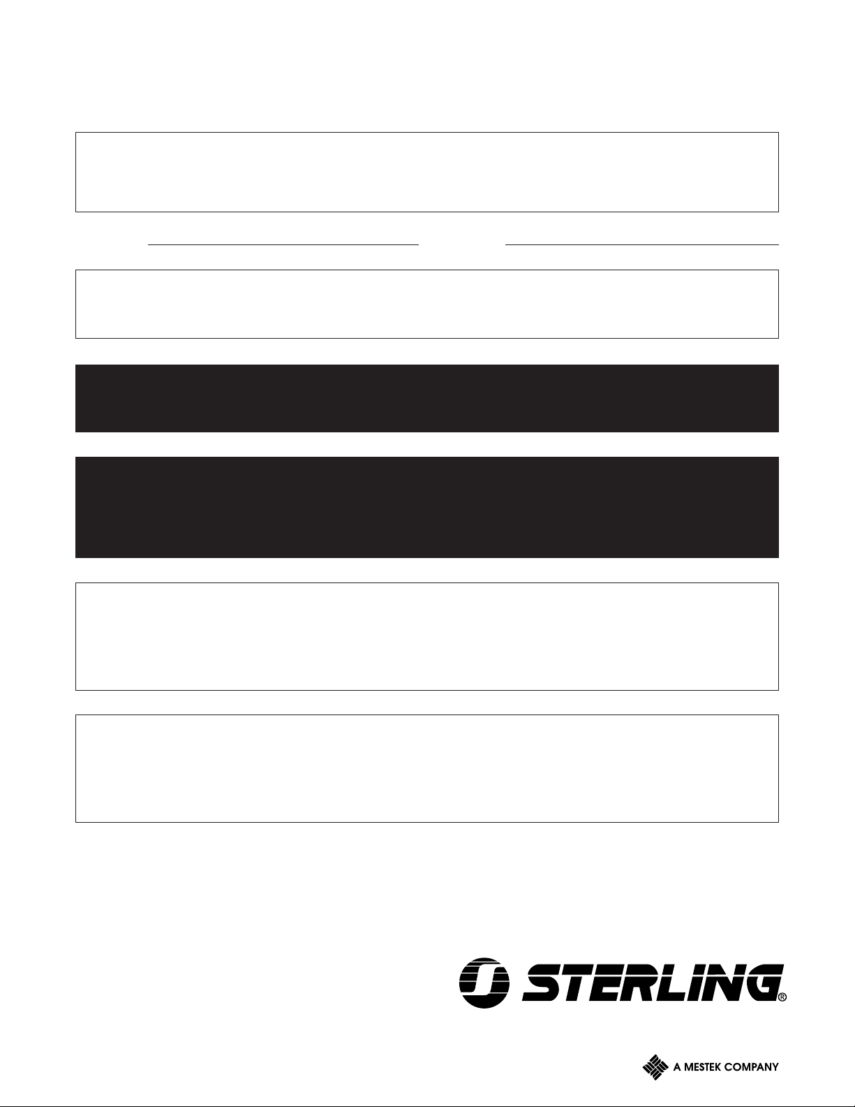
Lift systems where fuel supply tank is below unit, require
a two-pipe system. See Figure 1.
Suction and return lines should originate no less than
2″ nor more than 4″ from bottom of fuel tank. If code
permits, 1/2″ O.D. soft tubing should be used. A doubletapped bushing should be used in tapping of tank with
a slip connector so that both lines are continuous from
bottom of tank to inside of building.
A good quality ball check valve should be in the suction
line immediately inside of building.
Care should be exercised in installing lines in tank so
that they do not curl up inside of tank.
Lines should continue to burner either as copper tubing
or black pipe, depending on local codes, and should be
run straight and direct, eliminating need for bends or
elbows as much as possible. Lines should be securely
fastened to eliminate vibration and/or sagging.
Be sure bypass plug is installed in proper place, tightly
secured. See instruction sheet attached to pump for
more detail. On all connections, use oil resistant joint
compound. Either hard seat globe valve or heat
responsive valve (Firomatic or equal), depending on
code, should be installed in suction line as close to
pump as practicable.
A boost pump should be used on multiple unit heater
installations, or where an installation has more than a
15 foot lift (measured from the suction line in fuel tank
to the fuel unit on the burner). See Figure 2
2
Page 3
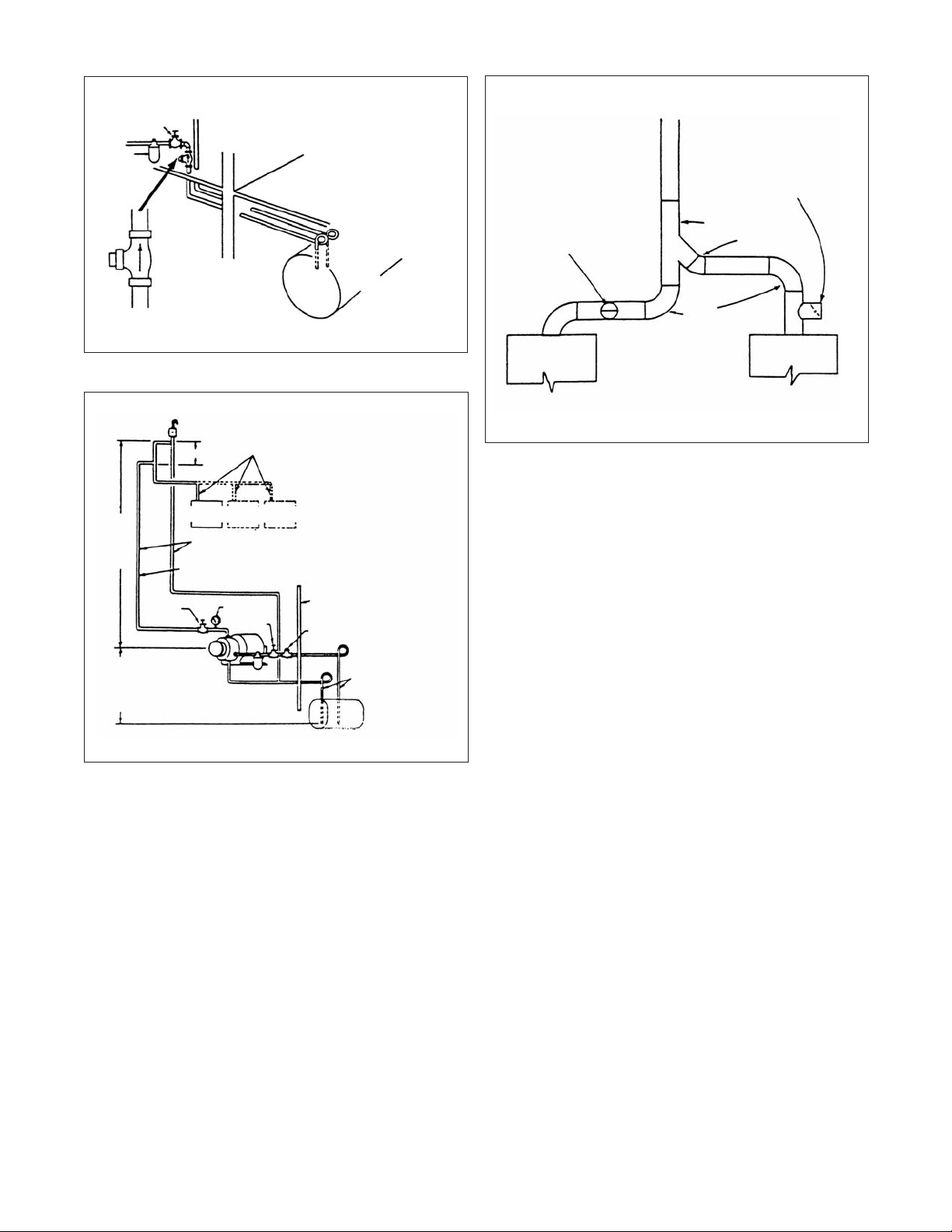
Figure 1 - Fuel Oil Piping.
Figure 3
VALVE
FILTER
GROUND LEVEL
CHECK VALVE
(ENLARGED)
BURNED
FUEL OIL
TANK
Figure 2 - Piping Overhead System
VACUUM BREAKER
35 FT. MAX.
PRESSURE HEAD
(OPTIONAL)
15 FT. MAX.
SUCTION LIFT
VALVE
LINE PRESSURE
NOT TO EXCEED 6 PSI
2 – 4 FT.
FURNACE
FURNACE
NO. 1
NO. 2
1/2" O.D. COPPER TUBING
SUPPLY LINE
COMPOUND
GAUGE
VALVE
PUMP
FILTER
RETURN LINE
FURNACE
NO. 3
WALL
CHECK VALVE
INLET
LINE
RETURN LINE
SUCTION AND
RETURN LINE
CLEARANCE FROM
BOTTOM OF TANK
MINIMUM 2"
MAXIMUM4"
1/2" O.D. COPPER TUBING
SUCTION AND RETURN
LINE CLEARANCE FROM
BOTTOM OF TANK
TANK
MINIMUM 2"
MAXIMUM 4"
TO ROOF
BAROMETRIC
DRAFT
REGULATOR
BAROMETRIC
DRAFT
REGULATOR
"Y"
45° L
90°
UNIT 1 UNIT 1
4 – FLUE CONNECTIONS
Connect flue pipe to chimney. If chimney is masonry
type, be sure base is clean of debris and that opening
through tile is at least as large as flue pipe (see
specification sheet).
Chimney, either masonry or pre-fab, should be in
accordance with local requirements. The flue gas exit
of a chimney shall be at least 3 feet above the highest
point where the chimney passes through the roof of a
building, and at least 2 feet higher than any portion of a
building within 10 feet of the chimney. Chimney should
not be connected to an open fireplace, but could serve
two heating units.
NOTE: When two units are connected to a common
chimney, they should be connected as shown in
Figure 3.
Barometric draft regulator should be installed in flue
pipe, Regulator should be installed in run of flue pipe,
either horizontal or vertical. It is poor practice to install
in a tee that is substituted for an elbow as this has a
tendency to puff odors out of regulator on starts.
Special attention must be given to those installations
such as service stations and warehouses where units
are suspended at ceiling level. Because of the height
restrictions on the chimney, draft is not adequate.
Available for these installations is a draft inducer and
prover at additional cost.
3
Page 4

5 – FAN AND LIMIT CONTROL SETTING
A good rule to follow is to use lowest limit setting that
will assure enough heat and use lowest fan settings
that will not circulate cool air before fan stops.
The recommended setting is: Limit 200 degrees, fan on
130 degrees; fan off 90 degrees.
6 – STARTING AND TESTING OF UNIT
Before starting burner, it is advisable to remove nozzle
assembly and check nozzle size (see nozzle
specifications label on unit) and setting of electrodes.
Put 5 to 10 drops of good quality SAE 20 motor oil
(Havoline) in the oil cups at each end of the motor.
Repeat oiling of motor at the start and mid-point of
each heating season.
7 – TO PRIME FUEL UNIT
Place a can under valve of fuel unit and open bleed
valve one-quarter turn. Make certain all fuel oil valves
to burner are open. Push reset on primary control. Turn
on switch to burner. Operate burner until a good stream
of fuel, free from bubbles and foam, flows from bleed
valve. Close bleed valve and combustion should occur.
If primary goes “safety” before fuel unit is completely
purged, wait approximately four minutes, RESET
PRIMARY CONTROL AND CONTINUE PRIMING
UNTIL COMBUSTION IS ESTABLISHED.
8 – FINAL ADJUSTING AND TESTING
Punch or drill a hole in flue pipe as close to unit as
possible large enough to accommodate the probes of
the instruments (1/4″).
The burner is equipped with a cadmium sulfide flame
detector that is located in the base plate of ignition
transformer and is accessible by moving the transformer
to a position normally required for the removal of the
ignition assembly. If new installation, make sure fuel
tank has been filled. Insert a fuse in fuse block. Set
thermostat a minimum of 2 degrees above room
temperature.
It is important that the installation be checked for safety
shutdown in the event a malfunction of equipment
occurs. There are several ways this can be
accomplished. We recommend on of the following:
a. Before opening oil valve and priming fuel unit, turn
on switch. Burner should, but because of no fuel,
combustion will not be established. Burner should
operate the prescribed time, depending on the primary
control, and then go off on “safety”. If burner does
not start, check reset of primary, thermal cutout on
burner motor, or fuse.
b. After priming fuel unit (see following paragraph) and
establishing combustion, disconnect motor lead from
orange wire of primary and turn switch on. Primary
control should be energized and remain so the
prescribed time, depending on primary, and then go
on “safety”. After completion of test reconnect motor
lead to orange wire.
Using the draft gauge, adjust barometric draft regulator
to establish a maximum of minus .04 inches of draft in
flue pipe. It is desirable to operate with minimum draft
required to remove products of combustion; however,
unit should not operate with draft in flue pipe below
minus .02 inches. Failure to obtain these readings
indicate a need for a draft inducer.
Using the Smoke Tester, adjust “fine” air shutter of
burner (see burner specifications sheet) to effect a 0+
reading on smoke scale. If this is not possible, open
bulk air band to No. 1 setting on scale on burner housing
and reset “fined” adjustment. Continue the procedure
until recommended reading is obtained remembering
final adjustment should be made with fine tuning air
shutter.
Using the CO2 Tester, analyze the flue gas. CO2 should
be a minimum of 8 percent. Determine the gross stack
temperature using the Stack Thermometer. Net stack
temperature (flue gas temperature minus room
temperature) should be less than 600 degrees F.
If the recommended CO2 or smoke readings cannot be
obtained, check the fuel nozzle pressure, and flue draft.
Recheck fuel nozzle for proper type (refer to nozzle
specification label on unit).
Installation is now complete. Fill out warranty card and
mail to register your warranty.
4
Page 5

RECOMMENDED
OIL SUPPLY SYSTEMS
Figure 4 - Pressurized System
MANIFOLD AIR BLEED – HIGHEST POINT IN LINE
BOOSTER PUMP
SETTING PRESSURE AND BLEEDING
FIGURES 4 AND 5
1. Stop all burner pumps.
2. Start boost pump manually
3. Set boost pump pressure so that gauge in first burner
manifold reads not more than 10 P.S.I.
4. Bleed air from first burner pump by loosening unused
inlet plug; bleed other units downstream the same
way.
5. Bleed manifold by loosening pipe cap (Figure 4).
6. For automatic operation, place switch on OFF.
Boost Pump Maximum Inlet Line (Ft.)
For Figures 4 & 5
Height 0-7′ 10′ 13′ 15′
30 GPH 100′ 80′ 63′ 52′
50 GPH 60′ 53′ 41′ 34′
Operation is extremely simple. Pressure developed by
oil burner fuel unit closes low-voltage switch connected
to it. This causes switch relay to energize boost pump
motor, which starts and stop automatically with burner.
For initial start-up, switch relay may be held “in”
manually. Or a manual ON/OFF switch can be
connected across low-voltage wires leading from switch
relay to pressure switch. With manual switch in “ON”
position, boost pump runs continuously.
NOTE: Check all burners for normal start and fuel
units for stable atomizing pressure. Then open boost
pump switch for automatic operation upon burner
demand.
Systems in Figures 4 and 5 will be in constant operation
when low-voltage switches are not used.
NOTE: Installations in figures 4 and 5 can be either
Intermittent or Constant operation.
CAUTION: When 2′ riser cannot be maintained, use
pressurized system in Figure 4.
Manifold and feeder lines must be run in a horizontal
plane and elevated above fuel unit intakes. At furnace
locations, extend feeder lines downward to fuel unit
intakes.
1/2" O.D. TUBING – INTAKE LINE
"h"
15 FT.
MAX
TANK
30 GPH 300′ 800′ 2500′
50 GPH 175′ 350′ 1500′
Figure 5 - Loop System
MAX INTAKE GAUGE
PRESSURE AT FIRST
BURNER 6 PSI
1/2" O.D. TUBING
SHUTOFF VALVE
INLET
1/2" O.D. TUBING
AUXILIARY FILTER
15 FT.
MAX LIFT
MANIFOLD LINE
35 FT.
MAX
RETURN 1/2" O.D. TUBING
TANK
NO. 1
SUSPENDED FURNACES
MAX INTAKE PRESSURE
AT BURNER 6 PSI
COMPOUND
GAUGE
NO. 1 NO. 2
SUSPENDED FURNACES
35 FT.
MAX
1/2" O.D. TUBING
PIPE CAP
MANIFOLD LINE
FEEDER
LINES
1/2" O.D. TUBING
SHUT OFF VALVE
AUXILIARY FILTER
BOOST PUMP
AND MOTOR SET
FURNACE
NO. 3 ETC.
Maximum Horizontal Line
Boost 1/2″ 1/2″ 3/4″
Pump Tube Pipe Pipe
VENT
RISER
FEEDER
LINES
NO. 1
BOOST PUMP ASSEMBLY
OIL
SAFETY VALVES
1 1/4" PIPE
Install in accordance with National Board of Fire
Underwriters and local ordinances where applicable.
Maximum Horizontal Line
Boost 1/2″ 1/2″ 3/4″
Pump Tube Pipe Pipe
30 GPH 300′ 800′ 2500′
50 GPH 175′ 350′ 1500′
5
Page 6

RECOMMENDED
OIL SUPPLY SYSTEMS
2 PIPE SYSTEM
WIRING
Figure 7
Separated suction oil line must be used for second unit.
Return oil lines can be twinned together.
Correct line size for two pipe installation 1/2″ O.D. tubing.
Figure 6
RETURN LINE
B
SUCTION LINE
OIL TANK
SEE TABLE A
BLACK
TO THERMOSTAT
TERMINALS ON
PRIMARY CONTROL
THERMOSTAT
TWO WIRE
CABLE
PRIMARY
CONTROL
AND IGNITION
TRANSFORMER
LINE
FAN
BURNER
MOTOR
BLACK
TOGGLE
SWITCH
ORANGE
WHITE
BLUE
PRIMARY
CONTACT
JUNCTION BOX
JUNCTION BOX
THERMOSTAT
BLACK
CAD
CELL
BURNER SERVICE
SWITCH
JUMPER
IN PLACE
FAN SIDE
LIMIT SIDE
WIRING
CABLE
COMBINATION
CONTROL
FUSER 9A
WHITE
BLOWER
MOTOR
TYPICAL
ENTRANCE
SWITCH
TYPICAL
FUSED SWITCH
ENTRANCE
9A CM
Maximum allowable length of either intake or return line
in feet, including horizontal and vertical run.
Maximum line lengths shown above are calculated for
No. 2 oil at 60° and 3450 RPM pump speed.
Table A
“Lift” Installation Values
Distance “B” Single Two
Lift Stage Stage
0′ 100′ 100′
1′ 100′ 100′
2′ 100′ 100′
3′ 100′ 100′
4′ 100′ 100′
5′ 100′ 100′
6′ 100′ 100′
7′ 99′ 100′
8′ 83′ 100′
9′ 68′ 100′
10′ 52′ 100′
11′ 42′ 100′
12′ 25′ 100′
13′ — 100′
14′ — 100′
15′ — 100′
Figure 8 - Intermittent Operation
CONNECT PRESSURE
SWITCH TO FUEL UNIT
GAGE PORT
1/8 NIPPLE OF LENGTH TO
CLEAR STRAINER COVER
1/8 TEE
1/8 PIPE PLUG
PRESSURE SWITCH
NORMALLY OPEN
CLOSED –
CONTINUOUS OPERATION
OPEN –
OPERATES ONLY UPON
BURNER DEMAND
LOW VOLTAGE
TWO CONDUCTOR WIRE
SWITCH RELAY
LINE
VOLTAGE
POWER
SUPPLY
MANUAL
BOOST PUMP
SWITCH
TO BOOST
PUMP
MOTOR
6
Page 7

NOTES:
7
Page 8

HVAC EQUIPMENT
260 NORTH ELM STREET/WESTFIELD, MA 01085
TEL: (413) 564-5540 FAX: (413) 562-5311
 Loading...