

Page 1
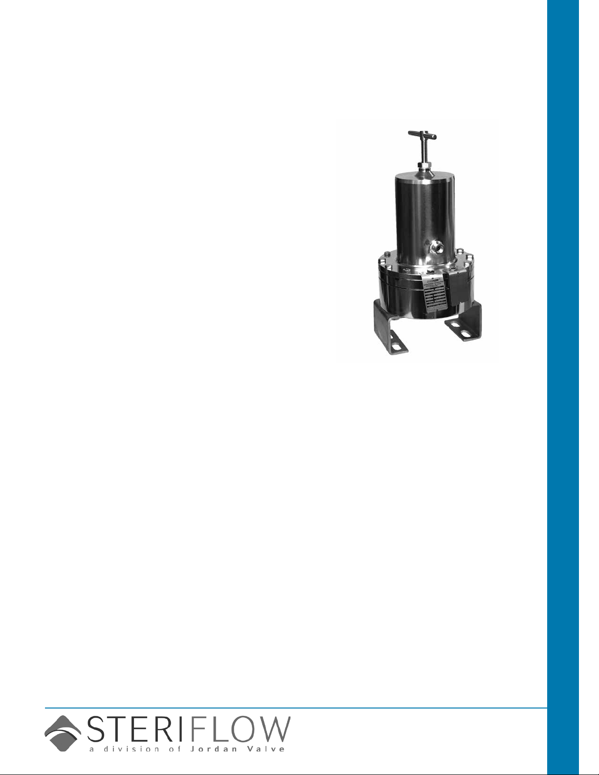
Sanitary Valves Mark 96AA Sanitary Pressure Regulators
Mark 96AA Series
Sanitary Air Augmented Pressure Regulators
The Mark 96 with air augmentation (AA) option offers
the same line sizes, Cv choices, seats, great low
droop characteristics, and stability of the standard
bolted bonnet Mark 96, but with an advantage. By
connecting an air pressure signal to the 1/4" FNPT
dome tting via an air regulator or I/P, the set point
can be changed remotely by "sending an air signal
instead of a technician".
The Mark 96AA gives users the ability to change pressure set points to any point in excess of the springs
minimum set point (2 psi on a 3/4" – 1" Mark 96, 10
psi on a 1-1/2" – 2", and 15 psi on a 3"). Users adjust
the regulator's spring to the lowest set point, or to the
lowest set pressure that the regulator will operate at
(sterilization steam pressure for example). To achieve a
higher pressure set point (CIP or WFI ush), air pressure is added to the regulator dome. To lower the set
point to it's previous value, or to the springs manual set
point, the pressure is reduced in the same manner.
"Send a signal
not a
technician"
The Mark 96AA is used in conjunction with a Steriow
self relieving I/P for control via PLC or DCS, or with a
JSRLF regulator with self relieving option (For example
- for remote control by valve mounted on wall, or panel
outside of a cleanroom.)
Features
• Reduce project CapEx. Remote regulator operation reduces the time required for steam pressure
balancing, commissioning and validation of SIP and
CIP routines.
• Complete range of products for any size or Cv
requirement. The available sizes and Cv's are the
same as the current MK96 product line.
• Mark 96AA upgrade kits available for MK96 regulators.
• With preset spring, users maintain control in the event
of power (air failure). Valve will return to manual preset.
• Minimal droop when compared with all other spring
loaded and air operated products, especially at
higher set points.
• Extended permissible operating range
when compared with all spring loaded and
air load regulators.
—
The minimum set point is equivalent
to the minimum spring rate set point (2
psi on a 3/4" – 1",
10 psi on a 1-1/2" – 2", and 15 psi on a
3" model).
No differential pressure requirements.
—
Users can adjust the set point to any
point between the minimum and maximum set point, without restriction.
Documentation
The following documentation is shipped with
each order:
• Steriow Unicert
— Certicate of Material Compliance with
Traceable Material Heat Number for
body and ferrules and MTRs
— Certicate of Compliance to FDA and
USP Class VI
— Certicate of Surface Finish
• Final Test Reports and Certicate of Origin available upon request at time of order
Steriflow by Jordan Valve
3170 Wasson Road • Cincinnati, OH 45209
513.533.5600 • 800.543.7311 • 513.871.0105 (f)
sterifl[email protected] • www.steriflowvalve.com
Page 2
Mark 96aa SerieS Sanitary air augMented PreSSure regulatorS
available Finishes
Body
• Standard: (20 Ra (SF5) mechanical nish and
electropolish) on inside wetted surfaces; machine
nish and electropolish on exterior
• Optional: 8 Ra nish on internal or external
nishes and electropolish; better than SF4 (20
Ra (SF5) mechanical nish and electropolish) on
external surfaces
Stem
• Standard: 20 Ra (SFV5) mechanical nish and
electropolish
• Optional: 8 Ra nish
Spring Housing and Handle
• Standard: electropolished, 316SST
• Optional: 8 Ra nish on external surfaces on all
sizes and electropolish (1-1/2" – 3" only); 20 Ra
(SFV5) mechanical nish and electropolish on
external surfaces
Adjusting Screw
• Standard: electropolished
• Optional: 20 Ra (SFV5) mechanical nish and
electropolish;
Note: adjusting screw is a threaded part
speciFications
Sizes: 3/4" (DN20), 1" (DN25), 1-1/2" (DN40), 2"
(DN50), 3" (DN80)
End Connections
• Quick disconnect ttings (to match Tri-Clamp®
tting)
• Tube weld ends
• DIN/ISO sanitary connections
Body Connections: Mark 96 – Bolted – Standard for
all sizes
Body & Trim Materials: 316L Stainless Steel (ASTM
SA479)
Seat Materials
• Standard hard seat – integral 316L SST seat
• Optional soft seat
– Jorlon (for Cv 1.5, 1" size and above) (FDA &
USP Class VI) for steam and hot uid service to
338°F (170°C)
– PEEK (up to 1-1/2") (FDA & USP Class VI) for
steam and hot uid service to 350° (177°C)
– Teon (for Cv 2.5, 1" size and above) to 252°F
(122°C)
[not to exceed 15 min. in a one hour period] FDA,
USP Class VI
Note: consult factory for 3/4" soft seat materials
continuous or 275°F (135°C) intermittent
speciFications (con't)
Spring Housing Materials
• CF8M cast 316 SST (3/4" – 1")
• Fabricated 316L SST (1-1/2" – 3")
Diaphragm Materials
• Jorlon (to 450°F, 232°C) – FDA, USP Class VI
• Ulta-thin Jorlon (to 400°F, 204°C), FDA, USP Class
VI (for use with 3-8 range spring only)
• EPDM/Nylon (to 275°F, 135°C) – FDA
O-Ring Material
• Teon-Encapsulated Viton (to 400°F, 204°C) –
FDA, USP Class VI
• EPDM (to 275°F, 135°C) - FDA, USP Class VI
Shutoff: ANSI Class III hard seat or Class VI soft seat
Body Pressure Temperature Rating: (dependent
upon construction)
Valve Size PSIG @ 100°F PSIG @ 450°F
3/4" & 1" 350 (24,1 bar) 250 (17,2 bar)
1-1/2" , 2", & 3" 200 (13,8 bar) 200 (13,8 bar)
Pressure on 3/4" & 1" size limited to 225 psig (15,5 bar) @
100°F and 200 psig (13,8 bar) @ 400°F if using Ultra-thin
Jorlon diaphragm.
Set Point Spring Ranges
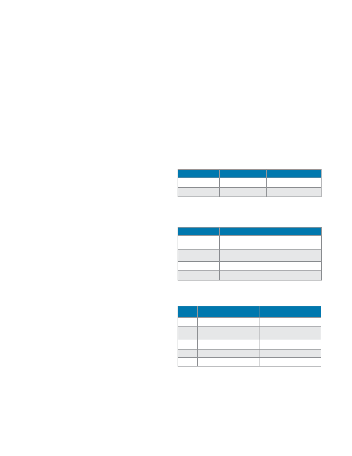
Valve Size Set Point Ranges, PSI (bar)
3/4" & 1"
1-1/2"
2" 10-25 (0,7-1,7) or 15-60 (1,0-4,1)
3" 15-25 (1,0-1,7) or 15-60 (1,0-4,1)
* Range available with elastomer or Ultra-thin Jorlon
diaphragm only. Maximum pressure drop 40 psi
Cv (Kv) Ratings:
Valve
Size
3/4"** 1.5 (1,3) 3.8 (3,27)
1"**
1-1/2" 4.5 or 10.0 (3,9 or 8,6) 6.7 (5,76); 26.3 (22,6)
2" 10.0 or 19.0 (8,6 or 16,3) 16.5 (14,2), 56.5 (48,6)
3" 10.0 or 23.0 (8,6 or 19,8) 16.5 (14,2); 67.1 (57,7)
** Cv's limited when using the 3-8 range spring
For example a 1" Cv5.5 valve with a 3-8 range spring, if the customer’s set point is P2 = 8 psi, then the actual Cv sizing should
not exceed 2.75Cv. If the customer’s intended set point is P2 =
5 psi, then the actual Cv sizing should not exceed 1.8Cv and if
their set point is P2 = 3 psi, then the actual Cv sizing should not
exceed 1.38 Cv.
-2-
Available Cvs (Kvs)
1.5, 2.5, 4.5, 5.5, 6.1
(1,3; 2,2; 3,9; 4,7; 5,3)
Set Point Sizing Limit (of rated capacity)
8 50%
5 33%
3 25%
3-8* (0,2-0,5), 5-25 (0,37-1,7), 15-50
(1,0-3,4), 40-90 (2,7-6,2)
10-25 (0,7-1,7), 15-50 (1,0-3,4) or
35-100 (2,4-6,9)
Cv for Relief Valve
Sizing
10.7 (9,2)
Page 3
Mark 96aa SerieS Sanitary air augMented PreSSure regulatorS
speciFications (con't)
Maximum Allowable Pressure Setpoint: The
total of the spring setpoint and additional air pressure cannot exceed:
• 3/4" – 1": 135 psi (9,3 bar)
• 1-1/2": 100 psi (6,9 bar)
• 2" – 3": 80 psi (5,5 bar)
Minimum Allowable Differential Pressure: No
restrictions
Minimum Allowable Setpoint: Equivalent to the
minimum spring rate set point:
• 3/4" – 1": 3 psi (0,2 bar)
• 1-1/2" – 2": 10 psi (0,69 bar)
3": 15 psi (1,03 bar)
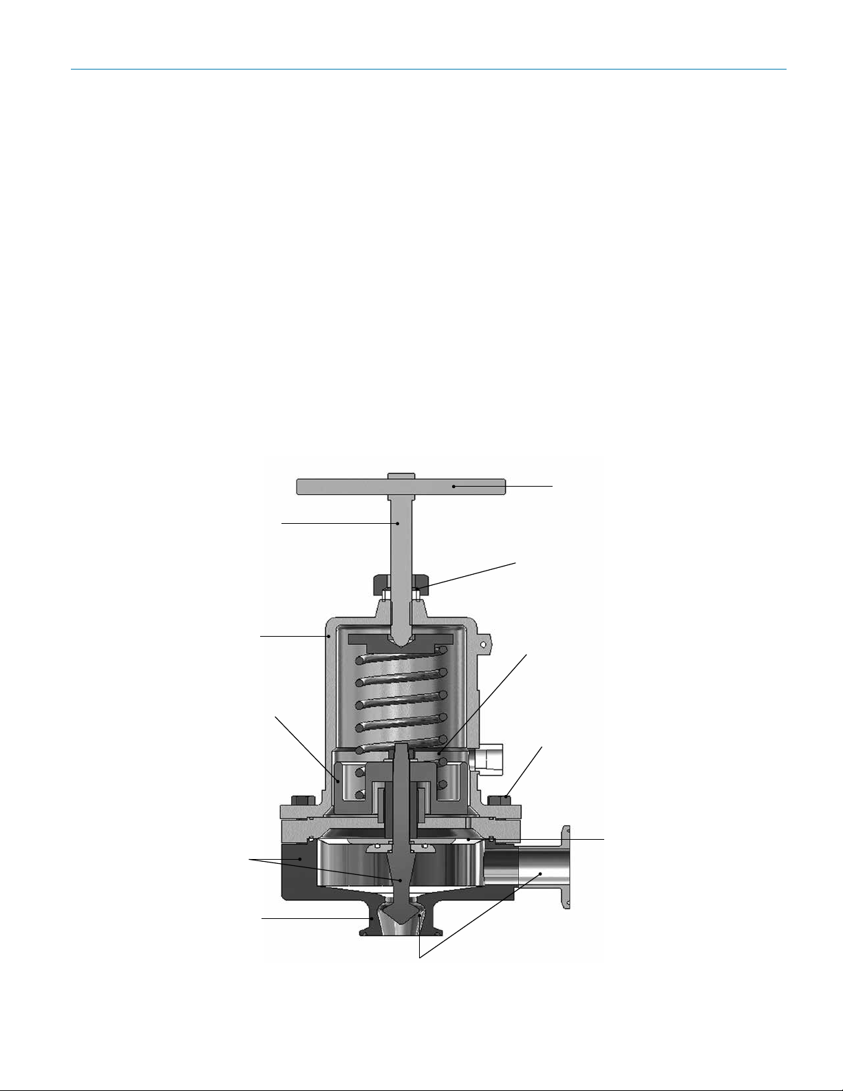
Features & beneFits
316 adjusting screw
Surface Finish: Refer to MK96 data sheet
Minimum Allowable Differential Pressure: No
restrictions
Note: Steriow does not recommend using metal
seated trim on any service where the ow will be
deadheaded downstream of the pressure reducing
regulator. Use an appropriate Teon, Jorlon, or Peek
soft seat for the trim instead.
316 T-handle for easy
handling and minimum
setpoint adjustment
316 Stainless Steel
spring housing
Guiding above diaphragm
area, not in seat/orice, to
eliminate metal-to-metal
particulate generation
100% barstock
body and trim
No guiding in the
wetted area
Teon Seal Nut
With an airload the
balanced spring and
bushing assembly provides
excellent stability and
minimal droop
Bolted bonnet for increased
safety and pressure/
temperature rating
Lifetime
guarantee on
Jorlon
diaphragm
Self-draining design with 20 Ra (SFV5)
mechanical and electropolished internals (in
this orientation)
-3-
Page 4
Mark 96aa SerieS Sanitary air augMented PreSSure regulatorS
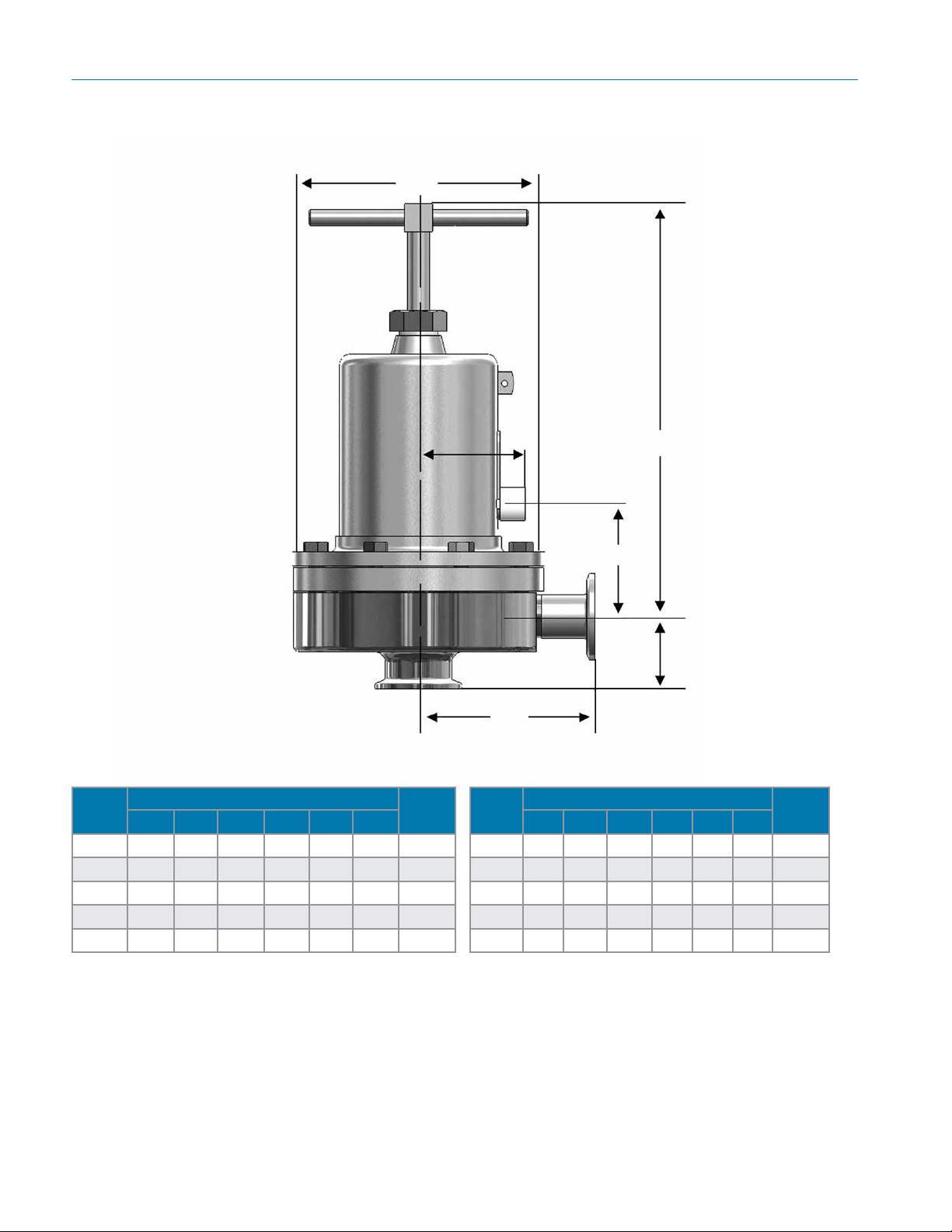
Dimensions
ØD
Inlet
Valve
Size
A B C D E F
Dimensions (inches)
Weight
Lbs
3/4" 3.29 8.00 1.50 5.70 2.44 2.44 18
1" 4.00 8.00 1.64 5.70 2.44 2.57 20
1-1/2" 4.21 10.5 2.53 7.25 2.82 3.49 40
2" 5.34 17.5 2.96 9.50 3.83 4.89 90
3" 5.34 18.0 3.46 9.50 3.83 5.39 98
E
B
F
Outlet
C
A
Valve
Size
A B C D E F
Dimensions (mm)
Weight
DN20 84 203 38,1 145 62 62 8,1
DN25 102 203 41,7 145 62 65 9,1
DN40 107 267 64,3 184 72 89 18/13
DN50 136 445 75,2 241 97 124 41/30
DN80 136 457 87,9 241 97 137 44,4
Kgs
-4-
Page 5
Mark 96aa SerieS Sanitary air augMented PreSSure regulatorS
sample speciFication
Stainless steel sanitary pressure regulator shall be made from ASME-SA479 barstock material,
which includes body and all wetted metal parts. Regulator shall utilize FDA approved, USP Class
VI certied Jorlon diaphragm. Regulator shall be fully and remotely adjustable with the addition of a
pneumatic air signal, to any set point above the minimum spring set point up to a maximum of 135
psi for sizes 1" and below; 80 psi for 1-1/2" and above. In the event of air system failure, valve shall
be manually adjustable. Guiding of valve stem/plug shall be outside of the wetted process areas of
valve internals, above diaphragm. Regulator shall be free of threads within wetted, process areas
and shall be self draining when installed with inlet vertical and below valve assembly.
sizing anD selection
In order to nd out the actual Cv and/or ow rates for your application, complete the following:
1. Select the appropriate line size, required nominal Cv, and set point spring for your application from
the charts on page 2, or from the ordering grid below.
2. Input that data, along with the installation inlet pressure, desired outlet pressure set point, and other
required data into the Steriow SFCV sizing program. If you do not have a copy of the sizing program,
call your local Steriow representative or request a copy by email to steri[email protected].
3. If the actual Cv, or ow rate (if solving for ow rate), are not sufcient for your application, then select
and input a more appropriate valve Cv for that line size until you get an actual Cv that will work in
your application. Note: If the actual Cv generated by the program is still not appropriate, you may be
required to input a different valve line size, in order to obtain the correct Cv. Note, never select an
automated valve by line size only.
Note: if ordering a Retrot Kit for an existing Mark 96, you must provide the serial number of the
Mark 96 with your RFQ or order.
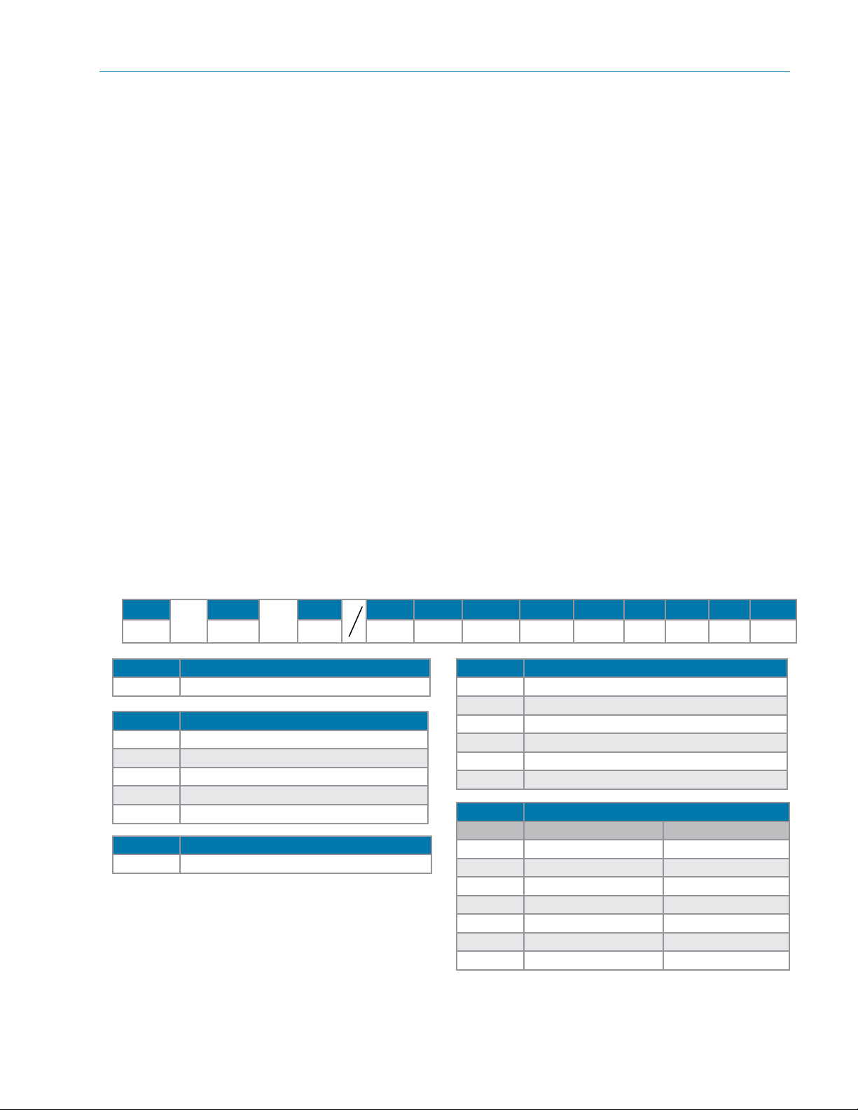
orDering schematic For mark 96aa
1
—
1 Model
96AA Standard
2 Size
075 3/4"
100 1"
150 1-1/2"
200 2"
300 3"
3 Body Material
6L 316L
2
3
—
4 5 6 7 8 9 10 11 12
1
4 Body Finish
A 20Ra (SFV5) Interior/63RMS Exterior (Std)
B 20Ra (SFV5) Interior/20Ra Exterior
C 8Ra Interior/63RMS Exterior
D 20Ra (SFV5) Interior/8Ra Exterior
E 8Ra Interior/8Ra Exterior
F 8Ra Interior/20Ra Exterior
5 Body Cv (Kv) See chart on page 2
Cv Kv
A 1.5 (3/4" & 1") 1,3
D 2.5 (1" only) 2,2
H 4.5 (1" & 1-1/2") 3,9
K 5.5 & 6.1 (1" only) 4,7 & 5,3
M 10.0 (1-1/2" – 3") 8,6
N 19.0 (2" only) 16,3
P 23.0 (3" only) 19,8
Consult factory for parts to retrot a MK96 into a MK96AA. Retrot kits may not be available with some MK96
project valves and valve models older than 2002. The valve serial number will identify your MK96's bill of material and is
required for proper retrot selection.
-5-
Page 6
Mark 96aa SerieS Sanitary air augMented PreSSure regulatorS
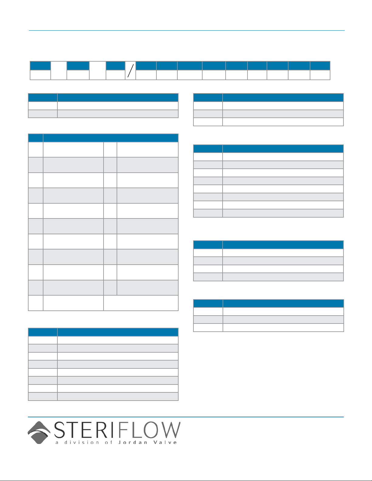
orDering schematic For mark 96aa
96AA/0414/AB
1
—
2
—
3
4 5 6 7 8 9 10 11 12
1
6 Trim Finish
A 20Ra (Standard)
B 8Ra
7 Trim – Cv (Kv) & Seat
1.5 (1,3) Hard Seat
A
2
B
C
D
H
J
K
L
M
N
3/4" – 1"
1.5 (1,3) Jorlon Seat
1"
2.5 (2,2) Hard Seat
1" only
2.5 (2,2) Teon Seat
1" only
2.5 (2,2) Jorlon Seat
1" only
4.5 (3,9) Hard Seat
1" & 1-1/2"
4.5 (3,9) Teon Seat
1" & 1-1/2"
4.5 (3,9) Jorlon Seat
1" & 1-1/2"
5.5 (4,7) Hard Seat
1" only
5.5 (4,7) Teon Seat
1" only
5.5 (4,7) Jorlon Seat
1" only
6.1 (5,3) Hard Seat
7
P
Q
R
S
19 (16,3) Teon Seat
T
19 (16,3) Jorlon Seat
U
V
23 (19,8) Teon Seat
W
23 (19,8) Jorlon Seat
X
1" only
10 (8,6) Hard Seat
1-1/2" – 3"
10 (8,6) Teon Seat
1-1/2" – 3"
10 (8,6) Jorlon Seat
1-1/2" – 3"
19 (16,3) Hard Seat
2" only
2" only
2" only
23 (19,8) Hard Seat
3" only
3" only
3" only
8 O-Ring/Diaphragm
TY Teon Encaps. Viton/Jorlon Diaphragm
JE EPDM/Jorlon
JS Silicone/Jorlon
JV Viton/Jorlon
JY TFE/Silicone/Jorlon (1-1/2" - 3")
JK Kalrez/Jorlon
EE EPDM/EPDM Diaphragm
ZZ Non-Standard
9 Adjusting Screw Finish (Except Threads)
A Electro-polished (Standard)
B 20Ra (SFV5)
C 8Ra
10 Range PSI (Bar) see chart on page 2
A 3 - 8 (0,1 - 0,6)* 3/4" – 1"
C 5 - 25 (0,3 - 1,7) 3/4" – 1"
E 10 - 25 (0,7 - 1,7) 1-1/2" – 2"
P 15 - 25 (1,0 - 1,7) 3" only
H 15 - 50 (1,0 - 3,4) 3/4" – 1-1/2"
J 15 - 60 (1,0 - 4,1) 2" & 3"
M 35 - 100 (2,4 - 6,9) 1-1/2" only
R 40 - 90 (2,8 - 6,2) 3/4" & 1"
* Must use EPDM or Ultra-thin Jorlon diaphragm
11 Diaphragm
EP EPDM (all exterior)
JL Jorlon (all exterior)
UJ Ultra-thin Jorlon (all exterior)
ZZ Non-Standard
12 Actuator Finish/Type
AA Standard
BA 20Ra (SFV5) exterior
CA 8Ra exterior
Steriflow, a division of Jordan Valve
3170 Wasson Road • Cincinnati, OH 45209
513.533.5600 • 800.543.7311 • 513.871.0105 (f)
sterifl[email protected] • www.steriflowvalve.com
Steriflow Valve reserves the right to make revisions to its product, specifications, literature and related information without notice. Please visit our
website at www.steriflowvalve.com for the latest information on our products.
 Loading...