

Page 1
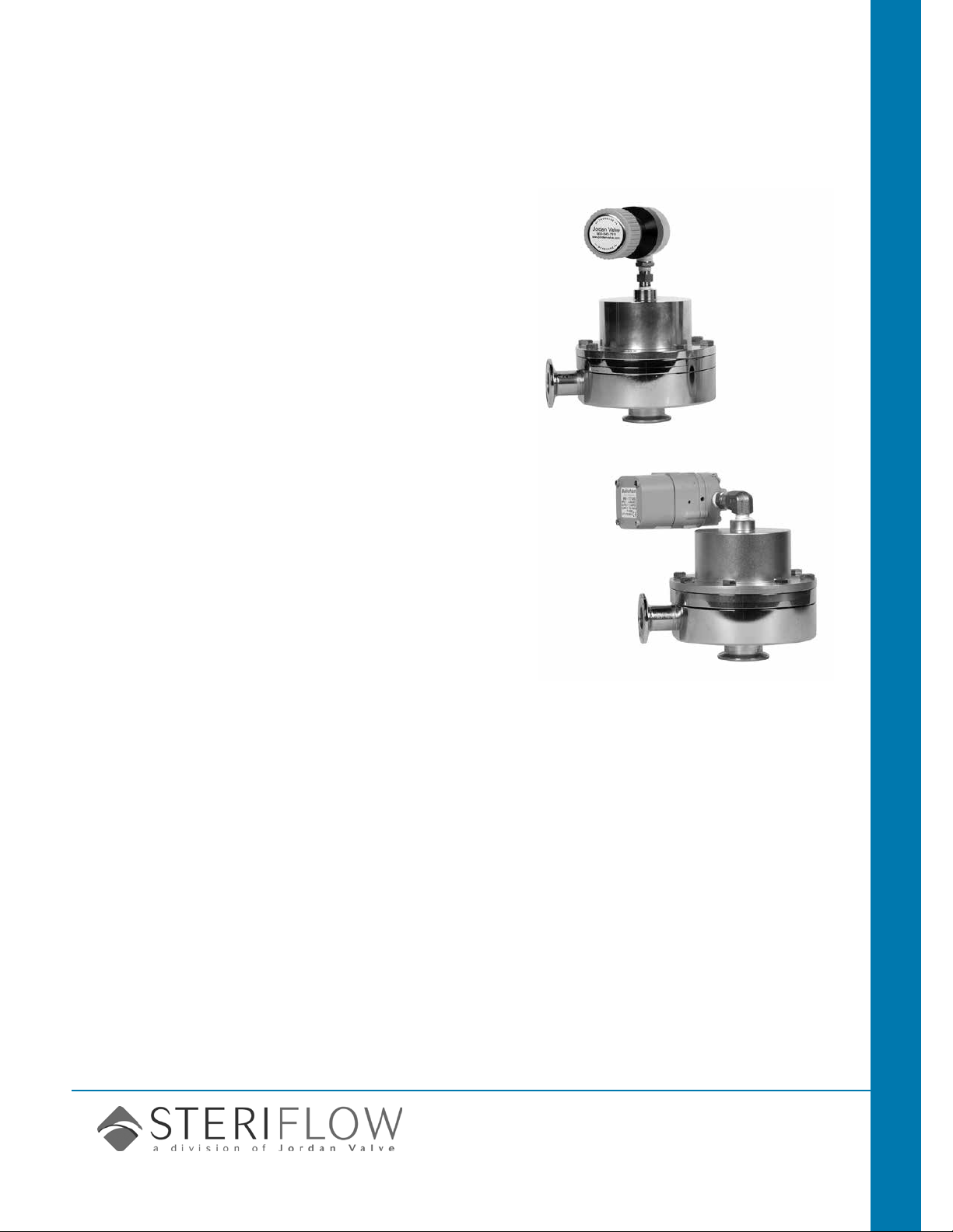
Mark 96A Series
Sanitary Air Loaded Pressure Regulators
The Mark 96A is an air loaded sanitary pressure
reducing valve designed to permit the user to
change setpoints remotely via a cabinet or panel
mounted air regulator, or through a distributed
control system using an I-P transducer.
The Mark 96A is an ideal choice for automating
the SIP/CIP process when the operating setpoint
for each operation is different. With remote setpoint change capability, the valve pressure can be
changed by remotely adjusting the air pressure
loaded to the dome to the unique needs of the
current operation.
CRN Registration Number Available
Sanitary Valves Mark 96A Sanitary Pressure Regulators
Features
• CRN Registration Number Available
• Air-loaded design significantly reduces size
and weight and can minimize offset in some
applications
• Optimized diaphragm material, surface area and
support system for unsurpassed performance and
life
• Valve sub-assembly same as time-tested MK96
design
• Permits automated CIP/SIP
• Available with extended range I-P transducer or a
SST gas regulator
Documentation
The following documentation is shipped with each
order:
• Steriow Unicert
— Traceable Material Heat Number for body and
ferrules
— Certicate of Compliance to FDA and USP
Class VI
Certicate of Surface Finish
• Final Test Reports and Certicate of Origin avail-
able upon request at time of order
applications
A wide variety of applications exist for the
MK96A in the pharmaceutical, biotech, healthcare, food & beverage and other industries
including:
• Clean Steam
• WFI
• Process Gases
• Clean Filtered Air
• CIP Chemicals
• Food/Beverage Product
• Pharmaceutical Product
• Biochemicals
Steriflow by Jordan Valve
3170 Wasson Road • Cincinnati, OH 45209
513.533.5600 • 800.543.7311 • 513.871.0105 (f)
sterifl[email protected] • www.steriflowvalve.com
Page 2
Mark 96a Sanitary air-Loaded PreSSure reguLator
speciFications
Sizes: 1" (DN25), 1-1/2" (DN40), 2" (DN50)
Material: 316L Barstock body and trim
End Connections: ASME Tri-Clamp, butt weld,
others consult factory
Cv:
• 4.5 (1")
• 10 (1-1/2")
• 19 (2")
®
Seat Material: Teflon
(FDA, USP CL 6 approved),
PEEK (FDA, USP CL 6 approved) optional
Shutoff: ANSI Class VI
Actuator Housing: Air-loaded, clear coat anodized
aluminum housing (standard) or electropolished
316 Stainless Steel (optional)
O-Ring Material: FDA, USP CL 6 approved Teflon-
Encapsulated Viton
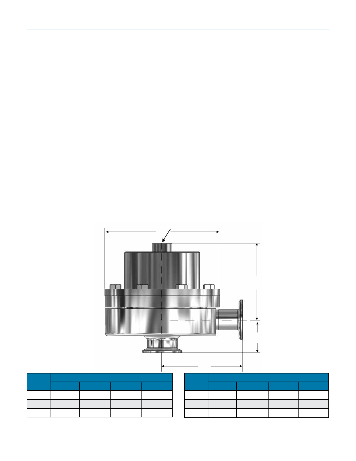
Dimensions
D
Diaphragm Material: Jorlon (FDA, USP CL 6
approved)
Maximum Setpoint: 100 psi (6,9 bar) – see
operational chart
Maximum Operating Pressure @ Maximum
Temperature: 200 psi @ 300°F (13,8 bar @ 149°C)
Maximum Pressure Drop: up to 100 psi (6,9 bar) –
see operational chart
Maximum Air Supply Pressure: 110 psi
Weight:
• 1" – 12.0 lbs (5,4 kgs) – Aluminum
• 1" – 12.5 lbs (5,7 kgs) – Stainless Steel
• 1-1/2" – 31.0 lbs (14,1 kgs) – Aluminum
• 1-1/2" – 34 lbs (15,4 kgs) – Stainless Steel
• 2" – 69 lbs (31,3 kgs) – Aluminum
• 2" – 72 lbs (32,7 kgs) – Stainless Steel
1/4" FNPT
Valve
Size
1" 4.00 3.80 1.64 5.75
1-1/2" 4.21 6.40 2.53 7.22
2" 5.34 6.75 2.96 9.50
A B C D
Dimensions (inches)
B
C
A
Valve
Size
DN25 101,6 96,5 41,7 146,1
DN40 106,9 162,6 64,3 183,4
DN50 135,6 171,5 75,2 241,3
Based on US tri-clamp ends. Consult factory for DIN and ISO tri-clamp
end dimensions
-2-
A B C D
Dimensions (mm)
Page 3
Mark 96a Sanitary air-Loaded PreSSure reguLator
available Finishes
Body
• Standard: 20 Ra µin (0,5 Ra µm) (ASME BPE 2009 SF5) mechanical nish and electropolish on inside wetted surfaces; machine nish and electropolish on exterior.
• Optional: 20 Ra µin (0,5 Ra µm) SF5 mechanical nish and electropolish on external surfaces; 8 Ra µin (0,2
Ra µm) nish on internal or external nishes and electropolish (Better than SF4)
Bonnet Dome
• Standard: 20 Ra µin (0,5 Ra µm) machine nished and electropolished 316SST.
If aluminum, not electropolished
• Optional: 20 Ra µin (0,5 Ra µm) mechanical nish and electropolish on external surfaces (SF5). 8 Ra µin (0,2
Ra µm) nish on external surfaces on all sizes and electropolish. (Better than SF4).
If aluminum, not electropolished
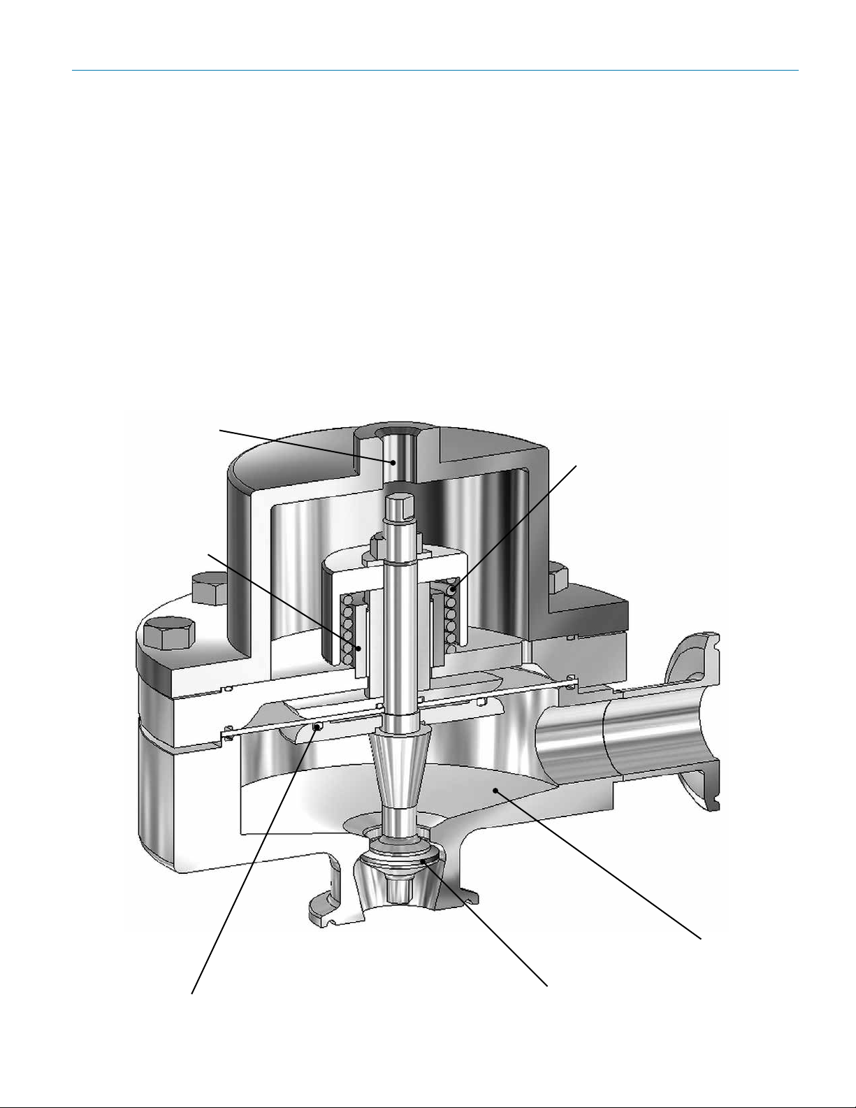
mark 96a series Cut-a-Way
Air loaded for remote
setpoint adjustments
Guiding above process
area eliminates
particulate generation
Light bias spring for
stable operation at low
flow
Optimized diaphragm
area for minimal offset
and extended life
No hold up, fully
drainable in this
orientation
Soft sealing for ANSI
Class VI shutoff
-3-
Page 4
200 (13,8)
175 (12,1)
150 (10,3)
Mark 96a Sanitary air-Loaded PreSSure reguLator
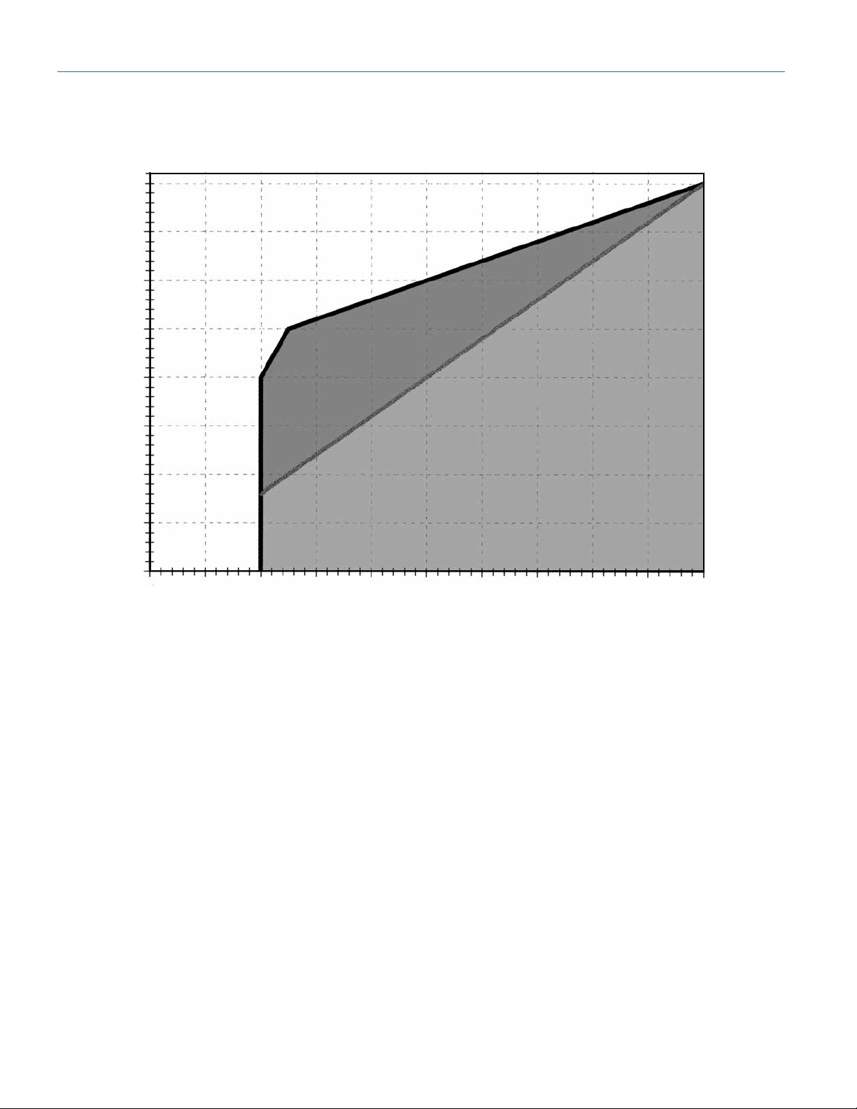
maximum inlet Pressure vs setPoint
125 (8,6)
Allowable Area
of Operation
100 (6,9)
Optimal Area of Operation
75 (5,2)
Maximum Inlet psi (bar)
50 (3,4)
25 (1,7)
0
0 10
(0,7)
20
(1,4)
30
(2,1)
Outlet Pressure Setpoint (psi (bar)
40
(2,8)
50
(3,4)
60
(4,1)
70
(4,8)
80
(5,5)
90
(6,2)
100
(6,9)
Determining Allowable & Optimal Setpoint
Reading the graph: To determine allowable setpoint select your inlet pressure from the Y-axis on the
above graph. Outlet pressure setpoint should be equal to or greater than the value on the X-axis
where the inlet pressure and heavy diagonal line intersect. In other words, the differential pressure
(between inlet pressure and outlet pressure setpoint) must be less than or equal to 100 psi. In addition the minimum outlet pressure setpoint is 20 psig.
For optimal results (minimum offset, more stability) the ratio of inlet pressure to the outlet pressure
setpoint (differential pressure) should be 2:1 or less, and never greater than 100 psig. For example,
if the inlet pressure is 150 psi, the allowable outlet pressure setpoint would be 50 psi or above.
However, the optimal outlet pressure setpoint (greater stability and less droop) is 75 psig or greater.
Note:
1. Valve actuator loading pressure (supply pressure) must be at least 3 psi above the desired
outlet pressure setpoint. This is needed to overcome the return spring bias.
Installation Notes
• As with all regulators and control valves, optimal flow performance can only be achieved with
a non-turbulent flow profile. The Mark 96A should be installed with 3 feet of straight pipe on either
side of the valve.
• A pressure gauge, or transmitter reading downstream of the Mark 96A should be used to make
the final setpoint adjustment.
-4-
Page 5
Mark 96a Sanitary air-Loaded PreSSure reguLator
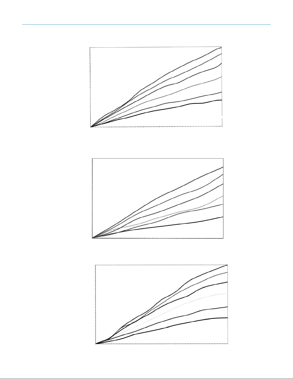
% stroke vs FloW (1" mk96a – Jorlon DiaPhragm – 4.5 Cv)
40
35
30
75 psid
60 psid
45 psid
25
30 psid
20
15 psid
15
Flow (gpm)
7.5 psid
10
5
0
0% 10% 20% 30% 40% 50% 60% 70% 80% 90% 100%
% Stroke
% stroke vs FloW (1-1/2" mk96a – Jorlon DiaPhragm – 10 Cv)
100
90
80
70
60
50
40
Flow (gpm)
30
20
10
75 psid
60 psid
45 psid
30 psid
15 psid
7.5 psid
0
0% 10% 20% 30% 40% 50% 60% 70% 80% 90% 100%
% Stroke
troke vs FloW (1-1/2" mk96a – Jorlon DiaPhragm – 19 Cv)
% s
200
75 psid
180
160
140
120
100
80
Flow (gpm)
60
40
20
0
0% 10% 20% 30% 40% 50% 60% 70% 80% 90% 100%
% Stroke
-5-
60 psid
45 psid
30 psid
15 psid
7.5 psid
Page 6
Mark 96a Sanitary air-Loaded PreSSure reguLator
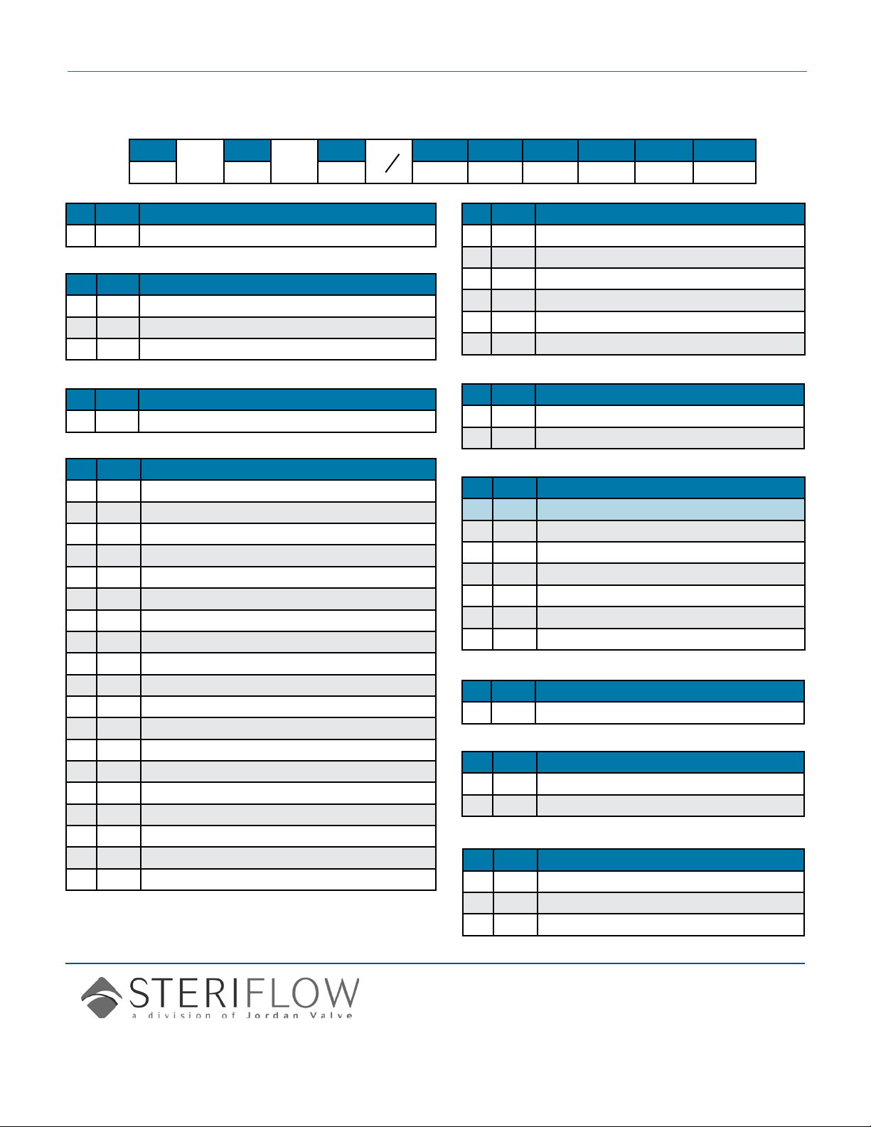
orDer sChematiC
96A/0713
1
—
2
—
3 4 5 6 7 8 9
1 Model
96A Standard
2 Size
100 1" (DN25)
150 1-1/2" (DN40)
200 2" (DN50)
3 Material
6L 316L Stainless Steel
4 Body & Cv
AH 20ra Interior/63rms Exterior (Standard); 4.5Cv
BH 20rA Interior/20ra Exterior; 4.5Cv
CH 8rA Interior/63rms Exterior; 4.5Cv
DH 20rA Interior/8ra Exterior; 4.5Cv
EH 8rA Interior/8ra Exterior; 4.5Cv
FH 8rA Interior/20ra Exterior; 4.5Cv
AM 20rA Interior/63rms Exterior (Standard); 10Cv
BM 20rA Interior/20ra Exterior; 10Cv
CM 8rA Interior/63rms Exterior; 10Cv
DM 20rA Interior/8ra Exterior; 10Cv
EM 8rA Interior/8ra Exterior; 10Cv
FM 8rA Interior/20ra Exterior; 10Cv
AN 20rA Interior/63rms Exterior (Standard); 19Cv
BN 20rA Interior/20ra Exterior; 19Cv
CN 8rA Interior/63rms Exterior; 19Cv
DN 20rA Interior/8ra Exterior; 19Cv
EN 8rA Interior/8ra Exterior; 19Cv
FN 8rA Interior/20ra Exterior; 19Cv
ZZ Non-Standard
5 Trim; Cv & Seat
AJ 20 rA (Standard); Cv 4.5 Teflon Seats
BJ 8 rA; Cv 4.5 Teflon Seats
AQ 20 rA (Standard); Cv 10 Teflon Seats
BQ 8 rA; Cv 10 Teflon Seats
AT 20 rA (Standard); Cv 19 Teflon Seats
BT 8 rA; Cv 19 Teflon Seats
6 O-Ring
TY Teflon Encaps. Viton / Jorlon Diaphragm
ZZ Non-Standard
7 I/P or Loader Range
Type of Loader Max Load (psi)
00 None
AP 60 psi output I/P
AH 120 psi output I/P
BA J Series 25 psi output
BC J Series 50 psi output
BE J Series 100 psi output
8 Diaphragm
JL Jorlon
9 Actuator
AA Anodized Aluminum
BA 316 Stainless Steel
10 Accessories
SC Clean for oil free
XC 02 Clean
0F PED Certification
Steriflow, a division of Jordan Valve
3170 Wasson Road • Cincinnati, OH 45209
513.533.5600 • 800.543.7311 • 513.871.0105 (f)
sterifl[email protected] • www.steriflowvalve.com
Steriflow Valve reserves the right to make revisions to its product, specifications, literature and related information without notice. Please visit our
website at www.steriflowvalve.com for the latest information on our products.
 Loading...