

Page 1
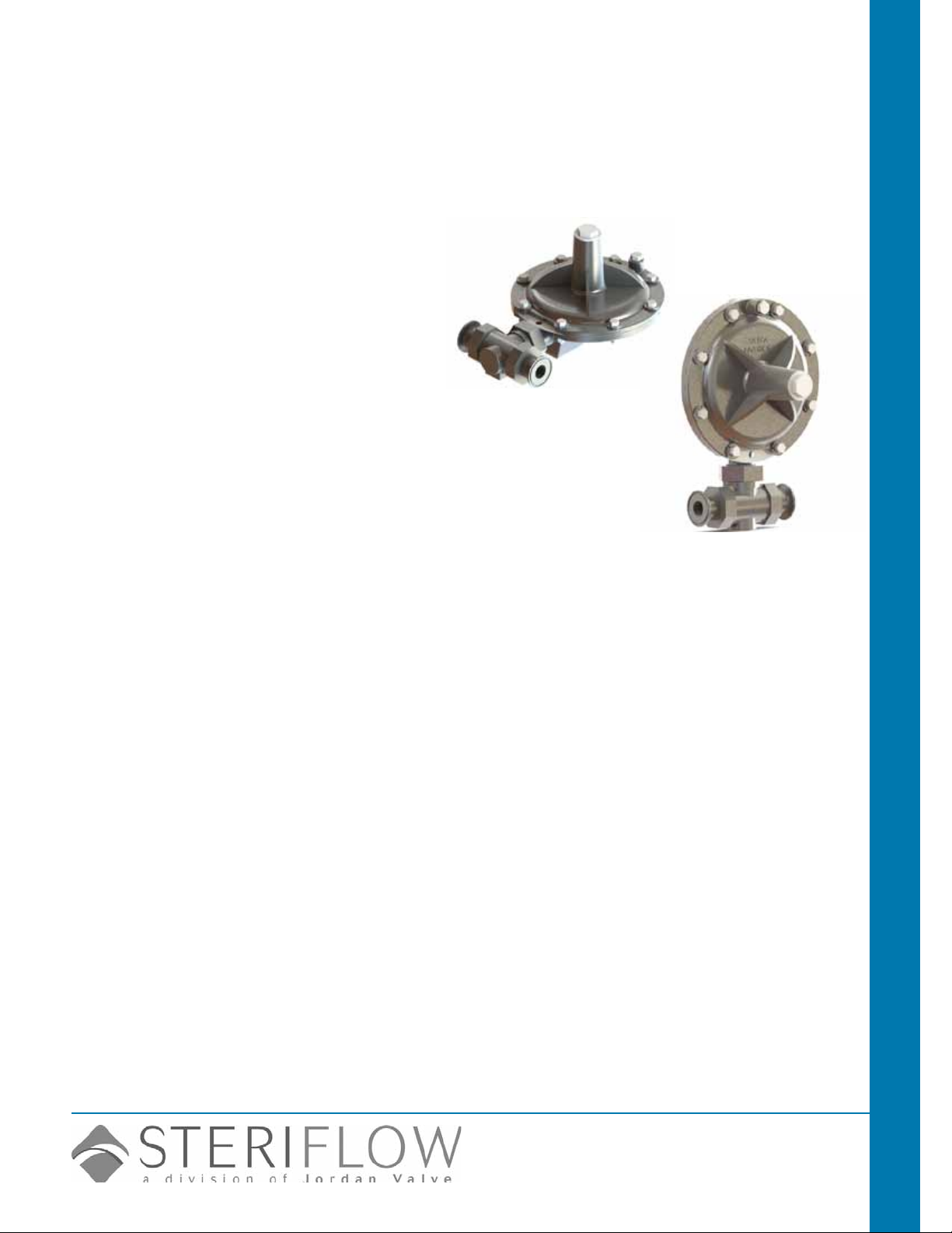
Mark 968 Series
Sanitary Gas Regulators sizes 3/4" - 2" for biopharm, pharma, food &
beverage low pressure Clean Dry Gas/Air blanketing and inline
pressure regulation
The Mark 968 Sanitary Gas Regulator is the ideal valve
for low pressure gas regulation in pharmaceutical and
food & beverage applications. The self-contained low
pressure gas regulator is for use on tank blanketing and
other very low critical pressure air and gas applications.
The Mark 968 is normally open. Increases in the outlet
pressure are sensed through the aspirator causing the
large elastomer diaphragm to rise, which moves the
plug toward the seat. As outlet pressure decreases, the
diaphragm moves down and moves the plug away from
the seat to increase ow. The lever, which connects the
stem to the diaphragm, amplies diaphragm forces for
tighter shutoff (only available on sizes 3/4" and 1").
Gas Regulators Mark 968 Sanitary Gas Regulator
The large diaphragm and lever actuation allows the
Mark 968 to act with higher sensitivity compared to
smaller diaphragm pressure regulators. High sensitivity
is important, as the Mark 968 often works with very low
pressure (down to 1" w.c. or 2,5 mbar). This special
actuation improves the accuracy and shutoff of the valve
- two important benets in this style of regulator.
Together, the SST construction, FDA-approved seals
and the tri-clamp connections make this valve well
suited for sterile gas applications and environments.
Features
• Inlet pressures up to 150 psi (10 bar)
• Robust design — emergency outlet pressure may
reach 100% of inlet pressure without damaging
valve
• 360° body orientation — valve can be installed in
any position, and can be easily repositioned while
in-line
• Easy maintenance — seat and plug can be in-
spected without removing body from the line
• Completely self-operated — no external power
source required
• Tight shutoff — soft elastomer plug provides ANSI
Class VI shutoff
• 316/316L SST body/trim and tri-clamp, quick dis-
connect clamp connection
• FDA-approved seals and diaphragms
• Optional electropolishing available
speciFications
Line Sizes: 3/4" (DN20) & 1" (DN25)
End Connections
• Clamped — ISO/DIN or Tri Clamp
• Flanged — 150#, 300#, PN25/40 & sterile anges
Materials
• Body & Housing: SA351 Gr. CF8M 316SS, OR
CF3M 316L
• Seat: ASTM A479 316/316L
• Plug: ASTM A479 316L and FDA-approved Viton
• Diaphragm: Viton (FDA)
• Aspirator Tube: FDA USP Class VI Teon
Service: Air or gas
Shutoff: ANSI Class VI
Temperature Range: -20°F (-29°C) to 200°F (93°C)
Maximum Inlet Pressure: 150 psi (10 bar)
Reduced Pressure Control Range:
• 1.0 to 2.5 inches w.c. (2,5 to 6,2 mbar)
• 2.0 to 5.5 inches w.c. (5,0 to 13,7 mbar)
• 4.0 to 10.0 inches w.c. (10,0 to 24,9 mbar)
• 5.0 to 30.0 inches w.c. (12,4 to 74,7 mbar)
• 0.5 to 1.75 psig (0,03 to 0,12 bar)
• 1.0 to 3.5 psig (0,07 to 0,24 bar)
Orice Sizes (Interchangeable): 1/8" (3mm), 3/16"
(5mm), 1/4" (6mm), 5/16" (8mm), 3/8" (10mm), 7/16"
(11mm), 1/2" (13mm), 9/16" (14mm)
Steriflow by Jordan Valve
3170 Wasson Road • Cincinnati, OH 45209
513.533.5600 • 800.543.7311 • 513.871.0105 (f)
steri[email protected] • www.steriowvalve.com
Page 2
Mark 968 Sanitary GaS reGulator
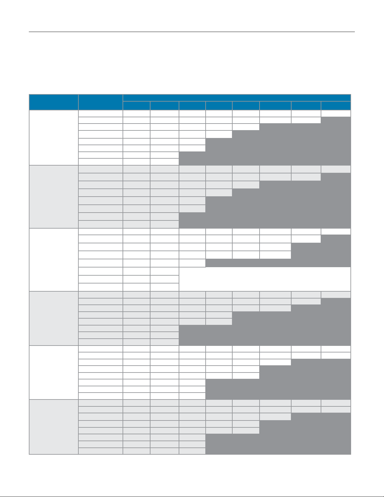
3/4" n2 Max Flow capacity: scFH
To select the orifice size for your valve you need to know P1 (inlet pressure). P2 (outlet pressure set point), and maximum flow in SCFH.
1. Select the row that best represents your outlet Set Pressure (P2)
2. Select the sub-row that is representative of your Inlet Pressure (P1)
3. Find the Flow rate in that sub-row that encompasses your maximum flow. Look at the orifice column heading to determine your specific orifice size.
Set Pressure Inlet (psi)
5 201 374 430 261 477 888 1043 1169
10 213 402 456 580 506 784 943
2" H20
(1-2.5" H20)
1" H20 Droop
2" H20 Boost*
3" H20
(2-5" H20)
1" H20 Droop
2" H20 Boost*
7" H20
(4-10" H20)
1" H20 Droop
2" H20 Boost*
28" H20
(5-30" H20)
5-1/2" H20 Droop
1.25 psi
(0.5 - 1.75 psi)
0.2 psi Droop
3 psi
(1 - 3 .5 psi)
0.3 psi Droop
* Boost refers to a small rise in outlet pressure set point that can occur, and is characteristic of, this type of regulator when flow nears the valve's maximum capacity. To understand this
phenomenon and to determine your maximum flow requirements, see API 2000
20 222 392 475 619 361
40 299 465 639 764
60 665 897 1161
80 816 873 1139
100 598 640
150 770 825
5 239 373 503 560 613 886 1163 1195
10 231 402 566 580 591 783 977
20 211 392 570 619 295
40 277 465 649 764
60 597 897 1194
80 753 873 976
100 675 776
150 880 825
5 220 295 372 409 441 619 799 661
10 277 427 578 527 476 732 982
20 258 462 661 893 1118 1154
35 276 592 897 967 1035 1294
75 525 980 1426
90 727 1364
100 813 1503
150 1040 1926
5 302 454 604 722 839 941 1040 1074
10 337 533 723 981 1239 1378 1514
30 283 816 1335 1666 1982 2154
45 617 1373 2058 2487
60 817 1866 2906 2899
75 820 1812
100 840 1867
150 1089 2421
5 180 272 439 395 526 465 658 921
10 235 333 522 535 783 665 913 848
30 279 469 824 785 1014 1141
45 354 561 886 856 1033
60 418 669 1003 937 1087
75 427 762 1152
100 543 949 1402
150 715 1266 1816
5 145 217 289 315 338 371 402 675
10 209 312 418 502 592 625 661 731
30 226 468 701 783 859 1136
45 354 561 812 856 856
60 415 669 922 937 945
75 427 762 1059
100 503 949 1408
150 660 1266 1816
1/8" 3/16" 1/4" 5/16" 3/8" 7/16" 1/2" 9/16"
-2-
Orifice Size
Flow in this area is outside the operating
parameters of the valve
Flow in this area is outside the operating
parameters of the valve
Flow in this area is
outside the operating
parameters of the valve
Flow in this area is outside the operating
parameters of the valve
Flow in this area is outside the operating
parameters of the valve
Flow in this area is outside the operating
parameters of the valve
Page 3
Mark 968 Sanitary GaS reGulator
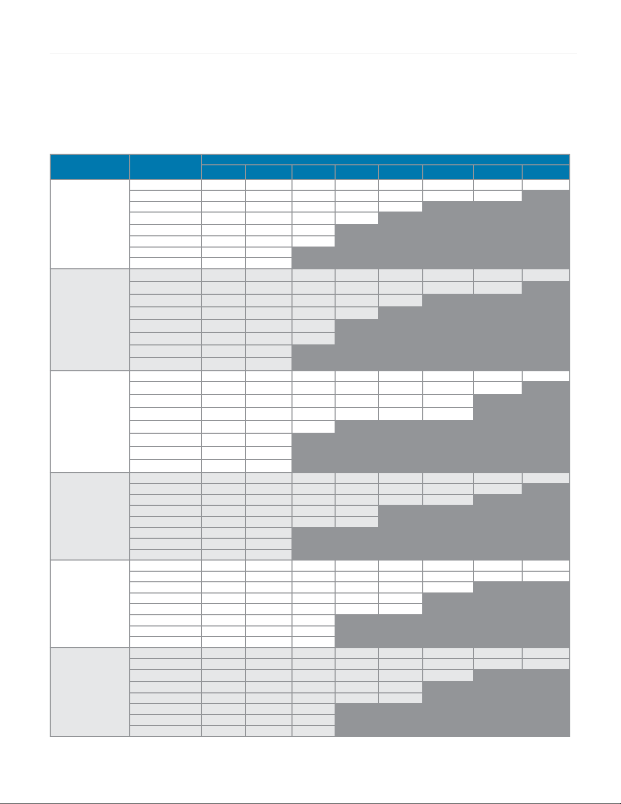
3/4" n2 Max Flow capacity: nM3/H
To select the orifice size for your valve you need to know P1 (inlet pressure). P2 (outlet pressure set point), and maximum flow in NM3/H.
1. Select the row that best represents your outlet Set Pressure (P2)
2. Select the sub-row that is representative of your Inlet Pressure (P1)
3. Find the Flow rate in that sub-row that encompasses your maximum flow. Look at the orifice column heading to determine your specific orifice size.
Set Pressure Inlet (bar)
0.345 5.7 10.6 12.2 7.4 13.5 25.1 29.5 33.1
0.689 6.0 11.4 12.9 16.4 14.3 22.2 26.7
2" H20
(1-2.5" H20)
1" H20 Droop
2" H20 Boost*
3" H20
(2-5" H20)
1" H20 Droop
2" H20 Boost*
7" H20
(4-10" H20)
1" H20 Droop
2" H20 Boost*
28" H20
(5-30" H20)
5-1/2" H20 Droop
0,09 bar
(0.03 - 0,12 bar)
0,01 bar Droop
0,21 bar
(0,07 - 0,24 bar)
0,02 bar Droop
* Boost refers to a small rise in outlet pressure set point that can occur, and is characteristic of, this type of regulator when flow nears the valve's maximum capacity. To understand this
phenomenon and to determine your maximum flow requirements, see API 2000
1.38 6.3 11.1 13.4 17.5 10.2
2.76 8.5 13.2 18.1 21.6
4.14 18.8 25.4 32.9
5.52 23.1 24.7 32.2
6.89 16.9 18.1
10.3 21.8 23.3
0.345 6.8 10.6 14.2 15.8 17.3 25.1 32.9 33.8
0.689 6.5 11.4 16.0 16.4 16.7 22.2 27.6
1.38 6.0 11.1 16.1 17.5 8.3
2.76 7.8 13.2 18.4 21.6
4.14 16.9 25.4 33.8
5.52 21.3 24.7 27.6
6.89 19.1 22.0
10.3 24.9 23.3
0.345 6.2 8.3 10.5 11.6 12.5 17.5 22.6 18.7
0.689 7.8 12.1 16.4 14.9 13.5 20.7 27.8
1.38 7.3 13.1 18.7 25.3 31.6 32.7
2.41 7.8 16.8 25.4 27.4 29.3 36.6
5.17 14.9 27.7 40.4
6.21 20.6 38.6
10.3 29.4 54.5
0.345 8.5 12.8 17.1 20.4 23.7 26.6 29.4 30.4
0.689 9.5 15.1 20.5 27.8 35.1 39.0 42.8
2.07 8.0 23.1 37.8 47.1 56.1 61.0
3.10 17.5 38.9 58.2 70.4
4.14 23.1 52.8 82.2 82.0
5.17 23.2 51.3
6.89 23.7 52.8
10.3 30.8 68.5
0.345 5.1 7.7 12.4 11.2 14.9 13.2 18.6 26.1
0.689 6.7 9.4 14.8 15.1 22.2 18.8 25.8 24.0
2.07 7.9 13.3 23.3 22.2 28.7 32.3
3.10 10.0 15.9 25.1 24.2 29.2
4.14 11.8 18.9 28.4 26.5 30.8
5.17 12.1 21.5 32.6
6.89 15.4 26.9 39.7
10.3 20.2 35.8 51.4
0.345 4.1 6.1 8.2 8.9 9.5 10.5 11.4 19.1
0.689 5.9 8.8 11.8 14.2 16.8 17.7 18.7 20.7
2.07 6.4 13.2 19.8 22.2 24.3 32.1
3.10 10.0 15.9 23.0 24.2 24.2
4.14 11.7 18.9 26.1 26.5 26.7
5.17 12.1 21.5 30.0
6.89 14.2 26.9 39.8
10.3 18.7 35.8 51.4
1/8" 3/16" 1/4" 5/16" 3/8" 7/16" 1/2" 9/16"
-3-
Orifice Size
Flow in this area is outside the operating
parameters of the valve
Flow in this area is outside the operating
parameters of the valve
Flow in this area is
outside the operating
parameters of the valve
t6.89 23.0 42.5
Flow in this area is outside the operating
parameters of the valve
Flow in this area is outside the operating
parameters of the valve
Flow in this area is outside the operating
parameters of the valve
Page 4
Mark 968 Sanitary GaS reGulator
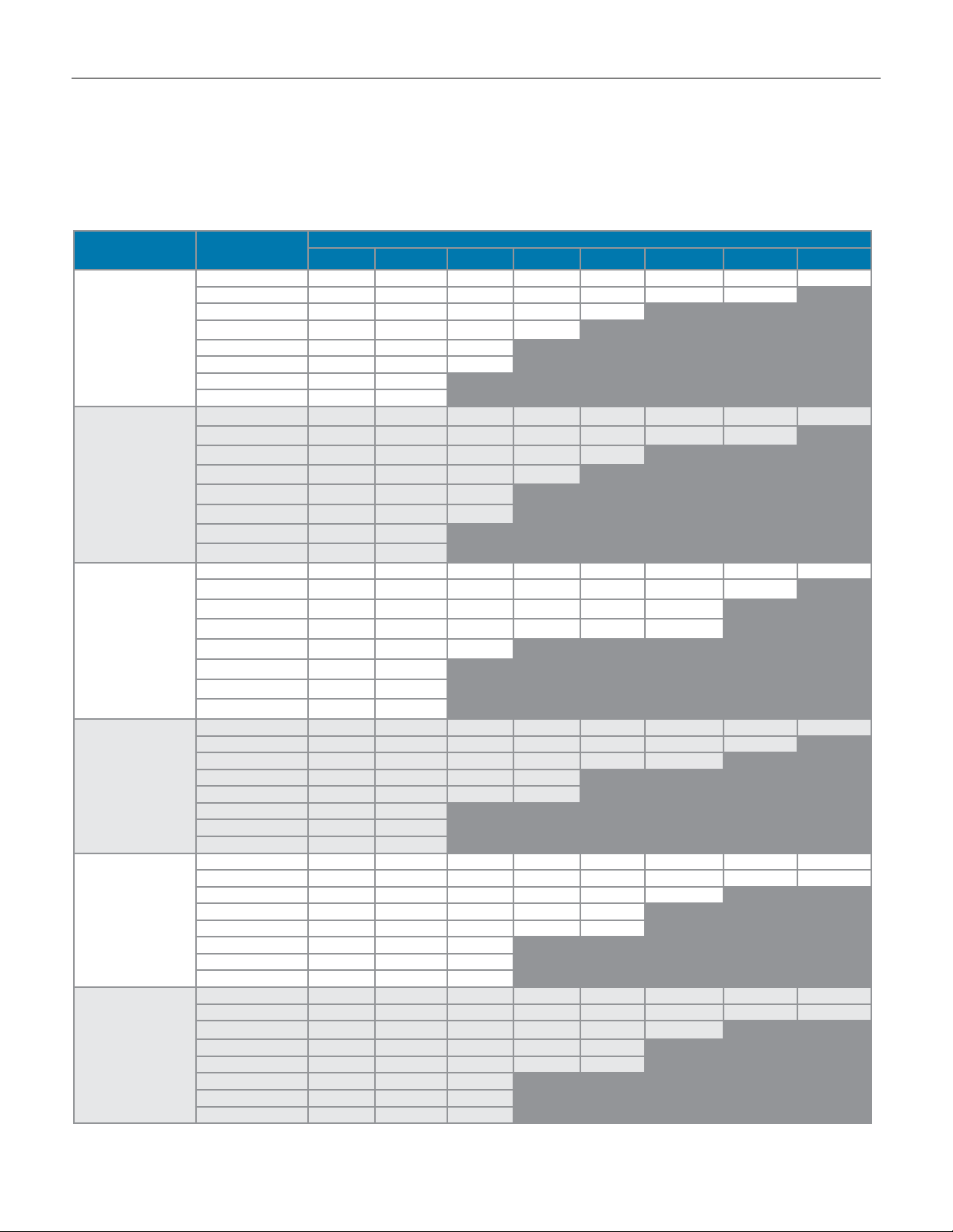
1" n2 Max Flow capacity: scFH
To select the orifice size for your valve you need to know P1 (inlet pressure). P2 (outlet pressure set point), and maximum flow in SCFH.
1. Select the row that best represents your outlet Set Pressure (P2)
2. Select the sub-row that is representative of your Inlet Pressure (P1)
3. Find the Flow rate in that sub-row that encompasses your maximum flow. Look at the orifice column heading to determine your specific orifice size.
Set Pressure Inlet (psi)
5 226 420 483 630 536 998 1172 1313
10 328 618 702 893 779 1206 1450
2" H20
(1-2.5" H20)
1" H20 Droop
2" H20 Boost*
3" H20
(2-5" H20)
1" H20 Droop
2" H20 Boost*
7" H20
(4-10" H20)
1" H20 Droop
2" H20 Boost*
28" H20
(5-30" H20)
5-1/2" H20 Droop
1.25 psi
(0.5 - 1.75 psi)
0.2 psi Droop
3 psi
(1 - 3.5 psi)
0.3 psi Droop
* Boost refers to a small rise in outlet pressure set point that can occur, and is characteristic of, this type of regulator when flow nears the valve's maximum capacity. To understand this
phenomenon and to determine your maximum flow requirements, see API 2000
20 493 872 1055 1376 803
40 786 1224 1681 2010
60 1073 1447 1872
80 1360 1455 1898
100 1648 1763
150 2146 2256
5 268 419 565 629 689 996 1307 1342
10 356 618 870 892 910 1205 1503
20 469 872 1266 1376 656
40 730 1224 1707 2010
60 963 1447 1926
80 1255 1455 1627
100 1534 1763
150 1981 2256
5 283 378 477 524 565 793 1024 848
10 380 585 791 722 653 1003 1345
20 488 871 1247 1684 2110 2177
35 673 1444 2188 2358 2525 3155
75 1221 2278 3317
90 1399 2623
100 1534 2836
150 1981 3687
5 318 478 636 760 883 991 1095 1130
10 388 613 831 1128 1424 1584 1741
30 373 1074 1756 2192 2608 2834
45 718 1596 2393 2892
60 929 2121 3302 3294
75 1139 2517
100 1449 3219
150 1871 4182
5 198 299 482 434 578 511 723 1012
10 267 378 593 608 890 756 1038 964
30 328 552 969 924 1193 1342
45 479 758 1197 1157 1396
60 624 998 1497 1398 1622
75 689 1229 1858
100 920 1609 2376
150 1211 2091 3081
5 159 238 318 346 371 408 442 742
10 237 355 475 571 672 710 752 831
30 266 550 825 921 1011 1337
45 479 758 1097 1157 1157
60 619 998 1376 1398 1410
75 689 1229 1708
100 852 1609 2387
150 1100 2091 3081
1/8" 3/16" 1/4" 5/16" 3/8" 7/16" 1/2" 9/16"
-4-
Orifice Size
Flow in this area is outside the operating
parameters of the valve
Flow in this area is outside the operating
parameters of the valve
Flow in this area is outside the operating
parameters of the valve
Flow in this area is outside the operating
parameters of the valve
Flow in this area is outside the operating
parameters of the valve
Flow in this area is outside the operating
parameters of the valve
Page 5
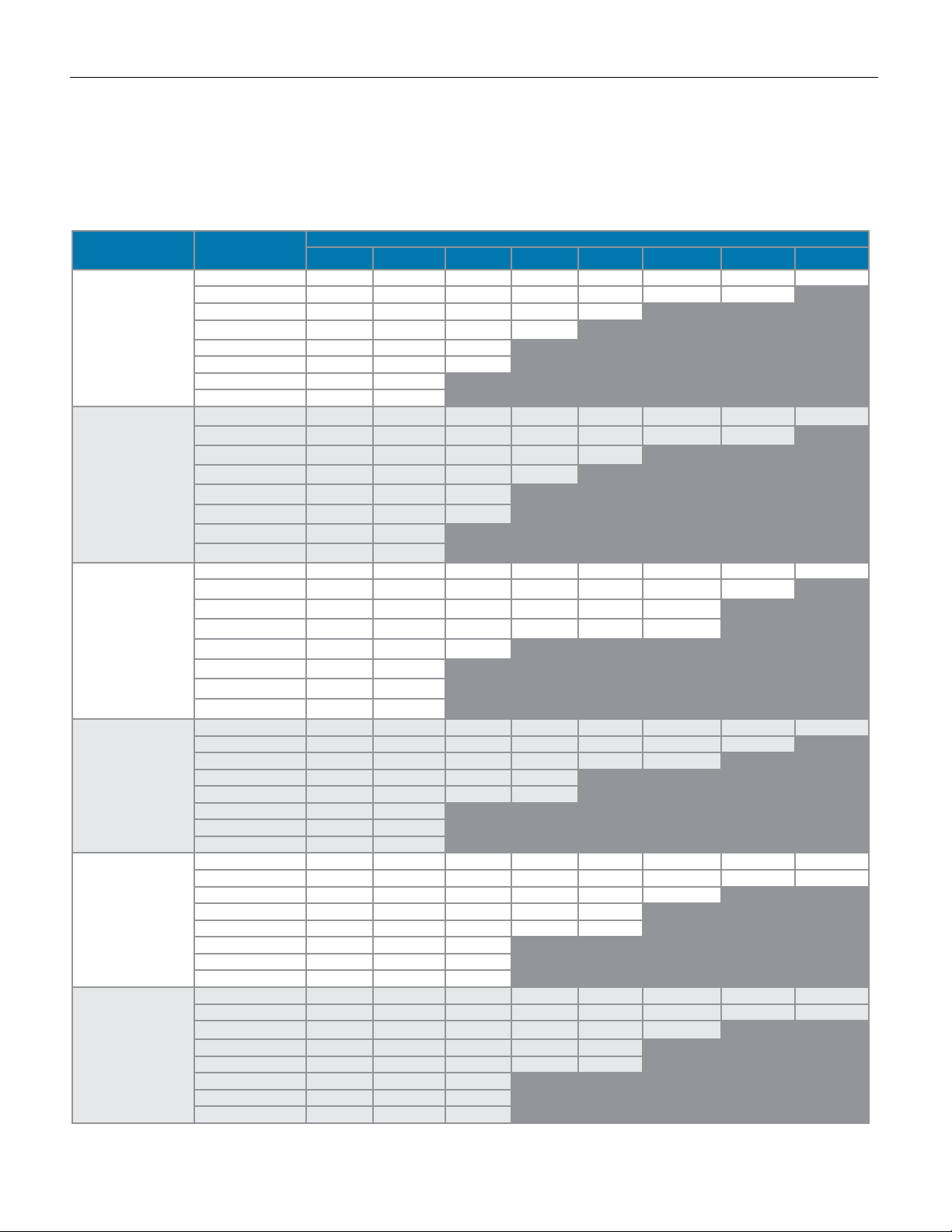
Mark 968 Sanitary GaS reGulator
1" n2 Max Flow capacity: nM3/H
To select the orifice size for your valve you need to know P1 (inlet pressure). P2 (outlet pressure set point), and maximum flow in NM3/H.
1. Select the row that best represents your outlet Set Pressure (P2)
2. Select the sub-row that is representative of your Inlet Pressure (P1)
3. Find the Flow rate in that sub-row that encompasses your maximum flow. Look at the orifice column heading to determine your specific orifice size.
Set Pressure Inlet (bar)
0.345 6.40 11.9 13.7 17.8 15.2 28.2 33.2 37.2
0.689 9.28 17.5 19.9 25.3 22.0 34.1 41.0
2" H20
(1-2.5" H20)
1" H20 Droop
2" H20 Boost*
3" H20
(2-5" H20)
1" H20 Droop
2" H20 Boost*
7" H20
(4-10" H20)
1" H20 Droop
2" H20 Boost*
28" H20
(5-30" H20)
5-1/2" H20 Droop
0,09 bar
(0.03 - 0,12 bar)
0,01 bar Droop
0,21 bar
(0,07 - 0,24 bar)
0,02 bar Droop
* Boost refers to a small rise in outlet pressure set point that can occur, and is characteristic of, this type of regulator when flow nears the valve's maximum capacity. To understand this
phenomenon and to determine your maximum flow requirements, see API 2000
1.38 14.0 24.7 29.9 38.9 22.7
2.76 22.2 34.6 47.6 56.9
4.14 30.4 41.0 53.0
5.52 38.5 41.2 53.7
6.89 46.6 49.9
10.3 60.7 63.8
0.345 7.58 11.9 16.0 17.8 19.5 28.2 37.0 38.0
0.689 10.1 17.5 24.6 25.2 25.8 34.1 42.5
1.38 13.3 24.7 35.8 38.9 18.6
2.76 20.7 34.6 48.3 56.9
4.14 27.3 41.0 54.5
5.52 35.5 41.2 46.0
6.89 43.4 49.9
10.3 56.1 63.8
0.345 8.01 10.7 13.5 14.8 16.0 22.4 29.0 24.0
0.689 10.8 16.6 22.4 20.4 18.5 28.4 38.1
1.38 13.8 24.7 35.3 47.7 59.47 61.6
2.41 19.1 40.9 61.9 66.7 71.5 89.3
5.17 34.6 64.5 93.9
6.21 39.6 74.2
6.89 43.4 80.3
10.3 56.1 104
0.345 9.00 13.5 18.0 21.5 25.0 28.1 31.0 32.0
0.689 11.0 17.6 23.5 31.9 40.3 44.8 49.3
2.07 10.6 30.4 49.7 62.0 73.8 80.2
3.10 20.3 45.2 67.7 81.8
4.14 26.3 60.0 93.5 93.2
5.17 32.2 71.2
6.89 41.0 91.1
10.3 53.0 118
0.345 5.6 8.46 13.6 12.3 16.4 14.5 20.5 20.5
0.689 7.56 10.7 16.8 17.2 25.2 21.4 29.4 29.4
2.07 9.28 15.6 27.4 26.2 33.8 38.0
3.10 13.6 21.5 33.9 32.7 39.5
4.14 17.7 28.2 42.4 39.6 45.9
5.17 19.5 34.8 52.6
6.89 26.0 45.5 67.2
10.3 34.3 59.2 87.2
0.345 4.5 6.74 9.0 9.8 10.5 11.6 12.5 21.0
0.689 6.7 10.0 13.4 16.2 19.0 20.1 21.3 23.5
2.07 7.53 15.6 23.4 26.1 28.6 37.8
3.10 7.90 21.5 31.1 32.7 32.7
4.14 17.5 28.2 38.9 39.6 39.9
5.17 19.5 34.8 48.3
6.89 24.1 45.5 67.6
10.3 31.1 59.2 87.2
1/8" 3/16" 1/4" 5/16" 3/8" 7/16" 1/2" 9/16"
-5-
Orifice Size
Flow in this area is outside the operating
parameters of the valve
Flow in this area is outside the operating
parameters of the valve
Flow in this area is outside the operating
parameters of the valve
Flow in this area is outside the operating
parameters of the valve
Flow in this area is outside the operating
parameters of the valve
Flow in this area is outside the operating
parameters of the valve
Page 6
Mark 968 Sanitary GaS reGulator
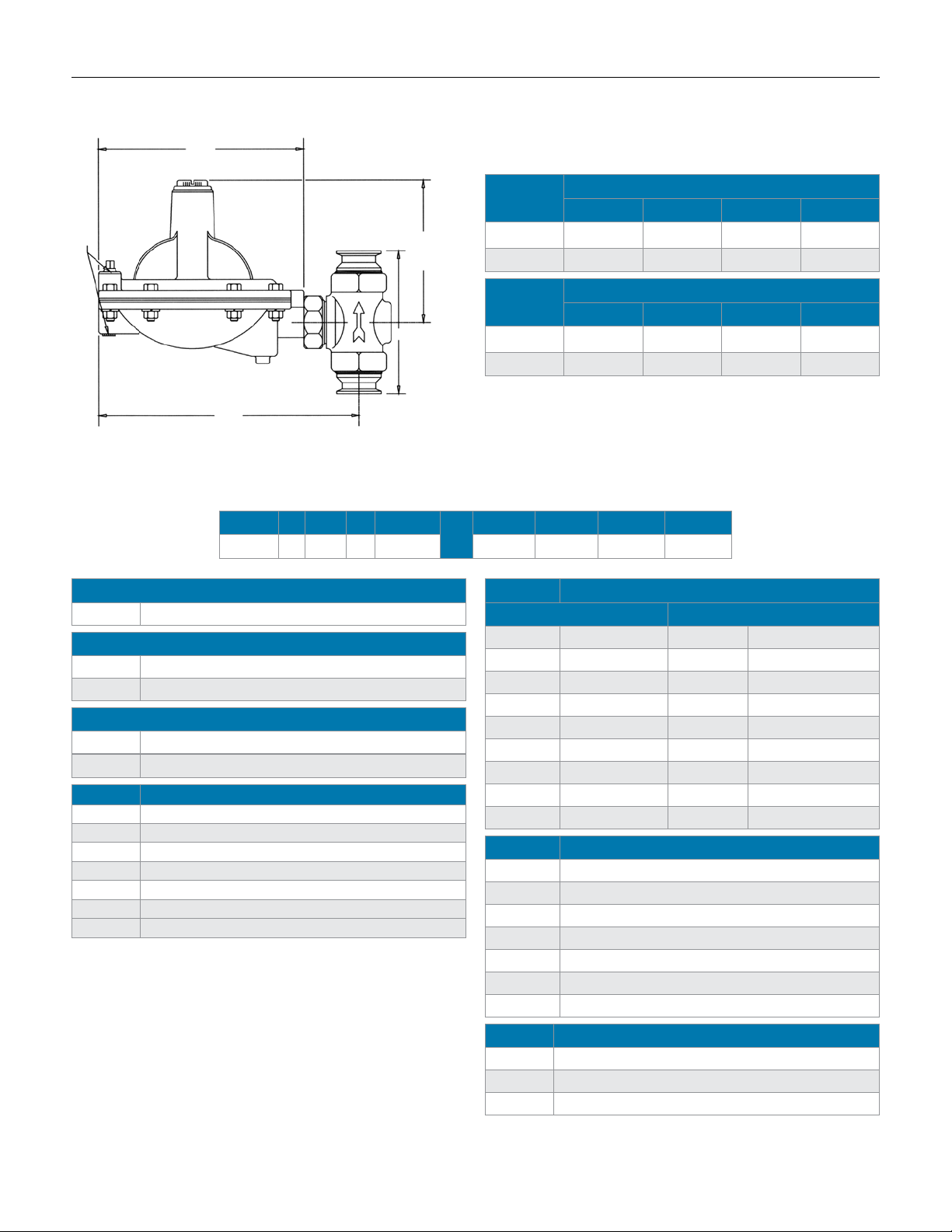
diMensions
D
1/4" NPT
A
B
ordering scHeMatic (3/4" - 1")
Model Size Material
— —
Model
968 Mark 968 Sanitary Gas Regulator
Size
075 3/4" (DN20)
100 1" (DN25)
Body Material
S6 ASTM A351 Gr. CF8M 316
6L
1&2 Connections & Body Finish
TC Tri Clamp - Electropolished Finish
CT Tri-Clamp - Standard Finish
DC DIN - Tri Clamp - Electropolished Finish
CD DIN - Tri-Clamp - Standard Finish
SC ISO - Tri Clamp - Electropolished Finish
CS ISO - Tri-Clamp - Standard Finish
ZZ Non-Standard
SA 351 Gr. CF3M, 316L
Valve
Size
A B C D
Dimensions, Inches
3/4" 5.88 11.31 5.75 9.00
C
1" 5.88 11.31 5.75 9.00
Valve
Size
A B C D
Dimensions, Mm
DN20 149,4 287,3 146,1 228,6
DN25 149,4 287,3 146,1 228,6
1&2 3&4 5&6 7&8
/
3&4 Orice Finish
Standard Electropolish
10 1/8" (3mm) 01 1/8" (3mm)
20 3/16" (5mm) 02 3/16" (5mm)
30 1/4" (6mm) 03 1/4" (6mm)
40 5/16" (8mm) 04 5/16" (8mm)
50 3/8" (10mm) 05 3/8" (10mm)
60 7/16" (11mm) 06 7/16" (11mm)
70 1/2" (13mm) 07 1/2" (13mm)
80 9/16" (14mm) 08 9/16" (14mm)
ZZ Non-Standard ZZ Non-Standard
5&6 Range
01 1"-2.5" W.C. (2,5-6,2 mbar)
02 2"-5.5" W.C. (5,0-13,7 mbar)
03 4"-10" W.C. (10,0-24,9 mbar)
04 5"-30" W.C. (12,4-74,7 mbar)
05 0.5-1.75 psi (0,03-0,12 bar)
06 1-3.5 psi (0,07-0,24 bar)
ZZ Non-Standard
7&8 Actuator Finish & Diaphragm
SD Electropolished w/Viton (FDA)
DS Standard w/VIton (FDA)
ZZ Non-Standard
-6-
Page 7
Mark 968 Series
Sanitary Gas Regulator (1-1/2" – 2")
The 1-1/2" and 2" valves are for use on large tank
blanketing applications or other low pressure gas
regulation. In a tank blanketing application, the
Mark 968 is used to control the ow of the blanketing gas into the tank to maintain the proper positive
pressure. Once the blanket has been established,
a small ow of nitrogen is continually admitted to
the tank to keep the blanket fresh. These valves are
often used in conjunction with the Mark 958 back
pressure gas regulator, used to vent gas from the
tank to prevent blanketing pressure from rising to a
level that could damage the tank.
The Mark 968 comes standard with an extra large
diaphragm to give set point control as low as 2.0"
W.C. (4,98 mbar). In addition, the "S" pattern body
design allows for high ow capacity and bubble
tight shutoff.
speciFications
Line Sizes: 1-1/2" (DN40), 2" (DN50)
End Connections
• Clamp — ISO, DIN, Tri-Clamp
• Flanged — 150#, 300#, Sanitary
• Others upon request
Materials
• Body: Stainless Steel (SA351/CF8M)
• Trim: 316/316L Stainless Steel
• Seat: 316/316L Stainless Steel with Viton (FDA)
• Diaphragm: Viton (FDA)
Shutoff: ANSI Class VI
Ranges:
• 2 to 5 inches w.c. (4,98 to 12,5 mbar)
• 4 to 8 inches w.c. (9,96 to 19,93 mbar)
• 8 to 28 inches w.c. (19,93 to 69,75 mbar)
• 10 to 17 inches w.c. (24,91 to 42,35 mbar)
• 14 to 28 inches w.c. (34,87 to 69,75 mbar)
• 0.75 to 1 psi (51,71 to 68,95 mbar)
• 1 to 2 psi (68,95 to 137,90 mbar)
• 1.5 to 3 psi (0,10 to 0,21 bar)
• 3 to 5 psi (0,21 to 0,34 bar)
Cv Rating: 23 (20 Kv)
Pressure Temperature Rating: 25 psi @ 100°F (1,72 bar @
27,8 °C), 25 psi @ 275°F (1,72 bar @ 135°C)
Maximum Pressure Drop: 25 psig (1,72 bar)
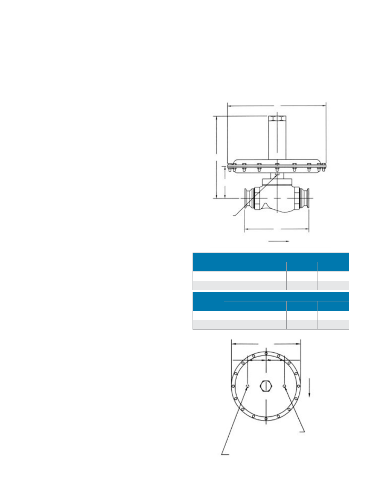
diMensions
D
C
B
3/4" FNPT
Sensing Port
A
Flow
Valve
Size
1-1/2" 8.75 4.93 12.32 15.00
2" 8.75 4.93 12.32 15.00
Valve
Size
DN40 222,3 125,2 312,9 381,0
DN50 222,3 125,2 312,9 381,0
4.75
(120,7)
-7-
A B C D
A B C D
3/4" FNPT Sensing Tap (Bottom)
Dimensions, Inches
Dimensions, Inches
15.0
(381)
3/4" FNPT Vent (Top)
Flow
Page 8
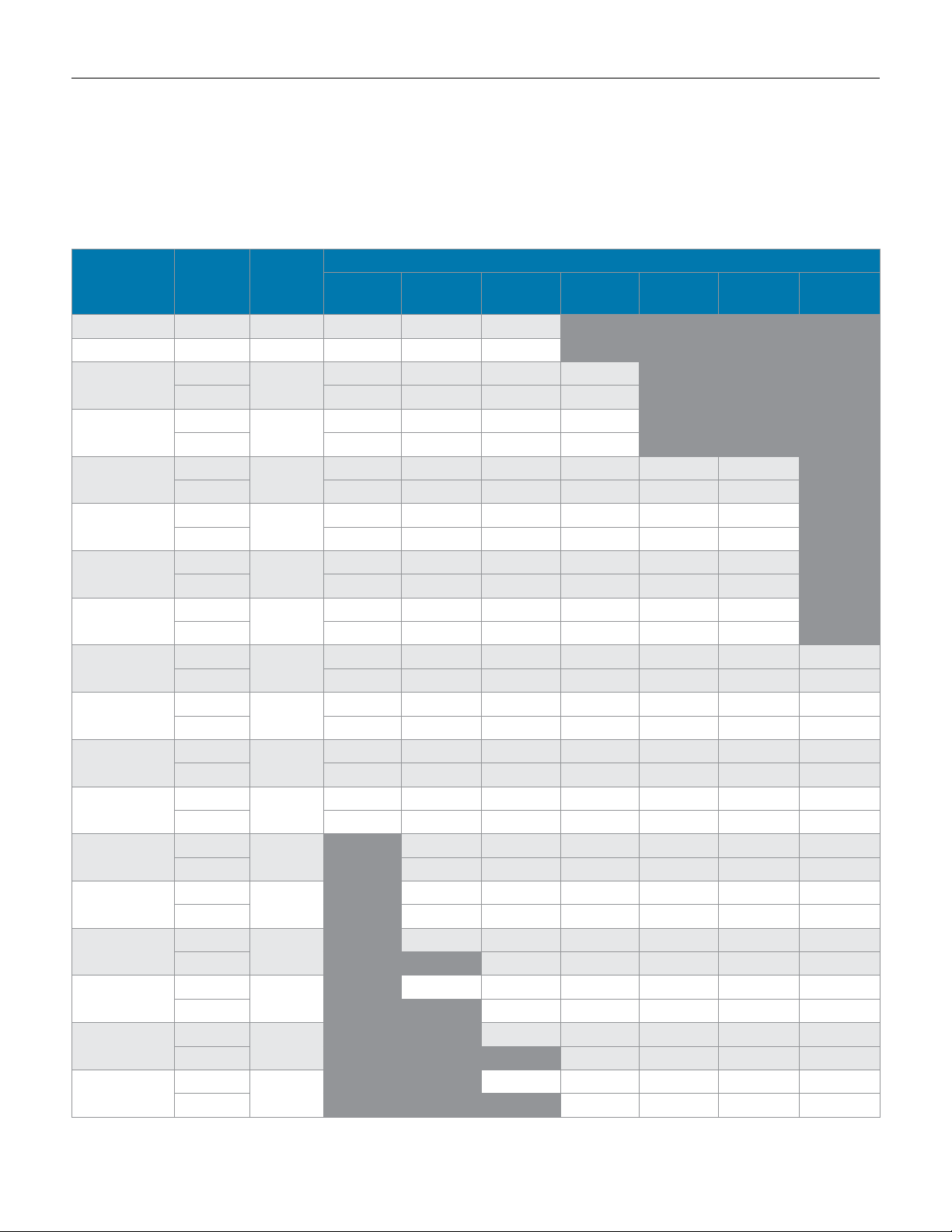
Mark 968 Sanitary GaS reGulator
1-1/2" n2 Flow capacities: scFH (sHaded), nM3/H (unsHaded)
To find the maximum flow rate that this valve can control to, you need to know P1 (inlet pressure), P2 (outlet pressure set point), and
maximum flow in SCFH.
1. Select the Range row that encompasses your outlet Set Pressure (P2). 3. Select the column that best represents your Inlet Pressure (P1).
2. Select the sub-row that is closest to your actual outlet Set Pressure (P2) 4. The maximum flow rate that the valve can regulate is the number represented at the
intersection of the sub row and the Inlet Pressure column.
Outlet
Range
Pressure
Set Point
Accuracy
2.0 psi
(0,14 bar)
3.0 psi
(0,21 bar)
5.0 psi
(0,34 bar)
2.0-5.0" WC 3.0" WC 0.75" WC 4853 5185 5999
4,98-12,5 mbar 7,47 mbar 1,87 mbar 137 147 170
4.0-8.0" WC
9,96-19,93 mbar
8.0-28.0" WC
19,93-69,75 mbar
10.0-17.0" WC
24,91-42,35 mbar
14.0-28.0" WC
34,87-69,75 mbar
0.75-1 psi
51,71-68,95 mbar
1-2 psi
68,95-137,0 mbar
1.5-3 psi
0.10-0,21 bar
3-5 psi
0,21-0,34 bar
Nitrogen at 0.97 s.g. in scfh and Nm
5.0" WC
7.0" WC 4987 5747 6482 6984
12,45 mbar
17,44 mbar 141 163 184 198
10.0" WC
25.0" WC 4293 4672 4357 4858 6876 7220
24,91 mbar
62,27 mbar 122 132 123 138 195 204
12.0" WC
15.0" WC 4297 5200 7111 9778 10310 10748
28,89 mbar
37,36 mbar 122 147 201 277 292 304
15.0" WC
25.0" WC 3123 4487 6675 9057 10792 11608 12938
37,36 mbar
62,27 mbar 88 127 189 256 306 329 366
0.75 psi
1 psi 4638 6286 9501 11557 13892 15253 17026
51,71 mbar
68,75 mbar 131 178 269 327 393 432 482
1.5 psi
2.0 psi 3505 7588 11281 13764 15351 17206
0,10 bar
0,14 bar 99 215 319 390 435 487
2.0 psi
3.0 psi 6057 10924 13626 15327 17252
0,14 bar
0,21 bar 172 309 386 434 489
3.5 psi
5.0 psi 9639 12792 14682 16688
0,24 bar
0,34 bar 273 362 416 473
1" WC
2,49 mbar
1.5" WC
3,74 mbar
2" WC
4,98 mbar
2.5" WC
6,23 mbar
0.25 psi
12,93 bar
0.3 psi
20,69 mbar
0.4 psi
27,50 mbar
0.5 psi
34,38 mbar
3
/h.
Operation in shaded areas not recommended.
4675 5532 6748 8599
132 157 191 243
5601 5297 6622 7720 8468 7638
159 150 188 219 240 216
4582 5984 7169 10367 10228 10838
130 169 203 294 290 307
4070 5737 8261 10811 12068 13414 13120
115 162 234 306 342 380 372
4843 7253 9628 11573 13833 15278 17038
137 205 273 328 392 433 482
4352 8736 11529 13957 15514 17358
123 247 326 395 439 492
3929 8034 11339 13871 15466 17332
111 228 321 393 438 491
Flow in this area is outside
the operating parameters of
the valve
-8-
Inlet Pressure
10.0 psi
(0,69 bar)
15.0 psi
(1,03 bar)
Flow in this area is outside the operating
20.0 psi
(1,38 bar)
parameters of the valve
25.0 psi
(1,72 bar)
3507 10781 13598 15365 17332
99 305 385 435 491
Page 9
Mark 968 Sanitary GaS reGulator
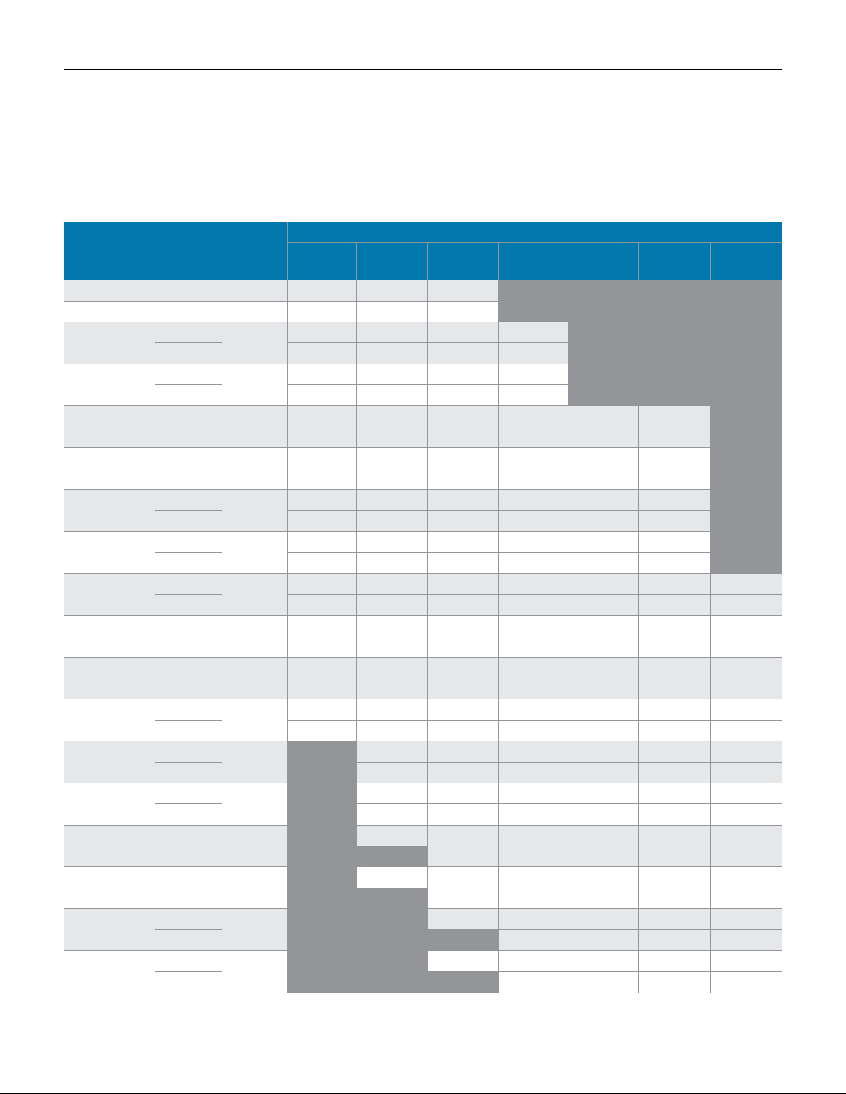
2" n2 Flow capacities: scFH (sHaded), nM3/H (unsHaded)
To find the maximum flow rate that this valve can control to, you need to know P1 (inlet pressure), P2 (outlet pressure set point), and maximum flow in SCFH.
1. Select the Range row that encompasses your outlet Set Pressure (P2). 3. Select the column that best represents your Inlet Pressure (P1).
2. Select the sub-row that is closest to your actual outlet Set Pressure (P2) 4. The maximum flow rate that the valve can regulate is the number represented at the
intersection of the sub row and the Inlet Pressure column.
Outlet
Range
Pressure
Set Point
Accuracy
2.0 psi
(0,14 bar)
3.0 psi
(0,21 bar)
5.0 psi
(0,34 bar)
2.0-5.0" WC 3.0" WC 0.75" WC 5392 5761 6666
4,98-12,5 mbar 7,47 mbar 1,87 mbar 153 163 189
4.0-8.0" WC
9,96-19,93 mbar
8.0-28.0" WC
19,93-69,75 mbar
10.0-17.0" WC
24,91-42,35 mbar
14.0-28.0" WC
34,87-69,75 mbar
0.75-1 psi
51,71-68,95 mbar
1-2 psi
68,95-137,0 mbar
1.5-3 psi
0.10-0,21 bar
3-5 psi
0,21-0,34 bar
Nitrogen at 0.97 s.g. in scfh and Nm
5.0" WC
7.0" WC 5541 6385 7202 7760
12,45 mbar
17,44 mbar 157 181 204 220
10.0" WC
25.0" WC 4770 5191 4841 5398 7640 8022
24,91 mbar
62,27 mbar 135 147 137 153 216 227
12.0" WC
15.0" WC 4775 5778 7901 10864 11456 11942
28,89 mbar
37,36 mbar 135 164 224 308 324 338
15.0" WC
25.0" WC 3470 4986 7416 10063 11991 12898 14376
37,36 mbar
62,27 mbar 98 141 210 285 340 365 407
0.75 psi
1 psi 5153 6984 10556 12841 15436 16948 18918
51,71 mbar
68,75 mbar 146 198 299 364 437 480 536
1.5 psi
2.0 psi 3895 8431 12534 15293 17056 19118
0,10 bar
0,14 bar 110 239 355 433 483 541
2.0 psi
3.0 psi 6731 12138 15140 17030 19169
0,14 bar
0,21 bar 191 344 429 482 543
3.5 psi
5.0 psi 10710 14214 16314 18543
0,24 bar
0,34 bar 303 402 462 525
1" WC
2,49 mbar
1.5" WC
3,74 mbar
2" WC
4,98 mbar
2.5" WC
6,23 mbar
0.25 psi
12,93 bar
0.3 psi
20,69 mbar
0.4 psi
27,50 mbar
0.5 psi
34,38 mbar
3
/h.
Operation in shaded areas not recommended.
5195 6147 7498 9554
147 174 212 271
6223 5885 7358 8578 9408 8486
176 167 208 243 266 240
5091 6649 7965 11519 11365 12042
144 188 226 326 322 341
4523 6374 9179 12013 13409 14904 14578
128 180 260 340 380 422 413
5382 8059 10698 12859 15370 16976 18931
152 228 303 364 435 481 536
4835 9706 12810 15508 17238 19286
137 275 363 439 488 546
4365 8927 12599 15412 17185 19258
124 253 357 436 487 545
Flow in this area is outside
the operating parameters of
the valve
-9-
Inlet Pressure
10.0 psi
(0,69 bar)
15.0 psi
(1,03 bar)
Flow in this area is outside the operating
20.0 psi
(1,38 bar)
parameters of the valve
25.0 psi
(1,72 bar)
3897 11979 15109 17072 19258
110 339 428 483 545
Page 10
Mark 968 Sanitary GaS reGulator
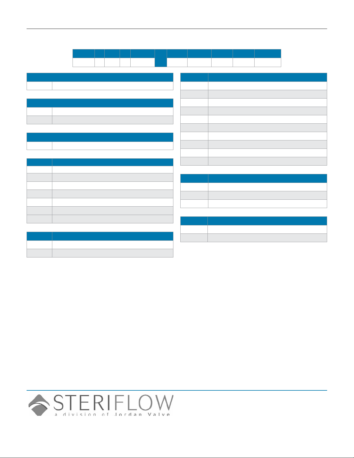
ordering scHeMatic (1-1/2" – 2")
MK968/0812/10K/AB
Model Size Material
— —
Model
968 Mark 968 Sanitary Gas Regulator
Size
150 1-1/2" (DN40)
200 2" (DN50)
Body Material
S6 Stainless Steel
1&2 Connections & Body Finish
TC Tri Clamp - Electropolished Finish
CT Tri-Clamp - Standard Finish
DC DIN - Tri Clamp - Electropolished Finish
CD DIN - Tri-Clamp - Standard Finish
SC ISO - Tri Clamp - Electropolished Finish
CS ISO - Tri-Clamp - Standard Finish
ZZ Non-Standard
3&4 Seat & Diaphragm / Seat Finish
VN Viton / Electropolished Seat
NV Viton / Standard Finish Seat
1&2 3&4 5&6 7&8 9&10
/
5&6 Range
07 2-5" WC (4,98-12,5 mbar)
08 4-8" WC (9,96-19,93 mbar)
09 8-28" WC (19,93-69,75 mbar)
10 10-17" WC (24,91-42,35 mbar)
11 14-28" WC (34,87-69,75 mbar)
12 0.75-1 psi (51,71-68,95 mbar)
13 1-2 psi (68,95-137,90 mbar)
14 1.5-3 psi (0,10-0,21 bar)
15 3-5 psi (0,21-0,34 bar)
ZZ Non-Standard
7&8 Actuator Finish
SD Electropolished
DS Standard
ZZ Non-Standard
9&10 Bushing
TF Teon-FDA
ZZ Non-Standard
Steriflow, a division of Jordan Valve
3170 Wasson Road • Cincinnati, OH 45209
513.533.5600 • 800.543.7311 • 513.871.0105 (f)
steri[email protected] • www.steriowvalve.com
Steriflow Valve reserves the right to make revisions to its product, specifications, literature and related information without notice. Please visit our
website at www.steriflowvalve.com for the latest information on our products.
 Loading...