

Page 1
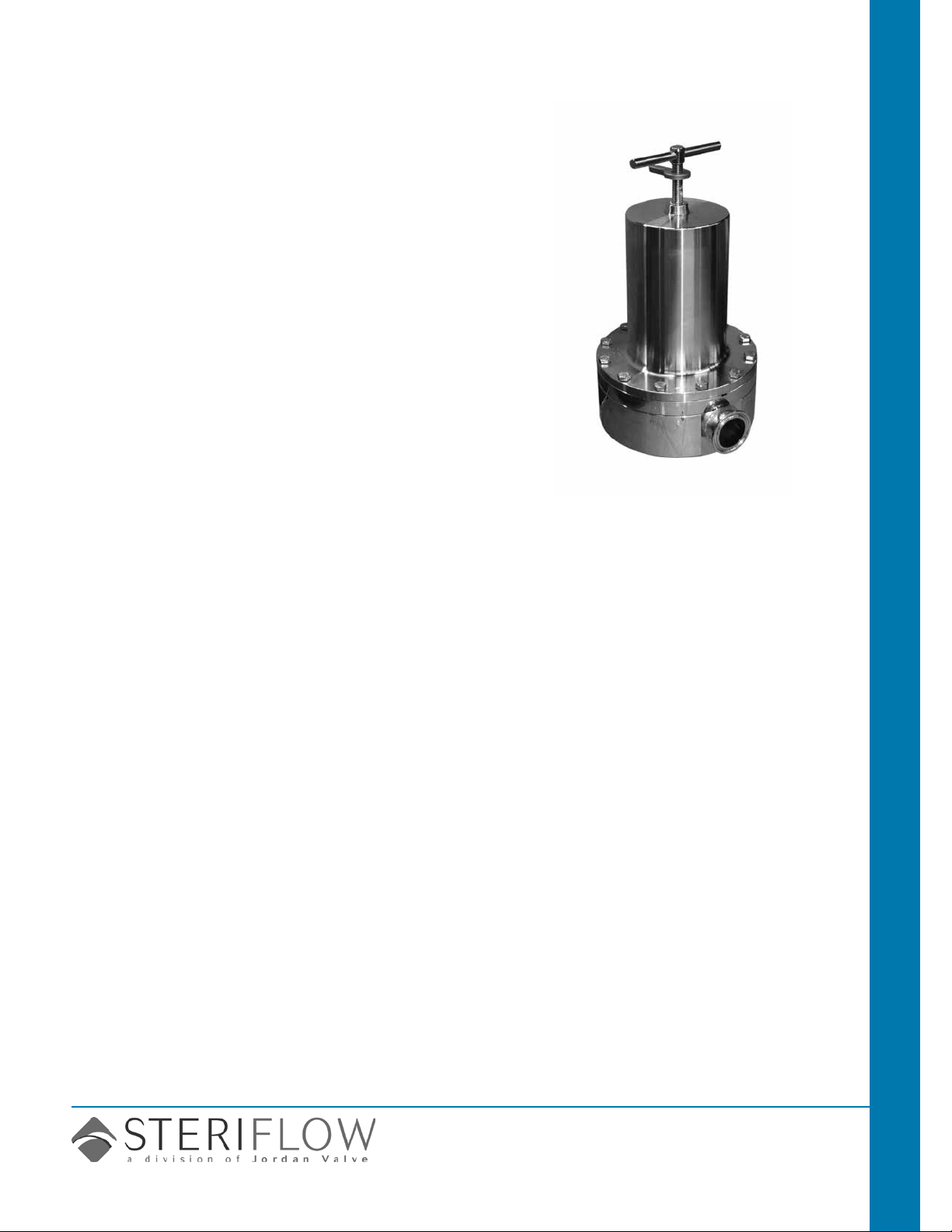
Mark 96 Series
Sanitary Pressure Regulators
The Mark 96 Sanitary Pressure Regulator is designed to
regulate pressure in systems requiring the maintenance
of sanitary conditions.
The Mark 96 operates by sensing pressure under the
diaphragm on the downstream side of the seat. As the
downstream pressure approaches the set point, the
force caused by the pressure acting on the diaphragm
overcomes the force of the range spring, and the plug
begins to move up toward closed. This reduces the
downstream pressure and maintains the set point. If the
pressure underneath the diaphragm begins to fall, the
spring forces the plug to move down towards open, to
allow the set point to be maintained.
CRN Registration Number Available
Sanitary Valves Mark 96 Sanitary Pressure Regulators
Features
• New! Optional Gauge Port
• CRN Registration Number Available
• Soft seat capability for ANSI Class VI shutoff
• No guiding surfaces in the uid below the diaphragm
in the wetted area. ASME BPE compliant
• 100% 316L barstock body – no wetted parts made
from castings
• Self-draining
• Best Accuracy (least droop -set point offset) in the
industry. Ask your rep for a MK96 performance
calculator demonstration
• Clean-in-Place, Steam-in-Place – dome lock pin to
allow CIP/SIP
• Jorlon diaphragm: PTFE based material provides
excellent chemical resistance and extremely long life in
steam service. Far superior to other elastomer or metal
diaphragm materials. Ask your local Representative for
cycle testing information.
Documentation
The following documentation is shipped at no charge:
• Steriow Unicert: Certicate of Compliance for:
- Material, including MTR’s
- Surface Finish
- FDA/USP Class VI
• Traceability:
- Each Unicert includes individual valve serial
numbers, heat numbers and attached MTR’s directly
traceable to the valve serial number, and heat
numbers on all wetted metallic components.
available Finishes
Body
• Standard: 20 Ra µin (0,5 Ra µm) (ASME
BPE SF5) mechanical nish and electropolish on inside wetted surfaces; 40 Ra µin
(1 Ra µm) and electropolish on exterior.
• Optional: 20 Ra µin (0,5 Ra µm) SF5 me-
chanical nish and electropolish on external
surfaces; 8 Ra µin (0,2 Ra µm) nish on
internal or external nishes and electropolish
(Better than SF4)
Spring Housing and Handle
• Standard: machine nished 316SST,
electropolished
• Optional: 20 Ra µin (0,5 Ra µm) mechanical
nish and electropolish on external surfaces
(SF5). 8 Ra µin (0,2 Ra µm) nish on external surfaces on all sizes and electropolish.
(Better than SF4)
Adjusting Screw
• Standard: 32Ra µin electropolished (Note:
adjusting screw is a threaded part)
• Optional: 20 Ra µin (0,5 Ra µm) mechani-
cal nish and electropolish nish (SF5)
applications
A wide variety of applications exist for the
MK96 in the pharmaceutical, biotech, healthcare, food & beverage and other industries.
Steriflow by Jordan Valve
3170 Wasson Road • Cincinnati, OH 45209
513.533.5600 • 800.543.7311 • 513.871.0105 (f)
sterifl[email protected] • www.steriflowvalve.com
Page 2
Mark 96 SerieS Sanitary PreSSure regulatorS
speciFications – o-ring Diaphragm
Sizes: 3/4" (DN20), 1" (DN25), 1-1/2" (DN40), 2"
(DN50), 3" (DN80)
End Connections
• Quick disconnect ttings (to match Tri-Clamp®
tting)
• DIN/ISO sanitary connections
Body Connections: Mark 96 – Bolted – Standard for
all sizes
Body & Trim Materials: 316L Stainless Steel (ASTM
A479)
Seat Materials
• Standard hard seat – integral 316L SST seat
• Optional soft seat
– Jorlon (for Cv 1.5, 1" size and above) (FDA &
USP Class VI) for steam and hot uid service to
338°F (170°C)
– Teon (for Cv 2.5, 1" size and above) to 252°F
(122°C) continuous or 275°F (135°C) intermittent
[not to exceed 15 min. in a one hour period] FDA,
USP Class VI
– PEEK (3/4" and above) (FDA & USP Class VI)
for steam and hot uid service to 350° (177°C)
Note: consult factory for how to order PEEK soft seat
materials
Spring Housing Materials
• CF8M cast SST (3/4" – 1")
• Fabricated 316L SST (1-1/2" – 3")
Diaphragm Materials
• 316L SST
• EPDM/Nylon (to 275°F, 135°C), FDA only
• Jorlon (to 400°F, 204°C) – FDA, USP Class VI
• Ulta-thin Jorlon (to 400°F, 204°C), FDA, USP
Class VI (for use with 3-8 range spring only)
O-Ring Materials
• EPDM (to 275°F, 135°C) – FDA, USP Class VI
• Buna-N (to 225°F, 107°C) – FDA
• Viton (to 400°F, 204°C) – FDA, USP Class VI
• Silicone (to 400°F, 204°C) – FDA, USP Class VI
• Teon-Encapsulated Viton (to 400°F, 204°C) –
FDA, USP Class VI (1-1/2" - 3" only)
• Teon-Encapsulated Silicone (to 400°F, 204°C) –
FDA, USP Class VI
Shutoff: ANSI Class III hard seat or Class VI soft seat
Body Pressure Temperature Rating: (dependent
upon construction)
Valve Size PSIG @ 100°F PSIG @ 450°F
3/4" & 1" 350 (24,1 bar) 250 (17,2 bar)
1-1/2" , 2", & 3" 200 (13,8 bar) 200 (13,8 bar)
Pressure on 1/2", 3/4" & 1" size limited to 225 psig (15,5 bar)
@ 100°F and 200 psig (13,8 bar) @ 400°F if using Ultra-thin
Jorlon diaphragm.
Note: for 1/2" size, refer to our Mark 96C datasheet
Set Point Spring Ranges
Valve Size Set Point Ranges, PSI (bar)
3-8* (0,2-0,5), 5-25 (0,37-1,7), 15-50
3/4" & 1"
1-1/2"
2" 10-25 (0,7-1,7) or 15-60 (1,0-4,1)
3" 15-25 (1,0-1,7) or 15-60 (1,0-4,1)
* Range available with elastomer or Ultra-thin Jorlon
diaphragm only. Maximum pressure drop 40 psi
(1,0-3,4), 40-90 (2,7-6,2), or 75-135
(5,2-9,3)
10-25 (0,7-1,7), 15-50 (1,0-3,4) or
35-100 (2,4-6,9)
.
Cv (Kv) Ratings:
Valve
Size
3/4"*** 1.5 (1,3) 3.8 (3,27)
1"***
1-1/2" 4.5 or 10.0 (3,9 or 8,6) 6.7 (5,76); 26.3 (22,6)
2"
3"
** Not available with metal diaphragms, Jorlon and other
elastomers acceptable
*** When using the 3-8 range spring the following sizing limits apply:
For example a 1" Cv5.5 valve with a 3-8 range spring, if the
customer’s set point is P2 = 8 psi, then the actual Cv sizing
should not exceed 2.75Cv. If the customer’s intended set
point is P2 = 5 psi, then the actual Cv sizing should not exceed
1.8Cv and if their set point is P2 = 3 psi, then the actual Cv sizing should not exceed 1.38 Cv.
Available Cv (Kv)
1.5, 2.5, 4.5, 5.5**,
6.1**
(1,3; 2,2; 3,9; 4,7; 5,3)
10.0 or 19.0 (8,6 or
16,3)
10.0 or 23.0 (8,6 or
19,8)
Set Point Sizing Limit (of rated capacity)
8 50%
5 33%
3 25%
Cv for Relief Valve
Sizing
10.7 (9,2)
16.5 (14,2), 56.5 (48,6)
16.5 (14,2); 67.1 (57,7)
Maximum Allowable Pressure Differential: 200 psi
(3-8 spring range has a max of 40 psi)
-2-
Page 3
Mark 96 SerieS Sanitary PreSSure regulatorS
Note: Steriow does not recommend using metal seated trim
on any service where the ow will be deadheaded downstream of the pressure reducing regulator. Use an appropriate
Teon, Jorlon or Peek soft seat for the trim instead.
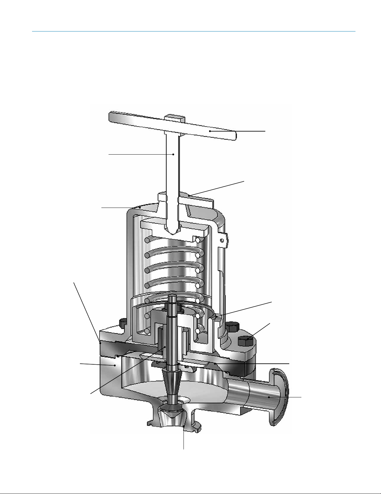
Features & beneFits
316 adjusting screw
316 T-handle for easy
handling and setpoint
adjustment
Thumblock for securing
and retaining setpoint
316 Stainless Steel
spring housing
100% barstock
body and trim
Standard optional
TM
3/4" Tri-Clamp
gauge ports available at 90°, 180°
and 270° from
outlet
CIP/SIP dome lock
Bolted bonnet for increased
safety and pressure/
temperature rating
Jorlon diaphragm
provides long life
Guiding above
diaphragm area,
not in seat/orice,
to eliminate metalto-metal particulate
generation
INLET
No threads in contact with
media
-3-
OUTLET
Self-draining
design with
20 Ra (SFV5)
mechanical and
electropolished
internals (in this
orientation)
Page 4
Mark 96 SerieS Sanitary PreSSure regulatorS
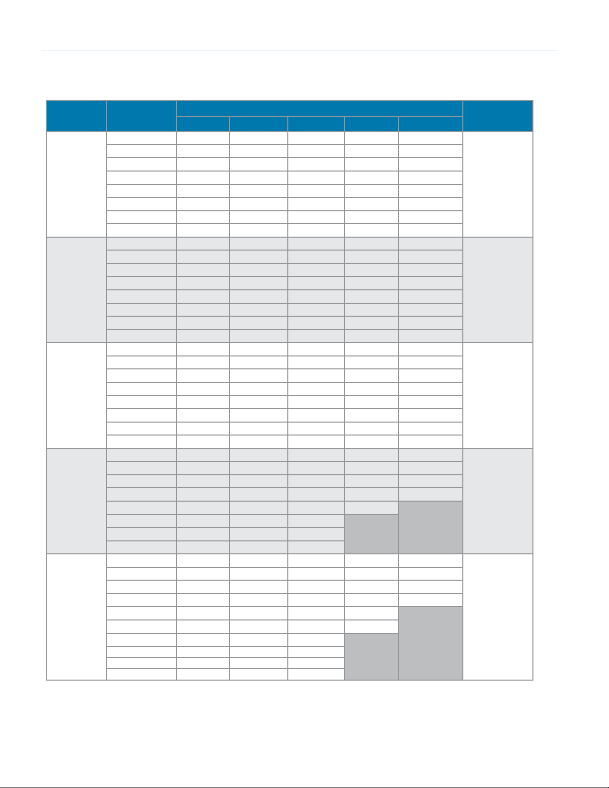
capacity cv at various Droop %
Mark 96
3/4"
1.5 Cv
15 to 50 psi
range
1"
4.5 Cv
15 to 50 psi
range
1-1/2"
10 Cv
15 to 50 psi
range
2"
19 Cv
15 to 60 psi
range
3"
23 Cv
15 to 60 psi
range
Set Pressure
PSIG
15 0.10 0.20 0.31 0.42 0.65
20 0.12 0.26 0.39 0.54 0.83
25 0.15 0.31 0.47 0.64 1.01
30 0.18 0.36 0.55 0.75 1.17
35 0.20 0.41 0.63 0.85 1.34
40 0.22 0.46 0.70 0.96 1.50
45 0.25 0.51 0.77 1.06 1.50
50 0.27 0.55 0.85 1.16 1.50
15 0.30 0.61 0.93 1.26 1.95
20 0.37 0.77 1.18 1.61 2.50
25 0.46 0.93 1.42 1.93 3.02
30 0.53 1.08 1.65 2.25 3.52
35 0.60 1.23 1.88 2.56 4.02
40 0.67 1.37 2.10 2.87 4.50
45 0.74 1.52 2.32 3.18 4.50
50 0.81 1.66 2.55 3.48 4.50
15 0.59 1.20 1.85 2.54 4.05
20 0.66 1.36 2.10 2.91 4.68
25 0.72 1.48 2.30 3.19 5.16
30 0.77 1.57 2.45 3.40 5.55
35 0.80 1.65 2.57 3.58 5.86
40 0.83 1.71 2.67 3.73 6.13
45 0.86 1.76 2.75 3.85 6.35
50 0.88 1.80 2.82 3.95 6.53
15 1.89 3.85 5.84 7.87 12.02
20 2.66 5.40 8.19 11.04 16.88
25 3.48 7.08 10.73 14.46 19.00
30 4.41 8.91 13.47 18.17 19.00
35 5.37 10.92 16.52 19.00
40 6.45 13.16 19.00
45 7.77 15.68 19.00
50 9.23 18.54 19.00
15 4.09 6.83 9.40 11.81 16.20
20 5.03 8.56 11.81 14.79 20.10
25 6.31 10.99 15.23 19.11 23.00
30 7.29 12.73 17.60 21.98 23.00
35 8.24 14.42 19.85 23.00
40 9.17 16.04 21.98 23.00
45 10.09 17.60 23.00
50 10.99 19.11 23.00
55 11.87 20.57 23.00
60 12.73 21.98 23.00
5% 10% 15% 20% 30%
7
Cv for Relief
Valve Sizing
3.8
10.7
26.3
56.5
67.1
Note: for capacity Cv and performance at other conditions, please visit the Technical Library on our website at
www.steriowvalve.com
-4-
Page 5
Mark 96 SerieS Sanitary PreSSure regulatorS
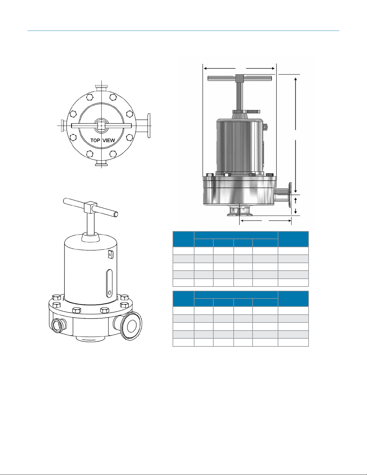
gauge port conFiguration options
3/4" Tri-C
@ 180°
(96-XXX-6L-180)
3/4" Tri-C @ 270°
(96-XXX-6L-270)
3/4" Tri-C @90°
(96-XXX-6L-90)
Outlet @ 0°
Std. (96-XXX-6L)
Inlet
Dimensions
D
A
Outlet
B
C
Ex. (96-XXX-6L-90)
Valve
Size
3/4" 3.29 8.00 1.50 5.70 18
1" 4.00 8.00 1.64 5.70 20
1-1/2" 4.21 10.50 2.53 7.25 40/28.7*
2" 5.34 17.50 2.96 9.50 90/66**
3" 5.34 18.00 3.46 9.50 98
Valve
Size
DN20 84 203 38,1 145 8,1
DN25 102 203 41,7 145 9,1
DN40 107 267 64,3 184 18/13*
DN50 136 445 75,2 241 41/30**
DN80 136 457 87,9 241 44,4
Based on US tri-clamp ends. Consult factory for DIN and ISO tri-clamp
end dimensions
* 40 lbs (18,1 kgs) std; 28.7 lbs (13 kgs) with aluminum
spring housing
** 90 lbs (40,7 kgs) std; 66 lbs (33 kgs) with aluminum
spring housing
sample speciFication
Dimensions (inches)
A B C D
Dimensions (mm)
A B C D
Weight
Lbs
Weight
Kgs
Stainless steel sanitary pressure regulator shall be made from ASME-SA479 barstock material, which
includes body and all wetted metal parts. Regulator shall be activated by FDA approved, USP Class
VI certied Jorlon diaphragm. Guiding of valve stem/plug shall be outside of the wetted, process areas
of valve internal, above diaphragm. Regulator shall be free of threads within wetted, process areas of
valve internal and shall be self draining when installed with inlet vertical and below valve assembly.
-5-
Page 6
— — —
Mark 96 SerieS Sanitary PreSSure regulatorS
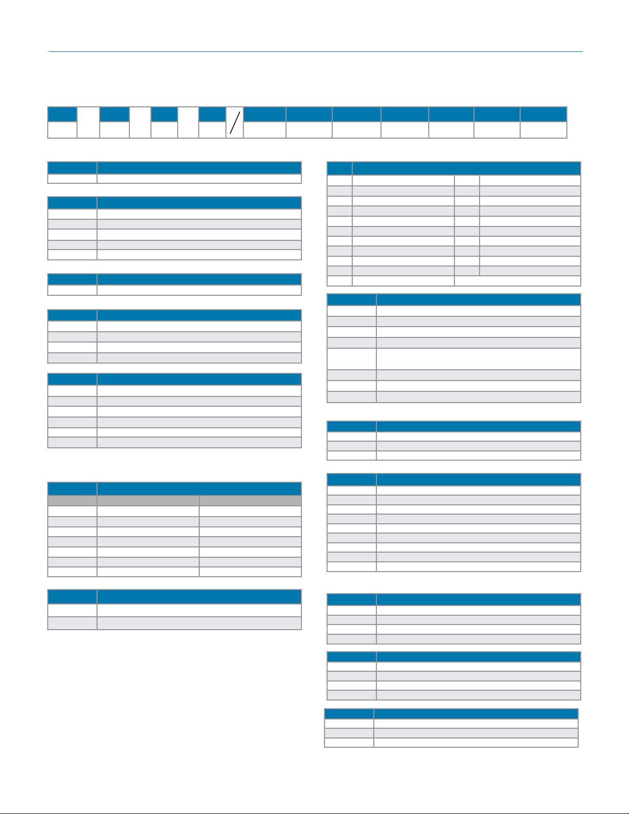
orDering schematic
1 & 2 3 & 4 5 & 6 7 & 8 9 & 10 11 & 12 13 & 14
1
96/0514/AB
96 Standard
Model
Size
075 3/4"
100 1"
150 1-1/2"
200 2"
300 3"
Material
6L 316L
Body Conguration
Leave blank for standard
90 3/4" Tri-Clamp F/Gauge @ 90°
180 3/4" Tri-Clamp F/Gauge @ 180°
270 3/4" Tri-Clamp F/Gauge @ 270°
1 Body Finish
A 20Ra (SFV5) Interior/63RMS Exterior (Std)
B 20Ra (SFV5) Interior/20Ra Exterior
C 8Ra Interior/63RMS Exterior*
D 20Ra (SFV5) Interior/8Ra Exterior
E 8Ra Interior/8Ra Exterior*
F 8Ra Interior/20Ra Exterior*
* Handle and all external surfaces meet spec per above. The adjusting screw is a threaded part and cannot be polished beyond 20Ra
2 Body Cv (Kv) See chart on page 2
Cv Kv
A 1.5 1,3
D 2.5 2,2
H 4.5 3,9
K 5.5 & 6.1 4,7 & 5,3
M 10.0 8,6
N 19.0 16,3
P 23.0 19,8
4 Trim – Cv (Kv) & Seat
A 1.5 (1,3) Hard Seat N 5.5 (4,7) Jorlon Seat
2 1.5 (1,3) Jorlon Seat P 10 (8,6) Hard Seat
B 2.5 (2,2) Hard Seat Q 10 (8,6) Teon Seat
C 2.5 (2,2) Teon Seat R 10 (8,6) Jorlon Seat
D 2.5 (2,2) Jorlon Seat S 19 (16,3) Hard Seat
H 4.5 (3,9) Hard Seat T 19 (16,3) Teon Seat
J 4.5 (3,9) Teon Seat U 19 (16,3) Jorlon Seat
K 4.5 (3,9) Jorlon Seat V 23 (19,8) Hard Seat
L 5.5 (4,7) Hard Seat W 23 (19,8) Teon Seat
M 5.5 (4,7) Teon Seat X 23 (19,8) Jorlon Seat
7 6.1 (5,3) Hard Seat
5 & 6 O-Ring/Diaphragm
BU Buna-N/SST Diaphragm
EE EPDM/EPDM Diaphragm
EP EPDM/SST Diaphragm
SL Silicone/SST Diaphragm
TS
Teon Encaps. Silicone/SST Diaphragm
(1-1/2" - 3" only)
TY Teon Encaps. Viton/Jorlon Diaphragm
TV Teon Encaps. Viton/SST Diaphragm
VT Viton/SST Diaphragm
7 Adjusting Screw Finish (Except Threads)
A Electro-polished (Standard)
B 20Ra (SFV5)
C 8Ra
8 Range PSI (Bar) see chart on page 2
A 3 - 8 (0,2 - 0,6)*
C 5 - 25 (0,3 - 1,7)
E 10 - 25 (0,7 - 1,7)
P 15 - 25 (1,0 - 1,7)
H 15 - 50 (1,0 - 3,4)
J 15 - 60 (1,0 - 4,1)
M 35 - 100 (2,4 - 6,9)
R 40 - 90 (2,8 - 6,2)
T 75 - 135 (5,2 - 9,3)
* Must use EPDM or Ultra-thin Jorlon diaphragm
3 Trim Finish
A 20Ra (Standard)
B 8Ra
9 & 10 Diaphragm
6L SST (all exterior)
EP EPDM (all exterior)
JL Jorlon (all exterior)
UJ Ultra-thin Jorlon (all exterior)
11 & 12 Actuator Finish/Type
AA Standard
BA 20Ra (SFV5) exterior
CA 8Ra exterior
DA Electro-polished for 2" & 3"
13 & 14 PED Compliance
00 Not required
FF CE Category 1
ZZ Non-standard
Steriflow Valve reserves the right to make revisions to its product, specifications, literature and related information without notice. Please visit our
website at www.steriflowvalve.com for the latest information on our products.
 Loading...