

Page 1
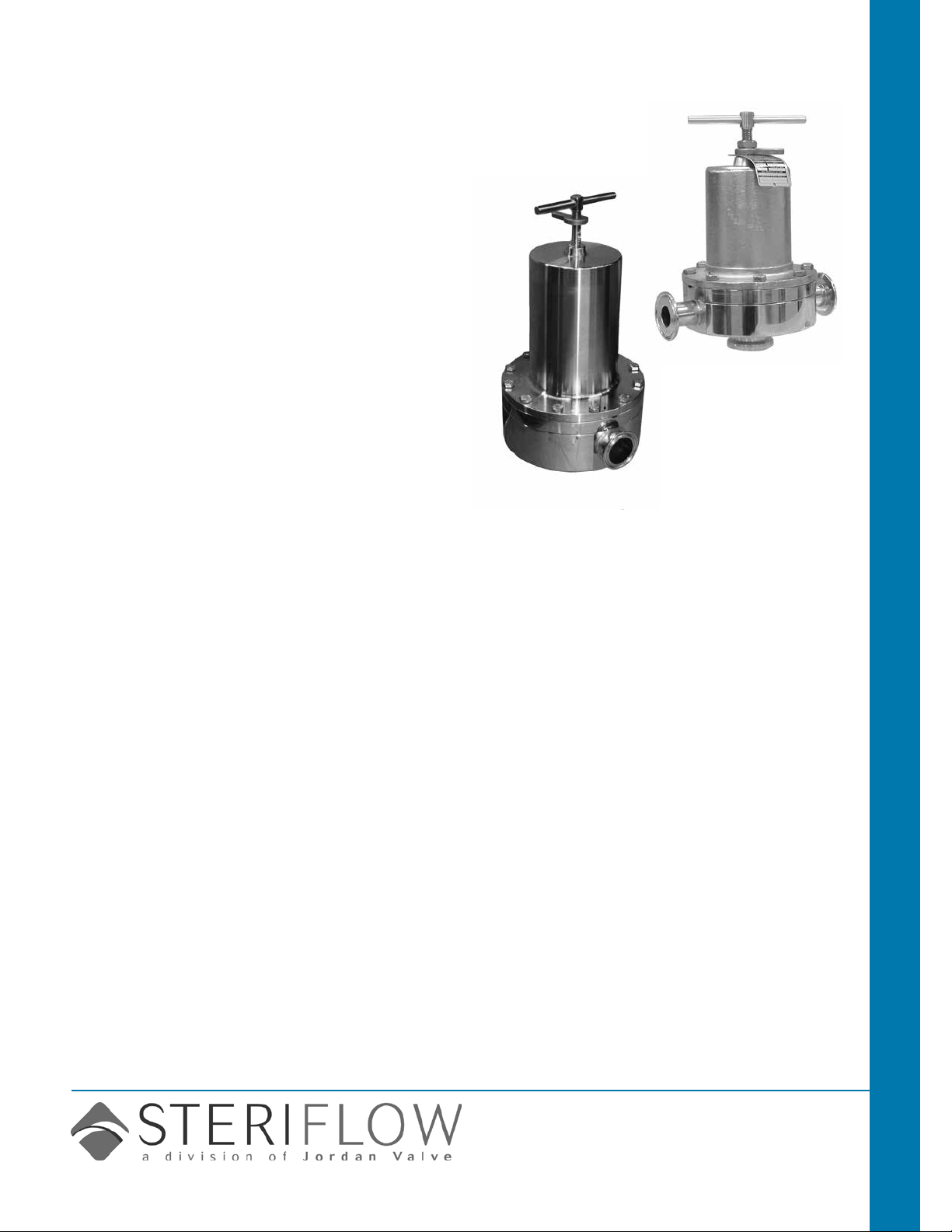
Mark 95 Series
Sanitary Back Pressure Regulators
The Mark 95 is available with a hard or soft seat
and a variety of diaphragm and o-ring materials,
making the valve well-suited for virtually any sterile
back pressure application.
The Mark95 operates by sensing the inlet pressure, or back pressure, beneath the diaphragm, as
ow enters from inlet port on the side. As the back
pressure exceeds the setpoint, the diaphragm force
compresses the range spring permitting the stem
to move from the seat toward the open position. As
the ow increases, the back pressure is relieved
and the spring and diaphragm relax, allowing the
stem to return to the normally closed position. If a
different set point is desired, a simple turn of the
adjusting screw will increase or decrease the setting to any set point within the range covered by the
regulator's spring.
CRN Registration Number Available
Sanitary Valves Mark 95 Sanitary Back Pressure Regulators
Features
• New! Optional integral gauge port
• CRN Registration Number Available
• Soft seat capability for ANSI Class VI shutoff
• No guiding surfaces in the uid – prevents particulate generation
• 100% 316L barstock body and trim
• Self-draining
• No threads to disassemble for cleaning
• Clean-in-Place, Steam-in-Place – dome fea-
tures spring arrangement to allow CIP/SIP
• Remote setpoint capability
• Lifetime warranty on Jorlon diaphragm
Documentation
The following documentation is shipped with each
order:
• Steriow Unicert
— Traceable Material Heat Number for body
and ferrules
— Certicate of Compliance to FDA and USP
Class VI
Certicate of Surface Finish
• Final Test Reports and Certicate of Origin
available upon request at time of order
available Finishes (mK95/mK95Ft)
Body
• Standard: 20 Ra µin (0,5 Ra µm) (ASME BPE
SF5) mechanical nish and electropolish on
inside wetted surfaces; machine nish and
electropolish on exterior.
• Optional: 20 Ra µin (0,5 Ra µm) SF5 mechani-
cal nish and electropolish on external surfaces;
8 Ra µin (0,2 Ra µm) nish on internal or external nishes and electropolish (Better than SF4)
Spring Housing and Handle
• Standard: machine nished 316SST,
electropolished
• Optional: 20 Ra µin (0,5 Ra µm) mechanical n-
ish and electropolish on external surfaces (SF5).
8 Ra µin (0,2 Ra µm) nish on external surfaces
on all sizes and electropolish. (Better than SF4)
Adjusting Screw
• Standard: 32Ra µin electropolished (Note:
adjusting screw is a threaded part)
• Optional: 20 Ra µin (0,5 Ra µm) mechanical
nish and electropolish nish (SF5)
Steriflow by Jordan Valve
3170 Wasson Road • Cincinnati, OH 45209
513.533.5600 • 800.543.7311 • 513.871.0105 (f)
sterifl[email protected] • www.steriflowvalve.com
Page 2
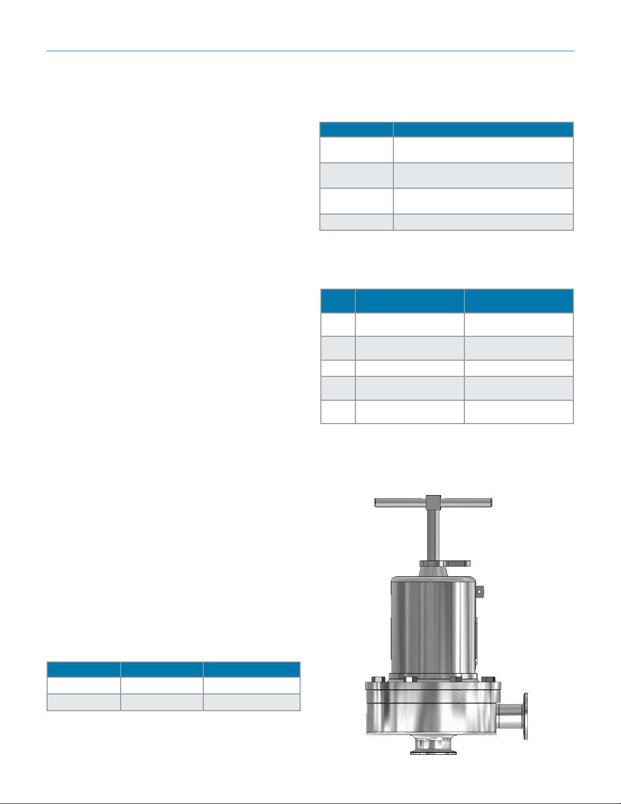
Mark 95 SerieS Sanitary Back PreSSure regulatorS
speciFications – o-ring Diaphragm
Sizes: 1/2" (DN15), 3/4" (DN20), 1" (DN25), 1-1/2"
(DN40), 2" (DN50), 3" (DN80)
End Connections
• Quick disconnect ttings (to match Tri-Clamp® tting)
• DIN/ISO sanitary connections
Body & Trim Materials: 316L Stainless Steel (ASTM
A47, S31603)
Seat Materials
• Standard hard seat – integral 316L SST seat
• Optional soft seat (for Cv 1.5, 1" size and above)
– Jorlon (FDA & USP Class VI) for steam and hot
uid service to 338°F (170°C)
– PEEK (FDA & USP Class VI) for steam and hot
uid service to 350° (177°C)
– PTFE to +252°F (122°C) continuous or 275°F
(135°C) intermittent [not to exceed 15 min. in a
one hour period] FDA, USP Class VI
Note: consult factory for 1/2" & 3/4" soft seat materials
Spring Housing Materials
• CF8M cast SST (1/2" – 1-1/2")
• Fabricated 316L SST (2" – 3")
Diaphragm Materials
• 316L SST
• EPDM/Nylon (to 275°F, 135°C), FDA only
• Jorlon (to 400°F, 204°C), FDA, USP Class VI
• Ulta-thin Jorlon (to 400°F, 204°C), FDA, USP
Class VI (for use with 3-8 range spring only)
O-Ring Materials
• EPDM (to 275°F, 135°C) - FDA, USP Class VI
• Buna-N (to 225°F, 107°C) - FDA
• Viton (to 400°F, 204°C) - FDA, USP Class VI
• Silicone (to 400°F, 204°C) - FDA, USP Class VI
• Teon-Encapsulated Viton (to 400°F, 204°C) -
FDA, USP Class VI)
• Teon-Encapsulated Silicone (to 400°F, 204°C) FDA, USP VI (1-1/2" - 3")
Set Point Spring Ranges
Valve Size Set Point Ranges, PSI (bar)
1/2", 3/4" & 1"
1-1/2"
2"
3" 15-25 (1,0-1,7) or 15-60 (1,0-4,1)
* Range available with elastomer or Ultra-thin Jorlon
diaphragm only. Maximum pressure drop 40 psi
3-8* (0,2-0,5), 5-30 (0,3-2,1),
15-50 (1,0-3,4), or 35-90 (2,4-6,2)
3-25* (0,2-1,7), 10-25 (0,7-1,7),
15-40 (1,0-2,8) or 35-85 (2,4-5,9)
5-25* (0,3-1,7), 10-25 (0,7-1,7)
or 15-60 (1,0-4,1)
.
Cv (Kv) Ratings:
Valve
Size
1/2",
3/4"**
1"**
1-1/2" 4.5 (3,9) or 10.0 (8,6) 4.5 (3,9) or 10.0 (8,6)
2"
3"
Metal Diaphragms
Cvs (Kvs)
0.5 (04,), 1.5 (1,3) 0.5 (04,), 1.5 (1,3)
1.5 (1,3), 3.0 (2,6) or
4.5 (3,9)
10.0 (8,6) or
19.0 (16,3)
10.0 (8,6) or
28.0 (24,1)
Elastomer Diaphragm
Cvs (Kvs)
1.5 (1,3), 3.0 (2,6) or
5.5 (4,7)
10.0 (8,6) or
19.0 (16,3)
10.0 (8,6) or
28.0 (24,1)
** Cv's limited when using the 3-8 range spring
Maximum Allowable Pressure Differential: 200 psi
(3-8 spring range has a max of 40 psi)
Shutoff: ANSI Class III hard seat or Class VI soft seat
Body Pressure Temperature Rating: (dependent
upon construction)
Valve Size PSIG @ 100°F PSIG @ 450°F
1/2", 3/4" & 1" 350 (24,1 bar) 250 (17,2 bar)
1-1/2" , 2" & 3" 200 (13,8 bar) 200 (13,8 bar)
Pressure on 1/2", 3/4" & 1" size limited to 225 psig (15,5 bar)
@ 100°F and 200 psig (13,8 bar) @ 400°F if using Ultra-thin
Jorlon diaphragm.
-2-
Page 3
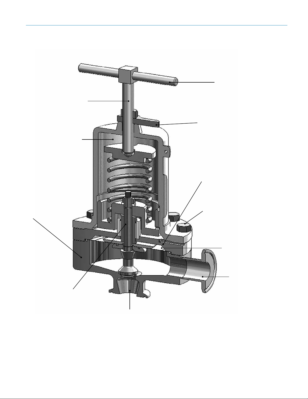
316 adjusting screw
316 Stainless Steel
spring housing
Mark 95 SerieS Sanitary Back PreSSure regulatorS
Features & beneFits
316 T-handle for easy
handling and setpoint
adjustment
Thumblock for securing
and retaining setpoint
100% barstock body
and trim, nish to
SFV5 standard; or
SFV4 optional
New! Optional Integral
Gauge Port. Orient inlet
gauge port 90°, 180°,
270° from inlet
Secure guiding
above diaphragm
area, not in seat/
orice, to eliminate
metal-to-metal particulate generation
No threads in contact with
media
Bolted bonnet for increased
safety and pressure/
temperature rating
Jorlon diaphragm provides
extremely long life - Lifetime Warranty
Self-draining design (in
this orientation)
applications
The MK95 is suitable for a variety of process and clean utility applications in the biopharmaceutical, semi-conductor, and food & beverage industries including: continuous circuit WFI pump deadhead diversion, bioreactor
agitator seal pressure maintenance, large volume ll back pressure release, and zero dead leg pressure relief.
-3-
Page 4
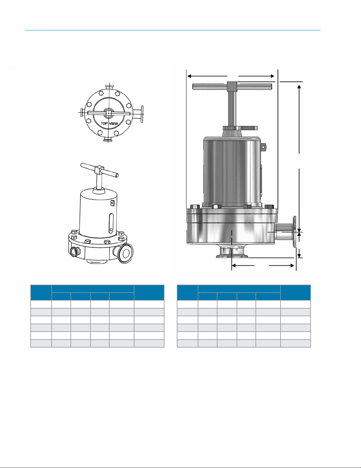
Mark 95 SerieS Sanitary Back PreSSure regulatorS
Dimensions
3/4" Tri-C
@ 270°
(95-XXX-6L-270)
D
3/4" Tri-C
@ 180°
(95-XXX-6L-180)
Example: (95-XXX-6L-90)
Inlet @ 0°
(95-XXX-6L)
3/4" Tri-C @ 90°
(95-XXX-6L-90)
B
Inlet
C
Outlet
A
Valve
Size
Dimensions (inches)
A B C D
Weight
Lbs
1/2" 3.29 8.00 1.37 5.70 18
3/4" 3.29 8.00 1.50 5.70 18
1" 4.00 8.00 1.64 5.70 20
1-1/2" 4.21 10.50 2.53 7.25 40
2" 5.34 17.50 2.96 9.50 90
3" 5.34 18.00 3.46 9.50 98
Valve
Size
DN15 84 203 35 145 8,1
DN20 84 203 38 145 8,1
DN25 102 203 42 145 9,1
DN40 107 267 64 184 18
DN50 136 445 75 241 41
DN80 136 457 88 241 44,4
Based on US tri-clamp ends. Consult factory for DIN and ISO tri-clamp
end dimensions
Dimensions (mm)
A B C D
Weight
Kgs
sample speciFication
Stainless steel sanitary back pressure regulator body and wetted components shall be made from
316L, ASTM A479, S31603 barstock material. Regulator shall be activated by FDA approved, USP
Class VI certied Jorlon diaphragm with lifetime guarantee. All guiding of valve stem/plug shall be out-
side of the wetted, process areas, above diaphragm. Regulator shall be free of threads within wetted,
process areas of valve internal and shall be self draining when installed with outlet vertical and below
valve assembly.
-4-
Page 5
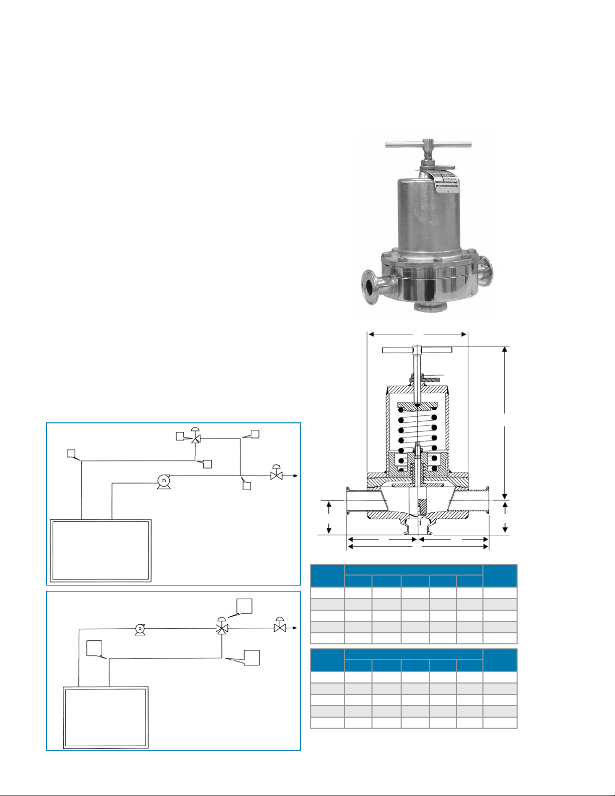
Mark 95FT Series
CRN Registration Number Available
Sanitary "Flow Through" Back Pressure Regulators
Starting with the features and benets associated with
the superior design of the Mark 95, Steriow Valve has
added a ow-through option that creates more application potential. The MK95FT can eliminate a portion of
the by-pass line components by allowing the back pressure regulating valve to be installed in the primary line
– not in the separated by-pass line.
The Mark 95FT is often found in liquid services such
as WFI loops, CIP lines and filling lines. The valve is
normally closed, allowing flow to pass straight through
to downstream users. When demand downstream is
reduced and pressure builds and reaches the setpoint,
the Mark 95FT will open to relieve and maintain constant pressure. This design allows for elimination of
pipe "T's" and elbows, reduction of weld joints, simplified by-pass piping and easier, quicker installation.
Due to the unobstructed flow path through the valve,
very little to no pressure loss through the valve can
be expected. This is a key reason the MK95FT can be
installed directly into the primary process piping.
D
A typical MK95 pump by-pass line
looks as follows:
2
WFI RESERVOIR
MK95FT solution:
2
1. MK95FT (3 welds for clamp
WFI RESERVOIR
2. 90° "L" elbow (2 welds)
3. 90° "L" elbow (2 welds)
1
3
1. MK95 (1 welded clamp
connection on inlet piping)
2. 90° "L" elbow (2 welds)
3. 90° "L" elbow (1-2 welds)
4. 90° "L" elbow (2 welds)
5. 180° "T" connector (3 welds)
connection in pipe)
4
5
1
3
OutletInlet
C
Valve
Size
By-pass
E
Dimensions (inches)
AA
A B C D E
Weight
Lbs
3/4" 3.29 8.50 1.50 5.70 6.58 19
1" 4.00 8.50 1.64 5.70 8.00 21
1-1/2" 4.24 10.5 2.53 7.25 8.48 41
2" 5.34 17.5 2.96 9.50 10.7 91
3" 5.34 18.0 3.46 9.50 10.7 99
Valve
Size
Dimensions (mm)
A B C D E
Weight
Kgs
DN20 84 216 38 145 168 8,6
DN25 102 216 42 145 203 9,5
DN40 108 267 64 184 214 19
DN50 136 445 75 241 271 41
DN80 136 457 88 241 271 45
Based on US tri-clamp ends. Consult factory for DIN and ISO
tri-clamp end dimensions
B
C
Page 6
Mark 95 SerieS Sanitary Back PreSSure regulatorS
— — —
95/0514/AB
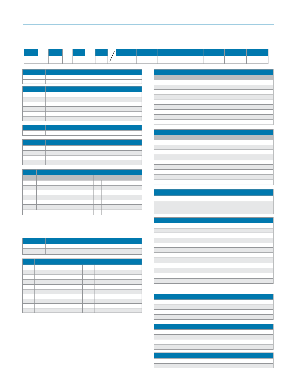
orDering schematic
1 & 2 3 & 4 5 & 6 7 & 8 9 & 10 11 & 12 13 & 14
1
95 Standard
Model
95FT Flow-Through
Size
050 1/2" (DN15)
075 3/4" (DN20)
100 1" (DN25)
150 1-1/2" (DN40)
200 2" (DN50)
300 3" (DN80)
Body Material
6L 316L
Body Conguration
Leave blank for standard
90 3/4" Tri-Clamp F/Gauge @ 90°
180 3/4" Tri-Clamp F/Gauge @ 180°
270 3/4" Tri-Clamp F/Gauge @ 270°
1 & 2 Body
Finish Cvs (Kvs)
20Ra Interior/63rms Exterior (Std) A 0.5 & 1.5 (0,5 & 1,3)
A
20Ra Interior/20Ra Exterior G 3.0 (2,6)
B
8Ra Interior/63rms Exterior* H 4.5 (3,9)
C
20Ra Interior/8Ra Exterior K 5.5 (4,7)
D
8Ra Interior/8Ra Exterior* M 10.0 (8,6)
E
8Ra Interior/20Ra Exterior* N 19.0 (16,3)
F
P 28.0 (24,1)
* Handle and all external surfaces meet spec per above. The adjusting screw is a threaded part and cannot be polished beyond 20Ra
Note: These valves are all tri-clamp end connections. Consult factory
for other options.
3 Trim Finish
A 20Ra (Standard)
B 8Ra
4 Trim – Cv (Kv) & Seat
5 0.5 (0,4) Hard Seat N 5.5 (4,7) Jorlon Seat
A 1.5 (1,3) Hard Seat P 10 (8,6) Hard Seat
E 3.0 (2,6) Hard Seat Q 10 (8,6) Teon Seat
F 3.0 (2,6) Teon Seat R 10 (8,6) Jorlon Seat
G 3.0 (2,6) Jorlon Seat S 19 (16,3) Hard Seat
H 4.5 (3,9) Hard Seat T 19 (16,3) Teon Seat
J 4.5 (3,9) Teon Seat U 19 (16,3) Jorlon Seat
K 4.5 (3,9) Jorlon Seat V 28 (24.1) Hard Seat
L 5.5 (4,7) Hard Seat W 28 (24,1) Teon Seat
M 5.5 (4,7) Teon Seat X 28 (24,1) Jorlon Seat
5 & 6 O-Ring/Diaphragm
Cv 0.5 thru 3.0
BS Buna/SST Dia.
EL EPDM/EPDM Dia.
ES EPDM/SST Dia.
SS Silicone/SST Dia.
TL Teon Encap. Silicone/SST Dia. (1-1/2" - 3")
TG Teon Encap. Viton/Jorlon Dia.
TE Teon Encap. Viton/SST Dia.
VS Viton/SST Dia.
ZZ Non-standard
5 & 6 O-Ring/Diaphragm
Cv > 3.0
BU Buna/SST Dia.
EE EPDM/EPDM Dia.
EP EPDM/SST Dia.
SL Silicone/SST Dia.
TS Teon Encap. Silicone/SST Dia. (1-1/2" - 3")
TY Teon Encap. Viton/Jorlon Dia.
TV Teon Encap. Viton/SST Dia.
VT Viton/SST Dia.
ZZ Non-standard
7 Adjusting Screw Finish (Except Threads)
A Electro-polished (Standard)
B 20Ra (SFV5)
C 8Ra
8 Range PSI (Bar)
A 3 - 8 (0,2 - 0,6)*
B 3 - 25 (0,3 - 1,7)*
D 5 - 30 (0,3 - 2,1)
E 10 - 25 (0,7 - 1,7)
F 5 - 25 (0,3 - 1,7)/Elas. Diaphragm
P 15 - 25 (1,0 - 1,7)
G 15 - 40 (1,0 - 2,8)
H 15 - 50 (1,0 - 3,4)
J 15 - 60 (1,0 - 4,1)
K 35 - 85 (2,4 - 5,9)
L 35 - 90 (2,4 - 6,2)
Q 50 - 105 (3,4 - 7,2)
* Must use EPDM or Ultra-thin Jorlon diaphragm
9 & 10 Diaphragm
6L SST (all exterior)
EP EPDM (all exterior)
JL Jorlon (all exterior)
UJ Ultra-thin Jorlon (all exterior)
11 & 12 Actuator Finish/Type
AA Standard
BA 20Ra (SFV5) exterior
CA 8Ra exterior
DA Electro-polished for 2" & 3"
13 & 14 PED Compliance
00 Not Required
0G SEP/PED Compliant
 Loading...