

Page 1
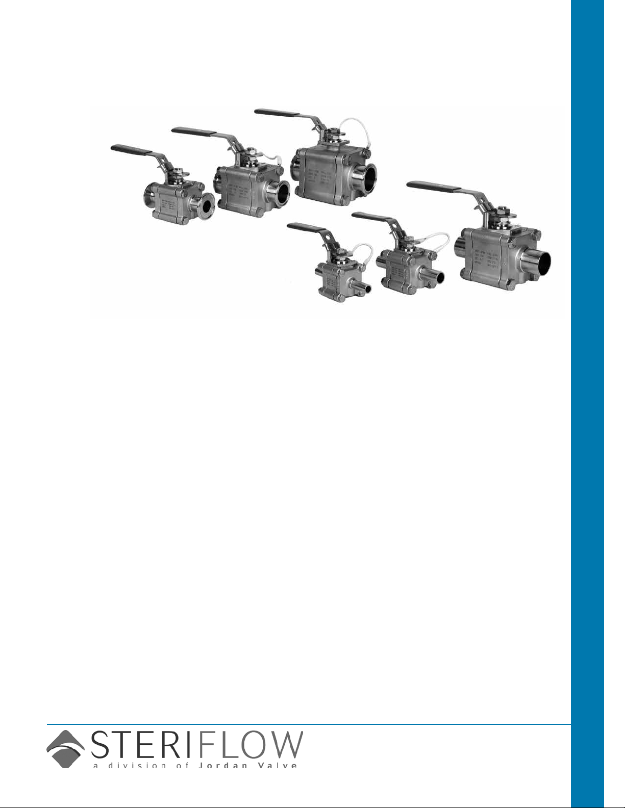
Mark 9020 Series
CRN Registration Number Available
Sanitary Ball Valves
The Mark 9020 Series ball valves take ASME BPE
guidelines to heart. This valve was designed from
the beginning to meet every aspect of ASME BPE
2009. From the materials chosen for seats and seals
to the nal marking and documentation, you can
trust the Steriow name.
Sanitary Valves Mark 9020 Sanitary Ball Valves
New: Optional Integral bottom
condensate drain.
See pages 9 & 10
Features
• Traceable Industry grade high density 316L
body, ball, stem and end caps with <3% ferrite
standard, 1% optional
• Certied TFM 1600 body seal, seat, thrust
washer, and packing material meet:
— FDA 21 CFR 177
— Final form materials also certied to meet
USP <88> Class VI (in-vivo), and USP <87>
(in-vitro) testing requirements
• Documented surface nish on all wettable components is SF1 (20 Ra µin (.5 Ra µm) Mechanical Polish), SF4 (15 Ra µin (.4 Ra µm) mechanical/electropolish optional)
• Ball porting has identical ID as inlet/outlet tubing
to prevent holdup
• Pressure ratings to 1000 psig @ 100°F
• Anti-blowout stem design
• Tongue & groove body seal to insure gasket
containment and precise alignment regardless of
vibration
• Tri-clamp ends, extended tube weld ends, or
both available on all sizes
• Available as manual or actuated (pneumatic/
electric) valve
• ISO 5211 actuator mounting ange direct on
body, or on stem extensions
• Optional cavity ller seats available for non-BPE
applications
• Optional condensate drain and purge ports
• Stem grounding standard
Documentation
The following documentation is shipped with
each order:
• Steriow Unicert
— Certicate of Material compliance with
Traceable MTR's
— Certicate of Compliance to FDA and
USP <88> Class VI and USP <87>
— Certicate of Compliance to Surface
Finish
• Final Test Reports and Certicate of Ori-
gin available upon request at time of order
applications
• Biopharmaceutical, Pharmaceutical Clean
Steam, Condensate, or CIP
• Biopharmaceutical, Pharmaceutical Clean
Air and Gas
• Food and Beverage
• Fine and Specialty chemicals
• Any viscous media or other application
where inline valve cleaning or remove-for-
cleaning access is desired
Steriflow by Jordan Valve
3170 Wasson Road • Cincinnati, OH 45209
513.533.5600 • 800.543.7311 • 513.871.0105 (f)
sterifl[email protected] • www.steriflowvalve.com
Page 2

Mark 9020 SerieS Sanitary Ball ValVeS
sample speciFications
Mark 9020 Series (1/2" – 4") Investment Cast two-way, three piece sanitary ball valve, shall be designed,
manufactured, marked, and documented per ASME BPE-2009.
Body seal, seat, thrust washer, and packing shall be manufactured from FDA 21 CFR 177 acceptable TFM
1600, which has been tested in nal form to meet the requirements of USP Chapter 88 Class VI (in-vivo) and
USP Chapter 87 (in-vitro).
Body, ball, and end caps shall be manufactured from ASTM A351 Gr. CF3M 316L with ferrite controlled to
<3% (<1% optional).
Internal surface nish shall be SF1, 20Ra mechanical polish, or optional to SF4, 15 Ra mechanical polish with
electropolish.
Mounting ange on body and stem extensions shall be designed to ISO 5211 to facilitate actuator attach-
ment.
Valves shall not require disassembly for welding and shall be repairable inline.
Maximum working pressure shall be 1000 psi to full vacuum at 100°F for 1/2" through 2" design, 720 psi to
full vacuum for 2-1/2" through 4" sizes.
Weld end ttings or ferrules to match sanitary tubing connections. Body bolts and nuts to be 304 or better
strain-hardened with minimum tensile strength of 100,000 psi.
®
Stem packing shall be live loaded TFM
V-rings to compensate for pressure and thermal cycles and for wear,
to insure a positive seal against process leaks.
Steriow model series Mark 9020 size, material, seat/stem extension, ends, manual/automated, actuator
accessories, fail position.
-2-
Page 3
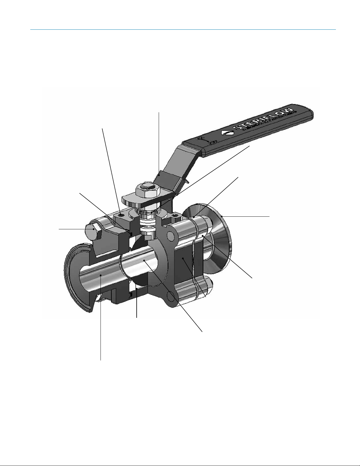
ISO 5211 actuator
mounting pad
Tongue and groove
body seal for gasket
containment and
precise alignment of
end caps, while allow-
ing inline repairability
Mark 9020 SerieS Sanitary Ball ValVeS
Features & BeneFits – 1/2" – 1-1/2"
Standard locking handle sleeve with body
tab allows secure lockout on all models
Live loaded TFM 1600 packing
Enclosed body bolts (1/2" – 1")
(1-1/2" has exposed body bolts)
Adjustable
extra strength
high grade
stainless
steel bolting
for dependable service
at elevated
pressure
FDA and USP <88>
(Class VI), and USP
<87> certied TFM
1600 seats and seals
standard
ASME BPE 2009
SF1(20 Ra) mechani-
cally polished internal
surfaces standard SF4
(15 Ra with electropolish
optional)
Tri-clamp end (shown),
extended tube weld
ends or mixed ends
available
316L <3% Ferrite standard,
<1% optional
Optional purge or
drain ports available
Bore matches sanitary
tubing ID
ART0956
-3-
Page 4
24
22
Mark 9020 SerieS Sanitary Ball ValVeS
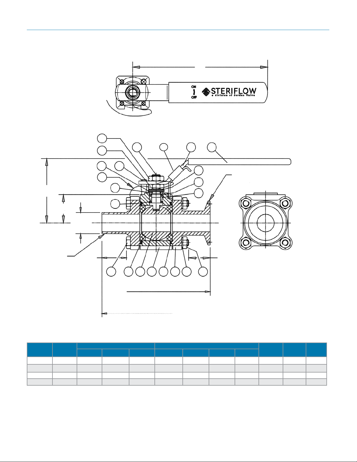
Dimensions (1/2" through 1-1/2")
D
5
39
19
21
C
Tube ends
ART0948-1
29
H
38
15
13
33
30
32
14
Tri-clamp
end
ØR2
F2
3736911141235
F1
B1
Tri-Clamp ends
B2
Tube ends
Inches
Size Port
Tri-Clamp Ends Tube Ends
B1 F1 Wt, Lb B2 F2 R2 Wt. Lb
D C H
1/2" 0.37 3.58 0.51 2.0 4.94 1.19 0.50 1.9 5.23 3.73 1.22
3/4" 0.63 4.25 0.73 3.1 5.29 1.25 0.75 3.0 5.23 2.91 1.38
1" 0.87 5.15 1.00 4.6 5.74 1.25 1.00 4.4 6.76 3.22 1.50
1-1/2" 1.37 5.91 0.66 9.0 6.51 0.96 1.50 8.9 8.04 3.84 1.92
-4-
Page 5
Mark 9020 SerieS Sanitary Ball ValVeS
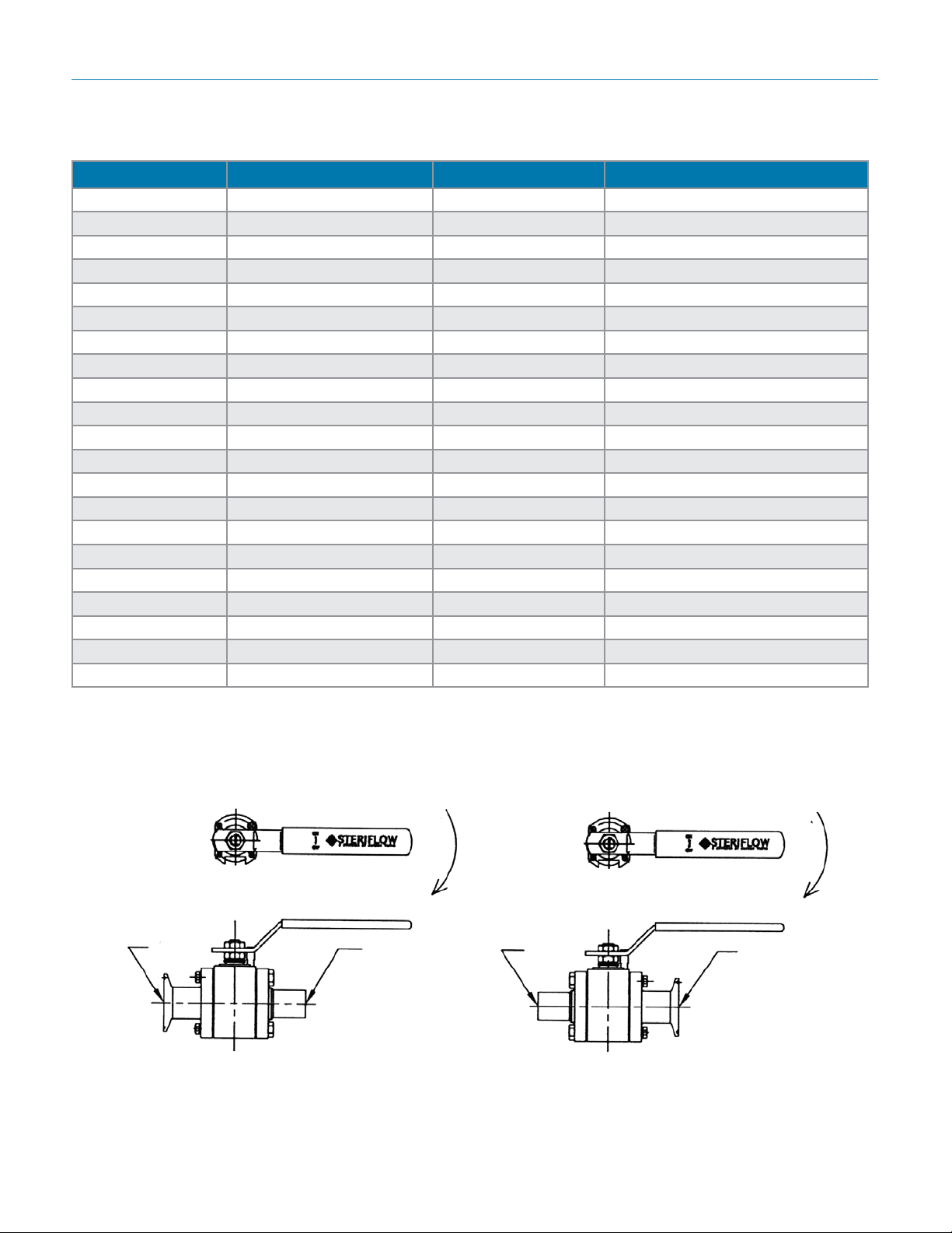
speciFications (1/2" through 1-1/2")
Item Part Name Quantity Material
1 Body 1 ASTM A351 Gr. CF3M, 316L
4 Ball 1 ASTM A351 Gr. CF3M
5 Stem 1 316L SS Bar
9 End Cap 2 ASTM A351 Gr. CF3M
11 Body Seal 2 TFM1600
12 Seat 2 TFM1600
13 Thrust Washer, Stem 1 TFM1600
14 Packing, Stem 1 Set TFM1600
15 Gland, Packing 1 AISI 304 SS
19 Handle 1 AISI 304 SS
21 Cover, Handle 1 Vinyl
22 Nut, Gland 1 AISI 304 SS
24 Nut, Handle 1 AISI 304 S
29 Belleville Washer 2 AISI 301 SS
30 Lock Tab Washer 1 AISI 304 SS
32 Thrust Washer, Packing 1 TFM1600
33 Stop Pin, Handle 1 AISI 304 SS
35 Bolt, Body 4 AISI 304 SS
36 Lock Washer, Body Bolt 4 AISI 304 SS
37 Nut, Body Bolt 4 AISI 304 SS
38 Grounding Cable 1 Braided Copper/Vinyl
nD arrangements & orDering coDes For unequal enDs
e
Clamp
Clamp x Tube
(Ordering Codes C & F)
Handle Open
Tube
Close
-5-
Tube
Tube x Clamp
(Ordering Codes G & H)
Handle Open
Clamp
Close
Page 6
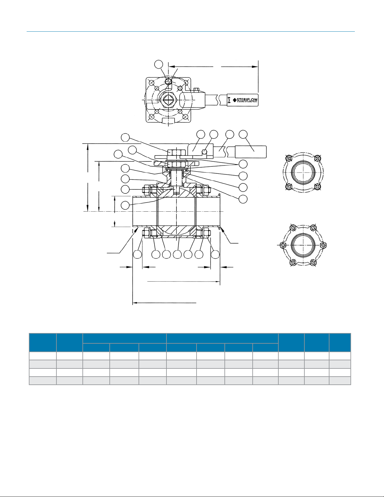
Mark 9020 SerieS Sanitary Ball ValVeS
Dimensions (2" through 4")
C
H
Tube End
30
ØR2
24
15
13
33
2-1/2" – 4"
D
21192018
22
29
38
5
32
14
2" ~ 2-1/2"
4
Tri-Clamp
35
3726111129
End
ART0949
F2
B1
F1
3" ~ 4"
(Tri-Clamp Ends)
B2
(Tube Ends)
Inches
Size Port
Tri-Clamp Ends Tube Ends
D C H
B1 F1 Wt, Lb B2 F2 R2 Wt. Lb
2" 1.87 6.53 0.75 10.2 6.87 1.04 2.00 10.0 8.0 4.9 3.25
2-1/2" 2.37 8.00 0.72 19.2 8.75 1.30 2.50 19.7 14.3 5.8 4.25
3" 2.87 9.19 1.09 28.4 9.25 1.06 3.00 27.0 14.3 6.0 4.56
4" 3.84 10.23 1.16 50.0 10.21 1.15 4.00 48.0 15.7 7.7 6.10
-6-
Page 7
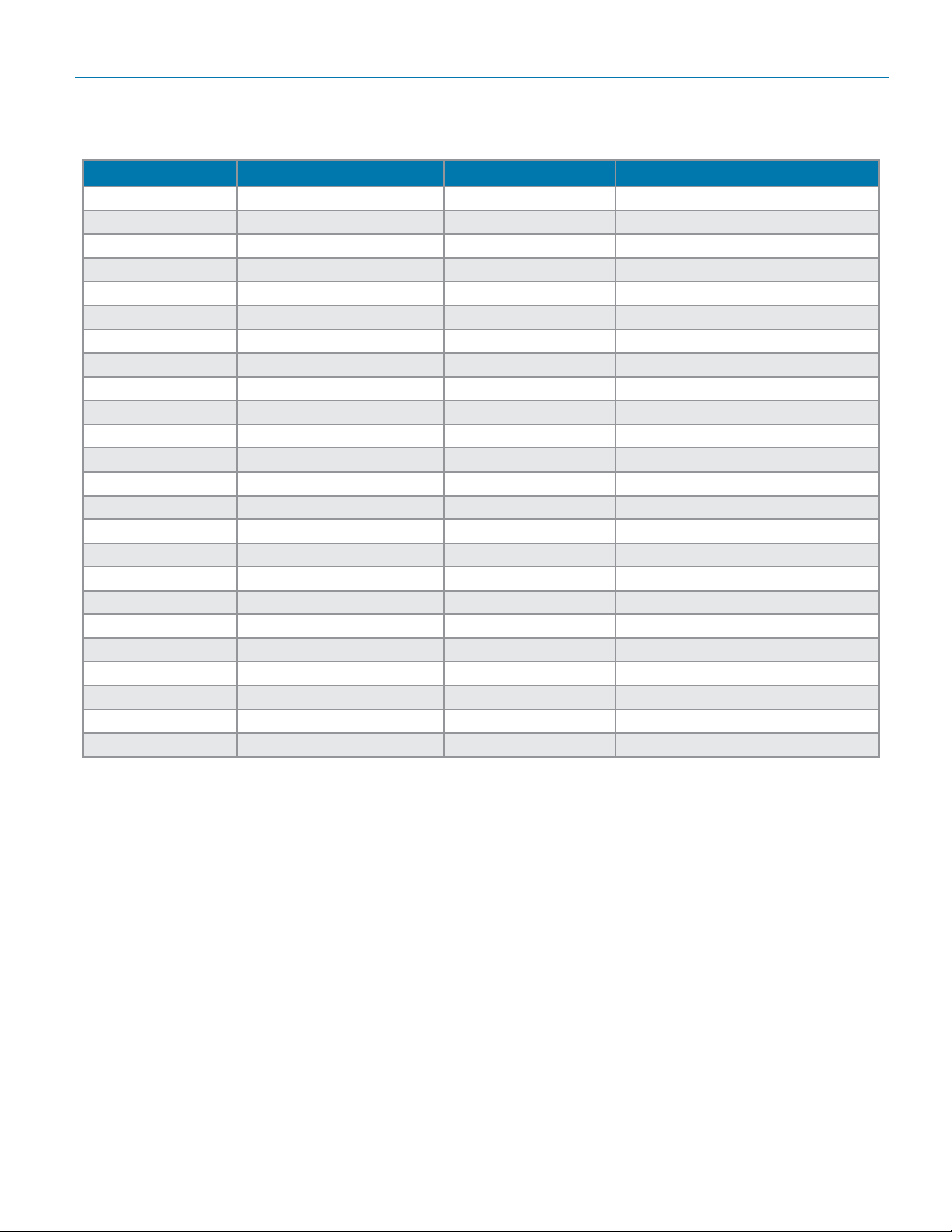
Mark 9020 SerieS Sanitary Ball ValVeS
speciFications (2" through 4")
Item Part Name Quantity Material
1 Body 1 ASTM A351 Gr. CF3M
4 Ball 1 ASTM A351 Gr. CF3M
5 Stem 1 316L SS Bar
9 End Cap 2 ASTM A351 Gr. CF3M
11 Body Seal 2 TFM1600
12 Seat 2 TFM1600
13 Thrust Washer, Stem 1 TFM1600
14 Packing, Stem 1 Set TFM1600
15 Gland, Packing 1 AISI 304 SS
18 Adaptor, Handle 1 AISI 304 SS
19 Handle 1 AISI 304 SS
20 Bolt, Handle 1 AISI 304 SS
21 Cover, Handle 1 Vinyl
22 Nut, Gland 1 AISI 304 SS
24 Nut, Handle 1 AISI 304 SS
29 Belleville Washer 2 AISI 304 SS
30 Lock Tab Washer 1 AISI 301 SS
32 Thrust Washer, Packing 1 TFM 1600
33 Stop Pin, Handle 1 AISI 304 SS
35 Stud, Body 4 ~ 6 AISI 304 SS
36 Lock Washer, Body Bolt 8 ~ 12 AISI 304 SS
37 Nut, Body Bolt 8 ~ 12 AISI 304 SS
38 Grounding Spring 1 AISI 304 SS
39 Locking Sleeve 1 AISI 304 SS
-7-
Page 8
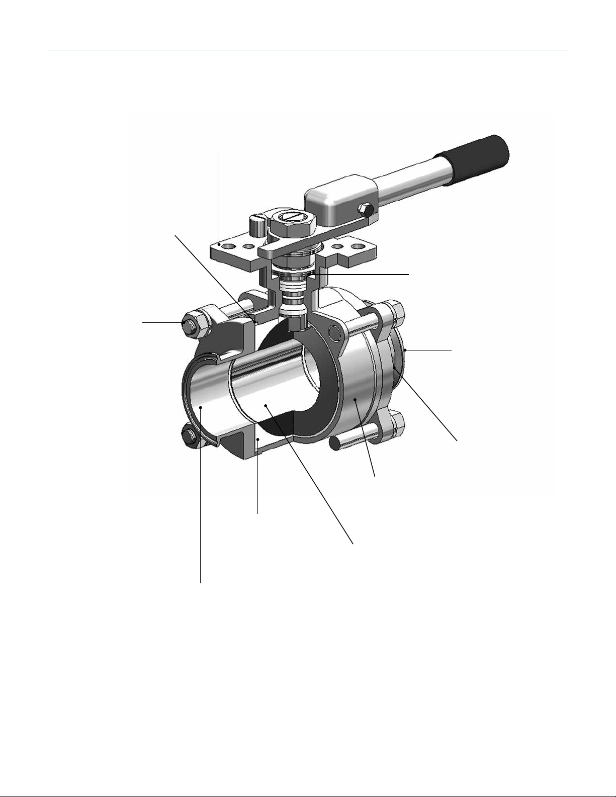
ISO 5211 direct mount
actuator pad
Tongue and groove body
seal for gasket containment
and precise alignment of
end caps while allowing
inline repairability
Adjustable extra
strength high grade
bolting standard for
dependable
service at elevated
pressure and vibration
Mark 9020 SerieS Sanitary Ball ValVeS
Features & BeneFits – 2" – 4"
Live loaded TFM 1600
packing
Tri-clamp end (shown),
extended tube weld
ends or mixed ends
available
ART0958
FDA and USP <88>
(Class VI), and USP
<87> TFM 1600 seats
and seals standard
ASME BPE 2007 SF1(20 Ra) mechanically polished internal surfaces,
standard, SF4 (15 Ra with electropolish optional)
316L <3% Ferrite standard,
<1% optional
Optional purge or
drain ports available
Bore matches sanitary tubing ID
-8-
Page 9
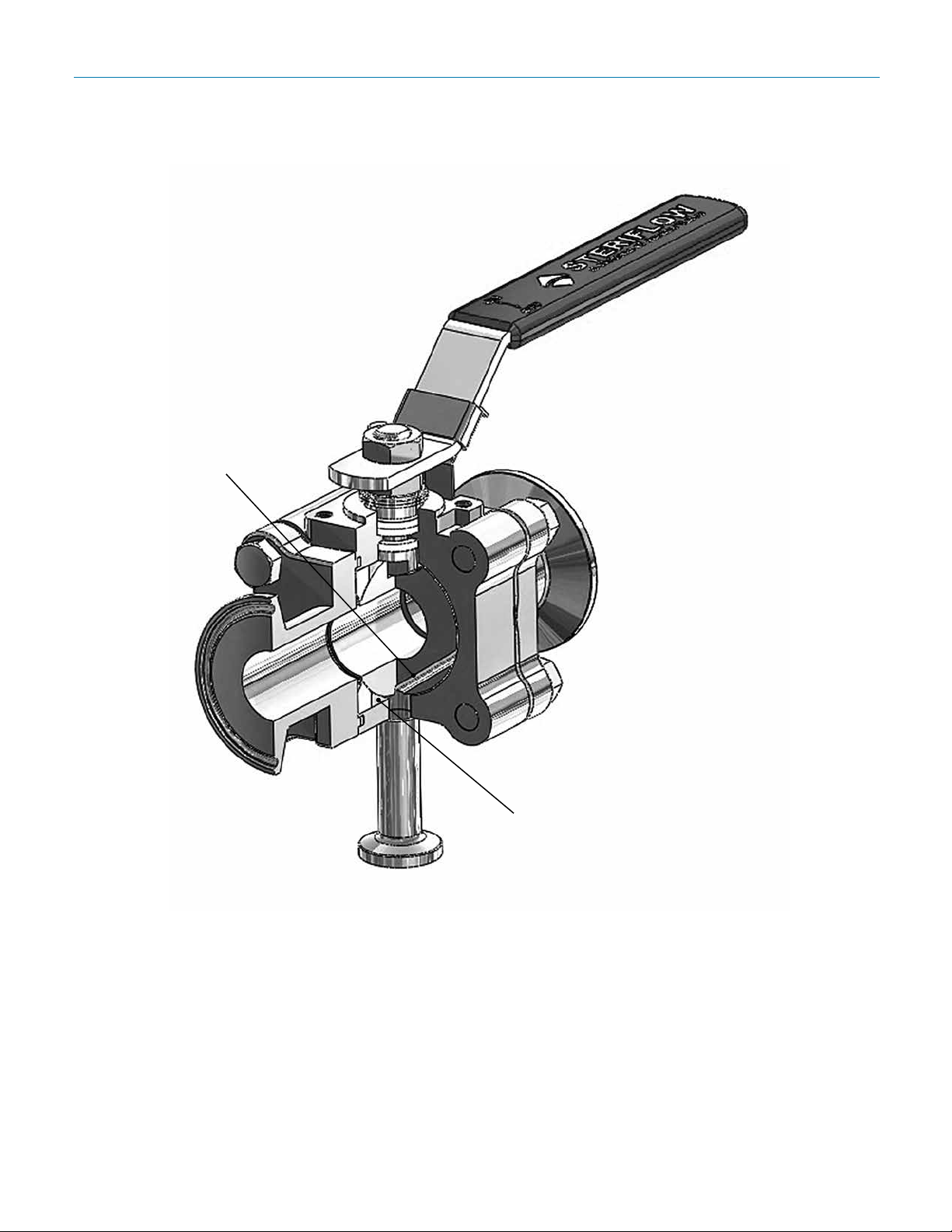
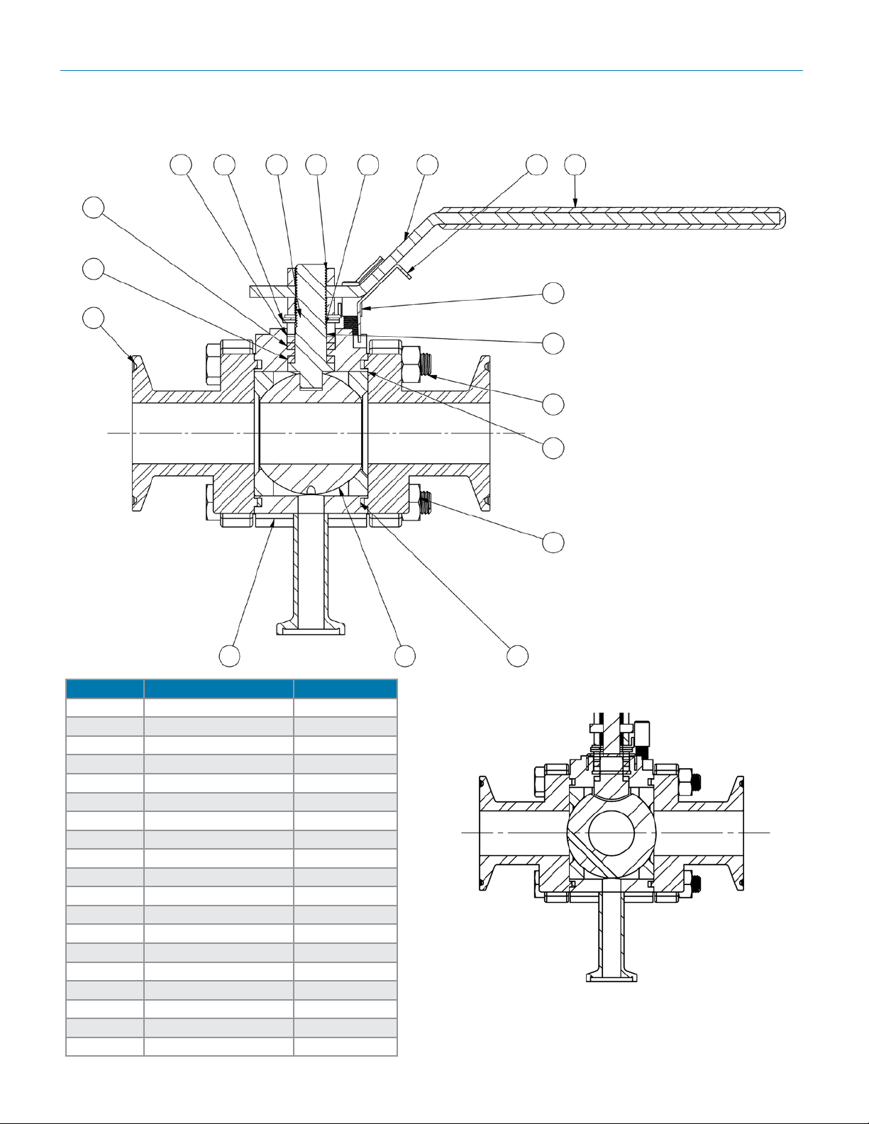
Features & BeneFits – conDensate Drain option
Unique condensate drain option
directs upstream clean steam
condensate, or trapped liquids in the
body cavity to drain.
When the valve is in the closed
position, this port directs clean
steam condensate from the closed
inlet side of the ball to drain,
preventing liquid backup. (Also see
next page)
Mark 9020 SerieS Sanitary Ball ValVeS
-9-
1/2" Tri-clampTM condensate drain
removes condensate or liquids from
the body cavity surrounding the ball.
It also insures complete sterilization
of the body cavity.
Page 10
Mark 9020 SerieS Sanitary Ball ValVeS
conDensate Drain option (BoDy orDer coDes Dl anD DF)
10
11
13
4
7
191631514
18
17
12
8
5
Open Position
9
1 2 6
Item No. Description Quantity
1 Body 1
2 Ball 1
3 Stem 1
4 Thrust Washer 1
5 Seat 2
6 Body SEal 2
7 Cap 2
8 Body Bolt 4
9 Bolt Nut 4
10 Stem Packing 2
11 Follower Washer 1
12 Gland Bush 1
13 Bellville Washer 2
14 Tab Washer 1
15 Stem Nut 2
16 Handle 1
17 Pin 1
18 Handle Cover 1
19 Lock 1
Closed/Vented Position
-10-
Page 11
Mark 9020 SerieS Sanitary Ball ValVeS
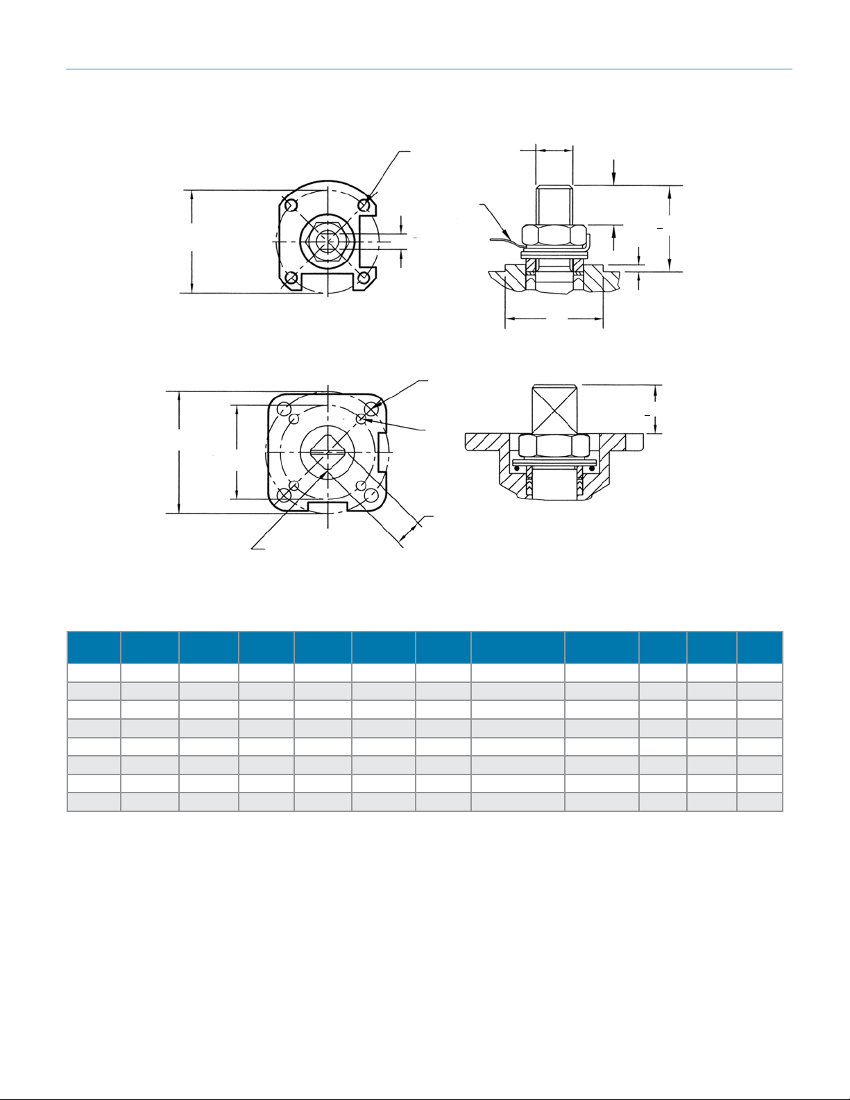
actuator mounting Dimensions
ART0950
C (B.C.)
C2 (B.C.)
C1 (B.C.)
ØK
Stem Thread
D
(Thread)
Ground
Wire
G Flats
1/2" ~ 1-1/2"
ØD2
ØD1
G Sq.
2" ~ 4"
ØK
Stem
Thread
M
L +0.030
0.08
N
L +0.030
Inches
Size
NPS
1/2" F03 1.42 M5 — — — 0.258 / 0.254 0.38-24 0.67 0.30 0.98
3/4" F03 1.42 M5 — — — 0.258 / 0.254 0.38-24 0.73 0.34 0.98
1" F04 1.65 M5 — — — 0.317 / 0.313 0.44-20 1.00 0.40 1.18
1-1/2" F05 1.97 M6 — — — 0.384 / 0.380 M14x1.4 1.26 0.58 1.38
2" F05 1.97 0.276 F07 2.76 0.354 0.549 / 0.545 0.69-10 0.76 — —
2-1/2" F07 2.76 0.354 F10 4.02 0.433 0.671 / 0.677 0.88-14 1.01 — —
3" F07 2.76 0.354 F10 4.02 0.433 0.671 / 0.677 0.88-14 1.01 — —
4" — — — F12 4.92 0.512 0.868 / 0.864 1.12-12 1.84 — —
ISO
Pattern
C1
(B.C.)
D1
ISO
Pattern
C2 (B.C.) D2
G
Flats or Sq.KStem Thd.
L M N
-11-
Page 12
Mark 9020 SerieS Sanitary Ball ValVeS
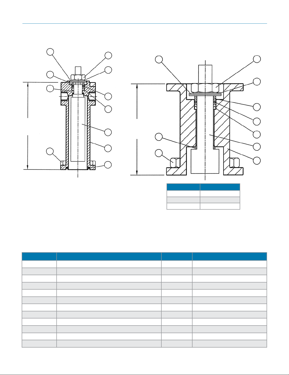
stem extension Dimensions
3.94"
(100 mm)
ART0953
52
51
45
50
1/2" ~ 1-1/2"
54
53
47
46
41
40
48
52
A
45
50
Size A
2-1/2" 3.94 (100mm)
2-1/2" ~ 4"
2" 3.94 (100mm)
3" 3.94 (100mm)
54
53
51
47
46
41
40
Notes:
1. Handle parts from valve.
2. Handle length and actuator mounting dimensions same as top of valve.
3. Add stem extension height "D" above to valve heights for heights of valve with stem extension.
Item Part Name Quantity Material
40 Bonnet 1 ASTM A351 Gr. CF3M
41 Stem, Extension 1 AISI 316L SS
45 Thrust Washer, Ext. Stem 1 AISI 316L SS
46 Packing, Ext. Stem 1 Set TFM 1600
47 Thrust Washer, Ext. Stem Packing 1 TFM 1600
48 Seal, Bonnet (1/2" ~ 1-1/2") 1 PTFE
50 Bolt, Bonnet 4 AISI 304 SS
51 Gland, Ext. Stem Packing 1 TFM 1600
52 Belleville Washer, Ext. Stem 2 TFM 1600
53 Tab Lock Washer, Ext. Stem 1 AISI 304 SS
54 Nut, Ext. Stem Packing 1 AISI 304 SS
55 Grounding Cable 1/2" - 1-1/2" only (Not Shown) 1 Braided Copper/Vinyl
-12-
Page 13
Mark 9020 SerieS Sanitary Ball ValVeS
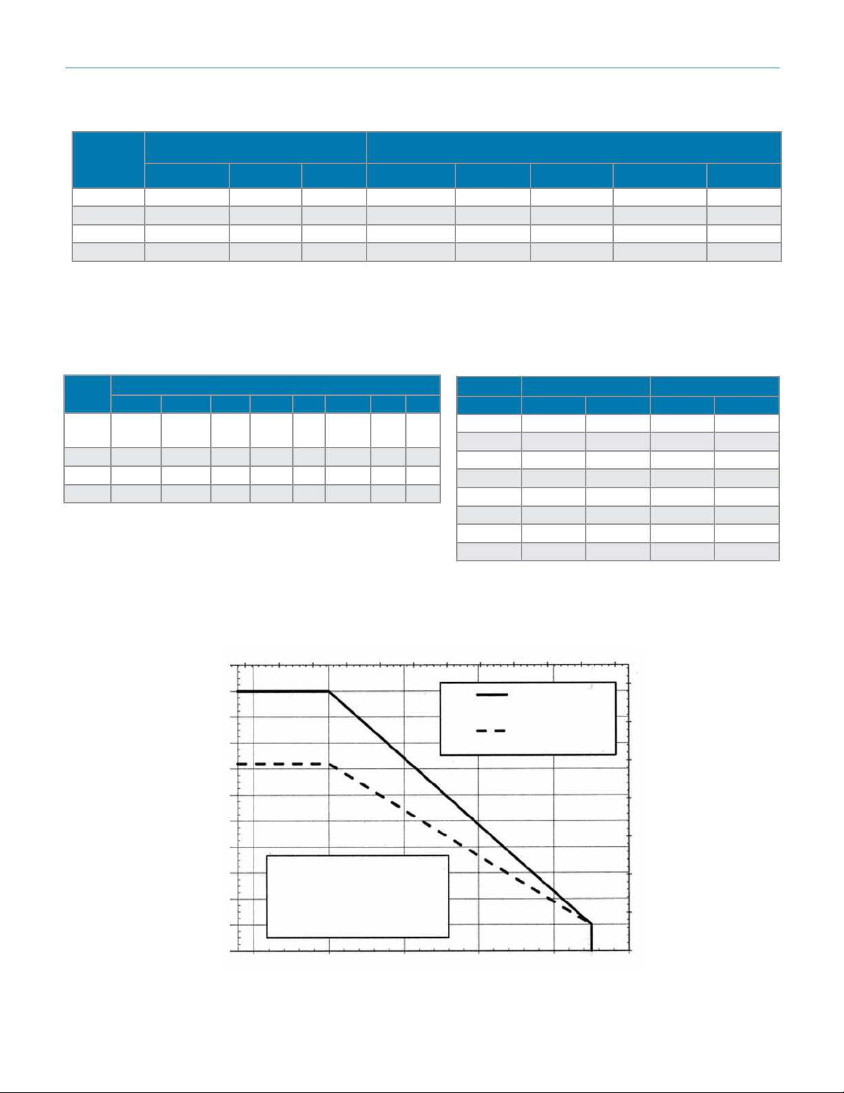
tri clamp pressure - temperature ratings
Temp °F
Pressure Rating, psi
13MHP Tri-Clamp (2 bolt)
A13MHM Tri-Clamp (2-Segment Hinged, Wing Nut)
Pressure Rating, psi
1/2"~2" 2-1/2"~3" 4" 1/2"~1-1/2" 2" 2-1/2" 3" 4"
-20 1000 720 720 500 450 400 350 300
0 1000 720 720 500 450 400 350 300
75 1000 720 720 500 450 400 350 300
250 1000 720 600 300 250 200 175 150
• Tri-Clamp gasket material maximum temperatures: Buna-N, PTFE – 200°F; EPDM – 300°F; Viton — 400°F;
Silicon — 450°F
• Pressure ratings based on tri-clamp and maximum pressure rating for product.
tuBe pressure - temperature ratings
Temp
°F
-20 to
+300
350 >1000 >1000 1000 1000 720 610 510 485
400 >1000 >1000 1000 995 720 590 480 470
450 >1000 >1000 1000 960 715 570 470 450
Tube ratings based on ASME B31.3 – 2002 for 316L tubing
and on maximum pressure rating for the valve
Pressure Rating, 2" ~ 4" Tube End, psi
1/2" 3/4" 1" 1-1/2" 2" 2-1/2" 3" 4"
>1000 >1000 1000 1000 720 695 525 505
technical inFormation
Size Operating Torque* Flow Coefcient
NPS in-lb N.m Cv Kv
1/2" 39 4,4 8 6,9
3/4" 95 10,7 30 26
1" 148 16,7 65 56
1-1/2" 338 38 190 163
2" 651 74 435 374
2-1/2" 797 90 720 619
3" 974 110 1120 963
4" 1328 150 2100 1806
* TFM 1600 seats, maximum differential pressure
1100
1000
900
800
700
600
500
Pressure, psi
400
300
200
100
0
pressure - temperature chart
Temperature °C
-25 0 25 50 75 100 125 150 175 200 225 250
1/2"~2"
2-1/2"~4"
Graph shows body center rating.
Clamp ttings or tube ends may
have lower allowable pressure
and temperature values than
center section
0 100 200 300 400 500
Temperature °F
70
60
50
40
30
20
10
0
Pressure, bar
-13-
Page 14
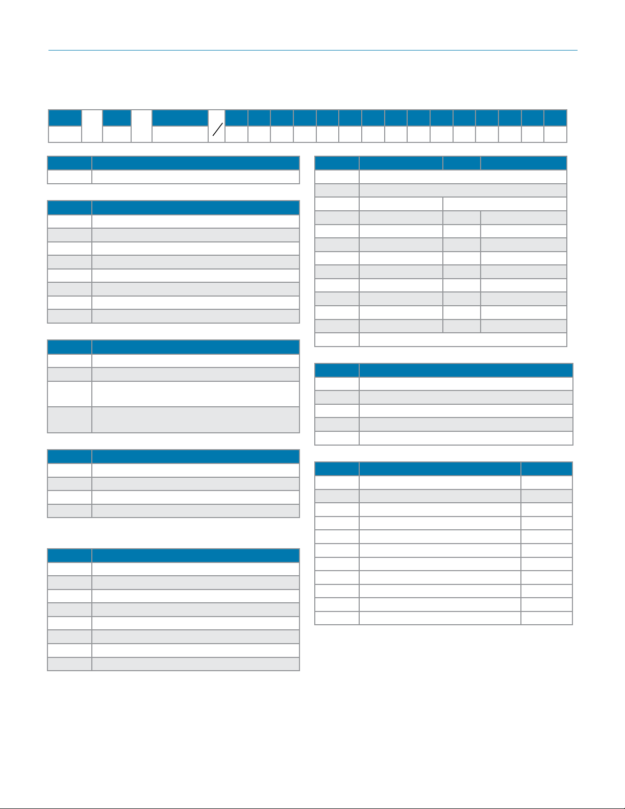
Mark 9020 SerieS Sanitary Ball ValVeS
orDering schematic
Model
9020 3-Pc BPE Sanitary Ball Valve
050 1/2"
075 3/4"
100 1"
150 1-1/2"
200 2"
250 2-1/2"
300 3"
400 4"
6L CF3M 3% Ferrite (Std.)
LF CF3M 1% Ferrite
DL
DF
Size
—
CF3M 3% Ferrite (Std.) w/ 1/2" Tri-clamp
CF3M 1% Ferrite w/ 1/2" Tri-clamp body
Body Mat'l 1 2 3 4 5 6 7 8 9 10 11 12 13 14 15
—
Model Number
Size
Body Material/Drain Option
body condensate drain
condensate drain
3 & 4 Operation
HL Lever (Std.)
NN None
P1 UT-0A-DA STD
P2 UT-0-DA STD S1 UT-0-SR STD
P3 UT-1-DA-STD S2 UT-1-SR STD
P4 UT-2-DA STD S3 UT-2-SR STD
P5 UT-2.5-DA STD S4 UT-2.5-SR STD
P6 UT-3-DA-STD S5 UT-3-SR STD
P7 UT-3.5-DA STD S6 UT-3.5-SR STD
P8 UT-4-DA STD S7 UT-4-SR STD
PF UT-4.5-DA STD SF UT-4.5-SR STD
P9 UT-5-DA STD S8 UT-5-SR STD
ZZ Non-Standard
5 & 6 Actuator Pressure
40 40 psi
60 60 psi
80 80 psi
NN N/A (no pneumatic actuator)
ZZ Non-Standard
1 Seat/Stem Extension
T TFM1600 Enhanced Teon (Std.)
C TFM1600 Cavity Filler Enhanced Teon
E TFM1600 with Enclosed Stem Extension*
S TFM1600 Cavity Filler with Stem Extension*
* Not available on 4" models
2 Ends
A Tri-Clamp / SF1 Int. Fin. (Std.)
B Extended Tube End / SF1 Int. Fin. (Std.)
C** Tri-Clamp x Extended Tube End / SF1 Int. Fin.
D Tri-Clamp / SF4 Int. Fin.
E Extended Tube End / SF4 Int. Fin.
F** Tri-Clamp x Extended Tube End / SF4 Int. Fin.
G** Extended Tube x Tri-Clamp / SF4 Int. Fin.
H** Extended Tube x Tri-Camp / SF1 Int. Fin.
Note: SF1 nish is 20 Ra µin (.5 Ra µm) Mechanical Polish,
SF4 is 15Ra µin (.4 Ra µm) mechanical/electropolish nish
** See page 7
7 & 8 Solenoid Feature Act. Type
3A 3W 8551-120VAC N4 UT-0/5 SR
3C 3W EF8551-120VAC N7 UT-0/5 SR
3J 3W 8317G35-120VAC N4 UT-0/2.5 SR
3M 3W 8321G1-120VAC N4 UT-3/5 SR
3Q 3W EF8317G35-120VAC N7 UT-0/2.5 SR
3R 3W EF8321G1-120VAC N7 UT-3/5 SR
4A 4W 8551-120VAC N4 UT-0A DA
4B 4W 8551-120VAC N4 UT-0/5 DA
4D 4W EF8551-120VAC N7 UT-0A DA
4E 4W EF8551-120VAC N7 UT0/5 DA
ZZ Non-Standard
N4 = NEMA 4 N7 = NEMA 7
-14-
Page 15
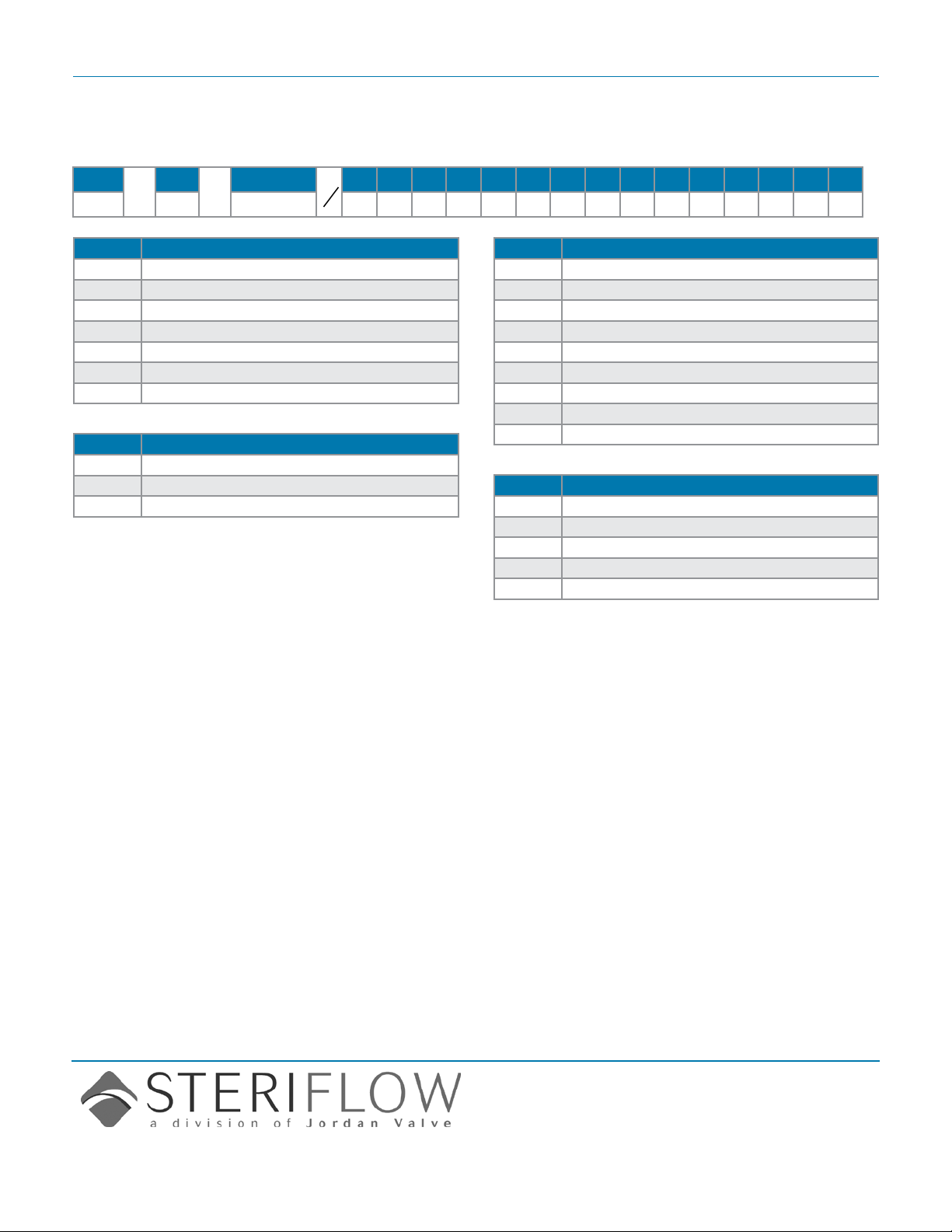
Mark 9020 SerieS Sanitary Ball ValVeS
orDering schematic (con't)
MK9020/0514
Model
—
Size
Body Mat'l 1 2 3 4 5 6 7 8 9 10 11 12 13 14 15
—
9 & 10 Limit Switch
AA LS FMYB-5120-N4 to UT-0/3
AB LS FMYB-5120-N4 to UT-3.5/7
AC LS AMYB-5120-N7 to UT-0/3
AD LS AMYB-5120-N7 to UT-3.5/7
AE LS-AMYB-5120-N4 to Valve
AF LS AMYB-5120-N7 to Valve
0Z Non-Standard
11 & 12 Fail Position
NN Fail Position N/A (No "SR" Actuator)
01 Fail Closed
02 Fail Open
13 & 14 Positioner
AA Siemens 760P (3-15 psi), for UT-0/3
AB Siemens 760P (3-15 psi), for UT-3.5/7
AC Siemens 760E (4-20 mA), for UT-0/3
AD Siemens 760E (4-20 mA), for UT-3.5/7
AE Siemens 2-IQ (4-20 mA) for UT-0/3DA
AF Siemens 2-IQ (4-20 mA) for UT-3.5/7DA
AQ Siemens 2-IQ (4-20 mA), for UT-0/3SR
AR Siemens 2-IQ (4-20 mA), for UT-3.5/7SR
ZZ Non-Standard
15 Misc. Features
1 2-Bug Screen 1/8" SST
2 2-Speed Control 1/8" (4-Way)
3 SST Tube & Fittings F/Automation
4 AFR 4Z030A to UT-0-2.5 SST
Z Non-Standard
Steriflow, a division of Jordan Valve
3170 Wasson Road • Cincinnati, OH 45209
513.533.5600 • 800.543.7311 • 513.871.0105 (f)
sterifl[email protected] • www.steriflowvalve.com
Steriflow Valve reserves the right to make revisions to its product, specifications, literature and related information without notice. Please visit our
website at www.steriflowvalve.com for the latest information on our products.
 Loading...