

Page 1
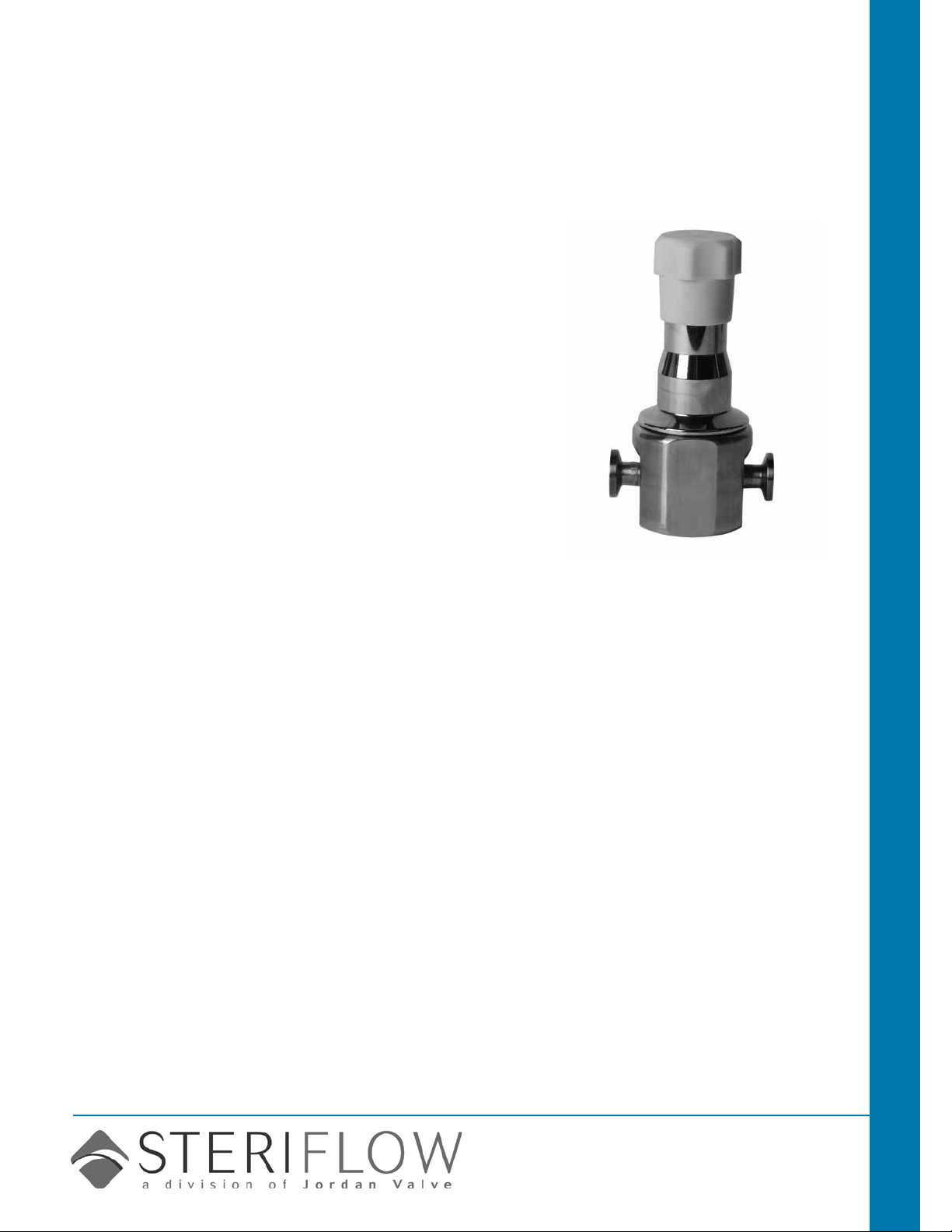
3L/T-2R/S33 Series
CRN Registration Number Available
JSB Series
Back Pressure Regulating Valves for Bio-Pharma
Gas Applications
J-Pure is the rst fully drainable high purity gas back pressure
regulator designed and built specically for hygienic, ASME BPE
gas applications.
Traditionally, regulator manufacturers adapted their industrial
gas regulators for use in biopharm by simply changing the construction materials and surface nish. Not so with the J-Pure
Series Model JSB.
• It's been designed specically to eliminate all threaded connections and contaminant traps below the diaphragm.
• It is completely drainable out the inlet and outlet (an industry rst in compact hygienic regulator design), and compatible with CIP and SIP practices.
• The simple trim design facilitates quick trim change out and
cleaning without valve removal or complete disassembly.
The durable valve body and metal trim components are machined from ASTM A479 316L SST barstock and nished to
ASME BPE SF5 (20Ra micro-inch (0,5 Ra μm), electropolished) standard. The valve is outtted with the rugged Jorlon
diaphragm and Teon or PEEK seats, all FDA approved, USP
Class VI compliant materials. These materials of construction
enable the JSB to withstand the rigors of continuous SIP and
CIP processes if required.
Features
• Fully drainable with no threaded connections, or contaminant traps below the diaphragm
• In-line removable seat and trim signicantly reduce maintenance time
• Barstock construction guarantees material integrity and
surface nish
• High ow rate coupled with high rangeability reduces need
for reduced trim sizes
• Minimized internal volume
• Proprietary Jorlon diaphragm material provides exception-
ally long life and CIP/SIP capability, and FDA and USP
Class VI compliance
• Soft seat material for ANSI Class VI shutoff
Documentation
The following documentation is shipped with each order:
• Steriow Unicert
— Traceable Material Heat Number for body and ferrules
— Certicate of Compliance to FDA and USP Class VI
— Certicate of Surface Finish
• Final Test Reports and Certicate of Origin, O2 cleaning,
etc., available upon request at time of quote, or order
• ASME BPE SF5 (20 Ra μin ,
electropolished) – standard for all
external and wetted metal parts
• Other nishes optional
• O2 cleaning - optional
Typically used in Biopharm or parenteral installations for modulating pressure relief during lling, or other back
pressure applications. Ideal for clean
gases typically found in
bio-pharmaceutical, pharmaceutical
and food & beverage processes including:
• Clean hygienic air
• Nitrogen
• Carbon Dioxide
• Argon
• Oxygen Sparge
• Custom purge or blanket gas
• Post SIP drying
surFace Finish
applications
Sanitary Valves JSB Series Back Pressure Valves
Steriflow by Jordan Valve
3170 Wasson Road • Cincinnati, OH 45209
513.533.5600 • 800.543.7311 • 513.871.0105 (f)
sterifl[email protected] • www.steriflowvalve.com
Page 2
JSB SerieS Bio-Pharma GaS Back PreSSure reGulatinG ValVe
speciFications
Sizes: 1/2" (DN15) & 3/4" (DN20)
Ends: Clamp, Weld-stub or NPT ends
Soft Seat Materials for ANSI Class VI Shut-Off:
• PTFE to +252°F (122°C) continuous or 275°F (135°C)
intermittent [not to exceed 15 min. in a one hour
period] FDA, USP Class VI
• PEEK to +350°F (176,7°C) FDA, USP Class VI
Body Material: 316L SST
Diaphragm Material: PTFE-based Jorlon; FDA, USP
Class VI
Maximum Inlet Pressure: 150 psig (10,5 bar)
Spring Ranges: 8–40 psi (0,06–2,8 bar); 35–60 psi
(2,4–4,1 bar); 50–125 psi (3,4–8,6 bar)
options
Flow Characteristics:
• High Flow: Trim Cv 0.8; Cv for relief valve
sizing is 1.9
• Low Flow: Trim Cv 0.5; Cv for relief valve
sizing is 0.6
Surface Finish: ASME BPE SF5, 20 Ra μin
(0,5 Ra μm) electropolish as standard.
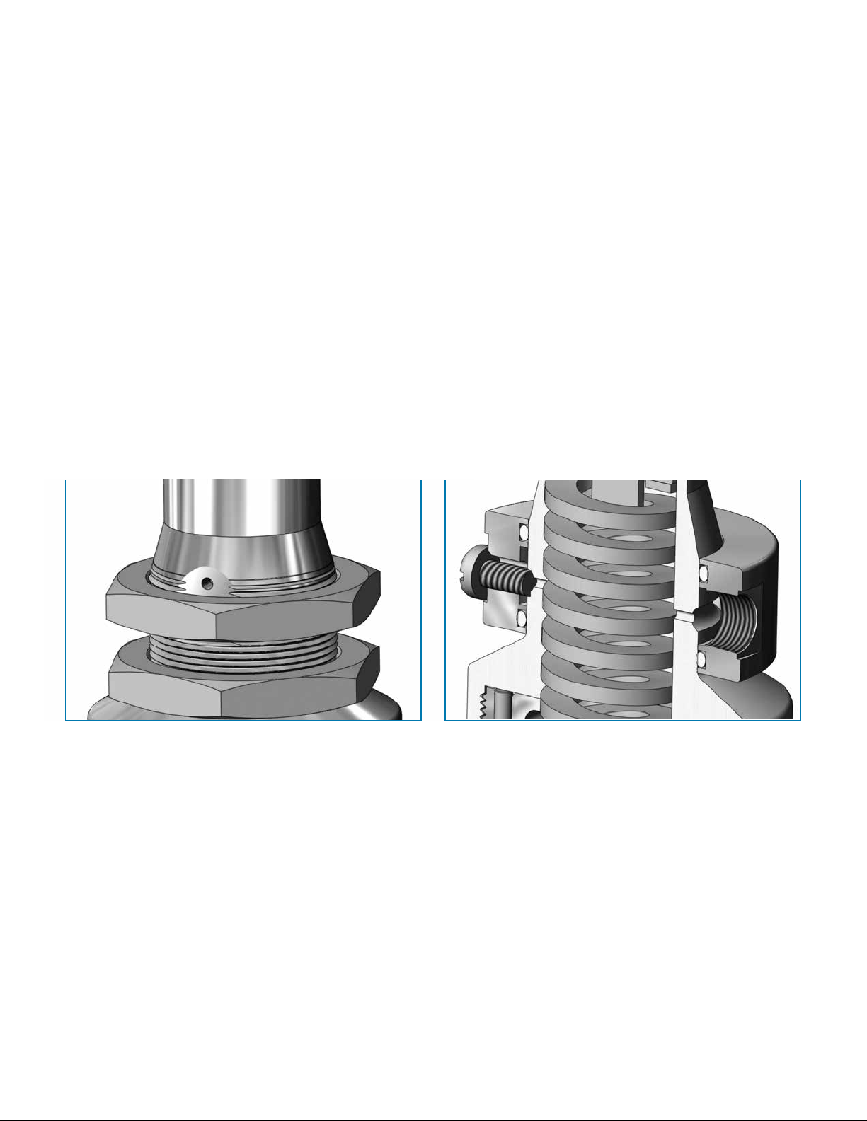
Options:
• Panel Mounting
• Captured Vent
• Inlet-Outlet Gauge
Panel Mount Option Captured Vent Option (1/8" NPT)
option DeFinition
Captured Vent
The captured vent design is for maximum safety for the user when handling toxic or hazardous media. It
features a 1/8" FNPT port located on the spring housing. The user can easily tube this vent to a safe location.
Panel Mount
The panel mount feature requires a panel cut out of 1-1/2" allowing insertion of the threaded spring housing, and a panel mount ring to secure the regulator against the panel.
-2-
Page 3
JSB SerieS Bio-Pharma GaS Back PreSSure reGulatinG ValVe
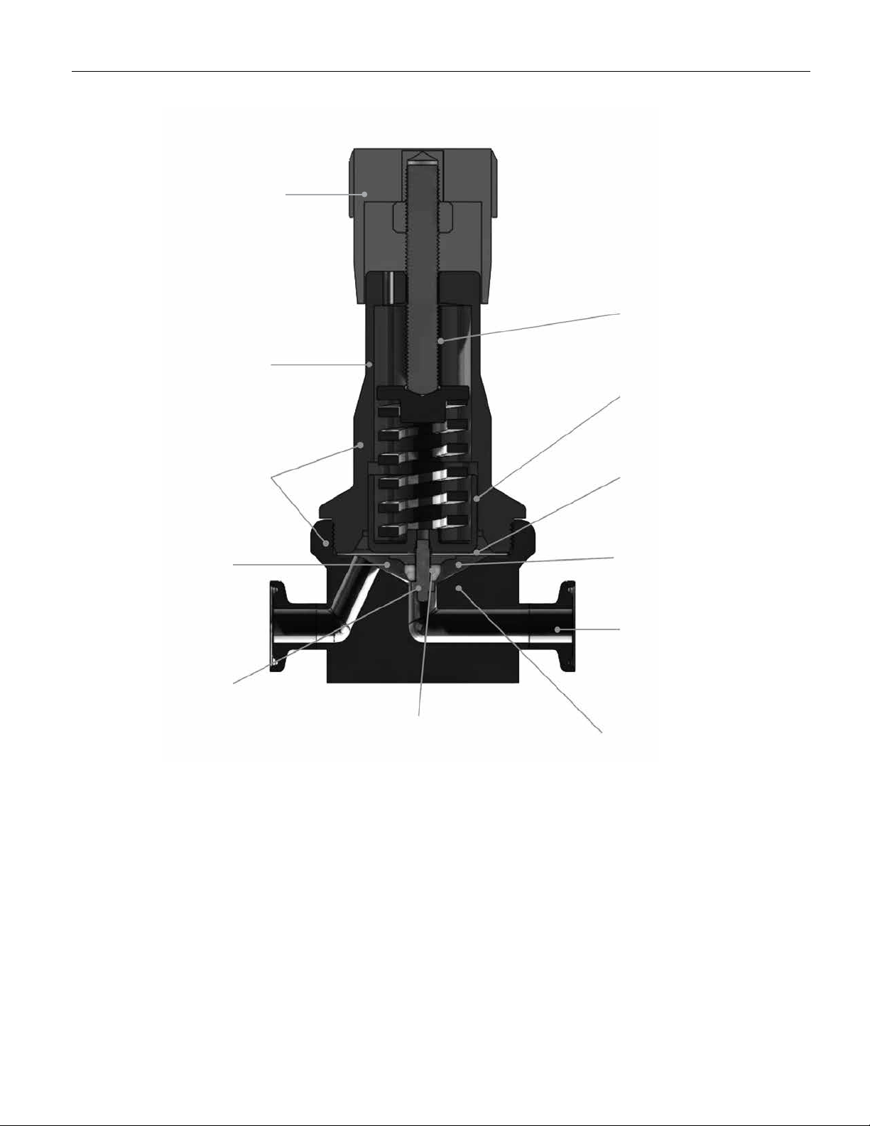
Autoclavable Anodized
Aluminum Knob available
as cataloged option
SST spring chamber
suitable for washdown
Features & BeneFits
Fine thread pitch for
precision setpoint
adjustments
Guiding done above
the wetted process
ASME BPE SF5, 20 Ra μin
(0,5 Ra μm) electropolish standard
No cracks, crevices or
threads below diaphragm
Metal trim
components
100% 316L
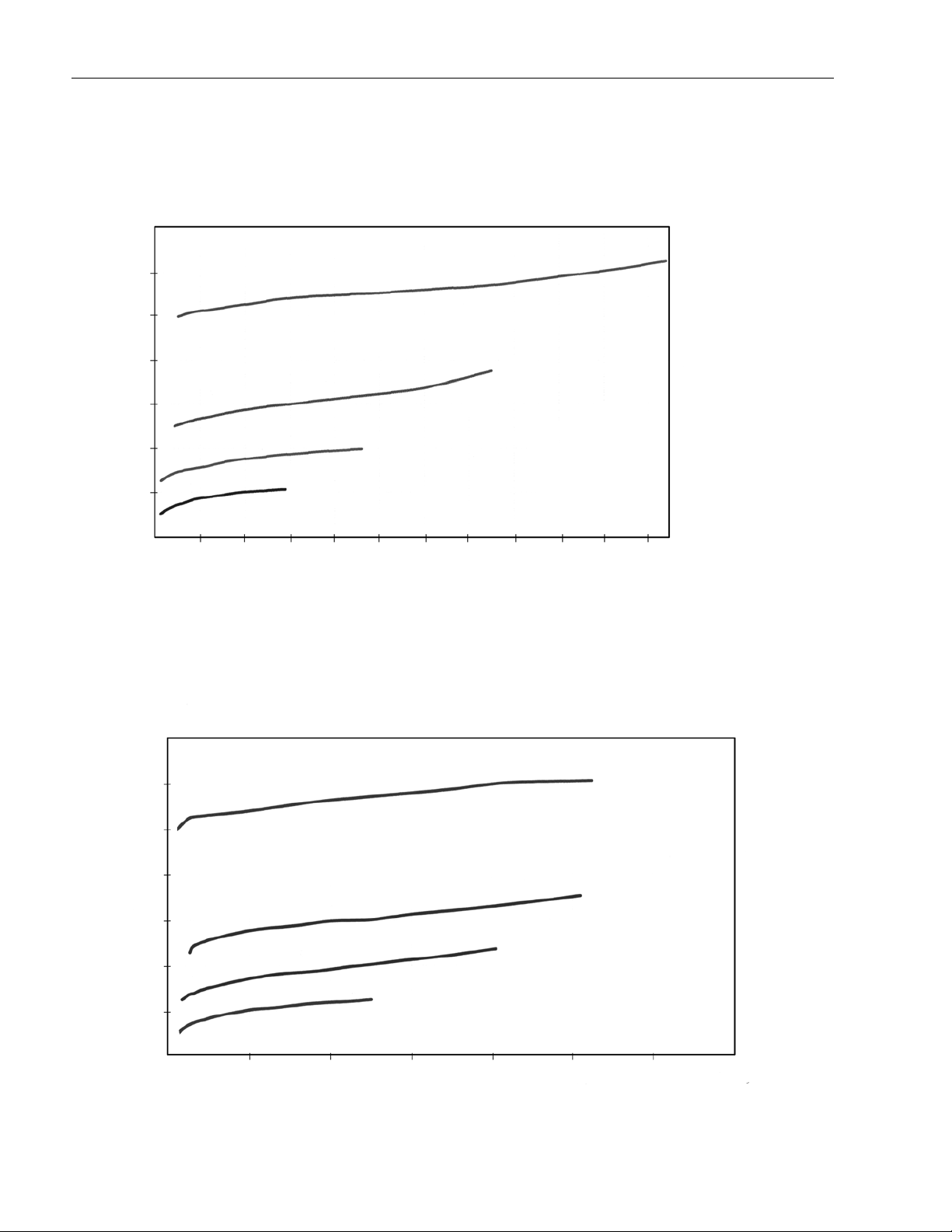
To select a valve with the proper Cv:
1. Convert pressure and ow units to those shown on graph.
2. Select the graph below with a ow range (x axis) that encompasses the minimum and maximum ows
of your installation, and with an appropriate outlet regulated pressure range (y axis). Note: Your max
ow cannot exceed either of the graphs, nor can your desired set point be below 4 psi, or above 125
psi. Note also that the maximum inlet pressure allowed is 150 psig.
3. Plot your desired set point on the graph you chose above, at the ow rate you expect that set point.
4. Pick an outlet pressure spring range ow curve that contains your set point. Eg. 50 - 125 psi, 35-60 psi, etc.
5. Draw a curve with the same slope as #4 above parallel to the spring range ow curve you have
chosen through your plotted set point. That curve approximates the ow of your valve under operating
conditions.
6. Note that you may also use the SFCV sizing program for Globe style valves to calculate approximate
ow or Cv.
FDA/USP Class VI seat and seal
material for ANSI Class VI shutoff
-3-
Jorlon Diaphragm
FDA/USP Class VI
approved – unsurpassed life
Optimized minimal
internal volume
Sanitary clamp
connections
First compact gas regulator
fully drainable in both vertical
and horizontal installation
Page 4
JSB SerieS Bio-Pharma GaS Back PreSSure reGulatinG ValVe
JsB perFormance 0.5 cv
140
120
100
trim Flow Graphs
50-125 psi
80
60
40
Regulated Pressure (psi)
20
0
0 200
400 600 800 1000 1200 1400 1600 1800 2000 2200
JsB perFormance 0.8 cv
140
120
35-60 psi
8-40 psi
8-40 psi
Flow (SCFM)
50-125 psi
100
80
60
40
Regulated Pressure (psi)
20
0
0
400 800 1200 1600 2000 2400 2800
35-60 psi
8-40 psi
8-40 psi
Flow (SCFM)
-4-
Page 5
JSB SerieS Bio-Pharma GaS Back PreSSure reGulatinG ValVe
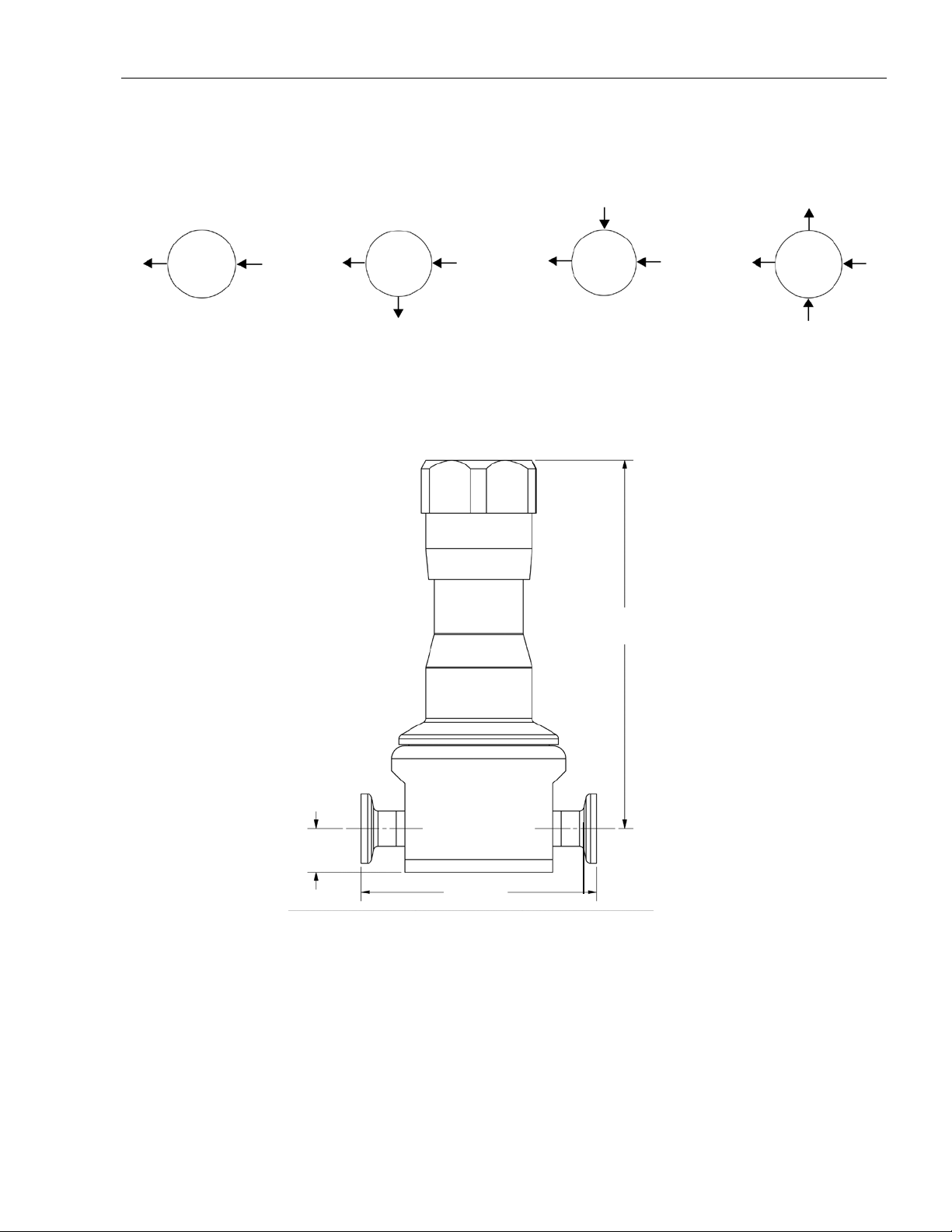
Flow conFiGurations
inlet gage outlet gage
A B D E
outlet inlet outlet inlet outlet inlet outlet inlet
outlet gage inlet gage
* Gage ports are 1/4" FNPT (consult factory for required alternative)
Dimensions, in. (mm)
5.21 (132,2)*
* Add 0.75" (19,1) for
easy removal
0.615 (15,6)
3.31
(84,1)
sample speciFications
Stainless Steel back pressure regulator shall be made from ASTM A479 barstock material, which
includes body and all wetted metal parts, and shall have SF5, 20 Ra μin (0,5 Ra μm) electropolish nish as standard. Regulator shall be fully drainable out the inlet and outlet when installed with
spring housing 90° to ground. Regulator shall be activated by an FDA approved, USP Class VI certied Jorlon diaphragm, stem shall be completely guided above the wet so as not to generate metal
particulate. Regulator shall be free of exposed threads and any cracks or crevices within wetted
process area. Regulator shall have trim that can be replaced inline by simply unthreading the bonnet
and replacing the one piece, diaphragm and trim set. Trim set must be either FDA and USP Class
VI approved Teon, or PEEK.
-5-
Page 6
JSB/0614
JSB SerieS hiGh Purity Bio-Pharma GaS Back PreSSure reGulatinG ValVe
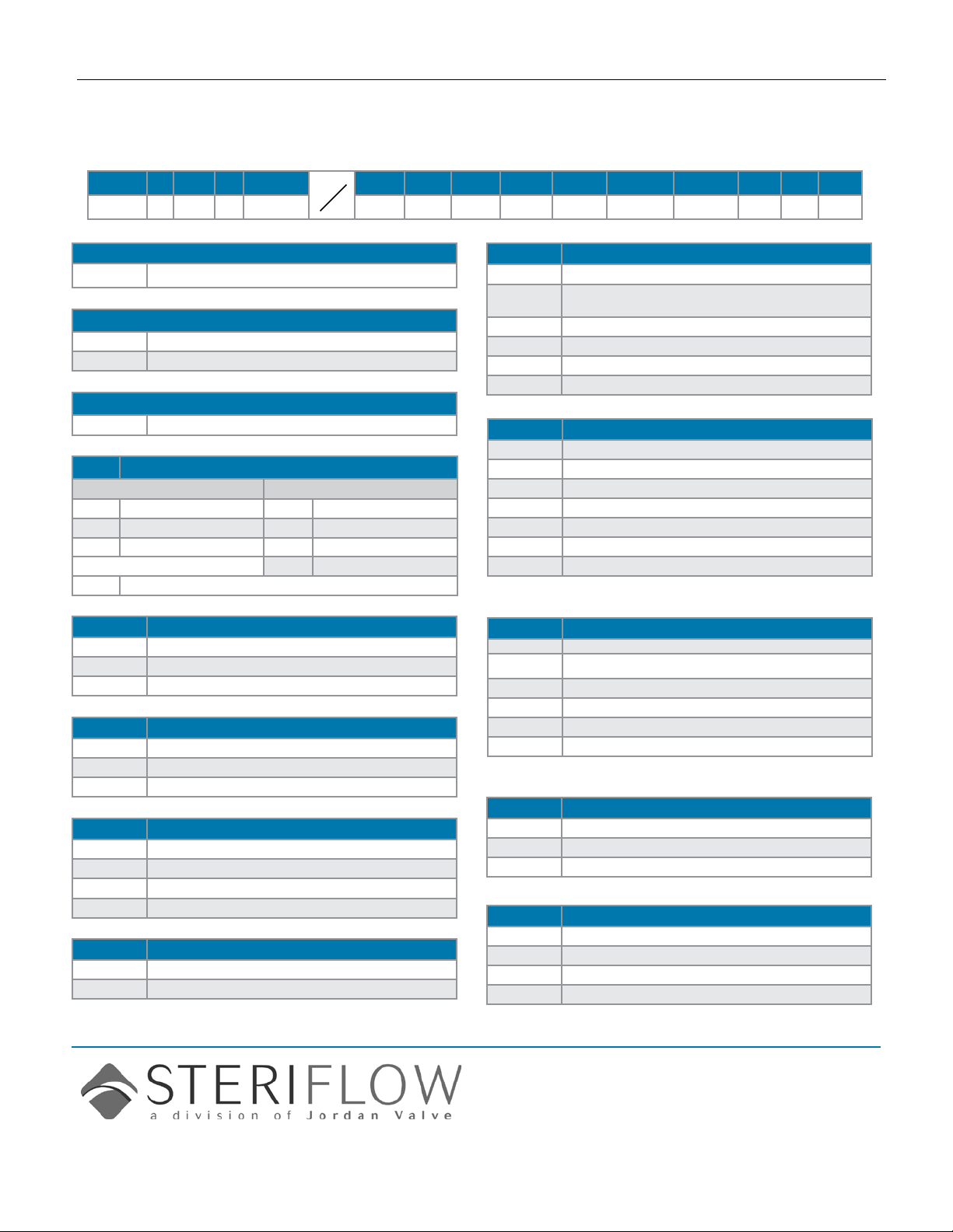
orDerinG schematic
Model Size Material 1 & 2 3 & 4 5 & 6 7 & 8 9 & 10 11 & 12 13 & 14 15 16 17
JSB — 50 — 6L
Model
JSB High Purity Gas Back Pressure Reducing
Size
050 1/2"
075 3/4"
Material
6L Stainless Steel 316L
1 & 2 Body Feature
End Connection Port Conguration
C Tri-Clamp 20 Ra EP A Port "A"
P FNPT 20 Ra EP B Port "B"
T BWE 20 Ra EP D Port "D"
E Port "E"
ZZ Non-Standard
3 & 4 Trim
1S 0.8 Cv
2S 0.5 Cv
ZZ Non-Standard
5 & 6 Seat Material
TF PTFE
PK Peek
ZZ Non-Standard
7 & 8 Range Spring/Outlet Pressure
08 8 - 40 PSI
35 35 - 60 PSI
50 50 - 125 PSI
ZZ Non-Standard
9 & 10 Diaphragm Material
JL Jorlon
ZZ Non-Standard
11 & 12 Actuator
SK Standard Actuator
AK
Standard Actuator / Autoclavable
Anod. Aluminum Knob
PM Panel Mount
CV Captured Vent
TP Tamper Proof
ZZ Non-Standard
13 & 14 Inlet Gauge*
ØB
ØC
ØD
ØE
ØF
ØN
0 - 30 PSIG/Bar (Dual)
0 - 60 PSIG/Bar (Dual)
0 - 100 PSIG/Bar (Dual)
0 - 160 PSIG/Bar (Dual)
0 - 200 PSIG/Bar (Dual)
None
ZZ Non-Standard
* Gauges are Oil Free and O2 clean as standard.
15 Outlet Gauge*
B
C
D
E
N
0 - 30 PSIG/Bar (Dual)
0 - 60 PSIG/Bar (Dual)
0 - 100 PSIG/Bar (Dual)
0-160 PSIG/Bar (Dual)
None
ZZ Non-Standard
* Gauges are Oil Free and O2 clean as standard.
16 SEP Compliance
0
G
Z
None Required
SEP Compliant
Non-Standard
17 Accessories
0
S
X
Z
None Required
Clean For Oil Free*
Clean for Oxygen*
Non-Standard
Steriflow, a division of Jordan Valve
3170 Wasson Road • Cincinnati, OH 45209
513.533.5600 • 800.543.7311 • 513.871.0105 (f)
sterifl[email protected] • www.steriflowvalve.com
Steriflow Valve reserves the right to make revisions to its product, specifications, literature and related information without notice. Please visit our
website at www.steriflowvalve.com for the latest information on our products.
 Loading...