

Page 1
Sensor-Gartenlampe
Bedienungsanleitung
D
Operating Instructions
GB
Mode d’emploi
F
Gebruiksaanwijzing
NL
Istruzioni per l’uso
I
Instrucciones de montaje
E
103577605 08/2011_B Technische Änderungen vorbehalten.
Page 2
Leuchtenfuß mit Rohr
so weit über die Zuleitung zurückziehen, bis
die angezeichneten
Befestigungslöcher
sichtbar werden, dann
die Befestigungslöcher
bohren und den Fuß
mit drei Sechskantschrauben am Boden
befestigen.
10. Den Leuchtenkörper
wieder in das Rohr
stecken und ausrichten,
wie in Punkt 6 beschrieben. Über die abgemantelten Netzleiter ist nun
der beigelegte Schutzschlauch zu ziehen. Die
Leitung samt Schutzschlauch werden jetzt in
der Zugentlastung geklemmt.
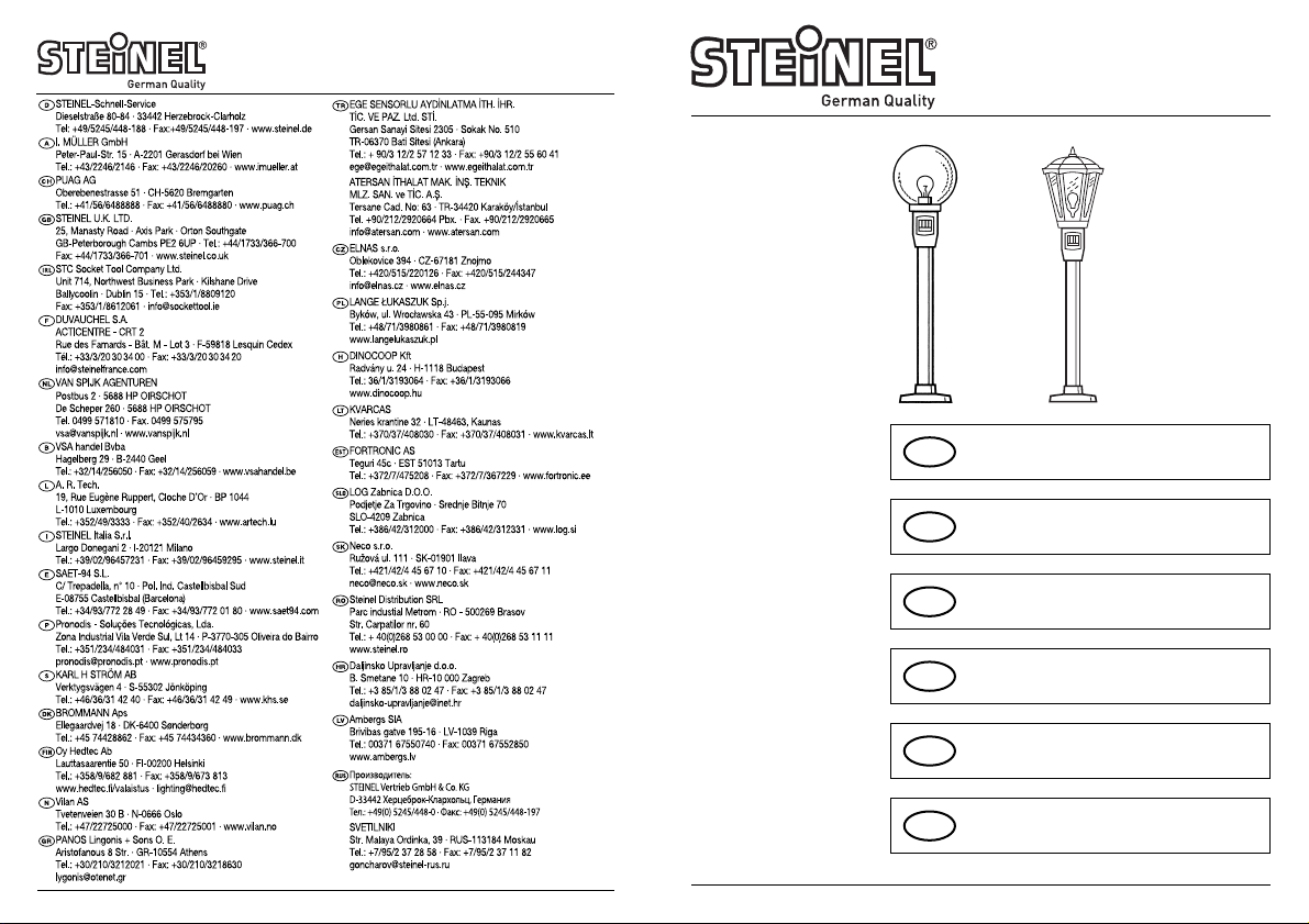
11. Auf eine M3,5 x 10Schraube eine Mutter
drehen. Den Leuchtenkörper leicht anheben und die Schraube
(1) in den Längsschlitz
legen. Sensor in die
gewünschte Position
drehen (Feineinstellung).
Schraube (1) festziehen.
12. Den Schutzschlauch mit
den Leitern durch eines
der vorgesehenen
Löcher in den Anschlussraum zur Lüsterklemme führen.
13. Anschluss der Netz-
zuleitung
Die Netzzuleitung
besteht aus einem
3-poligen Kabel.
L = Stromführender Leiter (schwarz oder braun)
N = Nullleiter (blau)
PE = Schutzleiter
(gelb/grün).
Im Zweifelsfall müssen
Sie die Kabel mit einem
Spannungsprüfer identifizieren; anschließend
wieder spannungsfrei
schalten. Der Erdleiter
(gelb/grün) braucht nicht
angeschlossen zu werden, da die Leuchte
doppelt-schutzisoliert
ist (Schutzklasse II). Den
Erdleiter einfach umbiegen und isolieren. Den
L-Leiter in die Klemme
mit der schwarzen Leitung montieren. Den
N-Leiter in die Klemme
mit der blauen Leitung
montieren.
14. Schiebekappe (Anschlussraumabdeckung)
hochschieben, ausrichten, einrasten und mit
der beiliegenden
Schraube 2,2 x 9,5 festziehen.
15. Glühlampe (max.
100 Watt) einschrauben.
16. Plexiglaskuppel aufsetzen und mit den beiliegenden drei Schrauben
M4 x 12 mm befestigen.
Wichtig: Ein Vertauschen
der Anschlüsse führt im
Gerät oder in Ihrem Sicherungskasten später zum
Kurzschluss. In diesem Fall
müssen nochmals die einzelnen Kabel identifiziert
werden.
3
Durch Kürzen des Standrohres ist es möglich, die
Lampenhöhe individuell zu
bestimmen.
Achtung: Niemals die Aussparung abschneiden
Bei Bedarf können Sie die
Nut der Fußplatte (2) mit
Silikon ausfüllen, um somit
Befestigungsboden und
Fußplatte miteinander zu
verbinden und abzudichten.
Achtung: seitliche Wasserabflussöffnung (3) nicht mit
Silikon ausfüllen.
Bedienungsanleitung
D
Die Einschaltdauer des
Verbrauchers ist stufenlos
einstellbar (von ca. 10 Sek.
bis ca. 15 Min.). Nach Ablauf der eingestellten Zeit
wird bei jeder Bewegung im
Erfassungsbereich die eingestellte Zeit neu aktiviert.
Die sicherste Bewegungserfassung haben Sie, wenn
das Gerät in einem kleinen
Winkel zur Gehrichtung
montiert bzw. ausgerichtet
wirrd und keine Hindernisse
(wie z.B. Bäume, Mauern
etc.) die Sicht behindern.
Der integrierte Dämmerungsschalter (LDR) ist
ebenfalls stufenlos einstellbar (von ca. 2 Lux bis ca.
2000 Lux).
2 Lux = Nachtbetrieb,
2000 Lux = Tagbetrieb.
Das Prinzip
2
Der eingebaute pyroelektrische Infrarot-Detektor
erfasst die unsichtbare
Wärmestrahlung von sich
bewegenden Körpern
(Menschen, Tieren, etc.).
Diese so erfasste Wärmestrahlung wird elektronisch
umgesetzt und schaltet die
Lampe. Durch Hindernisse,
wie z.B. Mauern oder
Glasscheiben, wird keine
Wärmestrahlung erkannt,
es erfolgt also auch keine
Schaltung.
Installation
Achtung: Die Montage
bedeutet Netzanschluss.
230 Volt bedeutet Lebensgefahr. Bei der Installation
der Garten-Sensorlampe
handelt es sich um eine
Arbeit an der Netzspannung; sie muss daher fachgerecht nach VDE 0100
ausgeführt werden. Daher
vor Beginn der Arbeiten den
Strom abschalten und
Spannungsfreiheit mit
einem Spannungsprüfer
überprüfen.
01. Das Rohr so in den
Leuchtenfuß stecken,
dass die kleine Aussparung nach oben zeigt.
Dann mit 4 Schrauben
(3 x 16) von unten festschrauben.
02. Die Zuleitung von unten
durch das Rohr schieben. Wichtig: Die Zuleitung muss mindestens
13 cm länger sein als
das Rohr. Die Zuleitung
muss doppelt-schutzisoliert bis in das Leuchtenoberteil hineingeführt
werden.
03. Schiebekappe (Anschlussraumabdeckung)
von dem Leuchtenkörper abziehen und über
das Rohr nach unten
schieben.
04. Äußere Zuleitung ca.
10 cm abisolieren.
05. Den Leuchtenkörper in
das Rohr stecken, dabei
die Zuleitung durch die
vorgesehene Öffnung
führen.
06. Den Leuchtenkörper so
drehen, dass sich die
Lüsterklemme über dem
Langschlitz im Rohr befindet.
07. Die so vorgefertigte
komplette Lampe mit
Sensor so drehen, dass
der Sensor ungefähr in
die gewünschte Richtung zeigt (Grobeinstellung).
08. Die Befestigungslöcher
vom Fuß auf den Boden
übertragen bzw. anzeichnen.
09. Den Leuchtenkörper
wieder aus dem Rohr
entfernen und den
2–12 m
von 100 cm – 50 cm
(2)
(3)
Page 3
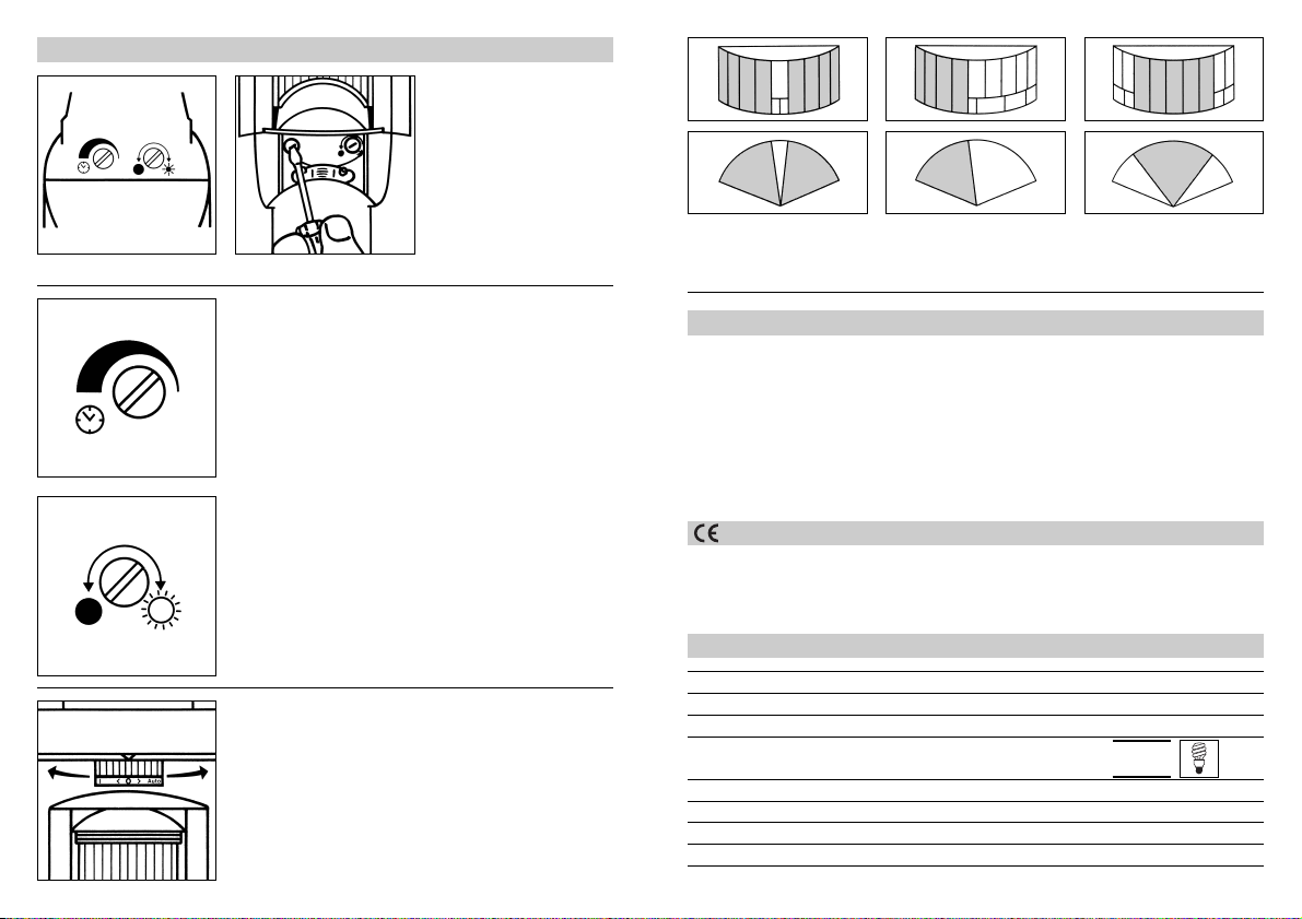
5
Je nach Bedarf kann der
Erfassungsbereich optimal
eingestellt werden. Mit den
beigelegten Abdeckungen
können Sie den Erfassungsbereich des Sensors zusätzlich bestimmen. Linsensegmente können abge-
deckt werden, um somit
Fehlschaltungen durch z.B.
Autos, Passanten auszuschließen.
Soll der Verbraucher unabhängig von einer Wärmequelle im Erfassungsbereich
eingeschaltet werden, wird
der hausinterne Netzschalter einmal kurz betätigt. So
wird der Verbraucher für die
eingestellte Zeit aktiv.
Witterungseinflüsse sowie
starke elektromagnetische
Felder können die Funktion
der Gartenlampe beeinträchtigen. Bei starken
Windböen, Schnee, Regen,
Hagel kann es zu einer
Fehlschaltung kommen, da
die plötzlichen Temperaturschwankungen nicht von
Wärmequellen unterschieden werden können.
Die Fresnellinse (Erfassungslinse) kann bei Verschmutzung mit einem
feuchten Tuch (ohne Reinigungsmittel) gesäubert
werden.
Betrieb
Dieses Produkt erfüllt die
- Niederspannungrichtlinie 2006/95/EG
- EMV-Richtlinie 2004/108/EG
Konformitätserklärung
Montage: Netzanschluss 220–240 V
Erfassungswinkel des Sensors: 180° horizontal, 8° vertikal
Schwenkbereich des Sensors: 55° horizontal, 35° vertikal
Schaltzeit, einstellbar: 10 Sek. – 15 Min.
Reichweite: 12 m frontal, 10 m seitlich
Erfassungsfläche: ca. 240 m
2
Leistung der Glühlampe: max. 100 Watt
Schutzart: IP 44
Technische Daten
Funktion
4
Nachdem die SensorLampe
angeschlossen ist, kann
diese eingeschaltet werden.
Zwei Einstellmöglichkeiten
stehen nun auf der Unterseite des Gerätes zur Verfügung.
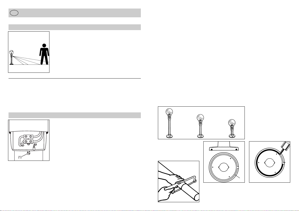
Achtung! Schiebekappe
nach unten ziehen und Sensorkopf nach oben schwenken. Mit einem kleinen
Schraubendreher von unten
Zeit- und Dämmerungseinstellung vornehmen.
A) Ausschaltverzögerung
(Zeiteinstellung)
Die gewünschte Leuchtdauer des Betriebsmittels
kann auf der Unterseite des
Gerätes stufenlos von ca.
10 Sek. bis max. 15 Min.
eingestellt werden. Stellschraube Rechtsanschlag
bedeutet kürzeste Zeit, ca.
10 Sek. Stellschraube
Linksanschlag bedeutet
längste Zeit, ca. 15 Min.
(Bei Auslieferung ist das
Gerät werkseitig auf kürzeste Zeit eingestellt). Bei der
Einstellung des Gerätes für
den Erfassungsbereich und
für den Funktionstest wird
empfohlen, die kürzeste Zeit
einzustellen.
B) Dämmerungseinstellung (Ansprechschwelle)
Die gewünschte Ansprechschwelle des Gerätes kann
ebenfalls auf der Unterseite
stufenlos von ca. 2 Lux bis
2000 Lux eingestellt werden.
Stellschraube Rechtsanschlag bedeutet Tageslichtbetrieb ca. 2000 Lux. Stellschraube Linksanschlag bedeutet Dämmerungsbetrieb
ca. 2 Lux. (Bei Auslieferung
ist das Gerät werkseitig auf
Tageslichtbetrieb eingestellt.)
Bei der Einstellung des
Gerätes für den Erfassungsbereich und für den Funktionstest bei Tageslicht
muss die Stellschraube auf
Rechtsanschlag stehen.
Drei Schalter-Funktionen
stehen zur Auswahl und
können am Gerät über dem
Sensor eingestellt werden.
Schalter nach links schieben. Schalterstellung (I):
Lampe leuchtet im Dauerbetrieb.
Schalterstellung (0)
Lampe ist ausgeschaltet.
Schalter nach rechts schieben. Schalterstellung (Auto):
Lampe schaltet im Sensorbetrieb.
Tipp!
min.
5 Min.
Page 4

7
Dieses Steinel-Produkt ist
mit größter Sorgfalt hergestellt, funktions- und sicherheitsgeprüft nach geltenden
Vorschriften und anschließend einer Stichprobenkontrolle unterzogen.
Steinel übernimmt die
Garantie für einwandfreie
Beschaffenheit und Funktion.
Die Garantiefrist beträgt
36 Monate und beginnt
mit dem Tag des Verkaufs
an den Verbraucher. Wir
beseitigen Mängel, die auf
Material- oder Fabrikationsfehlern beruhen, die Garantieleistung erfolgt durch
Instandsetzung oder
Austausch mangelhafter
Teile nach unserer Wahl.
Eine Garantieleistung entfällt für Schäden an Verschleißteilen sowie für
Schäden und Mängel,
die durch unsachgemäße
Behandlung, Wartung oder
durch Verwenden von
Fremdteilen auftreten.
Weitergehende Folgeschäden an fremden Gegenständen sind ausgeschlossen.
Die Garantie wird nur gewährt, wenn das unzerlegte
Gerät mit kurzer Fehlerbeschreibung, Kassenbon
oder Rechnung (Kaufdatum
und Händlerstempel), gut
verpackt, an die zutreffende
Servicestation eingesandt
wird.
Reparaturservice:
Nach Ablauf der Garantie-
zeit oder Mängeln ohne
Garantieanspruch repariert
unser Werkservice. Bitte
das Produkt gut verpackt
an die nächste Servicestation senden.
Funktionsgarantie
6
Störung Ursache Abhilfe
Sensor-Gartenlampe
ohne Spannung
Haussicherung defekt,
nicht eingeschaltet,
Leitung unterbrochen
Kurzschluss
neue Haussicherung,
Netzschalter einschalten,
Leitung überprüfen mit
Spannungsprüfer
Anschlüsse überprüfen
Sensor-Gartenlampe
schaltet nicht ein
bei Tagesbetrieb
Dämmerungseinstellung
steht auf Nachtbetrieb
Leuchtmittel defekt
Netzschalter AUS
Haussicherung defekt
Erfassungsbereich nicht
gezielt
neu einstellen
Glühlampe austauschen
einschalten
neue Haussicherung,
evtl. Anschluss prüfen
neu justieren
Sensor-Gartenlampe
schaltet nicht aus
dauernde Bewegung im
Erfassungsbereich
Bereich kontrollieren und
evtl. neu justieren, bzw.
abdecken
Sensor-Gartenlampe
schaltet immer EIN/AUS
Tiere bewegen sich im
Erfassungsbereich
Sensor höher schwenken
bzw. gezielt abdecken,
Bereich umstellen bzw.
abdecken
Sensor-Gartenlampe
schaltet unerwünscht ein
Wind bewegt Bäume und
Sträucher im Erfassungsbereich
Erfassung von Autos auf
der Straße
plötzliche Temperatur-
veränderungen durch
Witterung (Wind, Regen,
Schnee) oder Abluft aus
Ventilatoren, offenen
Fenstern
Bereich umstellen, bzw.
abdecken
Bereich umstellen,
Sensor abschwenken
Bereich verändern,
Montageort verlegen
Sensor-Gartenlampe
Reichweiteveränderung
andere Umgebungstem-
peraturen
bei Kälte Sensorreichwei-
te durch Abschwenken
verkürzen
bei Wärme höher stellen
Betriebsstörungen
Page 5

holes. Now drill mounting holes and secure
base to mounting surface using three hexagon head cap screws.
10. Insert the light enclosure
back into the tube and
align as described in
point 6. Now fit the protective sleeve provided
over the stripped mains
conductor. The conductor, including protective
sleeve, must now be
clamped in the cable
grip.
11. Fit a nut onto an M3.5 x
10 screw. Slightly raise
top section of lamp and
insert screw (1) into slot.
Turn sensor to chosen
position (fine adjustment). Tighten screw
12. Thread the protective
sleeve with the conductors through one of the
holes provided in the
terminal compartment
and take it to the terminal block.
13. Connecting mains
power supply lead
The mains power supply
lead is a 3-core cable.
L = phase conductor
(black or brown)
N = neutral conductor
(blue)
PE = protective earth
conductor (green/yellow)
If you are in any doubt,
you must identify the
cables using a voltage
tester; then disconnect
power supply again. The
earth conductor (yellow/green) does not
need to be connected
because lamp is doubly
insulated (Class II).
Simply bend the earth
conductor back and insulate. Fit L conductor
into terminal with black
lead. Fit the N conductor
into terminal with blue
lead.
14. Push up slide cap (terminal compartment),
align, clip into place and
secure in place using
2.2 x 9.5 screw provided.
15. Screw in light bulb
(100 watts max.).
16. Mount polycarbonate
globe and secure in
place with the three M4
x 12 screws provided.
Important: Getting the cable connections crossed will
later on produce a short
circuit in the unit or in your
fuse box. In this case, you
must once again identify
the individual wires and
connect them correctly.
9
The tubular stem tube
may be shortened to adjust
the lamp height to suit your
requirements.
Attention: never cut off the
notch.
If you wish, you can fill the
groove in the base plate (2)
with silicone to attach and
seal the base plate to the
mounting surface.
Attention: Be careful not to
fill silicone into the water
drainage opening (3) at the
side.
Operating Instructions
GB
The on time can be continuously adjusted (from approx. 10 sec. to approx.
15 min.). After the selected
time elapses, any movement in the detection zone
will re-activate the timer.
The most reliable way of
detecting motion is to install
the light in such a way that
the sensor is aimed more
or less across the direction
in which a person would
walk and by ensuring that
no obstacles (such as trees,
walls etc.) obstruct the line
of sensor vision.
The integrated photoelectric
lighting controller (LDR) is
also continuously adjustable (from approx. 2 lux to
approx. 2000 lux).
2 lux = night-time operation
2000 lux = daytime operation
Operating Principle
8
The built-in pyro-electric
infrared detector senses the
invisible heat radiated by
moving objects (people,
animals, etc.). Detected in
this way, the heat is converted electronically into a signal that switches the light
on. Heat is not detected
through obstacles, such as
walls or panes of glass.
Heat radiation of this type
will, therefore, not activate
the light.
Installation
Attention: Installation invol-
ves connecting the unit to
the mains power supply.
Mains voltage of 230 V can
be lethal. To install the Garden SensorLamp, you must
work with mains voltage;
this work must therefore be
carried out professionally in
accordance with the applicable wiring regulations and
electrical operating condi-
tions. Therefore disconnect
the power supply prior to
commencing work and check
that the circuit is dead using
a voltage detector.
01. Insert tubular stem into
lamp base so that the
small notch faces upwards. Afterwards,
fasten from below using
4 screws (3 x 16).
02. Route power supply
lead from below through
tubular stem. Impor-
tant: Power supply lead
must be at least 13 cm
longer than tubular
stem. Power supply
lead must be doubly insulated into top section
of lamp.
03. Pull slide cap (terminal
compartment cover)
from lamp and slide
down over tubular stem.
04. Strip about 10 cm of
insulation off end of
power supply lead.
05. Insert top section of
lamp into tubular stem,
routing power supply
lead through opening
provided.
06. Turn top section so that
terminal block is positioned above the slot in
the tubular stem.
07. Pre-assembled in this
way, turn lamp and sensor so that sensor
points more or less in
chosen direction (rough
adjustment).
08. Transfer position of ba-
se mounting holes onto
mounting surface.
09. Remove top section of
lamp from tubular stem
again. Ease back lamp
base and tubular stem
over power supply lead
so as to reveal mounting
2–12 m
from 100 cm to 50 cm
(2)
(3)
Page 6

11
The detection zone can be
optimised to suit requirements. Using the shrouds
provided with the lamp, you
can also adjust the sensor's
detection zone. Lens segments can be covered so as
to prevent the light from
being triggered inadvertently, for example, by cars or
passers-by.
If you want the light to come on independently of a
heat source, switch on the
indoor power switch momentarily. This will activate
the light for the period
selected.
Weather as well as strong
electromagnetic fields can
affect operation of the Garden Lamp. Strong gusts of
wind, snow, rain or hail may
cause switching errors because the unit cannot
distinguish sudden change
in temperature from heat
sources.
The Fresnel lens (detection
lens) can be wiped clean
with a damp cloth (not
using detergent) if it gets
dirty.
Operation
This product complies with
- Low Voltage Directive 2006/95/EC
- EMC Directive 2004/108/EC
Declaration of conformity
Technical Specifications
Functions
10
Once the SensorLamp has
been connected, it can be
switched on. Two setting
controls are provided on the
bottom of the unit.
Attention: Pull down slide
cap and tilt up sensor head.
Use a small screwdriver
from below to set timer and
light threshold.
A) Switch-off delay (time
setting)
At the bottom of the unit
you can set the light to
come on for any period between approx. 10 sec. and
a maximum of 15 min. The
shortest period, approx. 10
sec., is selected by turning
the control fully clockwise.
The longest period, 15 min.,
is selected by turning the
control fully anticlockwise.
(The unit leaves the factory
set to the shortest time). It
is recommended to select
the shortest time for adjusting the detection zone
and for performing the walk
test.
B) Light level setting
(threshold)
The desired light threshold
can also be adjusted continuously from about 2 lux to
2,000 lux on the bottom of
the unit. Turn control fully
clockwise to select daylight
operation at about 2,000
lux. Turned fully anticlockwise, control is set to duskto-dawn operation at about
2 lux (on leaving factory,
light is set to daytime
operation).
The control must be turned
fully clockwise when adjusting the detection zone
and performing the walk
test in daylight.
Three switch setting capabilities are provided on the
unit above the sensor.
Slide switch to left; switch
position (I): Lamp is switched on all the time.
Switch position (0)
Lamp is switched off.
Slide switch to right; switch
position (Auto): Lamp controlled in sensor mode.
Mains power supply: 220–240 V mains connection
Sensor angle of coverage: 180° horizontal, 8° vertical
Sensor swivel range: 55° horizontal, 35° vertical
"ON" time, adjustable: 10 sec. – 15 min.
Reach: 12 m in front, 10 m at sides
Detection area: approx. 240 m
2
Light bulb output: 100 watt max.
Enclosure: IP 44
Tip!
at
least
5 min.
Page 7

13
This STEINEL product has
been manufactured with
great care, tested for proper
operation and safety in accordance with applicable
regulations and then subjected to random sample
inspection. STEINEL guarantees that it is in perfect
condition and proper working order. The warranty
period is 36 months, starting from the date of sale
to the consumer.
We will remedy defects caused by material flaws or
manufacturing faults. The
warranty will be met by
repair or replacement of
defective parts at our own
discretion. The warranty
does not cover damage
to wear parts, nor does it
cover damage or defects
caused by improper treatment, maintenance or the
use of non-genuine parts.
Further consequential damage to other objects shall
be excluded.
Claims under the warranty
will only be accepted if the
product is sent fully assembled and well packed complete with a brief description of the fault as well as a
receipt or invoice (date of
purchase and dealer's
stamp) to the appropriate
Service Centre.
Repair Service:
Our Customer Service
Department will repair faults
not covered by warranty or
after the warranty period.
Please send the product
well packed to your nearest
Service Centre.
Functional Guarantee
12
Malfunction Cause Remedy
Garden SensorLamp without power
House fuse faulty, not
switched on, break in
wiring
Short-circuit
Renew house fuse,
switch on mains power
switch, check wiring with
voltage tester
Check connections
Garden SensorLamp will
not switch on
Twilight control set to
night-time mode during
daytime operation
Bulb faulty
Power switch OFF
House fuse faulty
Detection zone not pro-
perly targeted
Adjust setting
Change bulb
Switch on
Renew house fuse, check
connection if necessary
Re-adjust
Garden SensorLamp will
not switch off
Continuous movement in
the detection zone
Check detection zone
and re-adjust if necessary, or attach shrouds
Garden SensorLamp keeps
switching ON/OFF
Animals moving in detec-
tion zone
Tilt sensor up or use
shrouds to target more
precisely
Garden SensorLamp switches on when it should not
Wind moving trees or
bushes in detection zone
Cars in street being
detected
Sudden temperature
changes due to weather
(wind, rain, snow) or air
expelled from ventilators,
open windows
Change detection zone or
attach shrouds
Change detection zone,
tilt sensor down
Adjust detection zone,
change site of installation
Reach of Garden SensorLamp changes
Differing ambient tem-
peratures
In cold weather, shorten
sensor reach by tilting
down
Tilt up in warm weather
Troubleshooting
Page 8

trous marqués au sol
soient visibles. Percer
les trous de fixation et
fixer le pied au sol avec
des vis six pans.
10. Replacer le bloc d'éclairage dans le tube et l'aligner, comme décrit au
point 6. Enfiler ensuite
sur les conducteurs
dénudés la gaine protectrice fournie. Puis
bloquer la ligne et sa
gaine protectrice dans
la décharge de traction.
11. Visser un écrou sur une
vis M3,5 x 10. Soulever
légèrement le bloc
d’éclairage et poser la
vis (1) dans la fente
oblongue. Régler le détecteur dans la position
souhaitée en le faisant
pivoter (réglage de précision). Serrer la vis (1).
12. Amener la gaine protectrice et les conducteurs
au domino de raccorde-
ment en passant par
un des perçages prévus
dans l'espace de
raccordement.
13. Branchement du câble
secteur
Le câble secteur est
composé d’un câble à
3 conducteurs :
L = phase
(noir ou marron)
N = neutre (bleu)
PE = terre (vert/jaune)
En cas de doute, il faut
identifier les câbles
avec un testeur de tension puis les remettre
hors tension. Il n’est
pas nécessaire de raccorder le conducteur de
terre (jaune/vert) car la
lampe a une isolation
double (classe II). Il suffit de replier le conducteur de terre et de l’isoler. Raccorder le conducteur de phase à la
borne du conducteur
noir. Raccorder le conducteur de neutre à la
borne du conducteur
bleu.
14. Remonter la plaque
coulissante (cache-bornes), l’ajuster, l’enclencher et la fixer avec la
vis 2,2 x 9,5 fournie.
15. Visser une ampoule à
incandescence (max.
100 watts).
16. Poser le globe en plexiglas et le fixer avec les
deux vis M4 x 12 mm
fournies.
Attention: une inversion
des branchements entraînera plus tard un court-circuit
dans l’appareil ou dans le
boîtier à fusibles. Dans ce
cas, il faut à nouveau identifier les câbles.
15
On peut modifier la hauteur du luminaire en coupant le tube.
Attention: ne jamais
découper l’évidement.
Si nécessaire, vous pouvez
remplir de silicone la rainure
de la plaque d’assise (2)
afin de fixer ensemble le
fond de fixation et la plaque
d’assise et de les étanchéifier.
Attention: ne pas remplir
de silicone le trou latéral
d’évacuation de l’eau (3).
Mode d’emploi
F
La durée de commutation
de l’appareil raccordé est
réglable en continu (d’environ 10 s à 15 min). Après
écoulement de la durée
réglée, chaque mouvement
réactive la temporisation
réglée. La détection des
mouvements est la plus
fiable quand l’appareil est
placé perpendiculairement
au sens de passage et
qu’aucun obstacle (arbre,
mur, etc.) n’obstrue le
champ de visée.
L’interrupteur crépusculaire
(LDR) intégré est également
réglable en continu (d’environ 2 lux à 2000 lux).
2 lux = mode nocturne,
2000 lux = mode diurne.
Le principe
14
Le détecteur infrarouge pyroélectrique intégré détecte
le rayonnement de chaleur
invisible émis par les corps
en mouvement (personnes,
animaux, etc.). Ce rayonnement de chaleur capté est
ensuite traité par un systè-
me électronique qui met en
marche la lampe. Les
obstacles comme les murs
ou les vitres s’opposent à la
détection du rayonnement
de chaleur et empêchent
toute commutation.
Installation
Attention: le montage com-
prend le raccordement au
secteur. La tension de 230 V
peut être mortelle. L’installation du luminaire de jardin
à détecteur implique une
intervention sur le réseau
électrique et doit donc être
effectuée correctement et
conformément à la norme
NF C-15100. Avant de commencer le travail, il faut
donc couper le courant et
s’assurer de l’absence de
courant à l’aide d’un testeur
de tension.
01. Enfoncer le tube dans le
pied du luminaire afin
que le petit évidement
soit orienté vers le haut.
Le fixer ensuite par dessous avec 4 vis (3 x 16).
02. Passer le câble dans le
tube en l’introduisant
par le bas. Attention: le
câble doit être plus long
que le tube d’au moins
13 cm. Le câble doit
avoir une isolation
double jusque sur la
section introduite dans
la partie supérieure du
luminaire.
03. Retirer la plaque coulis-
sante (cache-bornes) du
bloc d’éclairage et la
faire glisser vers le bas
sur le tube.
04. Retirer la gaine du câble
sur une longueur d’environ 10 cm.
05. Enfoncer le bloc d’éclai-
rage dans le tube en faisant passer le câble
dans l’ouverture prévue.
06. Faire pivoter le bloc
d’éclairage afin que le
domino se trouve audessus de la fente
oblongue du tube.
07. Faire pivoter le luminaire
ainsi préassemblé afin
que le détecteur soit à
peu près orienté dans la
direction souhaitée
(réglage approximatif).
08. Marquer au sol l’empla-
cement des trous pour
la fixation du pied.
09. Retirer le bloc d’éclaira-
ge du tube et faire remonter le tube sur le
câble jusqu’à ce que les
emplacements des
2–12 m
100 cm – 50 cm
(2)
(3)
Page 9

17
Vous pouvez optimiser la
portée en fonction de vos
besoins. Vous pouvez
également régler la zone de
détection à l’aide des caches fournis et masquer
des segments de lentille
afin d’éviter des déclenche-
ments intempestifs causés
p. ex. par des voitures, des
passants, etc.
Si l’appareil raccordé doit
être mis sous tension indépendamment de la présence d’une source de chaleur
dans la zone de détection, il
faut actionner une fois rapidement l’interrupteur monté
sur le réseau domestique.
Ceci active l’appareil raccordé pour la durée réglée.
Les intempéries et les
champs électroma-
gnétiques intenses peuvent
nuire au bon fonctionnement du luminaire de jardin
à détecteur.
Les rafales de vent violentes, la neige, la pluie, la
grêle peuvent entraîner un
déclenchement intempestif
car le détecteur ne peut pas
distinguer les brusques variations de température des
sources de chaleur.
Si la lentille de Fresnel (lentille de détection) se salit,
vous pouvez la nettoyer
avec un chiffon humide (ne
pas utiliser de détergent).
Fonctionnement
Ce produit est conforme à
- la directive basse tension 2006/95/CE
- la directive compatibilité électromagnétique 2004/108/CE
Déclaration de conformité
Caractéristiques techniques
16
Après avoir branché le luminaire à détecteur, vous pouvez le mettre en service.
Deux possibilités de réglage
sont disponibles sur la face
inférieure de l’appareil.
Attention ! Tirez vers le bas
la plaque coulissante et faites pivoter la tête du détecteur vers le haut. Vous pouvez maintenant accéder par
le bas avec un petit tournevis aux réglages de temporisation de l’extinction et de
crépuscularité.
A) Temporisation de l’extinction (minuterie)
La durée d’éclairage souhaitée est réglable en continu d’environ 10 s à 15 min
maxi à l’aide de la vis située
sous l’appareil. La temporisation est à son minimum
(env. 10 s) quand la vis de
réglage est en butée à droite, à son maximum (env.
15 min) quand la vis est en
butée à gauche.
(L’appareil est livré réglé sur
la temporisation la plus
courte.) Il est conseillé de
régler l’appareil sur la temporisation la plus courte
pour régler la zone de détection et procéder au test
de fonctionnement.
B) Réglage crépusculaire
(seuil de réaction)
Le seuil de réaction du détecteur est également réglable en continu d’env. 2 à
2000 lux à l’aide de la vis
située sous l’appareil.
Lorsque la vis de réglage
est en butée à droite, l’appareil est en fonctionnement diurne, soit env. 2000
lux. Lorsque la vis de réglage est en butée à gauche,
l’appareil est en fonctionnement crépusculaire, soit
env. 2 lux. (L’appareil est
livré réglé en mode diurne.)
Lors du réglage de la zone
de détection et du test de
fonctionnement en plein
jour, la vis de réglage doit
être en butée à droite.
On dispose de trois modes
de fonctionnement réglables à l’aide du commutateur situé au-dessus du
détecteur.
Commutateur à gauche :
position (I) = la lampe
fonctionne en mode
éclairage permanent.
Commutateur en position
(0) : la lampe est éteinte.
Commutateur à droite :
position (Auto) = la lampe
est en fonctionnement par
détecteur.
Fonction
Montage: Tension 230–240 V
Angle de détection: 180° horizontalement, 8° verticalement
Orientabilité du détecteur: 55° horizontalement, 35° verticalement
Temporisation réglable: 10 s – 15 min
Portée: frontale : 12 m, latérale : 10 m
Surface de détection: env. 240 m
2
Puissance de l’ampoule: 100 watts maximum
Indice de protection: IP 44
Tip!
min.
5 min.
Page 10

19
Ce produit STEINEL a été
fabriqué avec le plus grand
soin. Son fonctionnement
et sa sécurité ont été contrôlés suivant des procédures fiables et il a été soumis
à un contrôle final par sondage. Steinel garantit un
état et un fonctionnement
irréprochables. La durée de
garantie est de 36 mois et
débute au jour de la vente
au consommateur. Nous
remédions aux défauts provenant d'un vice de matière
ou de construction. La garantie sera assurée à notre
discrétion par réparation
ou échange des pièces
défectueuses. La garantie
ne s'applique ni aux pièces
d'usure, ni aux dommages
et défauts dus à une utilisation ou maintenance incorrectes, ou à l'utilisation de
pièces non homologuées
par le fabricant. Les dommages consécutifs causés
à d'autres objets sont
exclus de la garantie.
La garantie ne s'applique
que si l'appareil non démonté est retourné à la station de service après-vente
la plus proche, dans un emballage adéquat, accompagné d'une courte description de la panne, d'une facture ou d'un ticket de caisse
portant la date d'achat et le
cachet du vendeur.
Service de réparation:
Le service après-vente de
notre usine effectue également les réparations non
couvertes par la garantie ou
survenant après l'expiration
de celle-ci. Veuillez envoyer
le produit correctement emballé à la station de service
après-vente la plus proche.
Garantie de fonctionnement
18
Problème Cause Remède
Le luminaire de jardin à
détecteur n’est pas sous
tension
Fusible de la maison dé-
fectueux, appareil hors
circuit, câble coupé
Court-circuit
Changer le fusible de la
maison, mettre l’interrupteur en circuit, vérifier le
câble à l’aide d’un testeur
de tension
Vérifier le branchement
Le luminaire de jardin à
détecteur ne s’allume pas
Pendant la journée, le
réglage de crépuscularité
est en position nocturne
Ampoule défectueuse
Interrupteur en position
ARRÊT
Fusible de la maison
défectueux
Réglage incorrect de la
zone de détection
Régler à nouveau
Changer l’ampoule
Mettre en circuit
Changer le fusible de la
maison, éventuellement
vérifier le branchement
Régler à nouveau
Le luminaire de jardin à
détecteur ne s’éteint pas
Mouvement continu dans
la zone de détection
Contrôler la zone de dé-
tection, éventuellement la
régler à nouveau ou la
masquer
Le luminaire de jardin à
détecteur s’allume et
s’éteint en permanence
Des animaux se dépla-
cent dans la zone de détection
Orienter le détecteur plus
vers le haut ou le masquer, modifier la zone ou
la masquer
Le luminaire de jardin à
détecteur s’allume de façon
intempestive
Le vent agite les arbres et
les arbustes dans la zone
de détection
Détection de voitures
passant sur la chaussée
Variations subites de
température dues aux intempéries (vent, pluie,
neige) ou à des courants
d’air provenant de ventilateurs ou de fenêtres ouvertes
Modifier la zone ou la
masquer
Modifier la zone, orienter
le détecteur plus vers le
bas
Modifier la zone, monter
l’appareil à un autre endroit
Changement de portée du
luminaire de jardin à détecteur
Autres températures am-
biantes
Par temps froid, réduire la
portée en orientant le
détecteur plus vers le bas
Par temps chaud, le
remonter
Dysfonctionnements
Page 11

penvoet met buis zover
over de stroomtoevoerkabel omhoog schuiven tot
de aangegeven bevestigingsgaten zichtbaar worden. Dan de bevestigingsgaten boren en de voet
met drie zeskantschroeven op de bodem bevestigen.
10. Steek de lamp weer in de
buis en lijn hem uit zoals
beschreven onder punt 6.
Trek vervolgens de bijgevoegde beschermende
slang over de gestripte
draden. De leiding met
bescherming wordt nu in
de snoerontlastingsklem
geklemd.
11. Een moer op een M3,5 x
10-schroef draaien. Het
sensorhuis iets optillen en
de schroef (1) in de lengtekerf leggen. De sensor
in de gewenste richting
draaien (fijninstelling).
Schroef (1) stevig aandraaien.
12. De beschermende slang
met de draden door een
van de aanwezige gaten
in de aansluitkamer naar
het kroonsteentje voeren.
13. Aansluiting van de
stroomtoevoerkabel
De stroomtoevoerkabel
bestaat uit een 3-polige
kabel.
L = stroomdraad
(zwart of bruin)
N = nuldraad (blauw)
PE = aardedraad
(geel/groen)
In geval van twijfel moet
u de kabels met een
spanningstester identificeren; daarna de kabel
weer spanningsloos
schakelen. De aardedraad (geel/groen) hoeft
niet te worden aange-sloten, omdat de lamp dubbel-randgeaard is (veiligheidsklasse II). De aardedraad eenvoudig ombuigen en isoleren. De fase
in de klem met de zwarte
kabel monteren. De nuldraad in de klem met de
blauwe kabel monteren.
14. De verschuifbare beschermkap (bedekking
van de aansluitingsruimte)
omhoog schuiven, richten, laten inklikken en met
de bijgevoegde schroef
2,2 x 9,5 vastzetten.
15. Gloeilamp (max.
100 Watt) indraaien.
16. De plexiglazen bol erop
zetten en met de drie bijgevoegde schroeven M4
x 12 mm vastzetten.
Belangrijk: Verwisseling van
de aansluitingen leidt in het
apparaat of in uw meterkast
later tot kortsluiting. In dit geval moeten de afzonderlijke
kabels nogmaals geïdentificeerd worden.
21
Door inkorten van de buis
kan de lamphoogte individueel worden aangepast.
Let op: Nooit de uitsparing
afknippen.
Indien nodig kunt u de groef
in de voetplaat (2) met siliconen opvullen om zo de
bevestigingsbodem en de
voetplaat met elkaar te ver-
binden en af te dichten.
Let op: de zijdelingse afvoeropening voor water (3)
niet met siliconen opvullen.
Gebruiksaanwijzing
NL
De inschakeltijd van de
lamp is traploos instelbaar
(van ca. 10 sec. tot ca.
15 min.). Bij iedere beweging binnen het registratiebereik wordt na afloop van
de ingestelde tijd de lamp
opnieuw geactiveerd.
De beste bewegingsregistratie heeft u, als de lamp
in een kleine hoek t.o.v. de
looprichting gemonteerd,
resp. gericht wordt en het
zicht van de sensor niet
(bijv. door bomen, muren
etc.) belemmerd wordt.
De geïntegreerde schemerschakelaar (LDR) is
eveneens traploos instelbaar (van ca. 2 lux tot ca.
2000 lux).
2 lux = nachtstand,
2000 lux = daglichtstand.
Het principe
20
De ingebouwde pyro-elektrische infrarood-sensor
registreert de onzichtbare
warmtestraling van zich bewegende mensen, dieren
etc. Deze zo geregistreerde
warmtestraling wordt elektronisch omgezet en scha-
kelt de lamp aan. Door belemmeringen, zoals bijv.
muren of ramen, wordt de
warmtestraling niet herkend, er volgt dus ook geen
schakeling.
Installatie
Let op: Montage is netaan-
sluiting. 230 Volt is levensgevaarlijk. Bij de installatie van
de sensor-tuinlamp werkt u
met netspanning: dit moet
dus vakkundig volgens NL:
NEN 1010; B: (AREI) NBN 15101 worden uitgevoerd. Daarom eerst de stroom uitschakelen en op spanningsloos
heid testen met een spanningstester.
01. De buis in de lampenvoet
steken, zodat de kleine
uiitsparing naar boven
wijst. Dan van onderen
met 4 schroeven (3 x 16)
vastschroeven.
02. De stroomdraad van on-
deren door de buis leiden.
Belangrijk: De stroomtoevoerkabel moet minstens 13 cm langer zijn
dan de buis. De stroomtoevoerkabel moet dubbel-randgeaard tot in het
bovenste lampengedeelte
worden geleid.
03. De verschuifbare be-
schermkap (bedekking
van de aansluitingsruimte)
van het sensorhuis afhalen en over de buis naar
beneden schuiven.
04. Buitenste stroomtoe-
voerkabel ca. 10 cm
afstrippen.
05. Het sensorhuis in de
buis steken, daarbij de
stroomtoevoerkabel
door de hiervoor bestemde opening leiden.
06. Het sensorhuis draaien,
zodat het kroonsteentje
boven de lengtekerf in de
buis staat.
07. De aldus voorbereide
complete lamp met
sensor zo draaien, dat
de sensor ongeveer in
de gewenste richting
wijst (grove instelling).
08. De bevestigingsgaten
van de voet op de
bodem overbrengen,
resp. aftekenen.
09. Het sensorhuis weer uit
de buis halen en de lam-
2–12 m
van 100 cm – 50 cm
(2)
(3)
Page 12

23
Het registratiebereik kan afhankelijk van de wensen
optimaal worden ingesteld.
Met de meegeleverde af-
dekplaatjes kunt u het registratiebereik van de sensor
nauwkeurig afstellen. Lenssegmenten kunnen worden
afgedekt om foutieve schakelingen door bijv. auto’s,
voorbijgangers uit te sluiten.
Als de lamp onafhankelijk
van een warmtebron binnen
het registratiebereik ingeschakeld moet worden, dan
wordt de netschakelaar binnenshuis eenmaal kort ingedrukt. Dan wordt de lamp
gedurende de ingestelde
tijd actief. Weersomstandigheden en sterke elektromagnetische velden kunnen
de functie van de tuinlamp
beïnvloeden. Bij sterke
windvlagen, sneeuw, regen
of hagel kan een foutieve
schakeling plaatsvinden,
omdat het plotselinge temperatuurverschil niet van
warmtebronnen onderscheiden kan worden. De
Fresnel-lens (registratielens)
kan bij vervuiling met een
vochtige doek (zonder reinigingsmiddel) worden
schoongemaakt.
Werking
Dit product voldoet aan de
- laagspanningsrichtlijn 2006/95/EG
- EMC-richtlijn 2004/108/EG
Verklaring CE-richtlijnen
Montage: spanning 220–240 V
Registratiehoek van de sensor: 180° horizontaal, 8° verticaal
Zwenkbereik van de sensor: 55° horizontaal, 35° verticaal
Schakeltijd, instelbaar: 10 sec. – 15 min.
Reikwijdte: 12 m frontaal, 10 m zijdelings
Registratieoppervlak: ca. 240 m
2
Vermogen van de gloeilamp: max. 100 Watt
Bescherming: IP 44
Technische gegevens
Functies
22
Na aansluiting kan de sensorlamp worden ingeschakeld. Twee instelmogelijkheden staan nu aan de onderzijde van het apparaat ter
beschikking.
Let op! Beschermkap naar
beneden schuiven en de
sensorkop naar boven
draaien. Met een kleine
schroevendraaier aan de
onderzijde tijds- en schemerinstelling regelen.
A) Uitschakelvertraging
(tijdsinstelling)
De gewenste inschakelduur
van de lamp kan aan de onderzijde van het apparaat
traploos van ca. 10 sec. tot
max. 15 min. worden ingesteld. Stelschroef naar de
rechter aanslag betekent de
kortste tijd, ca. 10 sec. Stelschroef naar de linker aanslag betekent langste tijd, ca.
15 min. (Bij levering is het
apparaat bedrijfsklaar op de
kortste tijd ingesteld.) Voor
het instellen van het apparaat op het registratiebereik
en voor de functietest adviseren wij u de kortste tijd in
te stellen.
B) Schemerinstelling
(drempelwaarde)
De gewenste drempelwaarde van het apparaat kan
ook aan de onderzijde traploos van ca. 2 lux tot
2000 lux worden ingesteld.
Stelschroef naar de rechter
aanslag betekent daglichtstand, ca. 2000 lux.
Stelschroef naar de linker
aanslag betekent schemerstand, ca. 2 lux. (Bij levering
is het apparaat bedrijfsklaar
op de daglichtstand ingesteld). Voor het instellen van
het apparaat op het registratiebereik en voor de functietest bij daglicht moet de
stelschroef tegen de rechter
aanslag staan.
Drie schakelstanden zijn
mogelijk en kunnen aan het
apparaat boven de sensor
worden ingesteld.
Schakelaar naar links schuiven: schakelstand (I), lamp
brandt continu.
Schakelstand (0): lamp is
uitgeschakeld.
Schakelaar naar rechts
schuiven: schakelstand
(Auto), lamp ingesteld
op sensorregistratie bij
duisternis.
Tip!
min.
5 min.
Page 13

25
Dit STEINEL-product is met
grote zorgvuldigheid gefabriceerd, getest op goede
werking en veiligheid volgens de geldende voorschriften, en aansluitend
steekproefsgewijs gecontroleerd. Steinel verleent
garantie op de storingvrije
toestand en werking. De
garantietermijn bedraagt
36 maanden en gaat in op
de datum van aanschaf
door de klant. Alle klachten
die berusten op materiaalof fabricagefouten, worden
door ons opgelost. De garantie bestaat uit reparatie
of vernieuwen van de defecte onderdelen, door ons
te beoordelen. Garantie vervalt bij schade aan onderdelen, die aan slijtage onderhevig zijn en bij schade
of gebreken, die door ondeskundig gebruik of onderhoud ontstaan, alsmede
bij gebruik van vreemde
onderdelen. Schade aan
andere voorwerpen is uitgesloten van garantie.
De garantie wordt alleen
verleend als het niet-gedemonteerde apparaat met
korte foutbeschrijving,
kassabon of rekening (aankoopdatum en winkeliersstempel), goed verpakt aan
het desbetreffende serviceadres wordt gestuurd.
Reparatie-service:
Na afloop van de garantietermijn of bij schade die niet
onder de garantie valt, kan
ook door ons gerepareerd
worden. Gelieve het product
goed verpakt aan het dichtstbijzijnde serviceadres op
te sturen.
Functiegarantie
24
Storing Oorzaak Oplossing
Sensor-tuinlamp zonder
spanning
zekering in meterkast de-
fect, niet ingeschakeld,
leiding onderbroken
kortsluiting
nieuwe zekering in meter-
kast, netschakelaar inschakelen, leiding testen
met spanningstester
aansluitingen controleren
Sensor-tuinlamp schakelt
niet aan
bij daglicht, schemerin-
stelling staat op nacht
gloeilamp defect
netschakelaar UIT
zekering in meterkast
defect
registratiebereik niet
gericht ingesteld
opnieuw instellen
gloeilamp verwisselen
inschakelen
nieuwe zekering in meter-
kast, evt. aansluitingen
controleren
opnieuw instellen
Sensor-tuinlamp schakelt
niet uit
permanente beweging in
het registratiebereik
bereik controleren en evt.
opnieuw instellen of
afschermen
Sensor-tuinlamp schakelt
steeds AAN/UIT
bewegende dieren binnen
het registratiebereik
sensor omhoog draaien,
resp. gericht afschermen,
bereik veranderen of
afschermen
Sensor-tuinlamp schakelt
ongewenst aan
wind beweegt bomen en
struiken binnen het
registratiebereik
registratie van auto's op
straat
plotselinge verandering
van temperatuur door
weersomstandigheden
(wind, regen, sneeuw) of
luchtafvoer van ventilatoren of open ramen
bereik veranderen of
afschermen
bereik veranderen, sensor
wegdraaien
bereik veranderen, andere
montageplaats kiezen
Sensor-tuinlamp reikwijdteverandering
andere omgevingstem-
peraturen
bij kou sensorreikwijdte
door omlaag zwenken
verkorten
bij warmte sensor hoger
instellen
Storingen
Page 14

il tubo fino al punto in cui
diventano visibili i fori di
fissaggio, poi praticate
i fori di fissaggio e con
tre viti a testa esagonale
fissate lo zoccolo al
pavimento.
10. Infilate nuovamente il
corpo della lampada nel
tubo e orientatelo, come
descritto al punto 6.
Attraverso i conduttori
di rete pelati dovete far
passare ora il tubo flessibile di protezione fornito
in dotazione. Il conduttore
viene ora bloccato assieme al tubo flessibile di
protezione nello scarico
di trazione.
11. Avvitate un dado su una
vite M3,5 x 10. Sollevate
poi leggermente il corpo
luminoso ed inserite la
vite (1) nella fessura. Girate il sensore nella posizione desiderata (regolazione di precisione). Stringete la vite (1).
12. Fate passare il tubo flessibile di protezione con i
fili attraverso uno dei fori
predisposti portandolo
nel vano di collegamento
con il morsetto.
13. Allacciamento al cavo
di rete
Il cavo di collegamento a
rete ha 3 fili.
L = filo di fase (nero o
marrone)
N = filo neutro (blu)
PE = conduttore di terra
(verde/giallo)
Se avete dei dubbi controllate i cavi con un indicatore di tensione; poi
disinserite nuovamente
la tensione. Non occorre
collegare il conduttore
di terra (giallo/verde), poiché la lampada è dotata
di un doppio isolamento
protettivo (protezione
Classe II). Piegate semplicemente il conduttore
di terra e isolatelo. Fissate il filo di fase L nel
morsetto con filo nero.
Fissate il filo neutro nel
morsetto con filo blu.
14. Spingete verso l'alto il
coperchio (coperchietto
della cassetta collegamenti), mettetelo nella
giusta posizione, fatelo
inserire a scatto e fissatelo con la vite in dotazione
2,2 x 9,5.
15. Avvitate una lampadina
(max 100 watt).
16. Infilate sopra la calotta
in plexiglas e fissatela
con le tre viti M4 x 12 mm
in dotazione.
Importante: Se scambiate
tra di loro i punti di allacciamento dei fili, potete provocare un corto circuito nell'apparecchio oppure nella scatola dei fusibili. In tal caso dovete allora individuare di nuovo i singoli fili.
27
Accorciando il tubo di
sostegno si può regolare
l'altezza della lampada.
Attenzione: Non tagliare
mai la cavità.
Se necessario potete riempire con silicone la scanalatura della piastra di zoccolo
(2), per fissare la piastra di
zoccolo sul pavimento con
interposto tratto di isolamento. Attenzione: Non
riempite di silicone l'apertura laterale per lo scarico
dell'acqua (3).
Istruzioni per l'uso
I
Il tempo di inserimento
dell'utilizzatore è regolabile
in continuo (da circa 10 sec.
a circa 15 min). Una volta
decorso il tempo di inserimento impostato, dopo
ogni rilevamento di movimento nel campo di rilevazione viene nuovamente
attivato il tempo impostato.
Il modo più sicuro per rilevare i movimenti si ha quando l'apparecchio viene
montato angolato rispetto
alla direzione di movimento,
senza che sull'area da controllare ci siano ostacoli (come p. es. alberi, mura ecc.)
che potrebbero impedire i
rilevamenti del sensore.
Anche l'incorporato interruttore crepuscolare (LDR) si
può regolare in continuo (da
circa 2 a circa 2000 lux).
2 lux = funzionamento
notturno,
2000 lux = funzionamento
diurno.
Il principio
26
Il rilevatore di movimento
piroelettrico a raggi infrarossi registra le radiazioni termiche invisibili provenienti
da corpi in movimento (uomini, animali, ecc.). Le radiazioni registrate vengono
elaborate elettronicamente
e provocano l'accensione
automatica della lampada .
Non vengono rilevate radiazioni termiche attraverso
ostacoli come p. es. mura o
lastre di vetro, ed in tal caso
non si ha nessuno scatto di
commutazione.
Installazione
Attenzione: Quando si instal-
la l'apparecchio, questo viene allacciato alla rete elettrica. 230 volt. Installando la
lampada a sensore da giardino intervenite sulla tensione
di rete; questo lavoro deve
venire eseguito a regola d'arte, in base alle Norme VDE
0100. Perciò prima di tutto
disinserite la corrente e con
un indicatore di tensione
accertatevi che non ci sia
presenza di tensione.
01. Inserite il tubo nello
zoccolo della lampada in
modo tale che la piccola
cavità sia rivolta verso
l’alto. Poi fissatelo in
basso con 4 viti (3 x 16).
02. Dal di sotto spingete il
conduttore di alimentazione attraverso il tubo,
Importante: Il conduttore
di alimentazione deve essere di almeno 13 cm più
lungo del tubo. Il cavo
elettrico, con doppio
isolamento protettivo,
deve venir spinto fino
nella parte superiore
della lampada.
03. Sfilate il coperchio
(coperchietto della cassetta collegamenti) dal
corpo della lampada e
spingetelo verso il basso
lungo il tubo.
04. Togliete dal cavo esterno
circa 10 cm di isolamento.
05. Inserite il corpo della lam-
pada nel tubo, facendo
passare il cavo di alimentazione attraverso il foro
appositamente eseguito.
06. Girate il corpo della lam-
pada fino a posizionare il
morsetto sopra la fessure del tubo.
07. Girate ora assieme la
lampada così premontata
ed il sensore fino al punto
in cui il sensore viene a
trovarsi rivolto all'incirca
nella direzione desiderata
(regolazione all'incirca).
08. Riportate o segnate i
fori di fissaggio dallo
zoccolo sul terreno o sul
pavimento.
09. Staccate nuovamente il
corpo della lampada dal
tubo e ritraete assieme
dal cavo la lampada con
2–12 m
Da 100 cm a 50 cm
(2)
(3)
Page 15

29
A seconda della necessità è
possibile impostare il campo di rilevamento in modo
ottimale. Con le elementi di
schermatura in dotazione
potete definire il campo di
rilevamento del sensore con
maggiore precisione. Si
possono coprire determinati
segmenti di lente per evitare
scatti non desiderati, provocati, p. es. da automobili o
passanti.
Se l'utilizzatore deve essere
attivato indipendentemente
dalla presenza di una sorgente di calore nell'ambito
del suo campo di rilevamento, basta azionare brevemente l'interruttore interno di casa. Allora l'utilizzatore rimane attivato per il
tempo impostato.
Influssi atmosferici e forti
campi magnetici possono
pregiudicare il buon funzionamento della lampada da
giardino. In caso di forti raffiche di vento, molta neve,
pioggia o grandine l'illuminazione può venire attivata
erroneamente, poiché l'apparecchio non è in grado di
fare una distinzione tra improvvisi sbalzi di temperatura e l'apparire di fonti di radiazioni termiche. Quando
la lente Fresnel (lente di rilevamento) risulta imbrattata
si può pulire con uno straccio umido (senza impiego di
detergenti).
Questo prodotto è conforme alle seguenti direttive:
- Direttiva sulla bassa tensione 2006/95/CE
- Direttiva sulla compatibilità elettromagnetica 2004/108/CE
Dichiarazione di conformità CE
Dati tecnici
28
Potete accendere la lampada dopo averla allacciata a
rete. Sul lato inferiore dell'apparecchio potete regolare
la lampada su uno di due tipi di funzionamento.
Attenzione! Sfilate verso il
basso la schermatura scorrevole e orientate verso l'alto la testa del sensore. Con
un piccolo cacciavite eseguite dal di sotto la regolazione dello spegnimento ritardato e della luce crepuscolare.
A) Ritardo di disinserimento (Impostazione del
tempo)
Sul lato inferiore dell'apparecchio la durata di accensione della lampada può venire regolata in modo continuo da circa 10 sec fino ad
un massimo di 15 min. Vite
di regolazione sulla battuta
di arresto destra significa
tempo più breve, circa
10 sec. Vite di regolazione
sulla battuta di arresto sinistra significa tempo più lungo, circa 15 min. (In fabbrica viene eseguita una regolazione sul tempo più breve.)
Quando impostate il campo
di rilevamento e quando
eseguite il test di funzionamento è consiqliabile impostare il tempo più breve.
B) Regolazione di luce
crepuscolare (Soglia di
reazione)
La soglia di reazione desiderata si può impostare in
continuo da circa 2 lux fino
a 2000 lux sul lato inferiore
dell'apparecchio.
Vite di regolazione sulla battuta di arresto destra significa funzionamento a luce
diurna, circa 2000 lux. Vite
di regolazione sulla battuta
di arresto sinistra significa
funzionamento crepuscolare, circa 2 lux. (In fabbrica
viene eseguita una regolazione su funzionamento a
luce diurna.) Quando impostate il campo di rilevamento e quando eseguite il
test di funzionamento con
luce diurna bisogna impostare la vite di regolazione sulla battuta di arresto
destra.
Sono disponibili tre funzioni
di commutatore, che possono essere impostate tramite il sensore.
Spingete il commutatore
verso sinistra.
Posizione (I): la lampada
rimane continuamente
accesa.
Posizione (0): la lampada è
spenta.
Spingete il commutatore
verso destra.
Posizione (Auto): la lampada si commuta su funzionamento con sensore
Funzioni
Funzionamento
Montaggio: Collegamento a 220-240 V
Angolo di rilevazione del sensore: 180° orizzontale, 8° verticale
Campo di orientamento del sensore: 55° orizzontale, 35° verticale
Tempo di accensione, regolabile: 10 sec – 15 min
Raggio d'azione: 12 m frontalmente, 10 m lateralmente
Superficie di rilevamento: circa 240 m
2
Potenza della lampada: max 100 watt
Classe di protezione: IP 44
Consiglio!
min.
5 min.
Page 16

31
Questo prodotto STEINEL
viene prodotto con la massima cura, con controlli di
funzionamento e del grado
di sicurezza in con-formità
alle norme vigenti in materia; vengono poi effettuati
collaudi con prove di campionamento. La Steinel si
assume la garanzia per una
perfetta costruzione ed un
perfetto funzionamento.
La garanzia si estende a 36
mesi ed inizia il giorno d'acquisto da parte dell'utilizzatore finale. Noi eliminiamo
anomalie dovute a difetti del
materiale o ad errori di fabbricazione, la prestazione
della garanzia avviene a nostra discrezione sottoforma
di riparazione o sostituzione
dei pezzi difettosi. La garanzia non viene prestata in caso di danni a pezzi soggetti
ad usura nonché di anomalie e danni dovuti ad un trattamento o una manutenzione inadeguati o all'impiego
di pezzi di altri costruttori .
Sono esclusi dal diritto di
garanzia gli ulteriori danni
conseguenti su oggetti
estranei. La garanzia viene
prestata solo se l'apparecchio viene inviato al
centro di assistenza competente non smontato, ben
imballato e accompagnato
da una breve descrizione
del difetto e dallo scontrino
di cassa o dalla fattura
(con l'indicazione della
data dell'acquisto e timbro
del rivenditore).
Centro assistenza tecnica:
Con periodo di garanzia
scaduto e nel caso di difetti
che non danno diritto a
prestazioni di garanzia, il
nostro centro di assistenza
esegue le relative riparazioni. Inviate il prodotto ben
imballato, al più vicino
centro di assistenza.
Garanzia sulle funzioni
30
Disturbo Causa Rimedi
La lampada a sensore da
giardino è senza tensione
Difetto del fusibile princi-
pale di casa, disinserimento, interruzione di
conduzione
Corto circuito
Cambiate il fusibile princi-
pale di casa, inserite l'interruttore principale, controllate il conduttore con
un indicatore di tensione
Controllate gli allaccia-
menti
La lampada a sensore da
giardino non si accende
Nel funzionamento di gior-
no l'impostazione di crepuscolo è regolata su funzionamento di notte.
Difetto della lampadina
ad incandescenza
Interruttore principale su
OFF
Difetto del fusibile princi-
pale di casa
Campo di rilevamento non
impostato con direzione
giusta
Eseguite una nuova im-
postazione
Cambiate la lampadina
ad incandescenza
Accendete l'apparecchio
Cambiate il fusibile princi-
pale di casa, eventualmente controllate
l'allacciamento
Eseguite una nuova rego-
lazione
La lampada a sensore non
si spegne
Movimento continuo sul
campo di rilevamento
Controllate il campo di
rilevamento, eseguite
eventualmente una nuova
regolazione o modificate
l'applicazione degli elementi di schermatura
La lampada a sensore
commuta in continuazione
(ON/OFF)
Animali in movimento sul
campo di rilevamento
Orientate il sensore più in
alto o eseguite una più
precisa schermatura del
sensore, modificate o
schermate il campo di
rilevazione
La lampada a sensore
commuta in continuazione
(ON/OFF)
Il vento muove alberi e
cespugli sul campo di
rilevazione
Vengono rilevate automo-
bili sulla strada
Improvvisi sbalzi di tem-
peratura dovuti a condizioni atmosferiche (vento,
pioggia, neve) o causati
da aria di scarico di ventilatori o da aria proveniente da finestre aperte
Modificate o schermate il
campo di rilevamento
Modificate il campo di
rilevamento, orientate
altrimenti il sensore
Regolate altrimenti il
campo di rilevamento,
cambiate il punto di montaggio
Cambiamenti del raggio
d'azione della lampada a
sensore da giardino
Altre temperature
ambientali
Nel caso di basse tempe-
rature accorciate il raggio
d'azione del sensore orientandolo verso il basso
Nel caso di elevate tem-
perature orientate il sensore verso l'alto.
Disturbi di funzionamento
Page 17

pie con el tubo por el cable de alimentación hasta
que puedan verse los orificios de sujeción marcados. A continuación taladre los orificios de sujeción y atornille al suelo el
pie de la Lámpara Sensor
con tres tornillos de cabeza hexagonal.
10.Insertar de nuevo el cuer-
po luminoso en el tubo y
alinearlo conforme a lo
descrito en el punto 6. Por
encima del conductor de
red pelado sin aislamiento, se ha de colocar la
manguera de protección
adjunta. La línea asi como
el tubo de protección son
fijados en la descarga de
tracción.
11.Aplique una tuerca en un
tornillo M3,5 x 10. Levante
ligeramente la lámpara e
introduzca el tornillo (1) en
el taladro longitudinal. Gire
el sensor a la posición deseada (ajuste de precisión)
y apriete el tornillo (1).
12.Pasar la manguera de
protección con los conductores a través de uno
de los orificios previstos al
recinto de conexión de la
regleta.
13.Conexión a la red
El cable de alimentación
consta de tres conductores.
L = fase (negro o marrón)
N = neutro (azul)
PE = toma de tierra
(amarillo/verde)
En caso de duda debe
identificar los conductores
con un comprobador de
tensión; a continuación
debe desconectarse de
nuevo la tensión. Debido
a que la lámpara lleva doble aislamiento de protección (clase de protección
II), no es necesario conectar la toma de tierra (amarillo/verde); simplemente
dóblela y aíslela. Monte la
fase L en el borne con el
conductor negro. Monte el
neutro en el borne con el
conductor azul.
14.Suba la cubierta corrediza
(cubierta del espacio de
las conexiones), alinéela,
enclávela y fíjela con el
tornillo 2,2 x 9,5 adjunto.
15.Enrosque la bombilla
(máx. 100 W).
16.Coloque el globo de plexi-
glás y sujételo con los
tres tornillos M4 x 12 mm
adjuntos.
Importante: Si se efectúan
mal las conexiones se producirá luego un cortocircuito
en el aparato o en la caja de
fusibles. En este caso hay
que identificar cada uno de
los cables y montarlos de
nuevo.
33
Acortando el tubo puede
obtenerse la altura de Lámpara Sensor deseada.
Atención: No corte nunca
la entalladura.
En caso necesario puede
rellenar con silicona la ranura de la base (2) para estanqueizar la unión de la misma al suelo.
Atención: No rellene con
silicona el orificio lateral de
desagüe (3).
Instrucciones de montaje
E
El período de alumbrado de
la lámpara puede regularse
continuamente (de aprox.
10 seg. hasta aprox.
15 min.). Una vez transcurrido el período de alumbrado
regulado, con cada movimiento registrado en el
campo de detección se activa de nuevo el período de
alumbrado seleccionado.
La detección de movimientos más segura se consigue
montando u orientando el
aparato lateralmente con
relación al sentido del movimiento y evitando todo tipo
de objetos que obstaculcen
la visión del sensor (tales
como árboles, muros etc.).
El interruptor crepuscular
integrado (LDR) también
puede regularse continuamente (entre 2 y aprox.
2000 Lux).
2 Lux = funcionamiento
nocturno,
2000 Lux = funcionamiento
a la luz del día.
El concepto
32
El detector piroeléctrico
infrarrojo integrado registra
la radiación térmica invisible
de cuerpos en movimiento
(personas, animales etc.).
Esta radiación térmica
registrada se transforma
electrónicamente, encendiendo la lámpara.
Obstáculos tales como paredes o cristales impiden la
detección de una radiación
térmica y por consiguiente
no se produce tampoco el
encendido.
Instalación
Atención: El montaje signifi-
ca conexión a la red eléctrica. 230 V representan peligro
de muerte. La instalación de
la Lámpara Sensor de jardín
es un trabajo en la red eléctrica, por lo que debe realizarse
profesionalmente según las
normas VDE 0100. Por eso,
desconecte primero la
corriente y compruebe la
ausencia de tensión con un
comprobador de tensión.
1. Introduzca el tubo en el
pie de la Lámpara Sensor
de forma que la pequeña
entalladura mire hacia arriba. A continuación, fíjelo
desde abajo con 4 tornillos (3 x 16).
2. Introduzca el cable de
alimentación en el tubo
desde abajo. Importante:
El cable de alimentación
tiene que ser como mínimo 13 cm más largo que
el tubo. El cable de alimentación debe introducirse hasta la parte superior de la Lámpara Sensor
con doble aislamiento de
protección.
3. Retire la cubierta corrediza
(cubierta del espacio de
las conexiones) de la lámpara y desplácela por el
tubo hacia abajo.
4. Desaísle el cable de
alimentación exterior
aprox. 10 cm.
5. Introduzca la lámpara en
el tubo e inserte el cable
de alimentación por la
abertura existente.
6. Gire la lámpara de tal modo que la regleta divisible
se halle sobre el taladro
longitudinal del tubo.
7. Gire la lámpara completa
con el sensor en este
estado de montaje,
de tal modo que el
sensor está orientado
en la dirección deseada
(ajuste aproximado).
8. Marque en el suelo los
orificios del pie de la
Lámpara Sensor utilizando éste como plantilla.
9. Saque de nuevo la lámpara del tubo y retire el
2–12 m
de 100 cm a 50 cm
(2)
(3)
Page 18

35
El campo de detección puede regularse óptimamente
según necesidad. Con las
cubiertas adjuntas puede
regularse adicionalmente el
campo de detección del
sensor, cubriendo segmentos de lente para evitar que
la Lámpara Sensor se encienda inoportunamente
por el movimiento de automóviles o transeúntes.
Para conectar el aparato independientemente de una
fuente de calor en el campo
de detección, accione brevemente una vez el interruptor interno de la casa.
De ese modo se activa el
aparato para el período de
tiempo ajustado.
Las condiciones atmosféricas así como los campos
electromagnéticos potentes
pueden afectar al funcionamiento de la Lámpara
Sensor de jardín. Fuertes
ráfagas de viento, la nieve,
la lluvia y el granizo pueden
provocar un funcionamiento
erróneo al no poder diferenciar entre cambios de temperatura repentinos y fuentes térmicas.
La lente Fresnel (lente de
detección) puede limpiarse
con un paño húmedo (sin
detergente) cuando esté
sucia.
Funcionamiento
Este producto cumple con la
- Directiva de baja tensión 2006/95/CE
- Directiva CEM 2004/108/CE
Declaración de conformidad
Datos técnicos
Funciones
34
Una vez realizada la conexión, puede ponerse en funcionamiento la Lámpara
Sensor. El aparato ofrece
dos posibilidades de ajuste
en su cara inferior.
¡Atención!: Desplace la cubierta corrediza hacia abajo
y gire hacia arriba el cabezal del sensor. Realice la
temporización y la regulación crepuscular desde
abajo con un destornillador
pequeño.
A) Temporización
En la parte inferior del aparato puede usted regular
continuamente el período
de alumbrado de la lámpara
desde aprox. 10 seg. hasta
15 min. como máximo. El
tornillo de ajuste en el tope
derecho significa el tiempo
mínimo de aprox. 10 seg. El
tornillo de ajuste en el tope
izquierdo significa el tiempo
máximo de aprox. 15 min.
(El aparato viene ajustado
de fábrica para el período
de alumbrado mínimo). En
la regulación del campo de
detección y para la prueba
de funcionamiento se recomienda ajustar el tiempo
mínimo.
B) Graduación crepuscular (Punto de reacción)
El punto de reacción deseado también se puede regular continuamente en la
parte inferior del aparato,
desde 2 Lux hasta
2000 Lux.
El tornillo de ajuste en el tope derecho significa funcionamiento a la luz del día a
aprox. 2000 Lux. El tornillo
de ajuste en el tope izquier-
do significa funcionamiento
crepuscular a aprox. 2 Lux.
(El aparato viene ajustado
de fábrica para funcionamiento a la luz del día.)
En la regulación del campo
de detección y para la prueba de funcionamiento a la
luz del día debe hallarse el
tornillo de ajuste en el tope
derecho.
Se pueden seleccionar tres
funciones desplazando el
interruptor situado encima
del sensor.
Posición del interruptor a la
izquierda (I): La lámpara se
enciende en funcionamiento
permanente.
Posición del interruptor (0):
La lámpara está desconectada.
Posición del interruptor a la
derecha (Auto): La lámpara
se enciende en funcionamiento por sensor.
Montaje: tensión de alimentación 220–240 V
Ángulo de detección del sensor: 180° horizontal, 8° vertical
Girabilidad del sensor: 55° horizontal, 35° vertical
Temporización regulable: 10 seg. – 15 min.
Alcance: 12 m frontal, 10 m lateral
Área de detección: aprox. 240 m
2
Potencia de la bombilla: máx. 100 W
Clase de protección: IP 44
Tip!
mín.
5 min.
Page 19

37
Este producto STEINEL ha
sido elaborado con el máximo esmero, habiendo pasado los controles de funcionamiento y seguridad previstos por las disposiciones
vigentes, así como un control adicional de muestreo
al azar. Steinel garantiza el
perfecto estado y funcionamiento. El período de garantía es de 36 meses comenzando el día de la venta
al consumidor. Reparamos
defectos por vicios de
material o de fabricación,
la garantía se aplicará a
base de la reparación o el
cambio de piezas defectuosas, según nuestro criterio.
La prestación de garantía
queda anulada para daños
producidos en piezas de
desgaste, daños y defectos
originados por uso o mantenimiento inadecuados y
los causados por el uso de
piezas de otros fabricantes.
Quedan excluidos de la
garantía los daños consecuenciales causados en
objetos ajenos.
Sólo se concede la garantía
si se envía el aparato sin
desarmar con una breve
descripción del fallo, ticket
de caja o factura (con fecha
de compra y sello del
comercio), bien empaquetado, al centro de servicio
correspondiente.
Servicio de reparación:
Una vez transcurrido el período de garantía o en caso
de defectos no cubiertos
por la misma, las reparaciones las lleva a cabo nuestro
departamento técnico. Rogamos envíen el producto
bien embalado a la dirección indicada.
Garantía de funcionamiento
36
Fallo Causa Remedio
La Lámpara Sensor de
jardín no tiene tensión
fusible interno de la casa
defectuoso, sin conectar,
línea interrumpida
cortocircuito
cambiar fusible interno de
la casa, conectar el interruptor, comprobar la línea
con comprobador de
tensión
comprobar las conexiones
La Lámpara Sensor de
jardín no se enciende
en funcionamiento a la luz
del día, regulación crepuscular ajustada para funcionamiento nocturno
bombilla defectuosa
interruptor desconectado
fusible interno de la casa
defectuoso
campo de detección sin
ajuste selectivo
volver a regular
cambiar bombilla
conectar
cambiar fusible interno de
la casa, dado el caso
comprobar conexiones
graduar de nuevo
La Lámpara Sensor de
jardín no se apaga
movimiento permanente
en el campo de detección
volver a controlar el cam-
po de detección y dado
el caso graduar de nuevo
o cubrir partes del sensor
La Lámpara Sensor de
jardín se enciende y apaga
continuamente
hay animales en movi-
miento en el campo de
detección
girar el sensor a un plano
más elevado, cambiar el
campo de detección o
cubrir selectivamente
partes del sensor
La Lámpara Sensor de
jardín se enciende
inoportunamente
el viento mueve los árbo-
les y matas en el campo
de detección
detección de automóviles
en la calle
cambio de temperatura
repentino causado por las
condiciones atmosféricas
(viento, lluvia, nieve) o por
ventiladores o ventanas
abiertas
cambiar el campo de de-
tección o cubrir partes
del sensor
cambiar el campo de de-
tección o girar el sensor
cambiar el campo de de-
tección, cambiar el lugar
de montaje
La Lámpara Sensor de
jardín altera su alcance
otras temperaturas am-
biente
en caso de frío, reducir el
alcance del sensor girándolo hacia abajo
en caso de calor, girarlo
hacia arriba
Fallos de funcionamiento
 Loading...