

Page 1
Instrucciones de montaje
D
Bedienungsanleitung
!
Operating instructions
"
Gebruiksaanwijzing
I
Instruzioni per l’uso
E
S
Bruksanvisning
#
Brugsanvisning
$
Käyttöohje
N
Bruksanvisning
F
Mode d’emploi
Page 2
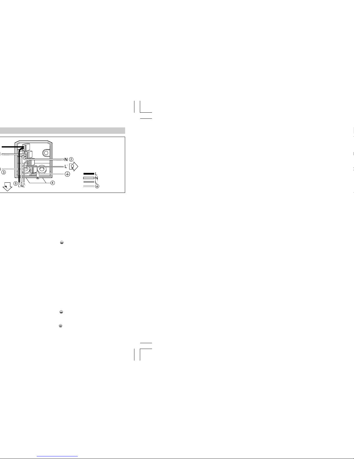
Connection of the leads:
The mains and consumer
leads consist of a 2 to 3 conductor cable:
L, L‘ =live conductor or
switched phase to
the consumer
(usually black or
brown)
N =neutral conductor
(usually blue)
PE =protective-earth
conductor,
if present ( )
If in doubt, the conductors
must be identified with a
voltage tester. Switch off the
current again.
Wiring of the mains and consumer conductors must be
performed in the wall holder
using the enclosed connecting terminals:
1. The live conductor is inserted in the first terminal (L).
2. Both neutral conductors
(N) of the mains and consumer leads are inserted into
the second terminal.
3. The switched phase to the
consumer (L‘) is inserted into
the third terminal.
4. Green/yellow protectiveearth conductors ( ) must
be inserted together into the
fourth terminal. In order to
identify the flexible leads, the
enclosed sticker ( ) must be
applied to one of the leads
(green/yellow).
Connection of the IS 300:
The connecting leads of the
IS 300 are to be inserted into
the connecting terminals according to the marking on the
leads (L = black, N = blue,
L‘ = brown).
Important: Getting the
cable connections crossed
will produce a short circuit in
the unit or in your fuse box.
In this case, you must once
again identify the individual
wires and reconnect them.
A mains switch for ON and
OFF switching can of course
be installed in the mains lead.
1) Supply lead
2) Service lead
3) Protective-earth
conductor
4) Lugs for surfacerouted supply lead
5) Connecting lead
IS 300
black
blue
brown
green/yellow
1312
Page 3
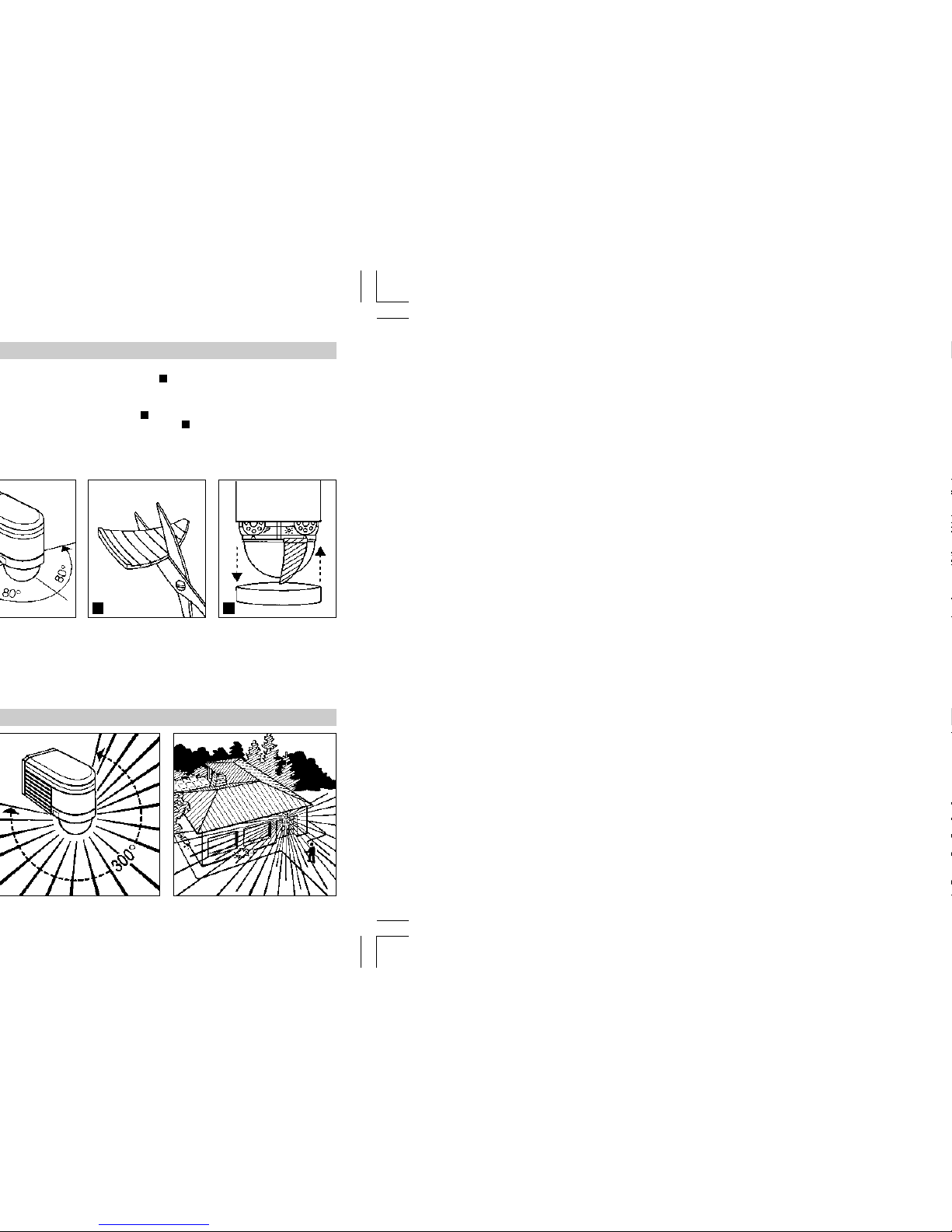
sible by turning the sensor
housing by ± 80° .
The shrouds can be divided
vertically or horizontally along
the grooved divisions, or cut
with scissors . After removing the decorative ring ,
the shrouds are to be suspended on the upper part of
the sensor lens. The decorative ring is subsequently to be
A
B
C
B
C
reapplied and the shrouds
are fixed firmly in place.
False switching by cars and
pedestrians, etc. is therefore
ruled out, or risk areas deliberately monitored.
1514
Page 4
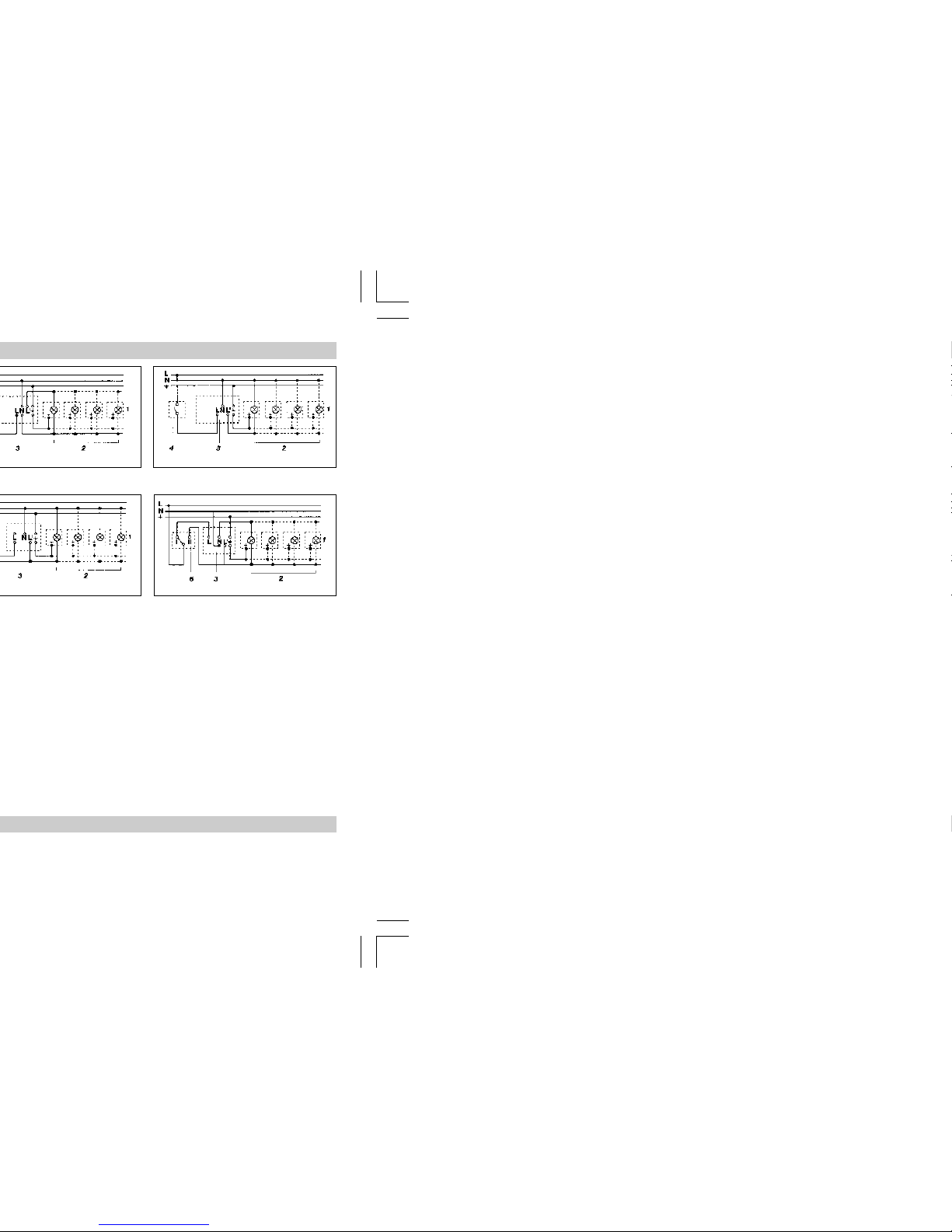
4. Connection to double-throw switch for
permanent light and automatic operation
Setting I: automatic operation
Setting II: manual operation for permanent
light
Important: the unit can not be switc hed off,
only optional operation between settings I
and II.
prescribed for this purpose.
Weather can affect operation
of the sensor. Strong gusts of
wind, snow, rain and hail can
cause switching errors, since
the sudden temperature
changes cannot be distinguished from heat sources.
The detection lens can be
cleaned with a damp cloth
(without detergents) if dirty.
1716
Page 5

max. 1000 W (uncorrected, inductive,
cos φ = 0,5, e.g. fluorescent lamps)
max. 1800 W (series corrected)
max. 500 W (parallel corrected with C = 45.6 µF)
max. 1000 W (electronic ballast, capacitive,
e.g. energy-saving lamps,
max. 12 items)
73/23/EEC and the EMC
Directive 89/336/EEC.
STEINEL undertakes the
guarantee for perfect condition and function.
The warranty period is
36 months, starting on the
date of sale to the user. We
undertake to remedy faults
caused by material or manufacturing defects. This warranty undertaking shall be
performed by the repair or replacement of the defective
parts, at our own discretion.
This warranty shall not cover
damage to wearing parts or
damage and faults caused by
incorrect operation or maintenance. Breakage due to a
fall is also not covered.
Further consequential damage to external items is excluded.
Claims under warranty shall
only be accepted if the product is sent fully assembled
and well packed complete
with sales slip or invoice
(date of purchase and dealer's stamp) to the appropriate
Service Centre or handed in
to the dealer within the first
6 months.
Repair Service:
Our Customer Service Department will repair faults not
covered by warranty or after
the warranty period. Please
send the product well packed
to your nearest Service
Centre.
1918
 Loading...