

Page 1
RUS CN BG LV LT EST HR SLO RO PL SK CZ H TR GR N FIN DK S P E I NL F GB D
STEINEL Vertrieb GmbH
Dieselstraße 80-84
33442 Herzebrock-Clarholz
Tel: +49/5245/448-188
www.steinel.de
Contact
www.steinel.de/contact
DEGBFRNLIT
Information
11005909703/2019_ATechnische Änderungen vorbehalten. / Subject to technical modification without notice.
IS 140-2 Z-Wave
Page 2
...
DE �����������8
GB �����������16
FR �����������24
NL �����������32
IT �������������40
Textteil beachten!
Follow written
instructions!
Suivre les instructions
ci-après !
Tekstpassage in
acht nemen!
Seguire attentamente
le istruzioni!
3.1
3.2
180°
3.3
86
99
91
3.5
O
L
N
I
L
N
82,4
107
3.4
A
B
C
F
D
E
90°
- 2 - - 3 -
L
N
L
N
Page 3
4.1
2 m
max 14 m
4.5
4.9
4.13
4.2
4.3
4.4
max 14 m
~ 5 m
4.6
4.7
Ø 6
4.10
4.11
Ø 5
4.8
- 4 - - 5 -
4.12
L`
N
L
4.14
4.15
I
O
5.1
(C) (E)
Page 4
5.2
5.3
5.5
180°
90°
5.4
90°
90°
90°
- 6 - - 7 -
Page 5

DE
1. Zu diesem Dokument
Bitte sorgfältig lesen und
aufbewahren!
– Urheberrechtlich geschützt.
Nachdruck, auch auszugsweise,
nur mit unserer Genehmigung.
– Änderungen, die dem technischen
Fortschritt dienen, vorbehalten.
Symbolerklärung
Warnung vor Gefahren!
!
Verweis auf Textstellen
...
im Dokument.
2. Allgemeine
Sicherheitshinweise
Vor allen Arbeiten am Gerät die
Spannungszufuhr unterbrechen!
• Bei der Montage muss die anzuschließende elektrische Leitung
spannungsfrei sein. Daher als
Erstes Strom abschalten und
Spannungsfreiheit mit einem
Spannungsprüfer überprüfen.
• Bei der Installation des Sensors
handelt es sich um eine Arbeit
an der Netzspannung. Sie muss
daher fachgerecht nach den
landesüblichen Installationsvorschriften und Anschlussbedingungen durchgeführt werden.
(z.B. DE - VDE 0100, AT - ÖVE /
ÖNORM E8001-1, CH - SEV 1000)
• Nur original Ersatzteile verwenden.
• Reparaturen dürfen nur durch
Fachwerkstätten durchgeführt
werden.
3. IS 140-2 Z-Wave
Bestimmungsgemäßer Gebrauch
– Infrarot-Bewegungsmelder für die
Auf- und Unterputzmontage im
Innen- und Außenbereich
– Sensormodul horizontal und
vertikal schwenkbar
Bewegung schaltet Licht, Alarm und
vieles mehr. Für Ihren Komfort, zu
Ihrer Sicherheit. Der eingebaute
pyro-elektrische Infrarot-Detektor
erfasst die unsichtbare Wärmestrahlung von sich bewegenden
Körpern (Menschen, Tieren, etc.).
Diese so erfasste Wärmestrahlung
wird elektronisch umgesetzt und
schaltet den angeschlossenen
Verbraucher. Durch Hindernisse, wie
z.B. Mauern oder Glasscheiben, wird
keine Wärmestrahlung erkannt, es
erfolgt also auch keine Schaltung.
Der Infrarot-Sensor eignet sich zur
automatischen Schaltung von Licht.
Für spezielle Einbruchalarmanlagen
ist das Gerät nicht geeignet, da die
hierfür vorgeschriebene Sabotagesicherheit fehlt.
Dieses Gerät kann in das Smart
Friends System oder in jedes
beliebige Z-Wave-Netzwerk integriert
werden. Z-Wave ist ein Funkstandard
zur Vernetzung von Z-Wave-Geräten.
Die Sensorgrößen des Bewegungsmelders IS 140-2 können zur
funkbasierten Gebäudeautomation
genutzt werden.
Neben zertifizierten Z-WaveControllern empfiehlt sich die Nutzung der Smart Friends-Box. Mit Hilfe
dieser SmartHome-Zentrale können
Z-Wave- Produkte von STEINEL und
die Smart Friends- Produkte von
ABUS,Paulmann und Schellenberg
vernetzt werden.
- 8 - - 9 -
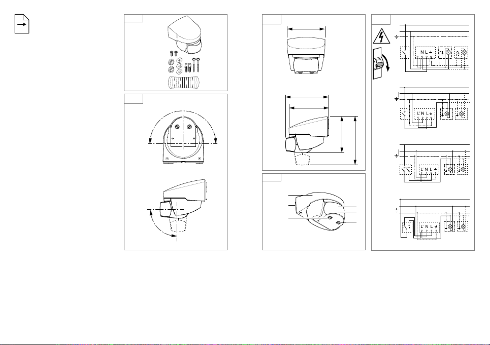
Lieferumfang (Abb.3.1)
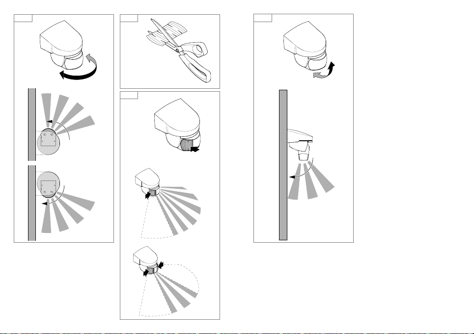
Schwenkbereich Sensor
(Abb.3.2/5.2/5.5)
Produktmaße (Abb.3.3)
Geräteübersicht (Abb.3.4)
A Sensorgehäuse
B Wandhalter
C Einstellregler Dämmerungs-
einstellung
D Sensoreinheit
E Z-Wave Drehregler
F Status-LED
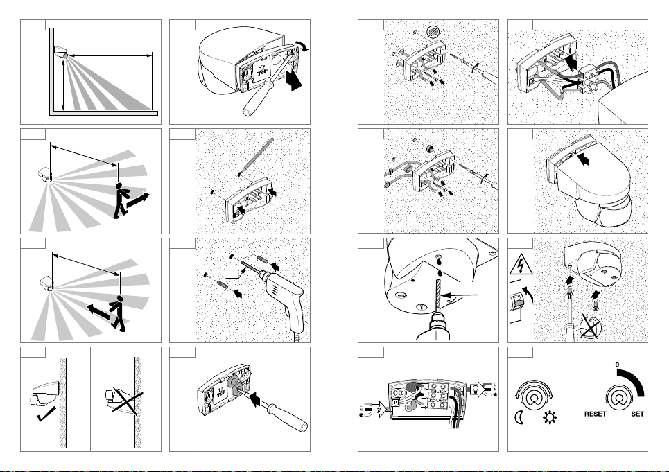
Reichweite (Abb.4.1)
4. Elektrische Installation
• Stromversorgung abschalten
(Abb.3.5)
Anschluss Netzzuleitung
Die Netzzuleitung besteht aus einem
3-adrigen Kabel:
L = Phase (meistens schwarz
oder braun)
N = Neutralleiter (meistens blau)
PE = Schutzleiter (meistens grün/
gelb)
Im Zweifel müssen Sie die Leitungen mit einem Spannungsprüfer
identifizieren; anschließend wieder
spannungsfrei schalten. Schutzleiter
bei Bedarf durchschleifen.
Wichtig: Ein Vertauschen der
Anschlüsse führt im Ge rät oder Ihrem
Sicherungs ka sten später zum Kurzschluss. In diesem Fall müssen die
einzelnen Leitungen identifiziert und
neu montiert werden. In die Netzzuleitung kann ein geeigneter Netz schalter
zum EIN- und AUS-Schalten montiert
sein. Der Stromkreis muss mit einem
10A-Leitungsschutzschalter abgesichert werden.
Anschlusszeichnung (Abb.3.5)
5. Montage
• Alle Bauteile auf Beschädigung
prüfen.
• Bei Schäden das Produkt nicht in
Betrieb nehmen.
• Geeigneten Montageort unter
Berücksichtigung der Reichweite
und Bewegungserfassung
auswählen (Abb.4.1). Die
sicherste Bewegungserfassung
wird erreicht, wenn der Sensor
seitlich zur Gehrichtung montiert
bzw. ausgerichtet wird und keine
Hindernisse (wie z.B. Bäume,
mauern etc.) die Sicht behindern.
(Abb.4.2/4.3)
Montageschritte
• Stromversorgung abschalten.
• Gehäuse (A) vom Wandhalter (B)
lösen. (Abb.4.5)
• Bohrlöcher anzeichnen. (Abb.4.6)
• Löcher bohren und Dübel
einsetzen. (Abb.4.7)
• Dichtstopfen einsetzen. (Abb.4.8)
– Zuleitung Unterputz (Abb.4.9)
– Zuleitung Aufputz mit Abstands-
haltern (Abb.4.10)
• Kondenzwasserloch mit einem
5mm Bohrer bohren. (Abb.4.11)
• Anschlusskabel anschließen.
(Abb.4.12/4.13)
• Gehäuse auf Wandhalter
aufstecken. (Abb.4.14)
• Sicherungsschrauben
einschrauben. (Abb.4.15)
• Stromversorgung einschalten.
(Abb.4.15)
• Funktionseinstellungen vornehmen
➜ "6. Funktion".
Page 6
6. Funktion
Der Bewegungsmelder funktioniert
auch ohne Einbindung in ein Z-WaveNetzwerk. Dabei ist die Zeiteinstellung
fest auf 3 Minuten eingestellt. Der
Bewegungsmelder ist nach der Einmessphase von 10Sekunden für den
Sensorbetrieb aktiv. Nun kann der
Bewegungsmelder in das Z-WaveNetzwerk integriert werden.
Die Einstellungen können über Drehregler oder per Z-Wave-Netzwerk
vorgenommen werden. Es gelten
immer die zuletzt eingestellten Werte,
unabhängig davon, ob die Einstellung
über die Drehregler oder per Z-WaveNetzwerk erfolgte.
Werkseinstellungen
Dämmerungseinstellung (C):
2000Lux
Zeiteinstellung: 3 min
Dämmerungseinstellung
(Abb.5.1/C) stufenlos einstellbar
Einstellregler auf
betrieb ca. 2 Lux
Einstellregler auf
betrieb ca. 2000 Lux
Hinweis: Bei Einstellung des Erfassungsbereiches bei Tageslicht ist der
Einstellregler auf
trieb zu stellen.
Reichweiteneinstellung/Justierung
Je nach Bedarf kann der Erfassungsbereich optimal eingestellt werden.
Sensoreinheit
– Schwenken der Sensoreinheit
horizontal 180°. (Abb.5.2)
– Kippen der Sensoreinheit vertikal
90°. (Abb.5.5)
Abdeckaufkleber (Abb.5.3)
Die Abdeckfolie dient dazu, beliebig
viele Linsensegmente abzudecken
= Dämmerungs-
= Tageslicht-
= Tageslichtbe-
und somit die Reichweite individuell
einzuschränken. Fehlschaltungen
werden ausgeschlossen oder
Gefahrenstellen gezielt überwacht.
(Abb.5.4)
7. Integration in Z-WaveNetzwerke
Dieses Produkt kann in allen
Z-Wave-Netzwerken mit zertifizierten
Z-Wave-Vorrichtungen anderer
Hersteller betrieben werden. Alle
nicht batteriebetriebenen Netzknoten
im Netzwerk wirken als Verstärker - unabhängig vom jeweiligen
Anbieter - um die Zuverlässigkeit des
Netzwerkes zu erhöhen.
Inklusion Hinzufügen
Exklusion Entfernen
Diese Anleitung zur Inklusion und
Exklusion von STEINEL Z-WaveProdukten ist für das Smart Friends
System geschrieben. Bei anderen
Z-Wave-Produkten kann dies abweichen. Weitere Details dazu finden Sie
in der Beschreibung ihres Z-WaveControllers. (Um den Inklusions- oder
Exklusionsmodus des Bewegungsmelders zu starten, den Drehregler
des Geräts (E) auf "Set" drehen und
innerhalb von 5 Sekunden zurück auf
"0" drehen).
Nach der Exklusion bleiben alle Konfigurationsparameter (Zeit, Sensitivität
usw.) bis zur nächsten Inklusion
erhalten und die Leuchte arbeitet nun
im Standalone-Modus - daher kann
Z-Wave auch für die StandaloneEinstellung der Leuchte verwendet
werden.
- 10 - - 11 -
Z-Wave-Drehregler (E)
IS 140-2 dem Smart Friends
System hinzufügen:
1 Smart Friends App aus dem App
Store herunterladen.
2 In der Ansicht Räume den Bearbei-
tungsmodus aktivieren.
3 Wählen Sie den gewünschten
Raum aus und drücken Sie den
Button "Gerät hinzufügen".
4 Drehregler des Geräts (E) auf "Set"
drehen und innerhalb von 5 Sekunden zurück auf "0" drehen, um den
Strahler in den Inklusionsmodus zu
bringen. Dieser Modus wird durch
das Leuchten der Status-LED (F)
angezeigt.
5 Nach erfolgreicher Inklusion erfolgt
eine Bestätigungsnachricht in der
App.
IS 140-2 aus Smart Friends
System entfernen:
1 In der Ansicht Räume den
Bearbeitungsmodus aktivieren.
Drehregler zur
Inklusion und
Exklusion sowie zum
Zurücksetzen des
Geräts in
Werkseinstellung.
2. Wählen Sie im gewünschten Raum
das Gerät aus und drücken Sie den
"delete"
Button. Drücken Sie
auf löschen und folgen Sie den
Anweisungen in der App.
3 Drehregler des Geräts (E) auf "Set"
drehen und innerhalb von 5 Sekunden zurück auf "0" drehen, um den
Strahler in den Exklusionsmodus zu
bringen. Dieser Modus wird durch
das Leuchten der roten Status-LED
(F) angezeigt.
4 Nach erfolgreicher Exklusion
erfolgt eine Bestätigungsnachricht
in der App.
IS 140-2 mit der App einstellen
– Nach dem Anlernen wird in der
App automatisch eine An-/AusSzene angelegt
– Folgende Einstellungswerte sind
dann automatisch hinterlegt:
a) Dämmerungseinstellung =
Einstellung des Drehreglers
b) Zeiteinstellung =
3 min Ausschaltverzögerung
– in dem Menü "Szene" können die
Dämmerungs- und Zeiteinstellungen lux- bzw. sekundengenau
eingestellt werden.
IS 140-2 auf Werkseinstellungen
zurücksetzen:
Bitte führen Sie diese Schritte nur
durch, wenn der Netzwerk-Hauptregler fehlt oder aus anderen Gründen
nicht funktionsfähig ist.
1 Drehregler des Geräts (E) auf "Set"
drehen und innerhalb von 5Sekunden auf "Reset" stellen.
2 Der Reset wird durch Blinken der
Status-LED (F) angezeigt.
3 Das Gerät ist nun nicht mehr im
Z-Wave-System inkludiert und ist
auf Werkseinstellung zurückgesetzt.
Page 7
3
5
HERSTELLER
GARANTIE
Hinweis: Die derzeitige FirmwareVersion für die Leuchte können Sie
unter z-wave.steinel.de herunterladen.
8. Betrieb/Pflege
Witterungseinflüsse können die
Funktion des Bewegungsmelders
beeinflussen, bei starken Windböen,
Schnee, Regen, Hagel kann es zu
einer Fehlschaltung kommen, da
die plötzlichen Temperaturschwankungen nicht von Wärmequellen
unterschieden werden können. Die
Erfassungslinse kann bei Verschmutzung mit einem feuchten Tuch (ohne
Reinigungsmittel) gesäubert werden.
9. EG-Konformitätserklärung
Hiermit erklärt STEINEL Vertrieb
GmbH, dass der Funkanlagentyp
IS140-2Z-Wave der Richtlinie
2014/53/EU entspricht. Der vollständige Text der EU-Konformitätserklärung ist unter der folgenden
Internetadresse verfügbar:
www.steinel.de
10. Entsorgung
Elektrogeräte, Zubehör und Verpackungen sollen einer umweltgerechten Wiederverwertung zugeführt
werden.
Werfen Sie Elektrogeräte
nicht in den Hausmüll!
Nur für EU-Länder:
Gemäß der geltenden Europäischen
Richtlinie über Elektro- und Elektronik-Altgeräte und ihrer Umsetzung
in nationales Recht müssen nicht
mehr gebrauchsfähige Elektrogeräte getrennt gesammelt und einer
umweltgerechten Wiederverwertung
zugeführt werden.
11. Herstellergarantie
Herstellergarantie
der STEINEL Vertrieb GmbH,
Dieselstraße 80-84,
33442 Herzebrock-Clarholz
Wir beglückwünschen Sie zum Kauf
Ihres STEINEL-Produkts, das höchste
Qualitätsansprüche erfüllt. Aus diesem Grund leisten wir als Hersteller
Ihnen als Endkunde gerne eine unentgeltliche Garantie gemäß den nachstehenden Bedingungen: Wir leisten
Garantie durch kostenlose Behebung
der Mängel (nach unserer Wahl:
Reparatur, Austausch ggf. durch ein
Nachfolgemodell oder Rückerstattung
des Kaufpreises), die innerhalb der
Garantiezeit auf einem Materialoder Herstellungsfehler beruhen.
Die Garantiezeit für Ihr erworbenes
STEINEL-Produkt beträgt 3 Jahre und
beginnt mit dem Kaufdatum Ihres
Produktes. Diese Herstellergarantie
lässt gesetzliche Gewährleistungsansprüche, die Ihnen als Verbraucher
gegenüber dem Verkäufer nach
geltendem Recht einschließlich
besonderer Schutzbestimmungen
für Verbraucher zustehen können,
unberührt. Die hier beschriebenen
Leistungen gelten zusätzlich zu den
gesetzlichen Gewährleistungsansprüchen und beschränken oder ersetzen
diese nicht.
Ausdrücklich ausgenommen von
dieser Garantie sind alle auswechselbaren Leuchtmittel. Darüber hinaus ist
die Garantie ausgeschlossen:
- 12 - - 13 -
• bei einem gebrauchsbedingten oder sonstigen natürlichen
Verschleiß von Produktteilen oder
Mängeln am STEINEL-Produkt,
die auf gebrauchsbedingtem oder
sonstigem natürlichem Verschleiß
zurückzuführen sind,
• bei nicht bestimmungs- oder
unsachgemäßem Gebrauch des
Produkts oder Missachtung der
Bedienungshinweise,
• wenn An- und Umbauten bzw.
sonstige Modifikationen an dem
Produkt eigenmächtig vorgenommen wurden oder Mängel auf
die Verwendung von Zubehör-,
Ergänzungs- oder Ersatzteilen
zurückzuführen sind, die keine
STEINEL-Originalteile sind,
• wenn Wartung und Pflege der
Produkte nicht entsprechend der
Bedienungsanleitung erfolgt sind,
• wenn Anbau und Installation nicht
gemäß den Installationsvorschriften
von STEINEL ausgeführt wurden,
• bei Transportschäden oder
-verlusten.
Die Garantie gilt für sämtliche
STEINEL- Produkte, die in Deutschland gekauft und verwendet werden.
Es gilt deutsches Recht unter
Ausschluss des Übereinkommens
der Vereinten Nationen über Verträge
über den internationalen Warenkauf
(CISG).
Geltendmachung
Wenn Sie Ihr Produkt reklamieren
wollen, senden Sie es bitte vollständig
und frachtfrei mit dem OriginalKaufbeleg, der die Angabe des Kaufdatums und der Produktbezeichnung
enthalten muss, an Ihren Händler
oder direkt an uns, die STEINEL
Vertrieb GmbH – Reklamationsabteilung –, Dieselstraße 80-84, 33442
Herzebrock-Clarholz. Wir empfehlen
Ihnen daher, Ihren Kaufbeleg bis zum
Ablauf der Garantiezeit sorgfältig aufzubewahren. Für Transportkosten und
-risiken im Rahmen der Rücksendung
übernehmen wir keine Haftung.
HERSTELLER
GARANTIE
Page 8
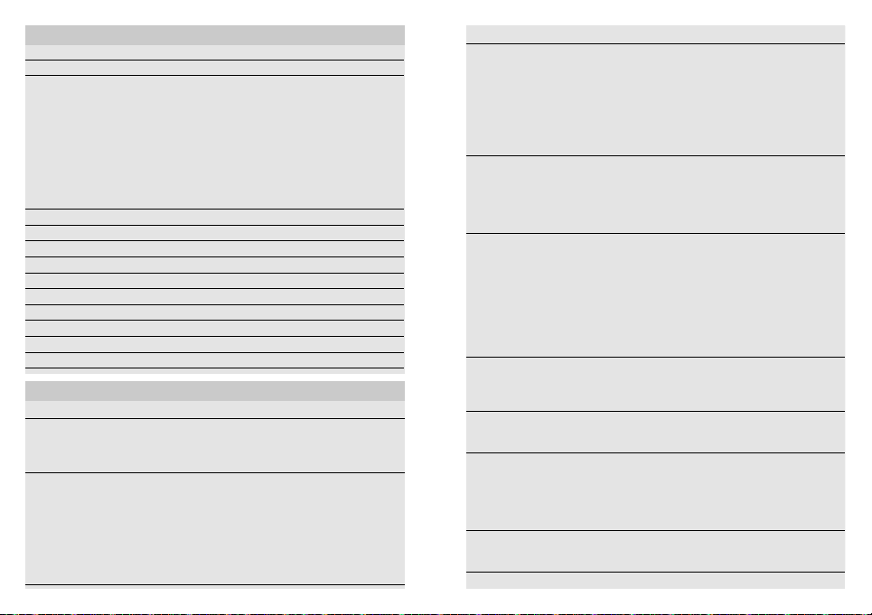
12. Technische Daten
Abmessungen H × B ×T 70 × 86 × 95 mm
Netzanschluss 230 - 240 V, 50 Hz
Leistung
Leuchtstoampen reihenkompensiert
Leuchtstoampen parallelkompensiert
Sensortechnik Passiv-Infrarot
Erfassungswinkel 140° mit Unterkriechschutz
Reichweite max. 14 m (temperaturstabilisiert) über Drehregler
Zeiteinstellung 3 min. Werkseinstellung / 1 s bis 15 min mit der App
Dämmerungseinstellung 2-2000 Lux über Drehregler und mit der App
Schutzart IP 54
Temperaturbereich - 20 °C bis + 50 °C
Z-Wave Funkreichweite ca. 100 m (Freifeld)
Funkfrequenzband 868 MHz
Sendeleistung ≤ 2,5 mW
Glüh-/Halogenlampenlast
Leuchtstoampen EVGs
Leuchtstoampen unkompensiert
Niedervolt-Halogenlampen
LED < 2 W
2 W < LED < 8 W
LED > 8 W
Kapazitive Belastung
1000 W
430 W
500 VA
500 VA
500 VA
1000 VA
16 W
64 W
64 W
132 μF
13. Betriebsstörungen
Störung Ursache Abhilfe
Ohne Spannung
Schaltet nicht ein
n Sicherung defekt,
nicht eingeschaltet
n Kurzschluss
n bei Tagesbetrieb, Dämme-
rungseinstellung steht auf
Nachtbetrieb
n Glühlampe defekt
n Netzschalter AUS
n Sicherung defekt
n Erfassungsbereich nicht
gezielt eingestellt
- 14 - - 15 -
n neue Sicherung, Netz schalter
einschalten, Leitung überprüfen mit Spannungsprüfer
n Anschlüsse überprüfen
n neu einstellen
n Glühlampen austauschen
n einschalten
n neue Sicherung, evtl.
Anschluss überprüfen
n neu justieren
Störung Ursache Abhilfe
Schaltet
nicht aus
Schaltet
immer
EIN / AUS
Schaltet
unerwünscht ein
Das Gerät lässt
sich nicht hinzufügen (und ist noch
nicht hinzugefügt)
Das Gerät lässt
sich nicht
hinzufügen
Status-LED
(F) blinkt alle
5Sekunden für
1Sekunde auf
Status-LED (F)
blinkt schnell und
durchgängig
n dauernde Bewegung im
Erfassungsbereich
n geschaltete Leuchte befindet
sich im Erfassungsbereich
und schaltet durch Temperaturveränderung neu
n durch den hausinternen
Serien schalter auf Dauerbetrieb
n geschaltete Leuchte befindet
sich im Erfassungsbereich
n Tiere bewegen sich im
Erfassungsbereich
n Wind bewegt Bäume und
Sträucher im Erfassungsbereich
n Erfassung von Autos auf der
Straße
n plötzliche Temperatur-
veränderung durch Witterung
(Wind, Regen, Schnee)
oder Abluft aus Ventilatoren,
oenen Fenstern
n zu große Entfernung
zwischen Z-Wave
Controller und Gerät
n es ist bereits hinzugefügt n Gerät aus bestehendem
n kein Funkkontakt zur Smart
Friends Box oder anderen
Z-Wave-Controller
n kritischer Fehler n Gerät kurzzeitig von der
n Bereich kontrollieren und evtl.
neu justieren bzw. abdecken
n Bereich kontrollieren
n Serienschalter auf Automatik
n Bereich kontrollieren
n Bereich kontrollieren. Sensor
höher schwenken bzw. gezielt
abdecken; Bereich umstellen,
bzw. abdecken
n Bereich kontrollieren
n Bereich kontrollieren
n Bereich verändern,
Montageort verlegen
n Entfernung zu Z-Wave-
Controller verringern
n Einbau eines Z-Wave-
Repeaters
Netzwerk entfernen
n Default Reset durchführen
n Smart Friends Box oder
Z-Wave-Controller neustarten
n Entfernung zu Z-Wave-
Controller verringern
n Einbau eines Z-Wave-
Repeaters
Netzspannung trennen
Page 9
GB
!
1. About this document
Please read carefully and keep in a
safe place.
– Under copyright. Reproduction
either in whole or in part only with
our consent.
– Subject to change in the interest
of technical progress.
Symbols
Hazard warning!
Reference to other
...
information in the document.
2. General safety
precautions
Disconnect the power supply
before attempting any work on
the unit.
• During installation, the electric
power cable being connected
must not be live. Therefore, switch
o the power first and use a voltage tester to make sure the wiring
is o-circuit.
• Installing the sensor involves work
on the mains power supply. This
work must therefore be carried
out correctly in accordance with
applicable national wiring regulations and electrical operating
conditions. (e.g. DE - VDE 0100,
AT - ÖVE / ÖNORM E8001-1,
CH - SEV 1000)
• Only use genuine replacement
parts.
• Repairs may only be made by
specialist workshops.
3. IS 140-2 Z-Wave
Proper use
– Infrared motion detector for indoor
and outdoor surface-mounted and
concealed installation
– Sensor module swivels and tilts
Movement triggers lights, alarms and
many other devices. For your convenience, safety and peace of mind.
The integrated pyroelectric infrared
detector senses the invisible heat
radiated from moving objects (people,
animals, etc.). The heat detected in
this way is converted electronically
into a signal that switches ON the
connected load. Heat is not detected
through obstacles, such as walls or
panes of glass, and will therefore not
activate the light. The infrared sensor
can be used for switching light ON
and OFF automatically. The unit is not
suitable for burglar alarm systems as
it is not tamperproof in the manner
prescribed for such systems.
This device can be integrated into
the Smart Friends system or any
other Z-Wave network. Z-Wave is a
wireless standard for interconnecting
Z-Wave devices. The sensor parameters of the IS 140-2 motion detector can be used for wireless-based
building automation.
Besides certified Z-Wave controllers,
it is recommended to use the Smart
Friends box. This smart-home control
centre can be used for interconnecting Z-Wave products from STEINEL
and the Smart Friends products from
ABUS, Paulmann and Schellenberg.
Package contents (Fig. 3.1)
Sensor adjustment range
(Fig.3.2 / 3.3 / 5.6)
Product dimensions (Fig.3.3)
- 16 - - 17 -
Product components (Fig. 3.4)
Sensor enclosure
Wall mount
Twilight setting control dial
Sensor unit
Z-Wave control dial
Status LED
Reach (Fig.4.1)
4. Electrical installation
• Switch OFF power supply
(Fig.3.5)
Connecting the mains supply lead
The mains leads consists of at least a
3-core cable:
L = Phase conductor
(usually black or brown)
N = Neutral conductor
(usually blue)
PE = Protective-earth conductor
(usually green/yellow)
If you are in any doubt, identify the
conductors using a voltage tester;
then disconnect from the power
supply again. Loop through any
protective-earth conductor.
Important: incorrectly wired connections will produce a short circuit
later on in the product or your fuse
box. In this case, you must identify
the individual leads and reconnect
them. An appropriate power switch
for switching ON and OFF can be installed in the supply lead. The electric
circuit must be protected by a 10A
circuit breaker.
Connection diagram (Fig.3.5)
5. Mounting
• Check all components for
damage.
• Do not use the product if it is
damaged.
• Select an appropriate mounting
location, taking the reach and
motion detection into consideration (Fig.4.1). The most reliable
way of detecting movement is to
install the sensor aimed across
the direction in which a person
would walk and by ensuring that
no obstacles (such as trees, walls
etc.) obstruct the line of sensor
vision. (Fig.4.2 / 4.3)
Mounting procedure
• Switch OFF power supply.
• Detach enclosure
mount
• Mark drill holes. (Fig.4.6)
• Drill holes and fit wall plugs.
(Fig.4.7)
• Fit sealing plug. (Fig.4.8)
– Concealed power supply lead
(Fig.4.9)
– Concealed power supply lead
with spacers (Fig.4.10)
• Drill condensation water drainage
hole with a 5mm drill bit.
(Fig.4.11)
• Connect conductors.
(Fig.4.12 / 4.13)
• Fit enclosure onto wall mount.
(Fig.4.14)
• Screw in retaining screws.
(Fig.4.15)
• Switch ON power supply.
(Fig.4.15)
• Set functions
. (Fig.4.5)
"6. Function"
from wall
Page 10
6. Function
The motion detector will also work
without being integrated into a
Z-Wave network. In this case, the
time setting is permanently set to
3minutes. When putting the motion
detector into operation, it will switch
OFF after the 10-second calibration
phase and is then activated for sensor mode. The motion detector can
now be integrated into the Z-Wave
network.
The settings can be made via the
control dials or via Z-Wave network.
The settings last selected will always
be in eect regardless of whether
they were made via the control dials
or via Z-Wave network.
Factory settings
Twilight level
Time setting: 3 min
Twilight setting (Fig.5.1/C)
can be infinitely varied
Control dial set to
twilight operation, approx. 2 lux
Control dial set to
daylight operation, approx. 2000 lux
Note: To adjust the detection zone in
daylight, the control dial must be set
to
Reach setting/adjustment
The detection zone can be optimised
to suit requirements.
Sensor unit
– Sensor unit swivels through 180°.
(Fig.5.2)
– Sensor unit tilts through 90°.
(Fig.5.5)
Adhesive shrouds (Fig.5.3)
The film shroud can be used for
masking out any number of lens
: 2000lux
=
=
= daylight operation.
segments to limit reach as required.
Inadvertent triggering is ruled out or
the sensor can be targeted to watch
over danger spots. (Fig.5.4)
7. Integration into Z-Wave
networks
This product can be operated in any
Z-Wave network with other Z-Wave
certified devices from other manufacturers. All non-battery operated
nodes within the network will act as
repeaters regardless of vendor to
increase reliability of the network.
Inclusion Add
Exclusion Remove
These instructions for including and
excluding STEINEL Z-Wave products
have been written for the Smart
Friends system. They may not always
apply to other Z-Wave products. You
will find further details in the description of your Z-Wave controller. (To
start the motion detector's inclusion
or exclusion mode, turn the device's
control dial
"0" within 5seconds).
Following exclusion, all configuration
parameters (time, sensitivity etc.)
remain intact until next inclusion and
the light now works in standalone
mode – as a result, Z-Wave can also
be used for the light’s standalone
setting.
- 18 - - 19 -
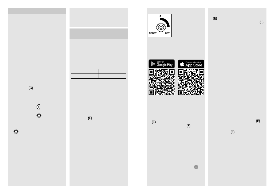
to "Set" and back to
Z-Wave control dial (E)
Adding IS 140-2 to the
Smart Friends system:
1 Download Smart Friends app from
the app store.
2 In the rooms view, activate the
edit mode.
3 Select the chosen room and press
the "Add device" button.
4 To put the device into inclusion
mode, turn the device's control dial
to "Set" and back to "0" within
5seconds. Status LED
to show that this mode is selected.
5 The app displays a confirmation
message once inclusion has been
successfully completed.
Removing IS 140-2 from the
Smart Friends system:
1 In the rooms view, activate the
edit mode.
2 Select the device in the chosen
room and press the "delete"
button. Press delete and follow the
instructions in the app.
Control dial for
inclusion and
exclusion as well as
for returning the
device to the factory
setting.
lights up
3 To put the device into exclusion
mode, turn the device's control dial
to "Set" and back to "0" within
5seconds. The red status LED
lights up to show that this mode is
selected.
4 The app displays a confirmation
message once exclusion has been
successfully completed.
Setting IS 140-2 with the app
– After programming, an ON/OFF
scene is automatically created in
the app.
– The following setting values are
then automatically stored:
a) Twilight setting = control-dial
setting
b) Time setting = 3 min switch-
OFF delay
– The twilight and time settings can
be selected to the accuracy of a
lux / second in the "Scene" menu.
Resetting the IS 140-2 to factory
settings:
Please only perform these steps if the
main network controller is missing or
not working for other reasons.
1 Turn the device's control dial
"Set" and move it to "Reset" within
5 seconds.
2 Status LED
show that the light has been reset.
3 The device is now no longer includ-
ed in the Z-Wave system and has
been reset to factory settings.
Note: the current firmware version for
the light is available for downloading
from z-wave.steinel.de.
briefly flashes to
to
Page 11
8. Operation/maintenance
3
5
MANUFACTURER'S
YEAR
WARRANTY
Weather conditions may aect the
way the motion detector works.
Strong gusts of wind, snow, rain or
hail may cause the light to come
ON when it is not wanted because
the sensor is unable to distinguish
between sudden changes of temperature and sources of heat. The
detector lens may be cleaned with a
damp cloth if it gets dirty (do not use
cleaning agents).
9. EC Declaration of
Conformity
Hereby, STEINEL Vertrieb GmbH
declares that the radio equipment
type IS140-2Z-Wave is in compliance with Directive 2014/53/EU.
The full text of the EU declaration of
conformity is available at the following
internet address: www.steinel.de
10. Disposal
Electrical and electronic equipment,
accessories and packaging must
be recycled in an environmentally
compatible manner.
Do not dispose of electrical
and electronic equipment as
domestic waste.
EU countries only:
Under the current European Directive
on Waste Electrical and Electronic
Equipment and its implementation in
national law, electrical and electronic
equipment no longer suitable for
use must be collected separately
and recycled in an environmentally
compatible manner.
11. Manufacturer’s Warranty
This STEINEL product has been
manufactured with utmost care,
tested for proper operation and
safety and then subjected to random
sample inspection. Steinel guarantees
that it is in perfect condition and
proper working order. The warranty
period is 36 months and starts on
the date of sale to the consumer.
We will remedy defects caused by
material flaws or manufacturing faults.
The warranty will be met by repair or
replacement of defective parts at our
own discretion. The warranty shall not
cover damage to wear parts, damage
or defects caused by improper
treatment or maintenance. Further
consequential damage to other
objects shall be excluded.
Claims under the warranty will only
be accepted if the unit is sent fully
assembled and well-packed with a
brief description of the fault, a receipt
or invoice (date of purchase and
dealer's stamp) to the appropriate
Service Centre.
Service:
Our Customer Service Department
will repair faults not covered by
warranty or after the warranty period
has expired. Please send the product
well-packed to your nearest Service
Centre.
YEAR
MANUFACTURER'S
WARRANTY
12. Technical specifications
Dimensions H×W×D 70 × 86 × 95 mm
Mains power supply 230-240 V, 50 Hz
Output
Incandescent / halogen lamp load
Fluorescent lamps, electronic ballast
Fluorescent lamps, uncorrected
Fluorescent lamps, series-corrected
Fluorescent lamps, parallel-corrected
Low-voltage halogen lamps
Sensor technology Passive infrared
Angle of coverage 140° with sneak-by guard
Reach max. 14 m (temperature-stabilised)
Time setting 3 min. factory setting /
Twilight setting 2-2000 lux via control dial and
IP rating IP54
Temperature range -20°C to +50°C
Z-Wave wireless range approx. 100 m
Radio frequency band 868 MHz
Transmitter power ≤ 2.5 mW
LED < 2 W
2 W < LED < 8 W
LED > 8 W
Capacitive load
1000 W
430 W
500 VA
500 VA
500 VA
1000 VA
16 W
64 W
64 W
132 μF
via control dial
1 s to 15 min with the app
with the app
(unobstructed line of vision)
- 21 -- 20 -
Page 12
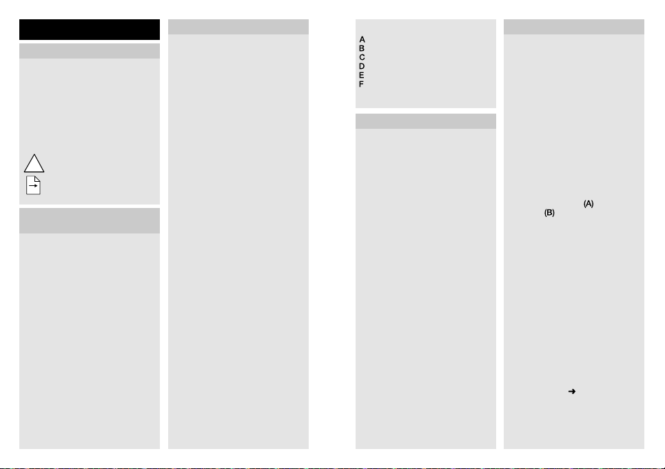
13. Troubleshooting
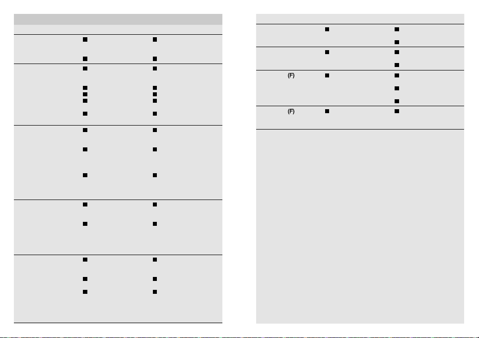
Malfunction Cause Remedy
Without power
Does not switch ON
Does not switch OFF
Keeps switching
ON / OFF
Switches ON when it
should not
Fuse faulty,
not switched ON
Short-circuit
Twilight setting in
night-time mode during
daytime operation
Bulb faulty
Mains switch OFF
Fuse faulty
Detection zone not
correctly adjusted
Continued movement
within the detection
zone
Light is in detection
zone and keeps switch-
ing ON as a result of
temperature change
Set to continuous
operation via indoor
two-circuit single
interruption switch
Light being operated is
located in the detection
zone
Animals moving in the
detection zone
Wind is moving trees and
bushes in the detection
zone
Cars in the street are
being detected
Sudden temperature
changes due to weather
(wind, rain, snow) or air
expelled from fans or
open windows
- 22 - - 23 -
New fuse, turn ON
power switch, check
wiring with voltage tester
Check connections
Reset
Replace light bulbs
Switch ON
Replace fuse, check
connection if necessary
Readjust
Check zone and readjust
if necessary or apply
shroud
Check detection zone
Set two-circuit single
interruption switch to
automatic operation
Check detection zone
Check detection zone.
Tilt sensor higher or
fit shrouds to target
sensor; adjust detection
zone or fit shrouds
Check detection zone
Check detection zone
Adjust detection zone or
install in a dierent place
Malfunction Cause Remedy
The device cannot be
added (and is not yet
added)
The device cannot be
added
Status LED
for 1 second every
5seconds
Status LED
rapidly all the time
flashing
flashing
Z-Wave controller
too far from the
device
It is already added Remove device from
No wireless contact with
the Smart Friends box or
other Z-Wave controller
Critical fault Briefly disconnect device
Reduce distance from
Z-Wave controller
Install a Z-Wave repeater
existing network
Carry out default reset
Re-start Smart Friends
box or Z-Wave controller
Reduce distance from
Z-Wave controller
Install a Z-Wave repeater
from the mains power
supply
Page 13
FR
!
1. À propos de ce document
Veuillez le lire attentivement et le
conserver en lieu sûr !
– Il est protégé par la loi sur les droits
d'auteur. Une réimpression même
partielle n'est autorisée qu'après
notre accord préalable.
– Sous réserve de modifications
techniques.
Explication des symboles
Attention danger !
Renvoi à des passages
...
dans le document.
2. Consignes de sécurité
générales
Avant toute intervention sur l'appareil, couper l'alimentation électrique !
• Pendant le montage, les conducteurs à raccorder doivent être hors
tension. Il faut donc d'abord couper
le courant et s'assurer de l'absence
de courant à l'aide d'un testeur de
tension.
• L'installation du détecteur implique
une intervention sur le réseau électrique et doit donc être eectuée
correctement et conformément à la
norme NFC-15100. (Par ex.
DE - VDE 0100, AT - ÖVE/
ÖNORM E8001-1, CH - SEV 1000)
• Utiliser uniquement des pièces de
rechange d'origine.
• Les réparations ne doivent être
eectuées que par des ateliers
spécialisés.
3. IS 140-2 Z-Wave
Utilisation conforme aux prescriptions
– Détecteur de mouvement à infra-
rouge pour montage en saillie ou
encastré à l'intérieur et à l'extérieur
– Module de détection orientable à
l'horizontale et à la verticale
Pour votre confort et votre sécurité,
le mouvement allume la lumière,
déclenche une alarme, etc. Le détecteur infrarouge pyroélectrique intégré
détecte le rayonnement de chaleur invisible émis par les corps en mouvement
(personnes, animaux, etc.).
Ce rayonnement de chaleur capté est
ensuite traité par un système électronique qui enclenche le consommateur
branché. Les obstacles comme les
murs ou les vitres s'opposent à la
détection du rayonnement de chaleur
et empêchent toute commutation.
Le détecteur infrarouge est conçu
pour la commutation automatique de
l'éclairage. Il n'est toutefois pas prévu
pour les alarmes spéciales anti-intrusion car il n'est pas protégé contre le
vandalisme.
Il est possible d'intégrer cet appareil
dans le système Smart Friends ou dans
n'importe quel réseau Z-Wave. Z-Wave
est un protocole radio permettant
de mettre des appareils Z-Wave en
réseau. Il est possible d'utiliser les données du détecteur de mouvement IS
140-2 pour l'automation de bâtiments
basée sur un protocole radio.
Outre les contrôleurs Z-Wave certifiés,
il est recommandé d'utiliser le Smart
Friends Box. La centrale SmartHome
permet de mettre en réseau des
appareils Z-Wave de STEINEL et des
appareils Smart Friends de ABUS,
Paulmann et Schellenberg.
- 24 - - 25 -
Contenu de la livraison (fig. 3.1)
Orientabilité du détecteur
(fig. 3.2/5.2/5.5)
Dimensions de l'appareil (fig. 3.3)
Vue d'ensemble de l'appareil (fig. 3.4)
Boîtier du détecteur
Support mural
Bouton de réglage de la luminosité
de déclenchement
Détecteur
Bouton de réglage Z-Wave
LED d'état
Portée (fig. 4.1)
4. Installation électrique
• Couper l'alimentation en courant
(fig.3.5)
Branchement du câble secteur
Le câble secteur est composé d'un
câble à 3 conducteurs :
L = phase
(généralement noir ou marron)
N = neutre (généralement bleu)
PE = conducteur de terre
(généralement vert/jaune)
En cas de doute, il faut identifier les
câbles avec un testeur de tension, puis
les remettre hors tension. Boucler la
terre si nécessaire.
Important : une inversion des
branchements entraînera plus tard un
court-circuit dans l'appareil ou dans le
boîtier à fusibles. Dans ce cas, il faut
identifier les câbles et les raccorder en
conséquence. Il est possible de monter
sur le câble secteur un interrupteur
adéquat permettant la mise en ou hors
circuit de l'appareil. Le circuit électrique
doit être protégé par un disjoncteur de
protection de ligne de 10 A.
Schéma de connexion (fig. 3.5)
5. Montage
• Contrôler l'absence de dommages
sur toutes les pièces.
• Ne pas mettre l'appareil en service
en cas de dommage.
• Choisir un emplacement de montage approprié en tenant compte
de la portée et de la détection des
mouvements (fig. 4.1). La détection
des mouvements est la plus fiable
quand le détecteur est monté ou
orienté perpendiculairement au
sens de passage et qu'aucun
obstacle (arbre, mur, etc.) n'obstrue
le champ de visée. (fig.4.2/4.3)
Étapes de montage
• Couper l'alimentation électrique.
• Enlever le boîtier
mural
• Marquer l'emplacement des trous.
(fig.4.6)
• Percer les trous, puis mettre les
chevilles. (fig.4.7)
• Mettre le bouchon. (fig.4.8)
– Câble d'alimentation encastré
(fig.4.9)
– Câble d'alimentation en
saillie avec pièces d'écartement
(fig.4.10)
• Percer le trou d'évacuation de l'eau
de condensation avec un foret de
5mm de diamètre. (fig.4.11)
• Brancher les câbles de raccordement. (fig.4.12/4.13)
• Emboîter le boîtier sur le support
mural. (fig.4.14)
• Serrer les vis de blocage. (fig.4.15)
• Mettre l'appareil sous tension.
(fig.4.15)
• Procéder aux réglages des
fonctions
du support
. (fig.4.5)
« 6. Fonctions »
Page 14
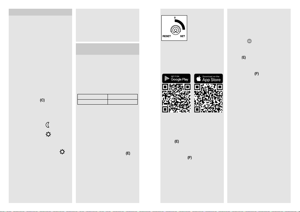
6. Fonctions
Le détecteur de mouvement fonctionne
également sans intégration dans un
réseau Z-Wave. La temporisation
est alors réglée de manière fixe sur
3minutes. Après la phase d'étalonnage
de 10 secondes, le détecteur de
mouvement est activé pour fonctionner
en détection. Il est maintenant possible
d'intégrer le détecteur de mouvement
dans le réseau Z-Wave.
Les boutons de réglage ou le réseau
Z-Wave permet(tent) d'eectuer les
réglages. Les dernières valeurs réglées
sont toujours valables peu importe si
elles ont été réglées via les boutons de
réglage ou par l'intermédiaire du réseau
Z-Wave.
Réglages eectués en usine
Réglage de la luminosité
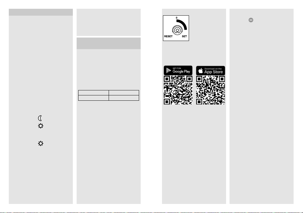
de déclenchement
Temporisation : 3 min
Réglage de la luminosité de
déclenchement (fig.5.1/C)
réglable progressivement
Bouton de réglage sur
fonctionnement nocturne, env. 2 lx
Bouton de réglage sur
fonctionnement diurne, env. 2000 lx
Remarque : pour le réglage de la
zone de détection en plein jour, il faut
mettre le bouton de réglage sur
fonctionnement diurne.
Réglage de la portée/Ajustage
Il est possible de régler la zone de
détection de façon optimale en fonction
des besoins.
Détecteur
– Possibilité d'orienter le détecteur de
180° à l'horizontale. (fig.5.2)
– Possibilité de faire basculer le détec-
teur de 90° à la verticale. (fig.5.5)
: 2000lx
=
=
=
Cache autocollant (fig. 5.3)
Le cache sert à masquer le nombre
voulu de segments de lentille et à limiter
individuellement la portée. Cela permet
d'exclure tout déclenchement intempestif ou de surveiller de manière ciblée
les zones dangereuses. (fig.5.4)
Bouton de réglage Z-Wave (E)
Bouton de réglage
pour l'inclusion et
l'exclusion ainsi que
pour la réinitialisation
de l'appareil aux
réglages eectués en
usine.
7. Intégration dans des
réseaux Z-Wave
Ce détecteur de mouvement peut fonctionner dans tous les réseaux Z-Wave
avec des appareils Z-Wave certifiés
d'autres marques. Tous les nœuds
de réseau fonctionnant sans batterie
dans le réseau assurent la fonction
d'amplificateur indépendamment du
fournisseur respectif afin d'augmenter
la fiabilité du réseau.
Inclusion Ajouter
Exclusion Supprimer
Ce mode d'emploi expliquant
l'inclusion et l'exclusion des appareils
Z-Wave Steinel a été rédigé pour le
système Smart Friends. Il peut y avoir
des diérences en cas d'utilisation
d'autres appareils Z-Wave. Vous
trouverez de plus amples informations
à ce sujet dans la description de votre
contrôleur Z-Wave. (Pour démarrer le
mode d'inclusion ou d'exclusion du
détecteur de mouvement, tournez le
bouton de réglage de l'appareil
« Set », puis remettez-le sur « 0 » dans
les 5 secondes qui suivent).
Une fois l'exclusion terminée, tous les
paramètres de configuration (durée,
sensibilité, etc.) sont conservés jusqu'à
la prochaine inclusion et le luminaire
fonctionne maintenant en mode
autonome d'où la possibilité d'utiliser
également Z-Wave pour le réglage
autonome du luminaire.
- 26 - - 27 -
sur
Ajouter le détecteur de mouvement
IS 140-2 au système Smart Friends :
1 Téléchargez l'application Smart
Friends dans la boutique des applications.
2 Activez le mode d'édition à l'écran de
visualisation des pièces.
3 Sélectionnez la pièce souhaitée
et appuyez sur le bouton
« Ajouter appareil ».
4 Tournez le bouton de réglage de l'ap-
pareil
sur « Set », puis remettez-le
sur « 0 » dans les 5secondes qui
suivent afin de mettre le détecteur de
mouvement dans le mode inclusion.
La LED d'état
le détecteur de mouvement est dans
ce mode.
5 Vous recevez un message de
confirmation dans l'application une
fois l'inclusion réussie.
allumée signale que
Supprimer le détecteur de mouvement IS 140-2 du système Smart
Friends :
1 Activez le mode d'édition à l'écran de
visualisation des pièces.
2 Sélectionnez l'appareil dans la pièce
souhaitée et appuyez sur le bouton
«Delete»
«Supprimer» et suivez les
instructions données par l'application.
3 Tournez le bouton de réglage de l'ap-
pareil
sur « 0 » dans les 5secondes qui
suivent afin de mettre le détecteur de
mouvement dans le mode exclusion.
La LED d'état
le détecteur de mouvement est dans
ce mode.
4 Vous recevez un message de
confirmation dans l'application une
fois l'exclusion réussie.
Régler le détecteur de mouvement
IS 140-2 avec l'application
– Une fois l'apprentissage terminé, un
– Les valeurs de réglage suivantes
a) Réglage de la luminosité de
b) Temporisation = 3 min de
– Il est possible de régler à la seconde
. Appuyez sur
sur « Set », puis remettez-le
rouge signale que
scénario Marche/Arrêt est automatiquement créé dans l'application.
sont alors automatiquement
mémorisées :
déclenchement = réglage du
bouton de réglage
temporisation de l'extinction
ou au lux près la luminosité de
déclenchement et la temporisation
dans le menu « Scénario ».
Page 15
3
5
ANS
DE GARANTIE
ANS
FABRICANT
Remettre le détecteur de
mouvement IS 140-2 aux réglages
eectués en usine :
Veuillez uniquement procéder comme
suit si le régulateur principal du réseau
manque ou ne fonctionne pas pour
toute autre raison.
1 Tournez le bouton de réglage de l'ap-
pareil
sur « Set », puis remettez-le
sur « Reset » (Réinitialisation) dans les
5 secondes qui suivent.
2 La réinitialisation par défaut est
signalée par la LED d'état
3 L'appareil n'est maintenant plus
inclus dans le système Z-Wave et a
été réinitialisé aux réglages eectués
en usine.
Remarque : vous pouvez télécharger
la version actuelle du micrologiciel pour
le détecteur de mouvement sur le site
Internet z-wave.steinel.de.
8. Utilisation/Entretien
Les conditions atmosphériques
peuvent influencer le fonctionnement
du détecteur de mouvement car les
fortes rafales de vent, la neige, la pluie
ou la grêle peuvent provoquer un déclenchement intempestif, les variations
brutales de température ne pouvant
pas être diérenciées des sources de
chaleur. Si la lentille de détection se
salit, la nettoyer avec un chion humide
(ne pas utiliser de détergent).
9. Déclaration de
conformité CE
Le soussigné, STEINEL Vertrieb GmbH,
déclare que l'équipement radioélectrique du type IS140-2Z-Wave est
conforme à la directive 2014/53/UE.
Le texte complet de la déclaration UE
.
de conformité est disponible à l'adresse
internet suivante: www.steinel.de
10. Recyclage
Les appareils électriques, les accessoires et les emballages doivent être
soumis à un recyclage respectueux de
l’environnement.
Ne jetez pas les appareils
électriques avec les ordures
ménagères!
Uniquement pour les pays de l’UE:
conformément à la directive
européenne en vigueur relative aux
appareils électriques et électroniques
usagés et à son application dans le
droit national, les appareils électriques
qui ne fonctionnent plus doivent être
collectés séparément des ordures
ménagères et doivent faire l’objet d’un
recyclage écologique.
11. Garantie du fabricant
Ce produit STEINEL a été fabriqué avec
le plus grand soin. Son fonctionnement et sa sécurité ont été contrôlés
suivant des procédures fiables et il
a été soumis à un contrôle final par
sondage. STEINEL garantit un état et un
fonctionnement irréprochables. La durée
de garantie est de 36 mois et débute au
jour de la vente au consommateur. Nous
remédions aux défauts provenant d'un
vice de matière ou de construction. La
garantie sera assurée à notre discrétion
par réparation ou échange des pièces
défectueuses. La garantie ne s'applique
ni aux pièces d'usure, ni aux dommages
et défauts dus à une utilisation ou
maintenance incorrecte.
Les dommages consécutifs causés
à d’autres objets sont exclus de la
garantie.
La garantie ne s'applique que si
l’appareil non démonté est retourné à
la station de service après-vente la plus
proche, dans un emballage adéquat,
accompagné d'une brève description
du défaut et d'un ticket de caisse ou
d'une facture portant la date d'achat et
le cachet du vendeur.
Service après-vente :
Le service après-vente de notre usine
eectue également les réparations non
couvertes par la garantie ou survenant
après l'expiration de celle-ci. Veuillez
envoyer le produit correctement emballé
à la station de service après-vente la
plus proche.
DE GARANTIE
FABRICANT
12. Caractéristiques techniques
Dimensions H × l × P 70 × 86 × 95 mm
Raccordement au secteur 230 à 240 V, 50 Hz
Puissance
Lampe à incandescence / halogène
Tubes fluorescents ballasts électroniques
Tubes fluorescents non compensés
Tubes fluorescents compensés en série
Tubes fluorescents compensés en parallèle
Lampes halogènes basse tension
Technique de détection détecteur infrarouge passif
Angle de détection 140° avec détect. au ras du mur
Portée max. 14 m (stabilisée en tempéra-
Temporisation 3 min (réglage eectué en usine) /
Réglage de la luminosité de déclenchement de 2 à 2000 lx en appuyant sur
Indice de protection IP 54
Intervalle de température de - 20 °C à + 50 °C
Portée radio de Z-Wave env. 100 m (champ libre)
Bande de radiofréquences 868 MHz
Puissance d'émission ≤ 2,5 mW
LED < 2 W
2 W < LED < 8 W
LED > 8 W
Charge capacitive
1000 W
430 W
500 VA
500 VA
500 VA
1000 VA
16 W
64 W
64 W
132 μF
ture) via les boutons de réglage
de 1s à 15min via l'application
les boutons de réglage et avec
l'application
- 29 -- 28 -
Page 16
13. Dysfonctionnements
Problème Cause Solution
N'est pas sous tension
L'appareil ne s'allume
pas
L'appareil ne s'éteint pas
L'appareil s'allume et
s'éteint continuellement
Fusible défectueux,
appareil hors circuit
Court-circuit
Pendant la journée, le
réglage de la luminosité
de déclenchement est
en position nocturne
Ampoule à incandes-
cence défectueuse
Interrupteur en position
ARRÊT
Fusible défectueux
Réglage incorrect de la
zone de détection
Mouvement continu
dans la zone de
détection
Le luminaire raccordé se
trouve dans la zone de
détection et se rallume
sous l'eet des variations de température
Marche forcée com-
mandée au niveau de
l'interrupteur en série de
l'habitation
Le luminaire raccordé
se trouve dans la zone
de détection
Des animaux se
déplacent dans la
zone de détection
Changer le fusible
défectueux, mettre
l'interrupteur en circuit,
vérifier le câble à l'aide
d'un testeur de tension
Vérifier le branchement
Régler à nouveau
Changer l'ampoule à
incandescence
Mettre en circuit
Changer le fusible,
éventuellement vérifier le
branchement
Régler à nouveau
Contrôler la zone de
détection, éventuellement la régler à nouveau ou la masquer
Contrôler la zone de
détection
Mettre l'interrupteur en
série sur commande
automatique
Contrôler la zone de
détection
Contrôler la zone de
détection. Orienter le
détecteur plus vers le
haut ou le masquer ;
modifier la zone ou la
masquer
Problème Cause Solution
Allumage intempestif
Il n'est pas possible
d'ajouter l'appareil au
système (et il n'a pas
encore été ajouté)
Il n'est pas possible
d'ajouter l'appareil au
système
La LED d'état
toutes les 5 secondes
pendant 1 seconde
La LED d'état
rapidement et en
permanence
Le vent agite des arbres
et des arbustes dans la
zone de détection
Détection de voitures
passant sur la chaussée
Variations subites de
température dues aux
intempéries (vent, pluie,
neige) ou à des courants
d'air provenant de ventilateurs ou de fenêtres
ouvertes
La distance entre
l'appareil et le contrôleur
Z-Wave est trop grande
Il existe déjà Retirer l'appareil du
clignote
Pas de contact radio
avec le Smart Friends
Box ou avec d'autres
contrôleurs Z-Wave
clignote
Erreur critique Débrancher pendant un
Contrôler la zone de
détection
Contrôler la zone de
détection
Modifier la zone, monter
l'appareil à un autre
endroit
Réduire la distance entre
l'appareil et le contrôleur
Z-Wave
Intégration d'un répéteur
Z-Wave
réseau existant
Exécuter une réinitialisa-
tion par défaut
Redémarrer le Smart
Friends Box ou le
contrôleur Z-Wave
Réduire la distance entre
l'appareil et le contrôleur
Z-Wave
Intégration d'un répéteur
Z-Wave
court instant l'appareil
du circuit électrique
- 30 - - 31 -
Page 17
NL
!
1. Over dit document
Zorgvuldig doorlezen en bewaren
a.u.b.!
– Rechten uit het auteursrecht voor-
behouden. Vermenigvuldiging, ook
van delen van deze handleiding,
is alleen met onze toestemming
geoorloofd.
– Wijzigingen in het kader van de
technische vooruitgang voorbehouden.
Toelichting van de symbolen
Waarschuwing voor gevaar!
Verwijzing naar tekstpassages
...
in het document.
2. Algemene
veiligheidsvoorschriften
Voor alle werkzaamheden aan het
apparaat dient de spanningstoevoer
te worden onderbroken!
• Bij de montage moet de aan te sluiten elektrische kabel spanningsvrij
zijn. Daarom eerst de stroom uitschakelen en op spanningsloosheid
testen met een spanningstester.
• Bij de installatie van de sensor
wordt met netspanning gewerkt. Dit
moet door een vakman en volgens
de gebruikelijke installatievoorschriften en aansluitingsvoorwaarden
worden uitgevoerd.
(bijv. DE - VDE 0100, AT - ÖVE /
ÖNORM E8001-1, CH - SEV 1000)
• Gebruik uitsluitend originele reserveonderdelen.
• Reparaties mogen uitsluitend door
een vakbedrijf worden uitgevoerd.
3. IS 140-2 Z-wave
Gebruik volgens de voorschriften
– Infrarood-bewegingsmelder voor
inbouw of opbouw, zowel binnen
als buiten
– De sensormodule kan verticaal en
horizontaal worden gedraaid
Beweging schakelt licht, alarm en
veel meer aan. Voor uw gemak en uw
veiligheid. De ingebouwde pyro-elektrische infrarooddetector registreert
de onzichtbare warmtestraling van
bewegende mensen, dieren enz. Deze
zo geregistreerde warmtestraling wordt
elektronisch omgezet en schakelt
hierdoor de aangesloten verbruiker
automatisch in. Door hindernissen,
zoals muren of ruiten, wordt geen
warmtestraling herkend, dus vindt
ook geen schakeling plaats. De
infraroodsensor is geschikt voor het
automatisch schakelen van licht. Voor
speciale inbraakalarminstallaties is
het apparaat niet geschikt, omdat de
voorgeschreven sabotagebeveiliging
hiervoor ontbreekt.
Dit apparaat kan in het Smart
Friends systeem en in ieder ander
Z-wave-netwerk worden geïntegreerd.
Z-wave is een draadloze standaard
waarmee Z-wave-apparaten worden
gekoppeld. De sensorafmetingen van
de bewegingsmelder IS 140-2 kunnen
worden gebruikt voor het draadloos
automatiseren van gebouwen.
Behalve de gecertificeerde Z-wavecontrollers wordt ook het gebruik van
de Smart Friends Box aanbevolen. Met
behulp van deze SmartHome-centrale
kunnen de Z-wave-producten van
STEINEL en de Smart Friends-producten van ABUS, Paulmann en Schellenberg met elkaar worden verbonden.
- 32 - - 33 -
Bij de levering inbegrepen (afb. 3.1)
Zwenkbereik sensor (afb. 3.2/5.2/5.5)
Productafmetingen (afb. 3.3)
Overzicht apparaat (afb. 3.4)
Sensorhuis
Wandhouder
Instelknop schemerschakelaar
Sensorunit
Z-wave-draaiknop
Status-led-lampje
Reikwijdte (afb. 4.1)
4. Elektrische installatie
• Stroomtoevoer uitschakelen
(afb.3.5)
Aansluiting van de stroomtoevoer
De stroomtoevoer bestaat uit een
3-aderige kabel:
L = fase (meestal zwart of bruin)
N = nuldraad (meestal blauw)
PE = aarde (meestal groen/geel)
In geval van twijfel moeten de leidingen
met een spanningstester worden
geïdentificeerd; vervolgens weer spanningsvrij maken. Aardedraad indien
nodig doorschakelen.
Belangrijk: verwisseling van de
aansluitingen leidt in het apparaat of in
uw zekeringenkast tot kortsluiting. In dit
geval moeten de afzonderlijke kabels
geïdentificeerd en opnieuw gemonteerd
worden. In de stroomtoevoerkabel kan
een geschikte netschakelaar voor INen UIT-schakelen worden gemonteerd.
De stroomkring moet met een veiligheidsschakelaar voor een 10 A-leiding
worden beveiligd.
Aansluitingstekening (afb. 3.5)
5. Montage
• Alle onderdelen controleren op
beschadigingen.
• Neem het product bij beschadigingen niet in gebruik.
• Kies een passende montageplaats; houd hierbij rekening met
de reikwijdte en de bewegingsregistratie (afb. 4.1). De veiligste
bewegingsregistratie heeft u als de
sensor zijdelings in de looprichting
gemonteerd resp. gericht wordt
en het zicht niet belemmerd wordt
door hindernissen (zoals bomen,
muren etc.) (afb.4.2/4.3).
Montagestappen
• Stroomtoevoer uitschakelen
• Behuizing
• Boorgaten aftekenen (afb. 4.6)
• Gaten boren en pluggen insteken
(afb. 4.7)
• Afdichtstopje plaatsen (afb.4.8)
– kabels in de muur (afb.4.9)
– kabels op de muur met afstand-
• Condenswatergat met een 5-mmboor boren (afb. 4.11)
• Aansluitkabel aansluiten
(afb.4.12/4.13)
• Behuizing op wandhouder steken
(afb. 4.14)
• Borgschroeven inschroeven
(afb. 4.15)
• Stroomtoevoer inschakelen
(afb. 4.15)
• Functie-instellingen uitvoeren
van de wandhouder
nemen (afb. 4.5)
houders (afb.4.10)
'6. Werking'
6. Werking
De bewegingsmelder werkt ook
wanneer die niet is opgenomen in een
Z-wave-netwerk. De tijdinstelling is
hierbij vast ingesteld op 3 minuten. De
Page 18
bewegingsmelder is na de inmeetfase
van 10 seconden actief voor de sensormodus. Nu kan de bewegingsmelder geïntegreerd worden in het
Z-wave-netwerk.
De instellingen kunnen m.b.v. draaiknoppen of via het Z-wave-netwerk
worden uitgevoerd. De laatst ingestelde
waarden gelden altijd, of die nu via de
draaiknoppen werden ingesteld of via
het Z-wave-netwerk.
Fabrieksinstellingen
Schemerinstelling
Tijdinstelling: 3 min.
Schemerinstelling (afb.5.1/C)
traploos instelbaar
Instelknopje op
= ca. 2 lux
Instelknopje op
ca. 2000 lux
Opmerking: bij de instelling van het
registratiebereik bij daglicht moet het
instelknopje op
worden gezet.
Reikwijdte-instelling/afstelling
Het registratiebereik kan naar wens
optimaal worden ingesteld.
Sensorunit
– Sensorunit 180° horizontaal draaien
(afb. 5.2)
– Sensorunit 90° verticaal kantelen
(afb. 5.5)
Afdeksticker (5.3)
Met de afdekfolie kunnen zoveel
lenssegmenten als gewenst worden
afgedekt en kan dus de reikwijdte
individueel worden verkleind. Foutieve
schakelingen worden uitgesloten of
risicoplaatsen worden doelgericht
bewaakt. (afb. 5.4)
: 2000lux
= schemerstand
= daglichtstand
= daglichtstand
7. Integreren in
Z-wave-netwerken
Dit product kan in alle Z-wave-netwerken met gecertificeerde Z-wave-installaties van andere producenten worden
gebruikt. Alle niet op batterijen werkende knooppunten in het netwerk werken
als versterker - onafhankelijk van de
aanbieder - om de betrouwbaarheid
van het netwerk te verhogen.
Integreren Toevoegen
Uitsluiten Verwijderen
Deze handleiding voor het integreren
en uitsluiten van Z-wave-producten
van STEINEL werd voor het Smart
Friends systeem geschreven. Bij
andere Z-wave-producten kunnen er
afwijkingen zijn. Zie voor meer details in
de beschrijving van uw Z-wave-controller. (om de modus voor het integreren
of uitsluiten van de bewegingsmelder te
starten, moet de draaiknop van het toestel
op 'Set' en binnen 5seconden
weer terug naar '0' worden gedraaid).
Na het uitsluiten blijven alle configuratieparameters (tijd, gevoeligheid, enz.)
bewaard tot de volgende integratie en
de lamp bevindt zich nu in de stand-alone-modus – daarom kan Z-wave ook
voor de stand-alone-instelling van de
lamp worden gebruikt.
Z-wave-draaiknop (E)
Draaiknop voor het
integreren en
uitsluiten evenals om
het apparaat te
resetten naar de
fabrieksinstellingen.
IS 140-2 toevoegen aan het
Smart Friends systeem:
1 Smart Friends app downloaden uit
de App Store.
2 De bewerkingsmodus activeren op
het scherm Ruimtes.
3 De gewenste ruimte selecteren en
op de knop 'Apparaat toevoegen'
drukken.
4 Draaiknop van het apparaat
'Set' draaien en binnen 5seconden
weer terug naar '0', om de spot in de
integratiemodus te zetten. Deze modus wordt door het branden van het
status-led-lampje
5 Nadat de integratie succesvol werd
uitgevoerd, komt er een bericht ter
bevestiging via de app.
IS 140-2 verwijderen uit het
Smart Friends systeem:
1 De bewerkingsmodus activeren op
het scherm Ruimtes.
2 In de gewenste ruimte het apparaat
selecteren en op de knop 'delete'
drukken. Druk op wissen en volg de
instructies van de app.
3 Draaiknop van het apparaat
'Set' draaien en binnen 5 seconden
weer terug naar '0', om de spot in
de uitsluitingsmodus te zetten. Deze
modus wordt door het branden
van het rode status-led-lampje
aangegeven.
op
aangegeven.
op
4 Nadat de uitsluiting succesvol
werd uitgevoerd, komt er een bericht
ter bevestiging via de app.
IS 140-2 met de app instellen
Na het aanleren wordt in de app
automatisch een Aan-/Uit-scène
aangemaakt.
– De volgende instellingswaarden zijn
dan automatisch opgeslagen:
a) Schemerinstelling = instelling van
de draaiknop
b) Tijdinstelling = 3min. uitschakel-
vertraging
– In het menu 'Scène' kunnen de
schemer- en tijdsinstellingen op
de lux resp. seconde nauwkeurig
worden ingesteld.
IS 140-2 resetten naar de
fabrieksinstellingen:
Voer deze stappen a.u.b. alleen maar
uit, wanneer de hoofdregelaar van
het netwerk ontbreekt of om andere
redenen niet functioneert.
1 Draaiknop van het apparaat
'Set' draaien en binnen 5 seconden
op 'Reset' zetten.
2 Een reset wordt door kort knipperen
van het status-led-lampje
geven.
3 Het apparaat is nu niet meer
opgenomen in het Z-wave-systeem
en werd naar de fabrieksinstellingen
gereset.
Opmerking: de actuele versie van
de firmware voor de lamp kunt u downloaden onder z-wave.steinel.de.
op
aange-
- 34 - - 35 -
Page 19
8. Gebruik/onderhoud
3
5
JAAR
FABRIEKS
JAAR
GARANTIE
Weersinvloeden kunnen de werking
van de bewegingsmelder beïnvloeden,
bij hevige windvlagen, sneeuw, regen
en hagel kan een foutieve schakeling
voorkomen, omdat de plotselinge
temperatuurverschillen niet van
warmtebronnen onderscheiden kunnen
worden. De registratielens kan bij vervuiling met een vochtige doek (zonder
schoonmaakmiddel) worden gereinigd.
9. EG-conformiteitsverklaring
Hierbij verklaar ik, STEINEL Vertrieb
GmbH, dat het type radioapparatuur
IS 140-2 Z-wave conform is met
Richtlijn 2014/53/EU. De volledige tekst
van de EU-conformiteitsverklaring kan
worden geraadpleegd op het volgende
internetadres: www.steinel.de
10. Verwijderen
Elektrische apparaten, toebehoren en
verpakkingen dienen milieuvriendelijk
gerecycled te worden.
Doe elektrische apparaten
niet bij het huisvuil!
Alleen voor EU-landen:
Conform de geldende Europese richtlijn
voor gebruikte elektrische en elektronische apparatuur en hun implementatie
in het nationaal recht, dienen niet
langer bruikbare elektrische apparaten
gescheiden ingezameld en milieuvriendelijk gerecycled te worden.
11. Fabrieksgarantie
Dit STEINEL-product is met grote
zorgvuldigheid gefabriceerd, getest op
goede werking en veiligheid volgens de
geldende voorschriften, en vervolgens
steekproefsgewijs gecontroleerd.
Steinel verleent garantie op de
storingvrije werking. De garantietermijn
bedraagt 36 maanden en gaat in op
de datum van aanschaf door de klant.
Wij verhelpen gebreken die berusten
op materiaal- of productiefouten. De
garantie bestaat uit reparatie of vernieuwen van de defecte onderdelen, door
ons te beoordelen. Garantie vervalt bij
schade aan onderdelen die aan slijtage
onderhevig zijn en bij schade of gebreken die door ondeskundig gebruik
of onderhoud ontstaan. Schade aan
andere voorwerpen is uitgesloten van
garantie.
De garantie wordt alleen verleend
wanneer het niet-gedemonteerde
apparaat met korte storingsbeschrijving, kassabon of rekening (koopdatum
en winkelierstempel), goed verpakt naar
het desbetreende serviceadres wordt
gestuurd.
Service
Na afloop van de garantietermijn of bij
schade die niet onder de garantie valt,
kan er ook door ons gerepareerd worden. Gelieve het product goed verpakt
naar het dichtstbijzijnde serviceadres
te sturen.
FABRIEKS
GARANTIE
12. Technische gegevens
Afmetingen h × b × d 70 × 86 × 95 mm
Netaansluiting 230 - 240 V, 50 Hz
Vermogen
Tl-lampen elektr. voorschakelapparaten
Sensortechniek passief-infrarood
Registratiehoek 140° met onderkruipbescherming
Reikwijdte max. 14 m (temperatuur gestabiliseerd)
Tijdinstelling 3 min. fabrieksinstelling /
Schemerinstelling 2-2000 lux via draaiknop en met de app
Bescherming IP 54
Temperatuurbereik - 20 °C tot + 50 °C
Draadloos bereik Z-wave ca. 100 m (vrij veld)
Draadloze frequentie 868 MHz
Zendvermogen ≤ 2,5 mW
Gloei-/halogeenlampen
Tl-lampen, ongecompenseerd
Tl-lampen, seriegecompenseerd
Tl-lampen, parallel gecompenseerd
Halogeenlampen, laag voltage
Led < 2 W
2 W < led < 8 W
Led > 8 W
Capacitieve belasting
1000 W
430 W
500 VA
500 VA
500 VA
1000 VA
16 W
64 W
64 W
132 μF
via draaiknop
1sec. tot 15min. met de app
- 37 -- 36 -
Page 20
13. Storingen
Storing Oorzaak Oplossing
Zonder spanning
Schakelt niet aan
Schakelt niet uit
Schakelt steeds
AAN/UIT
Zekering defect,
niet ingeschakeld
Kortsluiting
Bij daglicht, scheme-
rinstelling staat op
nachtstand
Gloeilamp defect
Netschakelaar UIT
Zekering defect
Registratiebereik niet
gericht ingesteld
Permanente beweging
in het registratiebereik
Geschakelde lamp
bevindt zich binnen
het registratiebereik en
schakelt opnieuw door
temperatuurverandering
Serieschakelaar
binnenshuis staat op
permanent gebruik
Geschakelde verlichting
bevindt zich binnen het
registratiebereik
Er zijn bewegende
dieren in het registratie-
bereik
Nieuwe zekering,
netschakelaar inschakelen, kabel met spanningzoeker controleren
Aansluitingen
controleren
Opnieuw instellen
Gloeilampen verwisselen
Inschakelen
Nieuwe zekering,
eventueel aansluitingen
controleren
Opnieuw instellen
Bereik controleren en
eventueel opnieuw
instellen of afdekken
Bereik controleren
Serieschakelaar instellen
op automatisch
Bereik controleren
Bereik controleren.
Sensor hoger draaien of
gericht afdekken; bereik
veranderen of afdekken
Storing Oorzaak Oplossing
Schakelt ongewenst aan
Het apparaat kan niet
worden toegevoegd
(en is nog niet toegevoegd)
Het apparaat kan niet
worden toegevoegd
Status-led-lampje
knippert om de
5seconden gedurende
1seconde
Status-led-lampje
knippert snel en
permanent
Wind beweegt bomen
en struiken binnen het
registratiebereik
Registratie van auto's op
straat
Plotselinge verandering
van temperatuur door
het weer (wind, regen,
sneeuw) of afvoerlucht
van ventilatoren, open
ramen
Te grote afstand tussen
Z-wave-controller en
apparaat
Het is reeds toegevoegd Apparaat uit bestaande
Geen draadloos contact
met de Smart Friends
Box of andere
Z-wave-controller
Kritieke fout Het apparaat kortstondig
Bereik controleren
Bereik controleren
Bereik veranderen,
andere montageplaats
kiezen
Afstand tot Z-wave-
controller verkleinen
Inbouw van een
Z-wave-repeater
netwerk verwijderen
Default Reset uitvoeren
Smart Friends Box
of Z-wave-controller
opnieuw starten
Afstand tot Z-wave-
controller verkleinen
Inbouw van een
Z-wave-repeater
van het stroomnet
scheiden
- 38 - - 39 -
Page 21
IT
!
1. Riguardo a questo
documento
Si prega di leggerlo attentamente e
di conservarlo!
– Tutelato dai diritti d'autore. La
ristampa, anche solo di estratti,
è consentita solo previa nostra
approvazione.
– Con riserva di modifiche legate al
progresso della tecnica.
Spiegazione dei simboli
Avvertimento contro pericoli
Rimando a passaggi nel
...
documento.
2. Avvertenze generali
relative alla sicurezza
Prima di eettuare qualsiasi lavoro
sull'apparecchio, togliete sempre la
corrente!
• Durante il montaggio la linea
elettrica deve essere scollegata.
Prima del lavoro, occorre pertanto
togliere la tensione e accertarne
l'assenza mediante uno strumento
di misurazione della tensione.
• L'installazione del sensore è un lavoro che richiede un intervento sulla
tensione di rete. Essa deve quindi
venire eettuata a regola d'arte
conformemente alle prescrizioni per
l'installazione e alle condizioni di
allacciamento applicate nel singolo
paese. (per es. DE - VDE 0100,
AT - ÖVE / ÖNORM E8001-1,
CH - SEV 1000)
• Utilizzare esclusivamente pezzi di
ricambio originali.
• Le riparazioni devono essere
eettuate esclusivamente da ocine
specializzate.
3. IS 140-2 Z-Wave
Utilizzo adeguato allo scopo
– Rilevatore di movimento a raggi
infrarossi per montaggio in superficie e a incasso in ambienti interni
ed esterni.
– Modulo sensore orientabile in
orizzontale e in verticale
Il movimento fa attivare la luce, l'allarme
e molte altre cose. Per il Vostro comfort
e la Vostra sicurezza. Il rilevatore a
raggi infrarossi piroelettrico incorporato
rileva la radiazione termica invisibile
emessa da corpi in movimento (uomini,
animali, ecc.). L'irraggiamento termico
in tal modo rilevato viene trasformato in energia elettrica e permette
l'accensione dell'utenza alllacciata.
Eventuali ostacoli, come muri o lastre
di vetro, impediscono il riconoscimento
della radiazione di calore e l'utilizzatore
non entra in funzione. Il sensore a
raggi infrarossi è stato studiato per la
commutazione automatica della luce.
L'apparecchio non è adatto all'applicazione in impianti di allarme speciali
(antifurto), in quanto non dispone della
sicurezza contro il sabotaggio prescritta
per tali tipi di impianto.
Questo apparecchio può essere
integrato nel sistema Smart Friends o
in qualsiasi rete Z-Wave. Z-Wave è un
sistema radio per il collegamento in rete
di apparecchi Z-Wave. Le grandezze
del sensore del rilevatore di movimento
IS 140-2 si possono utilizzare per progettare l'automazione di case ed edifici
basata sul collegamento radio.
Oltre a Z-Wave controller certificati si
consiglia di utilizzare la Smart Friends
Box. Con l'ausilio di questa centrale
- 40 - - 41 -
SmartHome si possono collegare
in rete prodotti Z-Wave di STEINEL
e i prodotti Smart Friends di ABUS,
Paulmann e Schellenberg.
Volume di fornitura (Fig. 3.1)
Area di rotazione del sensore
(Fig. 3.2 / 5.2 / 5.5)
Dimensioni dell'apparecchio (Fig. 3.3)
Panoramica degli apparecchi
(Fig. 3.4)
Involucro del sensore
Supporto per il montaggio a muro
Regolatore per la regolazione
crepuscolare
Unità sensore
Regolatore rotativo Z-Wave
LED di stato
Raggio d'azione (Fig.4.1)
4. Installazione elettrica
• Staccare l'alimentazione di corrente
(Fig. 3.5)
Collegamento della linea di
allacciamento
La linea di allacciamento alla rete
consiste in un cavo di tre fili:
L = fase (di norma nero o marrone)
N = filo neutro (di prevalenza blu)
PE = conduttore di terra (nella mag-
gior parte dei casi verde/giallo)
In caso di dubbio occorre identificare le
linee di alimentazione elettrica con un
indicatore di tensione e poi disinserire
nuovamente la tensione. In caso di necessità far passare il conduttore di terra
per collegarlo con quello nella parete.
Importante: lo scambio di collegamenti
causa un corto circuito nell'apparecchio
o nella sua valvoliera. In questo caso è
necessario identificare i singoli cavi e
rimontarli. Nel cavo di alimentazione si
può installare un interruttore adeguato
per accendere e spegnere. Il circuito
elettrico deve essere protetto con un
interruttore di potenza automatico
da 10 A.
Disegno degli allacciamenti (Fig.3.5)
5. Montaggio
• Controllare tutti i componenti per
verificare se presentano danneggiamenti.
• In caso di danni non mettere in
funzione il prodotto.
• Scegliete un luogo di montaggio
adeguato tenendo conto del raggio
d'azione e del rilevamento del movimento (Fig. 4.1). Il campo ottimale
per il rilevamento di movimenti si
raggiunge quando il sensore viene
montato lateralmente rispetto alla
direzione di movimento, senza che
sull'area da controllare ci siano
ostacoli (come p.es. alberi, mura
ecc.). (Fig.4.2 / 4.3)
Fasi di montaggio
• Staccare l'alimentazione di corrente
• Staccare l'involucro
per montaggio a muro
• Segnare i fori (Fig.4.6)
• Eettuare i fori e inserire i tasselli
(Fig.4.7)
• Inserire il tappo di tenuta (Fig.4.8)
– Conduttore incassato (Fig.4.9)
– Conduttore in superficie con
distanziatori (Fig.4.10)
• Eettuare un foro per la condensa
con una punta da 5 mm. (Fig.4.11)
• Collegare il cavo di allacciamento.
(Fig.4.12 / 4.13)
• Infilare l'involucro sul supporto per
montaggio a muro. (Fig.4.14)
• Inserire avvitando le viti di sicurezza.
(Fig.4.15)
dal supporto
. (Fig.4.5)
Page 22
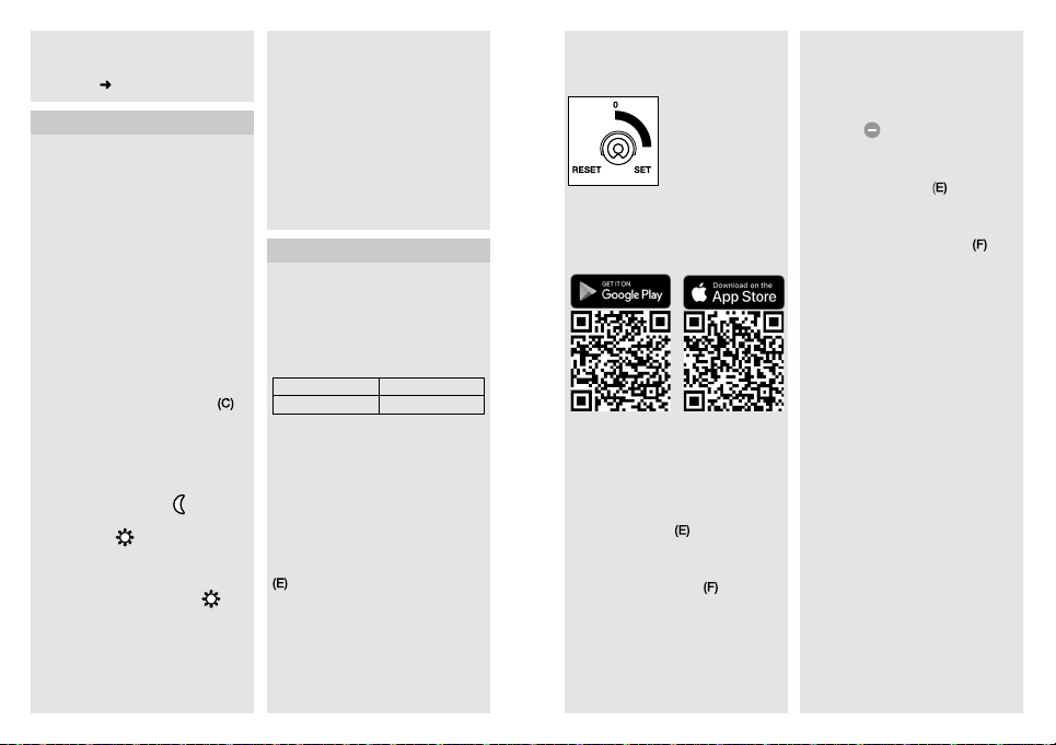
• Attivare l'alimentazione di corrente.
(Fig.4.15)
• Eettuare l'impostazione delle
funzioni
"6. Funzionamento"
6. Funzionamento
Il rilevatore di movimento funziona
anche senza integrazione in una rete
Z-Wave. La regolazione del periodo
di accensione è impostata fissa a
3minuti. Il rilevatore di movimento dopo
la fase di misurazione si spegne per 10
secondi ed è dopo di ciò attivo per il
funzionamento con sensore. Ora si può
integrare il rilevatore di movimento nella
rete Z-Wave.
Le impostazioni si possono eettuare
tramite i regolatori rotativi o attraverso la
rete Z-Wave. Valgono sempre gli ultimi
valori impostati, indipendentemente se
l'impostazione è stata eettuata tramite
i regolatori rotativi o la rete Z-Wave.
Impostazioni di fabbrica
Regolazione di luce crepuscolare
2000Lux
Regolazione del periodo di accensione:
3 min
Regolazione di luce crepuscolare
(Fig.5.1/C) in continuo
Regolatore impostato su
namento crepuscolare ca. 2 Lux
Regolatore su
namento a luce diurna ca. 2000 Lux
Avvertenza: per l'impostazione del
campo di rilevamento con luce diurna
si deve portare il regolatore su
funzionamento con luce diurna.
Impostazione del raggio d'azione/
Regolazione
Il campo di rilevamento può essere
impostato in modo ottimale secondo
delle esigenze.
= modalità di funzio-
:
= funzio-
=
Unità sensore
– Ribaltamento dell'unità sensore in
orizzontale 180°. (Fig.5.2)
– Ribaltamento dell'unità sensore in
verticale 90°. (Fig.5.5)
Calotta adesiva (Fig.5.3)
La pellicola di copertura serve a coprire
una quantità a piacere di segmenti di
lente e a ridurre così in modo individuale il raggio d'azione. Vengono esclusi
interventi a sproposito o sorvegliati in
modo mirato punti pericolosi. (Fig.5.4)
7. Integrazione in reti Z-Wave
Questo prodotto può essere utilizzato
in tutte le reti Z-Wave con dispositivi di
altri produttori certificati Z-Wave. Tutti
i nodi della rete non azionati a batteria
agiscono come amplificatori - indipendentemente dal relativo produttore - al
fine di aumentare l'adabilità della rete.
Inclusione Aggiungi
Esclusione Rimozione
Le presenti istruzioni relative all'inclusione ed esclusione di prodotti Z-Wave
di STEINEL sono state compilate per
il sistema Smart Friends. Nel caso di
altri prodotti Z-Wave vi possono essere
degli scostamenti. Ulteriori dettagli a
proposito sono indicati nella descrizione
del Vostro Z-Wave controller. (Per avviare la modalità inclusione o esclusione
del rilevatore di movimento, portare
il regolatore rotativo dell'apparecchio
su "Set" e riportarlo a "0" entro
5secondi).
Dopo l'esclusione tutti i parametri di
configurazione (tempo, sensibilità,
ecc.) vengono mantenuti e la lampada
funziona ora nella modalità stand alone
fino alla prossima inclusione - per
questo il sistema Z-Wave può essere
- 42 - - 43 -
utilizzato anche per l'impostazione
stand alone della lampada.
Regolatore rotativo Z-Wave (E)
Aggiunta dell'IS 140-2 al sistema
Smart Friends:
1 Scaricate la Smart Friends App
dall'App Store.
2 Attivate in Strumenti "Locali" la
modalità di modifica.
3 Selezionate il locale desiderato e
premete il pulsante "Aggiungi apparecchio".
4 Per portare il faro nella modalità in-
clusione, ruotate il regolatore rotativo
dell'apparecchio
"Set" e riportarlo entro 5 secondi
su "0". Il raggiungimento di questa
modalità viene segnalato dall'accensione del LED di stato
5 Se l'inclusione è riuscita viene tra-
smesso un messaggio di conferma
nella App.
Regolatore rotativo
per l'inclusione e
l'esclusione nonché
per il ripristino
dell'impostazione di
fabbrica
dell'apparecchio.
portandolo su
.
Rimozione dell'IS 140-2 dal sistema
Smart Friends:
1 Attivate in Strumenti "Locali" la
modalità di modifica.
2 Nel locale desiderato selezionate
l'apparecchio e premete il pulsante
"delete"
. Premete su "cancella" e
seguite le istruzioni nella App.
3 Per portare il faro nella modalità
esclusione, ruotate il regolatore rotativo dell'apparecchio
su "Set" e riportatelo entro 5 secondi
su "0". Il raggiungimento di questa
modalità viene segnalato dall'accensione del LED di stato rosso
4 Se l'esclusione è riuscita viene tra-
smesso un messaggio di conferma
nella App.
Impostazione dell'IS 140-2 con
la App
– Dopo l'apprendimento, nella App
viene creata automaticamente una
scena on/o.
– Sono così depositati automatica-
mente i seguenti valori d'impostazione:
a) Regolazione di luce crepuscola-
re= impostazione del regolatore
rotativo
b) Regolazione del periodo di
accensione = 3 min di ritardo
dello spegnimento)
– Nel menù "Scena" si possono
impostare le regolazioni di luce
crepuscolare e del periodo di
accensione con precisione al lux o
al secondo.
Ripristino delle impostazioni di
fabbrica dell'IS 140-2:
Si prega di eseguire queste operazioni
solo se manca il regolatore principale di
rete o quest'ultimo non è funzionante
per altre ragioni.
portandolo
.
Page 23
3
5
DI GARANZIA
ANNI
DEL PRODUTTORE
1 Portate il regolatore rotativo dell'ap-
parecchio
5secondi su "Reset".
2 Il resettaggio viene segnalato da un
breve lampeggio del LED di stato
3 Ora l'apparecchio non è più incluso
nel sistema Z-Wave ed è stato
riportato alle impostazioni di fabbrica.
Avvertenza: l'attuale versione firmware
per la lampada si può scaricare al sito
z-wave.steinel.de.
su "Set" e poi entro
8. Funzionamento/Cura
I fenomeni atmosferici possono avere
influenza sul funzionamento del rilevatore di movimento; in caso di forti folate di
vento, neve, pioggia o grandine è possibile che esso intervenga a sproposito,
in quanto non è possibile distinguere
gli improvvisi sbalzi di temperatura da
quelli dovuti alla presenza di fonti di
calore. In caso la lente di rilevamento
fosse imbrattata, pulirla con un panno
umido (senza utilizzare detergenti).
9. Dichiarazione di
conformità CE
Il fabbricante, STEINEL Vertrieb GmbH,
dichiara che il tipo di apparecchiatura
radio IS140-2Z-Wave è conforme alla
direttiva 2014/53/UE. Il testo completo
della dichiarazione di conformità UE
è disponibile al seguente indirizzo
Internet: www.steinel.de
10. Smaltimento
Apparecchi elettrici, accessori e
materiali d’imballaggio devono essere
consegnati agli appositi centri di raccolta e smaltimento.
Non gettare gli apparecchi
elettrici nei rifiuti domestici!
.
Solo per paesi UE:
Conformemente alla Direttiva Europea
vigente in materia di rifiuti di apparecchi
elettrici ed elettronici e alla sua attuazione nel diritto nazionale, gli apparecchi
elettrici ed elettronici non più idonei
all’uso devono essere separati dagli
altri rifiuti e consegnati a un centro di
riciclaggio riconosciuto.
11. Garanzia del produttore
Questo prodotto STEINEL è stato
costruito con la massima cura, con
controlli di funzionamento e del grado
di sicurezza in conformità alle norme
vigenti in materia; vengono poi eettuati collaudi con prove a campione.
STEINEL si assume la garanzia di una
fabbricazione ed un funzionamento
perfetti. La garanzia si estende a
36mesi ed inizia il giorno d'acquisto da
parte dell'utilizzatore finale. Noi eliminiamo difetti riconducibili al materiale o
alla fabbricazione; la prestazione della
garanzia consiste a nostra discrezione
nella riparazione o nella sostituzione dei
pezzi difettosi. Il diritto alla prestazione
di garanzia viene a decadere in caso di
danni a pezzi soggetti ad usura nonché
in caso di danni o difetti che sono da ricondurre ad un trattamento inadeguato
o ad una cattiva manutenzione. Sono
esclusi dal diritto di garanzia gli ulteriori
danni conseguenti che si verificano su
oggetti estranei.
La garanzia viene prestata solo se
l'apparecchio viene inviato non smontato, ben imballato e accompagnato da
una breve descrizione del difetto e dallo
scontrino o dalla fattura (in cui siano
indicati la data dell'acquisto e il timbro
del rivenditore), al centro di assistenza
competente.
Assistenza clienti: con periodo di
garanzia scaduto e nel caso di difetti
che non danno diritto a prestazioni di
garanzia, il nostro centro di assistenza
può eseguire le relative riparazioni.
Inviare il prodotto ben imballato, al più
vicino centro di assistenza.
ANNI
DI GARANZIA
DEL PRODUTTORE
12. Dati tecnici
Dimensioni A × L × P 70 × 86 × 95 mm
Allacciamento alla rete 230 – 240 V, 50 Hz
Potenza
Carico lampadine incandescenti / lampade alogene 1000 W
Lampade fluorescenti ballast elettronico 430 W
Lampade fluorescenti non compensato 500 VA
Lampade fluorescenti collegamento in serie 500 VA
Lampade fluorescenti con compensazione in parallelo 500 VA
Lampade alogene a basso voltaggio 1000 VA
LED < 2 W 16 W
2 W < LED < 8 W 64 W
LED > 8 W 64 W
Carico capacitivo 132 μF
Tecnica a sensori Infrarossi passivi
Angolo di rilevamento 140° con protezione antistrisciamento
Raggio d'azione max. 14 m (con stabilizzazione della
Regolazione del periodo di
accensione
Regolazione crepuscolare 2-2000 Lux tramite regolatore rotativo
Grado di protezione IP 54
Intervallo di temperatura da + 20 °C a + 50 °C
Raggio d'azione Z-Wave ca. 100 m (all'aperto)
Fascia di radiofrequenza 868 MHz
Potenza di trasmissione ≤ 2,5 mW
temperatura) tramite regolatore rotativo
3 min. impostazione di fabbrica /
da 1s a 15min con l'App
e con l'App
- 45 -- 44 -
Page 24
13. Disturbi di funzionamento
Guasto Causa Rimedio
Mancanza di tensione
L'apparecchio non si
accende
L'apparecchio non si
spegne
Fusibile difettoso,
apparecchio non acceso
Corto circuito
Nel funzionamento con
luce diurna l'impostazione crepuscolare è regolata sul funzionamento di
notte
Lampadina guasta
Interruttore di rete su
OFF
Fusibile guasto
Campo di rilevamento
non impostato in modo
mirato
Movimento continuo nel
campo di rilevamento
La lampada allacciata
si trova all'interno del
campo di rilevamento
e si attiva a causa del
cambiamento della
temperatura
Attraverso l'interruttore
in serie all'interno della
casa impostazione su
funzionamento continuo
Sostituire il fusibile,
accendere l'interruttore,
controllare la linea di
alimentazione con un
voltmetro
Controllare gli
allacciamenti
Eseguire una nuova
impostazione
Sostituire le lampadine
a incandescenza
Accendere l'apparecchio
Cambiare fusibile, even-
tualmente controllate
l'allacciamento
Eseguire una nuova
regolazione
Controllare il campo di
rilevamento, eseguire
eventualmente una
nuova regolazione o una
schermatura
Controllare il campo
Interruttore in serie
impostato su funzionamento automatico
Guasto Causa Rimedio
L'apparecchio si
accende e si spegne
continuamente
L'apparecchio si
accende a sproposito
Non è possibile
aggiungere l'apparecchio
(l'apparecchio non è
stato ancora aggiunto)
Non è possibile
aggiungere l'apparecchio
Il LED di stato
lampeggia ogni
5 secondi per
1 secondo
Il LED di stato
lampeggia rapidamente e
permanentemente
La lampada collegata
si trova all'interno del
campo di rilevamento
Animali in movimento
nel campo di
rilevamento
Il vento muove alberi e
cespugli nel campo di
rilevamento
Vengono rilevate
automobili sulla strada
Improvviso sbalzo di
temperatura a causa
del cambiamento delle
condizioni atmosferiche
(vento, pioggia, neve)
o presenza di aria di
scarico proveniente
da ventilatori o finestre
aperte
Distanza eccessiva tra
controller Z-Wave e
apparecchio
È già stato aggiunto Rimuovere l'apparecchio
Nessun contatto radio
con la Smart Friends Box
o altri controller Z-Wave
Errore critico Staccare per breve
Controllare il campo
Controllare il campo.
Orientare il sensore
più in alto o coprirlo in
modo mirato, spostare
o coprire il campo di
rilevamento
Controllare il campo
Controllare il campo
Modificare il campo
o spostate il luogo di
montaggio
Ridurre la distanza dal
controller Z-Wave
Montaggio di un
ripetitore Z-Wave
dalla rete esistente
Eseguire il default reset
Riavviare la Smart
Friends Box o il controller
Z-Wave
Ridurre la distanza dal
controller Z-Wave
Montare un ripetitore
Z-Wave
tempo l'apparecchio
dalla tensione di rete
- 46 - - 47 -
Page 25

Advanced Configuration
For more detailed information, please download the professional instructions from
z-wave.steinel.de.
A. Description of device endpoints:
The functionality of the device is divided to endpoints by their using.
0 = ROOT
To root summarizes whole device function, to root endpoint is mapped all
functionality from the endpoint 1 and most of the endpoints 2 and 3.
Device type = Sensor - Notification
Supported Command Classes:
COMMAND_CLASS_ZWAVEPLUS_INFO ( v2 )
COMMAND_CLASS_VERSION ( v2)
COMMAND_CLASS_FIRMWARE_UPDATE_MD ( v3 )
COMMAND_CLASS_MANUFACTURER_SPECIFIC ( v2 )
COMMAND_CLASS_MULTI_CHANNEL ( v4 )
COMMAND_CLASS_DEVICE_RESET_LOCALLY ( v1 )
COMMAND_CLASS_CONFIGURATION ( v1 )
COMMAND_CLASS_POWERLEVEL ( v1 )
COMMAND_CLASS_NODE_NAMING ( v1 )
COMMAND_CLASS_NOTIFICATION ( v4 )
COMMAND_CLASS_ASSOCIATION ( v2 )
COMMAND_CLASS_MULTI_CHANNEL_ASSOCIATION ( v3 )
COMMAND_CLASS_ASSOCIATION_GRP_INFO ( v1 )
COMMAND_CLASS_SENSOR_MULTILEVEL ( v4 )
COMMAND_CLASS_SWITCH_BINARY ( v1 )
COMMAND_CLASS_SWITCH_ALL ( v1)
COMMAND_CLASS_APPLICATION_STATUS ( v1 )
Controlled Command Classes:
COMMAND_CLASS_BASIC ( v1 )
Special meaning of BASIC CC:
BASIC CC can activate/temporary deactivate internal motion sensor using for
evaluating the behaviour of the lamp and groups 2 and 3. Events are, however,
still transmitted to the Lifeline, and the device can be controlled via remote motion
sensors. Or can be used for endpoint 3 state (please also follow the configuration
parameter 16).
For parameter 16 = 0 or 255:
Basic Set: mapped to Binary Switch Set of relay endpoint
Basic Get: mapped to Binary Switch Get of relay endpoint
Basic Report: mapped to Binary Switch Report of relay endpoint
For parameter 16 = 1-204:
Basic Set: active (0xFF) /inactive (0x00) sensor function
Basic Get: request sensor status
Basic Report: advertise sensor status
- 48 - - 49 -
1 = MOTION SENSOR
To endpoint 1 is mapped motion sensor ( PIR ) functionality.
Device type = Sensor - Notification
Supported Command Classes:
COMMAND_CLASS_ZWAVEPLUS_INFO ( v2 )
COMMAND_CLASS_BASIC ( v1 )
COMMAND_CLASS_ASSOCIATION ( v2 )
COMMAND_CLASS_NOTIFICATION ( v4 )
COMMAND_CLASS_MULTI_CHANNEL_ASSOCIATION ( v3 )
COMMAND_CLASS_ASSOCIATION_GRP_INFO ( v1 )
Controlled Command Classes:
COMMAND_CLASS_BASIC ( v1 )
Special meaning of BASIC CC:
BASIC CC can activate/temporary deactivate internal motion sensor using for
evaluating the behaviour of the lamp and groups 2 and 3. Events are, however,
still transmitted to the Lifeline, and the device can be controlled via remote motion
sensors (please also follow the configuration parameter 16).
Basic Set: active ( 0xFF ) /inactive ( 0x00 ) sensor function
Basic Get: get sensor activity
Basic Report: sensor activity status
2 = AMBIENT LIGHT SENSOR
To endpoint 2 is mapped ambient light sensor functionality.
Device type = Sensor - Multilevel
Supported Command Classes:
COMMAND_CLASS_ZWAVEPLUS_INFO ( v2 )
COMMAND_CLASS_SENSOR_MULTILEVEL ( v4 )
COMMAND_CLASS_ ASSOCIATION (v2)
COMMAND_CLASS_MULTI_CHANNEL_ASSOCIATION ( v3 )
COMMAND_CLASS_ASSOCIATION_GRP_INFO ( v1 )
Controlled Command Classes:
No
3 = RELAY
To endpoint 3 is mapped basic relay functionality.
Device type = On/O Power Switch
Supported Command Classes:
COMMAND_CLASS_ ZWAVEPLUS_INFO (v2)
COMMAND_CLASS_BASIC (v1)
COMMAND_CLASS_ ASSOCIATION (v2)
COMMAND_CLASS_MULTI_CHANNEL_ASSOCIATION (v3)
COMMAND_CLASS_ ASSOCIATION_GRP_INFO (v1)
COMMAND_CLASS_SWITCH_BINARY (v1)
COMMAND_CLASS_SWITCH_ALL (v1)
C OM MAND_ CL ASS _AP PL ICATIO N_S TATUS (v1)
Controlled Command Classes:
No
Page 26

B. Description of association groups:
0 = ROOT DEVICE
Group 1 – "Lifeline" – only 1 node
Lifeline messages
- Device Reset Locally
- Notifications:
0x09 ( System ) – Hardware failure with manufacturer proprietary code ( 0x03 )
0x09 ( System ) – Software failure with manufacturer proprietar y code ( 0x04 )
0x07 ( Home security ) – Motion Begin event ( 0x08 )
0x07 ( Home security ) – Motion End event ( 0x00, 0x08 )
- Binar y Switch Repor t – lamp state
- Multilevel Sensor Report – value of internal ambient light sensor
Motion Begin and Motion End events are sent along with frames to group 3.
If multichannel association is created the events are sent from motion sensor
endpoint.
Switch Report is sent immediately upon a change of status along with frames
to group 2. If multichannel association is created the events are sent from relay
endpoint.
Multilevel Sensor Report is sent a maximum of once per 1 minute (if the value
has changed by least by 3%) and a minimum of once per 15 minutes (if the value has not changed). If the ambient light value is old (cannot measure because
of permanent light), the value is not transmitted via lifeline. Multilevel Sensor
Repor t can be also added to some other events to send in bulk. If multichannel
association is created the events are sent from light sensor endpoint.
All notifications to lifeline are sent as sensor states regardless of sensor settings
and states as SLAVE_MODE, LOCAL_DISABLED and MOTION _ENABLE.
Group 2 – "On/O control" – max 16 nodes
Group 2 is used for directly controlling Z-Wave devices via BASIC SET commands through the evaluation of movement and light as with internal use (so
that all of these devices work together). This is intended for use especially with
third-party devices that do not implement reactions for motion events. BASIC_SET and similar Z-Wave commands are not retransmitted intentionally to
slaves and must be sent to slave devices via the controlling device simultaneously. Only for use in master-slave system, multidevice control is not possible.
Group 2 is evaluated and frames are transmitted there also in SLAVE_MODE,
regardless of LOCAL_DISABLED state and when MOTION_ ENABLE is o (not
using internal motion sensor just reacts for remote motion events then).
If multichannel association is created the events are send from motion sensor
endpoint.
Group 3 – "Notification Report" – max 16 nodes
Group 3 sends MOTION_BEGIN and MOTION_END frames.
MOTION_BEGIN frame = Notification 0x07 ( Home security )– Motion detection
withou t loc ation ( 0 x08 )
MOTION_END frame = Notification 0x07 ( Home security )– After first motion
detection MOTION_BEGIN is sent. If continual movement is detected
MOTION_BEGIN is sent every 1minute repeatedly. When motion ends,
MOTION_END is sent 5 seconds af ter the last motion detection.
Notification to group 3 is sent only when NIGHT_MODE = ON and MOTION_
ENABLE = ON, regardless of LOCAL_ DISABLE state.
All devices in a group should have the same TIME settings in order that they
switch o at the same time.
If multichannel association is created the events are send from motion sensor
endpoint.
Group 4 – "Ambient light" – max 16 nodes
Ambient Light via group 4 is intended to substitute locally measured LUX
values in target devices – so that the network can have one source of ambient light value. The frame rate is a value being sent a ma ximum of once per
2.5minutes, and a minimum of once per 15 minutes.
When device already uses remote Ambient light value, then this value is also
retransmitted to group 4.
All devices in such a group should have the same LIGHT ( threshold ) settings
in order that night mode is detected at the same time.
If multichannel association is created the events are send from light sensor
endpoint.
1 = MOTION SENSOR
The lifeline messages are sent via Root lifeline if not used multichannel
association.
Group 2 – its mirror of group 2 of root
Group 3 – its mirror of group 3 of root
2 = AMBIENT LIGHT SENSOR
The lifeline messages are sent via Root lifeline if not used multichannel
association.
Group 2 – its mirror of group 4 of root
3 = RELAY
The lifeline messages are sent via Root lifeline if not used multichannel
association.
- 50 - - 51 -
Page 27
C. Configuration description:
Time [ s ]:
Parameter Number Size Range Default
Duration of light after motion detection.
Light threshold [lx]:
0 – run Learn ambient light sequence.
2000 - is used as daylight ( always night mode ).
Value can be controlled via potentiometer – potentiometer value is used as the
default value and any potentiometer movement rewrites the current setting.
Motion Sensor (PIR) Sensitivity [%]:
Value can be controlled via potentiometer – potentiometer value is used as the
default value and any potentiometer movement rewrites the current setting.
Brightness measuring interval [ minutes ]:
6 ( BRIGHTNES MEAS INTERVAL ) 1 5-120, 0 0
Interval for ambient light measuring when lamp is on ( lamp switches o shortly
and measures ). 0 = function is o.
Use External Ambient Light Value:
When GLOBAL_LIGHT mode is ON – device overrides its own light sensor
values and uses Light report values from any Z-Wave light sensor instead –
this has to be configured appropriately to send light automatically.
If the last remote light level value is older than 30 minutes, the internal light
value is used again until the next external value is received.
1 ( TIME ) 2 5-900 180
Parameter Number Size Range Default
2 ( LIGHT ) 2 2-2000, 0 2000/poti state
Parameter Number Size Range Default
5 ( SENSITIVITY ) 1 2-100 100
Parameter Number Size Range Default
Parameter Number Size Range Default
8 ( GLOBAL_LIGHT ) 1 0/1 1
Disable local control:
Parameter Number Size Range Default
9 ( SLAVE_MODE ) 1 0-4 2
Bit Field:
bit 7 6 5 4 3 2 1 0
function - - - - -
"Stupid" mode ( bit 2 = 1 ):
- has higher priority then slave mode.
- lamp is permanently on ( usefull for simple power wall switch controlling ).
Slave mode ( bit 0 = 1 ):
- only if included in Z-Wave network
- usefull for controlling via third-party sensor
- lamp is directly controlled via Z-Wave, internal sensors are not used for
controlling it.
Central unit checking ( bit 1 = 1 ):
( usefull especialy for controlling via gateway )
When Slave bit is 0:
- lamp signalises fail of lifeline connection ( if this bit is zero fail of lifeline
connection is not signalised )
When slave bit is 1:
- lamp checks presence of Z-Wave device in lifeline group ( gateway ). If it is
not present for 2minutes ( testing repeatedly every 30seconds ) device
switches to normal mode in the same way as after the end of local disabled
mode ( O N_BE HAVIOUR )
- The device checks every 1minute for recovery of Lifeline connection.
- if no lifeline specified - it works in normal mode
Be careful with this option, lamp stops using it’s own motion sensor in
Slave and Stupid mode.
O behavior ( timeout ):
Parameter Number Size Range Default
10 ( OFF_BEHAVIOUR ) 2 0 – 209,255 10
Behaviour after BASIC OFF ( and similar commands ).
"Stupid"
mode
Central unit
checking in
slave mode
Slave
mode
- 52 - - 53 -
Page 28
If a transition ( even with zero change ) with a non-default duration is to be processed, the transition cannot be interrupted by any motion event in any case.
0
1 - 209
210 - 254 Reserved
255
On behaviour ( timeout ):
Behaviour after BASIC ON ( and similar commands ).
If a transition ( even with zero change ) with a non-default duration is to be processed, the transition cannot be interrupted by any motion event in any case.
0
1 -209
210 - 254 Reserve
255
Lamp is switched o and remains so until any new motion event
( local or remote ) is received.
Lamp is switched o and remains so until after a specified timeout
once a new motion event ( local or remote ) is received.
Timeout:
1..100 – 1 second ( 1 ) to 100 seconds ( 100 ) in 1-second resolution
101..200 – 1 minute ( 101 ) to 100 minutes ( 200 ) 1-minute resolution
201..209 – 1 hour ( 201 ) to 9 hours ( 209 ) in 1-hour resolution
Lamp is switched o for TIME ( cfg 1 ). It does not wait for a
motion event and works normally via current motion evaluation.
Parameter Number Size Range Default
11 ( ON_BEHAVIOUR ) 2 0 – 209, 255 255
Lamp is switched on and remains so until any new motion event
( local or remote ) is received. It then works normally via current motion
evaluation.
Notice – during the day, this mode cannot be ended remotely due to
motion events not being transmitted – only via local motion sensor if
enabled.
Lamp is switched on and remains so until after a specified timeout
once a new motion event ( local or remote ) is received. It then works
normally via current motion evaluation.
Timeout:
1..100 – 1 second ( 1 ) to 100 seconds ( 100 ) in 1-second resolution
101..200 – 1 minute ( 101 ) to 100 minutes ( 200 ) in 1-minute resolution
201..209 – 1 hour ( 201 ) to 9 hours ( 209 ) in 1-hour resolution
Notice – during the day, this mode cannot be ended remotely due to
motion events not being transmitted – only via local motion sensor if
enabled.
Lamp is switched on for TIME ( cfg 1 ). It does not wait for a motion
event and works normally via current motion evaluation.
- 54 - - 55 -
On behavior time over ( timeout ):
Parameter Number Size Range Default
12 ( ON_TIME_OVER ) 2 0 – 209, 255 204
Time limit to stop waiting for motion after timeout of ON_BEHAVIOUR or
OFF_ON_BEHAVIOUR ( 0-209 ) to prevent staying ON forever when is no motion.
0 Stop waiting just after timeout.
1 -209
210 - 254 Reserve
255 Never stop waiting before motion.
Sequence On-O behavior ( timeout ):
Behaviour after after a rapid sequence of BASIC ON and BASIC OFF
commands.
The intention is to use a much longer timeout value than the time after a single
ON command which should then be followed by a short timeout value.
The behaviour is the same as for parameter 10 ( OFF_LOCAL_DISABLE ) except:
255 – device ignores ON - OFF sequence and uses OFF behavior
Sequence O-On behavior ( timeout ):
Behaviour after after a rapid sequence of BASIC OFF and BASIC ON
commands.
The intention is to use a much longer timeout value than the time after a single
OFF command which should then be followed by a short timeout value.
The behaviour is the same as for parameter 11 ( ON_LOCAL_DISABLE ) butexcept: 255 – device ignores OFF - ON sequence and uses ON behaviour.
1..100 – 1 second ( 1 ) to 100 seconds ( 100 ) in 1-second resolution
101..200 – 1 minute ( 101 ) to 100 minutes ( 200 ) in 1-minute resolution
201..209 – 1 hour ( 201 ) to 9 hours ( 209 ) in 1-hour resolution
Parameter Number Size Range Default
13 ( ON_OFF_BEHAVIOR ) 2 0 – 209, 255 204
Parameter Number Size Range Default
14 ( OFF_ON_BEHAVIOUR ) 2 0 – 209, 255 204
Page 29
Sequency timing:
Parameter Number Size Range Default
15 ( SEQUENCY_TIME ) 1 10 – 50 10
Time in [100 miliseconds] of ma ximum delay between BASIC ON and BASIC
OFF (and vice versa) to relay endpoint to consider this as a sequence. It is
typically 1 second, but can be exceptionally longer due to retransmissions and
overload – in this case, a longer interval can be allowed (up to 5 seconds).
Motion O behaviour (timeout):
Parameter Number Size Range Default
16 (MOTION_DISABLE) 2 0 – 209, 255 0
Motion disable timeout after BASIC SET to motion endpoint when the internal
motion sensor is not used for evaluating the behaviour of the relay and groups
2 and 3. Events are, however, still transmitted to the Lifeline, and the relay can
be controlled via remote motion sensors.
0
1 -209
210-254 Reserve
255
BASIC SET to Motion sensor endpoint ignored, BASIC to root is
mapped to relay endpoint, motion sensor still enabled
Internal motion sensor is disabled for specified timeout after BASIC
SET 0x00 to Mootion sensor endpoint. BASIC to root is mapped to
Motion sensor endpoint.
Timeout:
1..100 – 1 second (1) to 100 seconds (100) in 1-second resolution
101..200 – 1 minute (101) to 100 minutes (200) in 1-minute resolution
201..209 – 1 hour (201) to 9 hours (209) in 1-hour resolution
BASIC SET to Motion sensor endpoint ignored, BASIC to root is
mapped to relay endpoint, motion sensor still disabled
- 56 -
 Loading...