

Steinbach Waterpower 8500, BP-35WS-B, Speedheat Waterpower 5000, Speedheat Waterpower 8500, BP-50WS-B User Manual
...Page 1
IRUWRGD\µVOLIHVW\OH
User manual
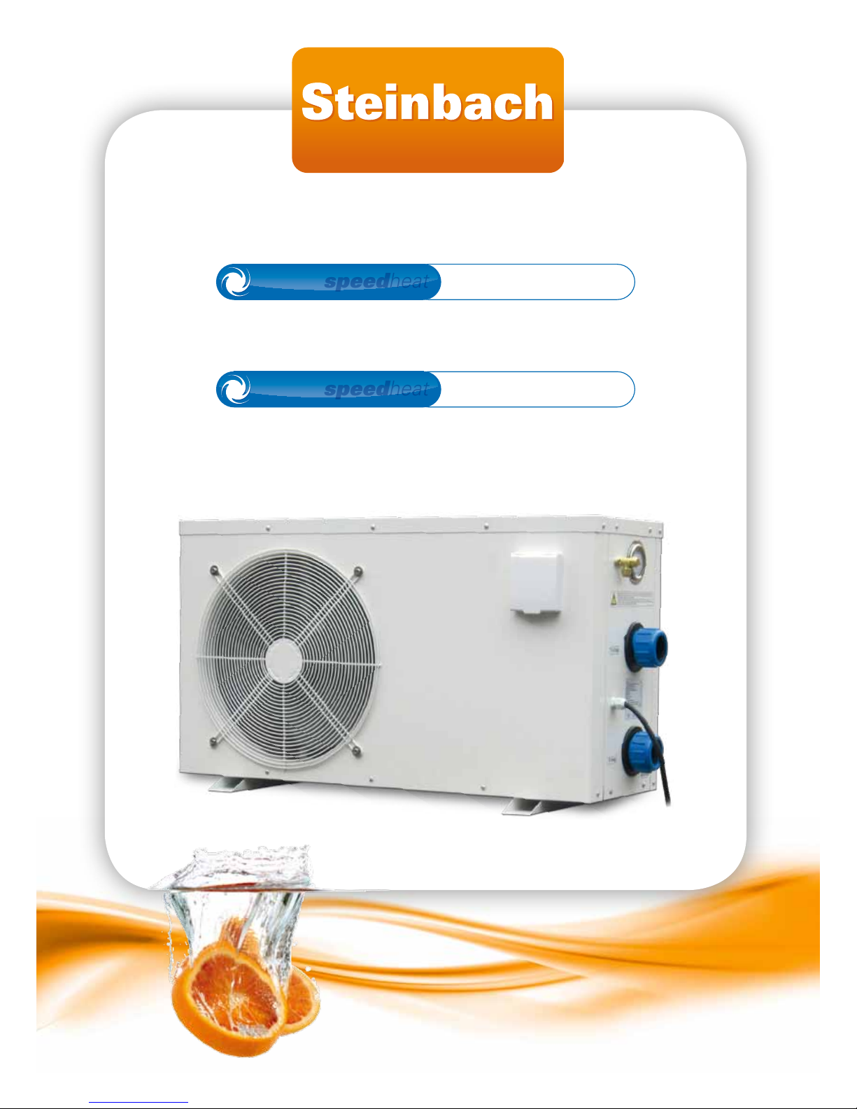
speedheat
Waterpower 5000
speedheat
Art.Nr.: 00-49200 / BP-50HS-A
speedheat
Waterpower 8500
speedheat
Art.Nr.: 00-49205 / BP-85HS-A
Page 2

Page 3

Speedheat Waterpower page 3 of 44
IRUWRGD\µVOLIHVW\OH
Contents.
1.
General warnings and information for the addressee. .........................................................5
1.1. Service Processing ..................................................................................................................5
1.2. Warranty...............................................................................................................................6
1.2.1. General conditions. .....................................................................................................6
1.2.2. Special conditions........................................................................................................6
1.2.3. Restrictions. .................................................................................................................6
1.3. Symbol key...........................................................................................................................7
1.4. Safety regulations for heated pools.....................................................................................7
1.5. Energy savings. ...................................................................................................................7
1.6. General information. ............................................................................................................7
1.7. Definitions. ...........................................................................................................................8
2. Product presentation. ...............................................................................................................8
2.1. Product scope. .....................................................................................................................8
2.2. Composition. ........................................................................................................................9
3. Technical specifications.........................................................................................................10
4. Installation................................................................................................................................11
4.1. Inspection...........................................................................................................................11
4.2. Handling. ............................................................................................................................ 11
4.3. Positioning..........................................................................................................................11
4.3.1. Support and its location.............................................................................................11
4.3.2. Necessary clearance. ................................................................................................12
4.3.3. Noise wave echo. ......................................................................................................12
4.4. Disposal. ............................................................................................................................12
4.4.1. General instructions. .................................................................................................12
4.4.2. Heat pump decommissioning....................................................................................12
4.4.3. Electric/electronic waste disposal. ............................................................................13
4.5. Hydraulic connections........................................................................................................13
4.5.1. Warnings.................................................................................................................... 13
4.5.2. Installation hydraulic layout. ......................................................................................13
4.6. Electrical connections. .......................................................................................................14
4.7. Commissioning, preliminary checks. .................................................................................15
4.7.1. Commissioning, precautions. ....................................................................................15
4.7.2. First start-up, preliminary checks. .............................................................................15
5. Operations and use. ................................................................................................................16
5.1. Introduction. .......................................................................................................................16
5.2. Control panel use...............................................................................................................16
5.2.1. Turning on the heat pump. ........................................................................................16
5.2.2. Standby...................................................................................................................... 16
5.2.3. Turning off the heat pump. ........................................................................................16
5.2.4. Starting the heat pump. ............................................................................................. 17
5.2.5. Operating mode selection. ........................................................................................17
5.2.6. Set temperature regulation........................................................................................ 17
5.2.7. Minimum working temperature and restart temperature. .........................................17
5.2.8. Automatic start settings. ............................................................................................18
5.2.9. Automatic standby settings. ......................................................................................18
5.2.10. Manual defrost. .......................................................................................................... 19
5.2.11. Key lock. ....................................................................................................................19
5.2.12. Sensor temperature display. .....................................................................................19
5.3. Manometer use. ................................................................................................................. 20
6. Control and safety devices. ...................................................................................................21
6.1. Control devices. ................................................................................................................. 21
6.1.1. Ambient and pool temperature sensors. ...................................................................21
6.1.2. Flow sensor. ..............................................................................................................21
6.2. Safety devices....................................................................................................................21
Page 4

Speedheat Waterpower page 4 of 44
IRUWRGD\µVOLIHVW\OH
6.2.1.
Compressor and plate heat exchanger temperature sensors. .................................21
6.2.2. High pressure sensor. ...............................................................................................21
6.2.3. Low pressure sensor. ................................................................................................ 22
7. Routine, scheduled and extraordinary maintenance..........................................................23
7.1. User controls......................................................................................................................23
7.2. Specialised technician controls. ........................................................................................23
7.3. Winter protection................................................................................................................23
7.4. Spring commissioning........................................................................................................ 23
7.5. Troubleshooting. ................................................................................................................ 23
8. Spare parts. ..............................................................................................................................27
Page 5
Speedheat Waterpower page 5 of 44
IRUWRGD\µVOLIHVW\OH
1. General warnings and information for the addressee.
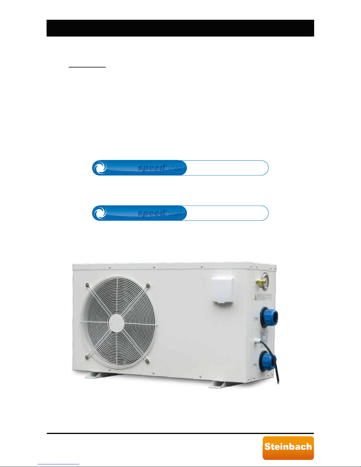
speedheat
Waterpower 5000
speedheat
Art.Nr.: 00-49200 / BP-50HS-A
speedheat
Waterpower 8500
speedheat
Art.Nr.: 00-49205 / BP-85HS-A
1.1. Service Processing
For technical information, missing parts or in the case of a complaint, please contact our customer service:
Important note: On the pump label of your heat pump is a production number shown, please provide
this number in the case of a complaint.
Steinbach VertriebsgmbH, Aistingerstrasse 2, 4311 Schwertberg, AUSTRIA
Tel. Austria: (0820) 200 100 111 (0,145€ per minute from all networks)
Tel. Germany: (0180) 5 405 100 111 (0,14€ per minute from landline, mobile radio max. 0,42€ per minute)
e-mail: [email protected], www.steinbach.at
Page 6

Speedheat Waterpower page 6 of 44
IRUWRGD\µVOLIHVW\OH
1.2. Warranty.
1.2.1. General conditions.
i. In accordance with these provisions, the dealer guarantees that the Product under
this warranty (“the Product”) does not have any conformity defect upon delivery.
ii. The Product Warranty Period is two (2) years, effective upon delivery to the
purchaser.
iii. In the event of Product conformity defects and the purchaser informs the dealer
during the Warranty period, the dealer must repair or replace the Product at
his/her own expense and at the site deemed most suitable, unless this is
impossible or out of proportion.
iv. Should the Product be irreparable or irreplaceable, the purchase may request a
proportionate price reduction or, if the conformity defect is sufficiently important,
the termination of the sales contract.
v. Parts replaced or repaired under this warranty do not extend the length of the
original Product warranty but are covered by their own warranty.
vi. To validate this warranty, the purchaser must provide proof of Product purchase
and purchase date.
vii. Should the purchaser find conformity defects six months after delivery, the
purchaser must prove the origin and existence of the defect found.
viii. The Warranty Certificate does not restrict or compromise consumer rights
provided by mandatory national regulations.
1.2.2. Special conditions.
i. This warranty covers the products referred to in this manual.
ii. This Warranty Certificate in only applicable in EU member countries.
iii. To validate this warranty, the purchaser must strictly follow the instructions
provided by the Manufacturer in the documents that accompany the Product when
applicable according to Product range and model.
iv. Should a schedule be specified for the replacement, maintenance or cleaning of
some Product parts or components, the warranty is only considered valid if this
schedule is correctly observed.
1.2.3. Restrictions.
i. This warranty is only applicable to consumer sales where a "consumer" is the
person who purchases the Product for purposes not pertinent to his/her
profession.
ii. The warranty does not cover normal wear due to Product use. As for parts,
components and/or replaceable or consumable materials such as batteries, light
bulbs, etc., that instructed in the documentation that accompanies the Product
shall be observed.
iii. The warranty does not cover the cases in which the Product:
a. was subject to incorrect treatment;
b. was subject to repairs, maintenance or tampering by unauthorised personnel;
c. was repaired and equipped with unoriginal parts.
Should the Product conformity defect be consequent to incorrect installation or
commissioning procedure, this warranty shall only be applicable when this
installation or commissioning procedure is included in the Product sales contract
and performed by the dealer or under his/her authority.
Page 7

Speedheat Waterpower page 7 of 44
IRUWRGD\µVOLIHVW\OH
1.3. Symbol key.
Indicates hazardous situations and warnings. The manual parts marked by this symbol
must be read with the utmost care.
Indicates that work must not be performed on live electrical equipment. This work can
begin after taking safety measures.
1
1.4. Safety regulations for heated pools
2
.
During normal swimming activities, 26
÷30 [°C] water temperature is recommended. 38 [°C]
water temperature is only considered safe for adults in good health conditions. The utmost
caution is recommended for use by children.
Pool temperature must never exceed 40 [°C].
Do not drink alcoholic beverages before, after and while swimming. Alcohol consumption
may cause drowsiness, loss of consciousness and consequent drowning.
Swimming in pools with temperatures over 38 [°C] is not recommended for pregnant
women. Excessively hot water could damage the foetus, especially during the first
trimester, causing deformities or brain damage.
Before entering the pool, always check water temperature with a precision thermometer.
Temperature regulated by the heat pump guarantees approximately ±3 [°C] precision.
People who suffer from diabetes, heart disease, circulatory or blood pressure problems
should consult a physician before entering heated pools.
If taking drugs that induce drowsiness (i.e.: tranquillizers, antihistamines or
anticoagulants), avoid swimming in heated pools.
Prolonged immersion in hot water may cause hyperthermia
3
, while immersion in cold water
may cause hypothermia
4,
with symptoms such as: Dizziness, fainting, drowsiness,
lethargy
5
. Consequences of hyperthermia and hypothermia may be: unawareness of
imminent danger, lack of heat or cold perception, failure to recognise the need to exit the
pool, physical inability to exit the pool, damages to foetus for pregnant women,
unconsciousness with consequent drowning risks.
1.5. Energy savings.
The heat pump slowly heats pool water. For weekend use, keeping pool temperature at
the desired value even when not in use is recommended. If temperature is allowed to
drastically reduce, several days may be required to restore the desired temperature. In the
event of prolonged pool disuse (more than one week), turning off the heat pump or
reducing the set temperature by several degrees is recommended to save energy.
The difference between the ambient temperature and water temperature should never be
over 15 [°C]. For this reason, do not use the heat pump when the ambient temperature is
under 15 [°C]. Please see Paragraph 5.2.7
.
For improved energy savings, using the automatic start and stop functions is
recommended. Please see Paragraph 5.2.8
and Paragraph 5.2.9.
Once the ideal water temperature is set, use the key lock function to prevent changes to
the set temperature and/or prevent other adjustments. Please see Paragraph 5.2.11
.
Protect the pool from wind.
When the pool is not in use, cover it with a tarp to limit heat dispersion.
1.6. General information.
SERIES BP heat pumps are devices accessible to the public and were designed to heat
and cool water intended for home pools.
1
This symbol may be found on the labels on SERIES BP heat pumps:
2
Guidelines for safe recreational water environments - VOLUME 2 - SWIMMING POOLS AND SIMILAR
ENVIRONMENTS - WORLD HEALTH ORGANIZATION 2006.
3
Increase in body temperature over physiological limits, maximum limit 37 [°C].
4
Decrease in body temperature over physiological limits, minimum limit 35 [°C].
5
State of inactivity or lack of reactivity that nears unconsciousness.
Page 8

Speedheat Waterpower page 8 of 44
IRUWRGD\µVOLIHVW\OH
SERIES BP heat pumps must not be used with other heating systems such as electric
heaters.
This manual provides instructions for the installation and use of SERIES BP heat pumps.
Carefully read this manual before installation. Failure to observe the manual instructions
may cause personal or property damages or damage the heat pump.
Failure to observe the instructions in this manual immediately null and voids the warranty.
Steinbach VertriebsgmbH is not liable for any damages due to improper heat pump use.
The manual must be kept integral and in good conditions. It must accompany the heat
pump until it is decommissioned.
In the event of malfunctions, consult the instruction manual and, if necessary, contact
specialised technicians.
Installation and maintenance must be performed by qualified technicians unless otherwise
indicated in the manual.
Initial system commissioning must only be performed
by specialised technicians.
Working on the heat pump when connected to the electrical mains is strictly prohibited.
Only begin work after taking the safety measures.
The heat pump is not suited for people (even children) who suffer from physical, sensorial
or mental handicaps or people who do not have sufficient experience or training unless
instructed on heat pump use and assisted by a person in charge of their safety. Supervise
children t
o ensure they do not play with the device.
Steinbach VertriebsgmbH
continually strives to improve all types and models. We trust the
user will understand the technical modifications
Steinbach VertriebsgmbH
reserves the
right to make on the shape and fittings on SERIES BP heat pumps.
1.7. Definitions
6
.
Power cord: flexible cord, for power supply, attached to the device.
Tool: Screwdriver, coin or any other object that can be used to move a screw or similar
fastening device.
Protection device: Device whose operations prevent hazardous situations in abnormal
operating conditions.
Contact switch disconnection: Disconnection of both power conductors with a single
contact opening action.
Heat pump: device that absorbs heat at a given temperature and releases it at a higher
temperature.
Heat exchanger: device specifically designed to transfer heat between two physically
separate fluids.
Compressor: device specifically
designed to increase fluid pressure.
Evaporator: heat exchanger where coolant is vaporised by heat absorption.
Pressure limiter device: mechanism that automatically responds to a set pressure,
interrupting the operations of the element that controls pressure.
Device accessible to the public: device intended to be installed in homes or commercial
buildings.
Installation manual: document intended for specialised technicians that illustrates h
ow to
commission and maintain the heat pump.
User manual: document intended for the end user that illustrates how to use the heat
pump.
Necessary clearance: minimum heat pump installation area.
2. Product presentation.
2.1. Product scope.
SERIES BP heat pumps were designed to heat and cool water intended for home pools.
6
Definitions in accordance with regulation CEI EN 60335.
Page 9
Speedheat Waterpower page 9 of 44
IRUWRGD\µVOLIHVW\OH
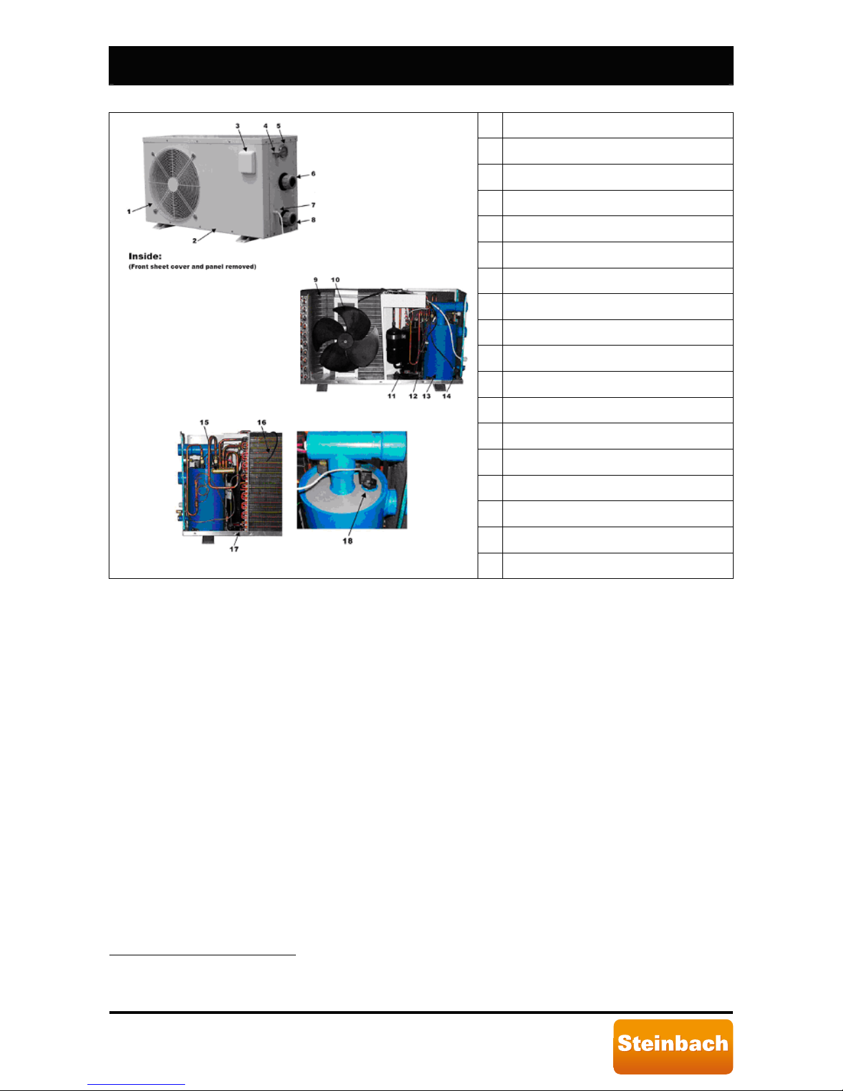
2.2. Composition.
1 Fan protection net
2 Body
3 Display
4 Refrigerant charge valve (inside for BP-35WS-B)
5 Pressure manometer
6 Water outlet
7 Power cord
8 Water inlet
9 Heat exchanger
10 Fan
11 Compressor
12 Pressure sensor
13 Heat exchanger
14 Water sensor
15
Four way valve
7
16
Ambient sensor
8
17
Plate heat exchanger temperature sensor
9
Figure 1: Main heat pump parts.
18 Flow sensor
7
Not included in model BP-xxWS-B (xx=35, 50).
8
Not included in model BP-xxWS-B (xx=35, 50).
9
Not included in model BP-xxWS-B (xx=35, 50).
Page 10
Speedheat Waterpower page 10 of 44
IRUWRGD\µVOLIHVW\OH
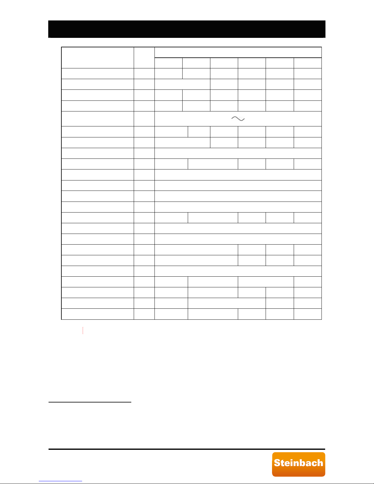
3. Technical specifications.
Mod el
Unit of
measure
BP-35WS-B BP-50WS-B BP-50HS-A BP-85HS-A BP-100HS-A BP-160HS- A
Thermal power (heating)9 [kW] 3.5 5.0 5.0 8.5 10.5 17.0
Refrigerant power ( cooling) [kW]
-10
4.3 6.8 8.5
Absorbed power11 [kW] 0. 7 5 1. 0 1.0 1.7 2.1 3.5
Absorbed current12 [A] 3.8 5.5 5.5 7.9 9.8 16
Power voltage13
[V]
[Hz]
220-240
50
COP
(Coefficient Of Performa nce)
[ ] 5.0 5.0 4.2 5.0 5.0 5.0
ERR (Energy Effic ient R atio ) [ ]
-
14
3.6 4.0 4.0 4.0
Refrigerant - R410A
Refrigerant gas quant ity [kg] 0.75 0.85 1.30 1.60 2.85
Prot ection gr ade at water input - IPX4
Number of compressors - 1
Compressor ty pe - Rotary
Heat exchanger - Titanium
Minimum water flow [m3/h] 2.5 3 3.5 4.0 6.5
Hydraulic connect ions [mm] 50
Number of fans - 1
Absorbed power by fan [W] 70 85 100 220
Fan RPM [RPM ] 830 900 850 800
Fan air flow direct ion Horizontal
Fan air flow [m3/h] 1200 1600 2000 3400
Noise [dB(A)] 50 51 53 54 60
Dimensions (L/D/H) [mm] 760x270x470 955x305x565 1005x305x610 1120 x430x790
Net/gross weight [kg] 34/38 51/54 54/57 63/67 114/124
The difference between the ambient temperature and water temperature should
never be over 15 [°C]. For this reason, do not use the heat pump when the ambient
temperature is under 15 [°C].
10
Variable according to ambient conditions.
11
Operating mode not included.
12
Variable according to ambient conditions.
13
Variable according to ambient conditions.
14
Single phase alternating current.
15
Operating mode not included.
Page 11

Speedheat Waterpower page 11 of 44
IRUWRGD\µVOLIHVW\OH
4. Installation.
The heat pump must be installed and commissioned by specialised technicians and in keeping
with current national system regulations.
Installation must be conducted evaluating all the specific site factors: vicinity and height of
walls, public accessibility, etc.
4.1. Inspection.
Upon receiving the heat pump, check packaging integrity. The machine should come with
complete manuals, for the user and for installa
tion.
4.2. Handling.
The unit is equipped with suitable protections to protect the heat pump for any damages
during handling. Avoid exerting pressure on the sides of the packaging.
Once the heat pump is unpacked, avoid exerting pressure on the body, plate heat
exchanger and fan protection net. See Figure 1
.
4.3. Positioning.
The heat pump must be positioned by specialised technicians and in keeping with current
national system regulations.
The heat pump must be carefully positioned considering the following aspects:
• Dimensions and origin of hydraulic tubes.
• Location of the power supply.
• Support and its location.
• Necessary clearance.
• Noise wave and vibration echo.
• Condensation discharge.
4.3.1. Support and its location.
The heat pump
must be installed outdoors. It cannot be installed indoors and
must be at least 3.5 [m] from the pool surface (zone 2
16
).
During normal operations, the heat pump plate heat exchanger produces
condensation. The amount of condensation produced varies according to
ambient conditions. The higher the air humidity, the higher the amount of
condensation produced. The heat pump comes with a condensation drain.
Make sure there are no obstacles to condensation draining.
The heat pump must be pos
itioned to avoid damages attributable to any water or
condensation leaks. If necessary, install suitable discharge outlets or collection
containers.
The heat pump must be installed on a solid and level support (cement slab or
prefabricated platform). Avoid positioning the heat pump on instable ground. In this
case, installing a suitably dimensioned support slab or platform is recommended.
The support surface must be slightly tilted to promot
e correct rain water and
condensation draining from the device base.
Support surface inclination must be a maximum of 2%.
Make sure the pump is not subject to rain water flows from nearby building roofs.
Protruding roofs without gutters could pour significant amounts of water and/or
debris on the heat pump which could damage it. If necessary, install gutters or
discharge outlets to protect the heat pump.
If the heat pump is installed un
der the pool level, any water leaks could cause
significant water leaks or floods. Steinbach VertriebsgmbH is not liable for any
of said leaks, floods or consequent damages.
Make sure the heat pump is not within the range of action of any irrigation systems.
If necessary, install suitable protections.
16
See CEI 64-8/7 for pool zone classifications.
Page 12
Speedheat Waterpower page 12 of 44
IRUWRGD\µVOLIHVW\OH
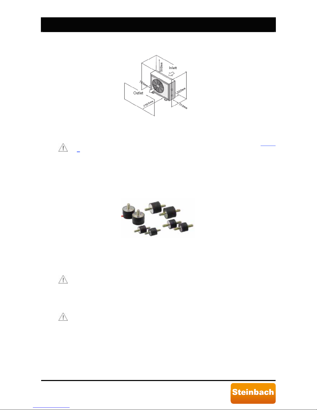
4.3.2. Necessary clearance.
Minimum clearance required for heat pump installation is illustrated in the following
figure.
Figure 2: Clearance required for correct installation.
Clearance guarantees accessibility during SERIES BP heat pump maintenance and
operations.
Avoid hot air from circulating between machine distribution and suction. See Figure
2. For this purpose, avoid all situations in which there could be an obstacle to the
free flow of air produced by the fan. Specifically, pay careful attention to the
direction of strong winds in the heat pump installation area. Strictly avoid installing
the heat pump where the direction of strong wind is contrary to heat pump flow.
4.3.3. Noise wave echo.
SERIES BP heat pumps were designed with special attention to noise and
vibrations. Retail or accessory shock absorbers can be used to diminish vibrations
and noise.
Figure 3: Shock absorber supports.
To diminish noise wave echoes, avoid positioning the pump in the immediate
vicinity of vertical walls.
4.4. Disposal.
4.4.1. General instructions.
Collecting recyclable material, both those used for packaging (cardboard, nylon,
etc.) and those replaced during routine and extraordinary maintenance is
recommended.
Suitable collection of waste material for recycling, processing and environmentally
compatible disposal contributes in avoiding possible negative effects on the
environment and health and promote the reuse and/or recycling of device materials.
Illicit product disposal by the user may be punishable by current national laws.
4.4.2. Heat pump decommissioning.
When the unit reaches the end of its working life and must be removed and/or
replaced, follow the instructions below:
o Refrigerant gas must be collected by specialised technicians and sent to
collection centres.
o Compressor lubricant oil must be collected by specialised technicians and
sent to collection centres.
Page 13
Speedheat Waterpower page 13 of 44
IRUWRGD\µVOLIHVW\OH
o The body and various parts, if unusable, should be dismantled and divided
according to their material type (for example, copper, aluminium, plastic,
etc.) and must be sent to collection centres.
4.4.3. Electric/electronic waste disposal.
In keeping “Implementation of Directives 2002/95/CE, 2002/96/CE and
2003/108/CE” on the reduction of the use of hazardous substances in
electric and electronic material as well as waste disposal. The barred bin
symbol on the equipment or packaging indicates that the product must
be separated from other waste at the end of its working life. Therefore,
the user must take equipment to electronic and electro-technical waste collection
centres at the end of its working life or return it to the dealer when purchasing similar
new equipment, on a one to one basis. Suitable collection of decommissioned
equipment for recycling, processing and environmentally compatible disposal
contributes in avoiding possible negative effects on the environment and health and
promote the reuse and/or recycling of device materials. Illicit product disposal by the
user may be punishable by current national laws.
4.5. Hydraulic connections.
4.5.1. Warnings.
The heat pump hydraulic connections must be performed by specialised technicians
and in keeping with current national system regulations.
During hydraulic connections, avoid using free flames near or within the heat pump.
The following retail components are recommended for hydraulic connections:
• Cut-off valves upstream and downstream from the heat pump to facilitate
maintenance and/or heat pump bypass from the pool hydraulic system.
• Hydraulic circuit charge and drain valve for the heat pump.
• Hydraulic circuit bypass valve, see Figure 6
.
• Mechanical filter upstream from the heat pump, usually a sand filter.
• Non-return valve, installed between the pool and the heat pump output fitting,
to prevent water reflux.
Tubes that have the same diameter of the heat pump inlet and outlet are
recommended for upstream and downstream heat pump connections.
During periods of heat pump disuse, for example, during the winter, drain water
from the heat pump circuit and heat pump.
Chemical dosing devices, when applicable, must be installed downstream from the
heat pump and non-return valve. This prevent chemically saturated water reflux
which could damage the heat pump.
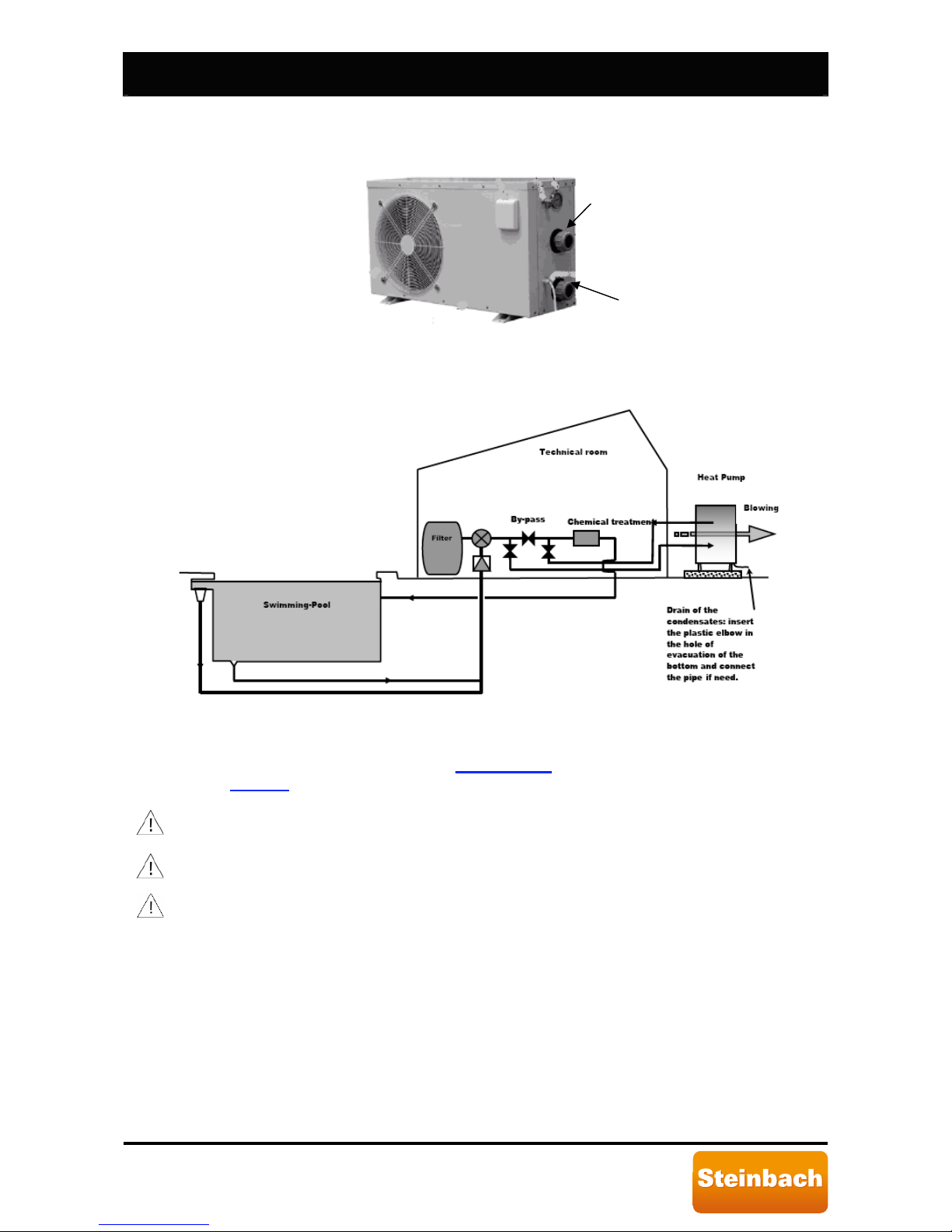
4.5.2. Installation hydraulic layout.
The hydraulic circuit where the heat pump is installed must be created observing
the following general layout.
Swimming pool
Chemical regulator
Non-return valve
Heat pump
Filter
Pump
Swimming pool
Figure 4: General hydraulic circuit layout.
Page 14
Speedheat Waterpower page 14 of 44
IRUWRGD\µVOLIHVW\OH
The pump must be hydraulically connected with PVC tubes with 50 [mm] external
diameters. Tubes must be inserted in the fittings for about 1÷2 [cm] and secured
with the supplied fast connections.
Figure 5: Hydraulic connections.
The hydraulic circuit is usually created as illustrated in the following figure.
Figure 6: Typical hydraulic circuit part layout.
Minimum heat pump water input flow must not be under the value required for
the model in question. See Paragraph 2
. For system layouts such as that in
Figure 6
, water flow can be regulated using the bypass valve.
4.6. Electrical connections.
The heat pump electrical connections must be performed by specialised
technicians and in keeping with current national system regulations.
Working on live electrical equipment is prohibited. Before starting work, make sure
the heat pump is disconnected from the electrical mains.
Modifying electrical connections inside the heat pump without Steinbach VertriebsgmbH
authorisation is str
ictly prohibited.
Power voltage must not vary more than 10 % from the nominal value. It must be within the
207÷253 [V] interval. If power voltage is subject to frequent variations, contact specialised
technicians for suitable protection devices.
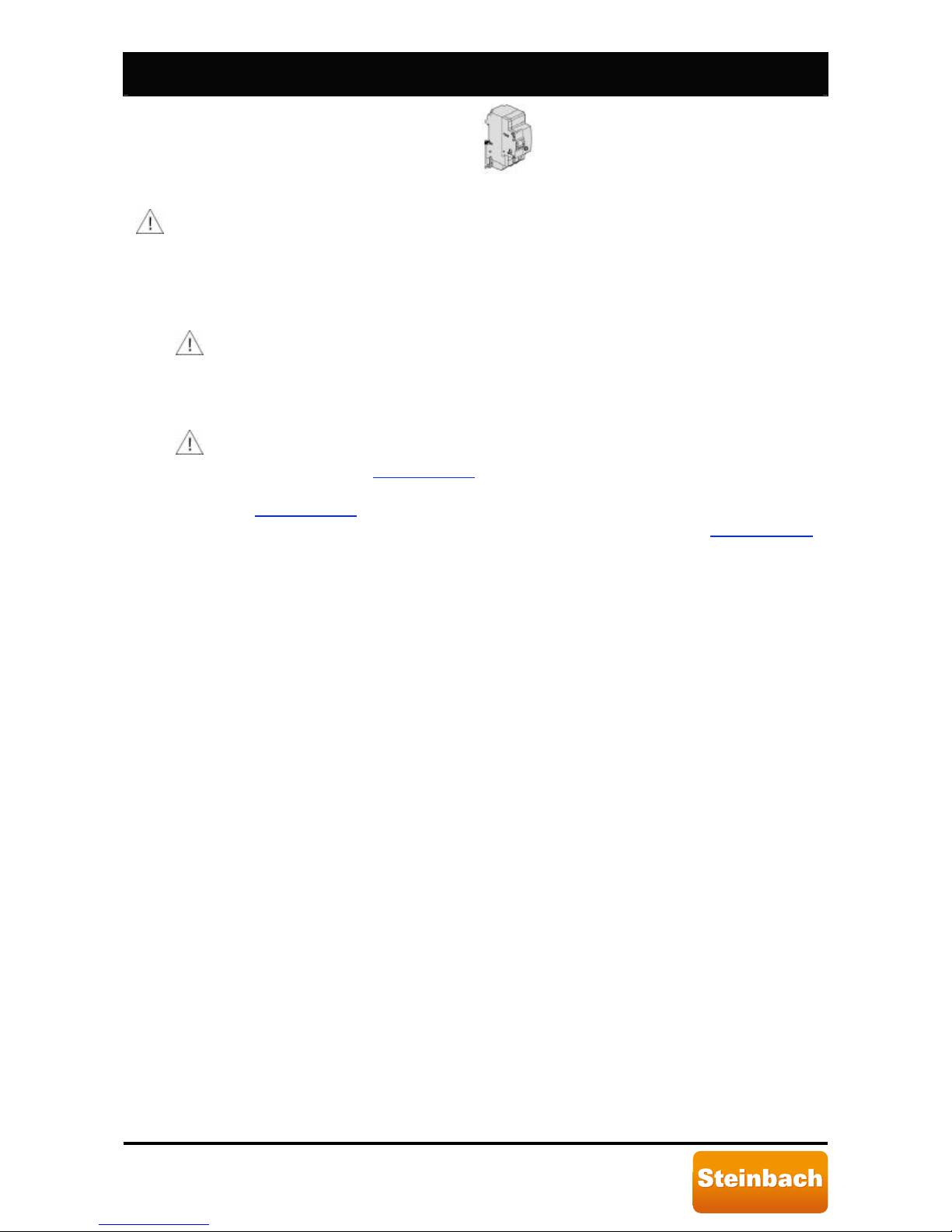
Install a protection device, circuit breaker with delayed type 16 [A] fuse, upstream from the
heat pump. This protection device must only service the heat pump. Furthermore, install a
contact s
witch protection device, circuit breaker, that has nominal operating differential
current not over 30 [mA].
Output fitting
Input fitting
Page 15
Speedheat Waterpower page 15 of 44
IRUWRGD\µVOLIHVW\OH
Figure 7: Protection device and/or contact switch.
The electrical mains connected to the heat pump must be grounded.
If a socket is installed for electrical mains connections, the latter must have a protection
grade no lower than IPX4 and must have a grounding terminal. The same applies for the
mains which must be grounded.
4.7. Commissioning, preliminary checks.
4.7.1. Commissioning, precautions.
Before starting the pump, make s
ure there is water in the pool, that the skimmer and
suction fittings, when installed, are submerged, that the cut-off valves do not prevent
water flow from the pool to the heat pump and vice versa and that the circulation
pump is on.
4.7.2. First start-up, preliminary checks.
At first heat pump start-up, make sure that:
o the electrical mains were connected in keeping with current national system
regulations, see Paragraph
4.6
.
o there are no refrigerant fluid leaks checking the pressure on the manometer, see
Paragraph 5.3
, using leak detection devices.
o Make sure hydraulic connections were correctly performed, see Paragraph 4.5
.
o Make sure all body panels are in place and locked with screws.
o Make sure there are no impediments to free water flow from the pool to the heat
pump and vice versa.
Page 16
Speedheat Waterpower page 16 of 44
IRUWRGD\µVOLIHVW\OH
5. Operations and use.
5.1. Introduction.
Please read the paragraph on energy savings, see Paragraph 1.5
.
SERIES BP heat pumps are equipped with control boards which, thanks to a simple but
functional interface, allow heat pump programming to guarantee efficient service.
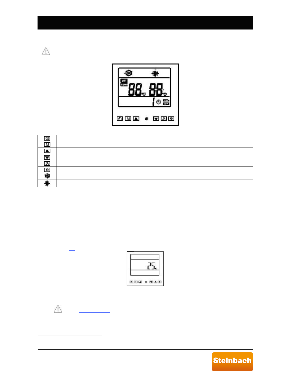
Figure 8: Heat pump panel.
Heat pump on/off button.
Operating mode selection button (heating/cooling
17
) or operating parameter programming access.
Up button.
Down button.
Multi-function button.
Timer or temperature control on/off button.
Heat pump operating mode indication: cooling
18
.
Heat pump operating mode indication: heating.
Table 1: Control panel display symbol key.
5.2. Control panel use.
The control panel displays all information required for the user, data and/or error
messages. Please see Paragraph 7.5
.
5.2.1. Turning on the heat pump.
Use the protection device and/or contact switch to turn on the heat pump. Please
see Paragraph 4.6
.
5.2.2. Standby.
Water temperature is displayed when the heat pump is turned on. Please see Figure
12. The heat pump is in standby conditions. It does not heat or cool pool water.
Figure 9: Heat pump display in standby conditions.
5.2.3. Turning off the heat pump.
Use the protection device and/or contact switch to turn off the heat pump. Please
see Paragraph 4.6
. Make sure the heat pump is in standby before turning it off.
17
The BP-xxWS-B (xx=35, 50) model has only one operating mode: heating.
18
Operating mode not included in model BP-xxWS-B (xx=35, 50).
Page 17
Speedheat Waterpower page 17 of 44
IRUWRGD\µVOLIHVW\OH
5.2.4. Starting the heat pump.
To start the heat pump, press
. The heat pump starts within 3 minutes. The last
selected operating mode (heating or cooling
19
), see Figure 13
. Figure 14 and
Paragraph 5.2.13.8
, the last temperature set and the current pool water temperature
(heating or cooling) is immediately displayed.
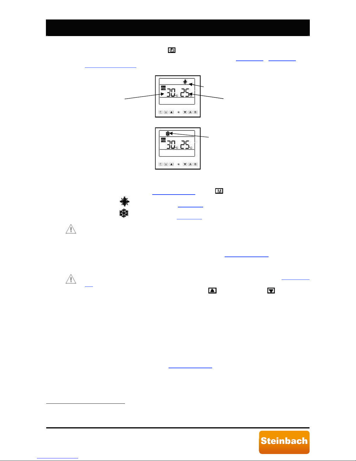
Figure 10: Heat pump display when turned on, heating mode.
Figure 11: Heat pump display when turned on, cooling mode.
5.2.5. Operating mode selection20.
Start the heat pump, see Paragraph 5.2.4
, press to select the operating mode:
• Heating,
is displayed, see Figure 13.
• Cooling, is displayed, see Figure 14.
Whenever the operating mode changes, the set temperature is switched to the
following default values:
• Heating mode, 40 [°C].
• Cooling mode, 30 [°C].
Thus, the set temperature must be regulated, see Paragraph 5.2.6
, whenever the
operating mode changes.
5.2.6. Set temperature regulation.
Before regulating the set temperature, carefully read the instructions in Paragraph
1.4.
Set temperature can be regulated by pressing
, to increase it and , to decrease
it. Set temperature can be selected in the interval 5÷45 [°C].
Parameter programming, upon heat pump assembly, guarantees that the difference
between pool water temperature and set temperature is never over 3 [°C] as
illustrated by the following examples:
• Heating mode, set temperature 30 [°C], pool water temperature is never under
27 [°C].
• Cooling mode, set temperature 15 [°C], pool water temperatur
e is never over 18
[°C].
5.2.7. Minimum working temperature and restart temperature
21
.
Once the pump is started, see Paragraph 5.2.4
. if the ambient temperature is lower
than the minimum working temperature, the heat pump stops, displaying error
message “EE C”, and only restarts if the ambient temperature exceeds the restart
temperature. When the pump is constructed, the minimum working temperature and
19
Operating mode not included in model BP-xxWS-B (xx=35, 50).
20
Not included in model BP-xxWS-B (xx=35, 50).
21
Not included in model BP-xxWS-B (xx=35, 50).
Heating mode
Current pool water temperature
Set temperature
Cooling mode
Page 18
Speedheat Waterpower page 18 of 44
IRUWRGD\µVOLIHVW\OH
restart temperature are a –15 [°C] and –13 [°C] respectively, minimum admissible
values.
The minimum working temperature must be at least 2° C lower than the restart
temperature.
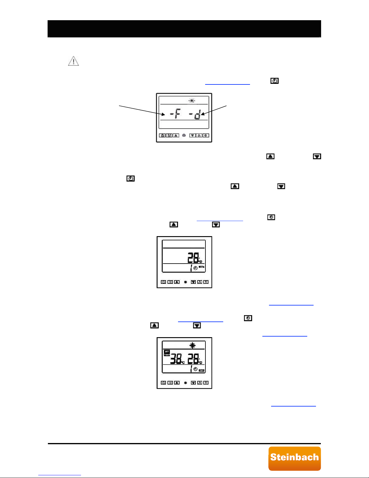
Proceed as follows to set minimum working temperature:
o When the pump is in standby, see Paragraph 5.2.2
, press and hold down
for 3 seconds.
Figure 12: Minimum working temperature and restart temperature.
o Regulate minimum working temperature with keys
(increase),
(decrease). Minimum working temperature cannot be under –15 [°C] (-F),
the regulation interval for minimum working temperature is -15÷+97 [°C].
o Press
, to regulate the restart temperature.
o Regulate restart temperature with keys
(increase), (decrease).
Minimum restart temperature cannot be under -13 [°C] (-d), the regulation
interval for restart temperature is -13÷99 [°C].
5.2.8. Automatic start settings.
When the pump is in standby, see Paragraph 5.2.2
, press to turn on the
automatic start mode. Press
(increase), (decrease) to select when the heat
pump should automatically start (1÷24 hours).
Figure 13: Automatic start settings.
Automatic start can only be set when the pump is in standby, see Paragraph 5.2.4
.
5.2.9. Automatic standby settings.
When the pump is running, see Paragraph 5.2.4
, press to turn on the automatic
standby mode. Press
(increase), (decrease) to select when the heat pump
should automatically return to standby mode (1÷24 hours), see Paragraph 5.2.2
.
Figure 14: Automatic standby settings.
Automatic standby can only be set when the pump is running, see Paragraph 5.2.4
.
Restart temperature
Minimum working
temperature
Page 19
Speedheat Waterpower page 19 of 44
IRUWRGD\µVOLIHVW\OH
5.2.10. Manual defrost
22
.
Frost may form on the plate heat exchanger during normal operations in heating
mode, see Figure 1
. Frost on the plate heat exchanger reduces heat pump
performance. Frost is formed during heating mode because the heat pump cools
surrounding ambient air to heat water. SERIES BP pumps are equipped with a
temperature sensor that detects frost on the plate heat exchanger and starts
automatic defrost. However, if this is insufficient, manual defrost can be started.
Manual defrost can only be started when the heat pump is running in heating
mode.
When the pump is running, see Paragraph 5.2.4
, press and hold down for 5
seconds to turn on manual defrost. Manual defrost lasts several minutes. At the
end of the manual defrost cycle, the heat pump automatically starts.
When defrosting, refrigerant fluid pressure is increased to make refrigerant fluid
hotter so that it heats the plate heat exchanger during circulation to defrost.
When defrosting, refrigerant fluid pressure significantly increases. For further
information, see Paragraph 5.3
.
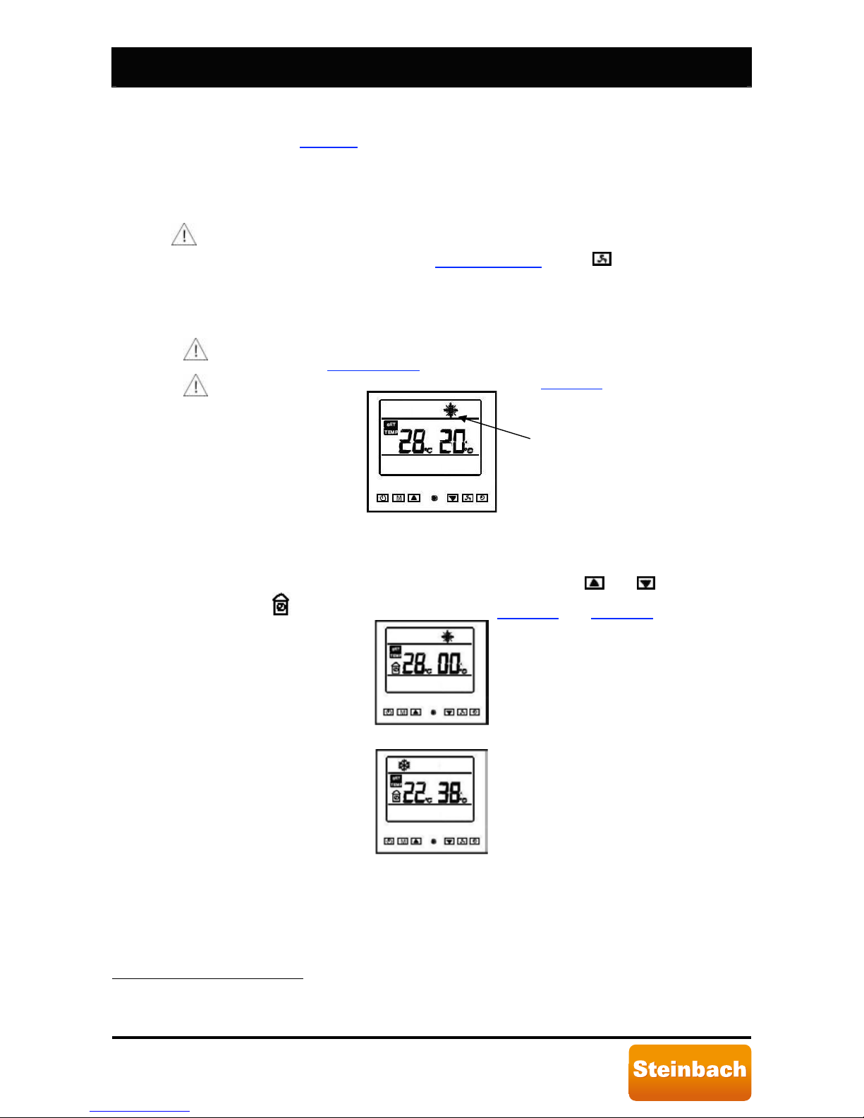
The heating mode icon blinks during defrost. See Figure 18
.
Figure 15: Manual defrost.
5.2.11. Key lock.
Keys can be locked to prevent accidental regulations.
To lock keys, press and simultaneously hold down keys
and for 5 seconds.
Symbol
will appear on the display. See Figure 19 and Figure 20.
Figure 16: Key lock, heating mode.
Figure 17: Key lock, cooling mode.
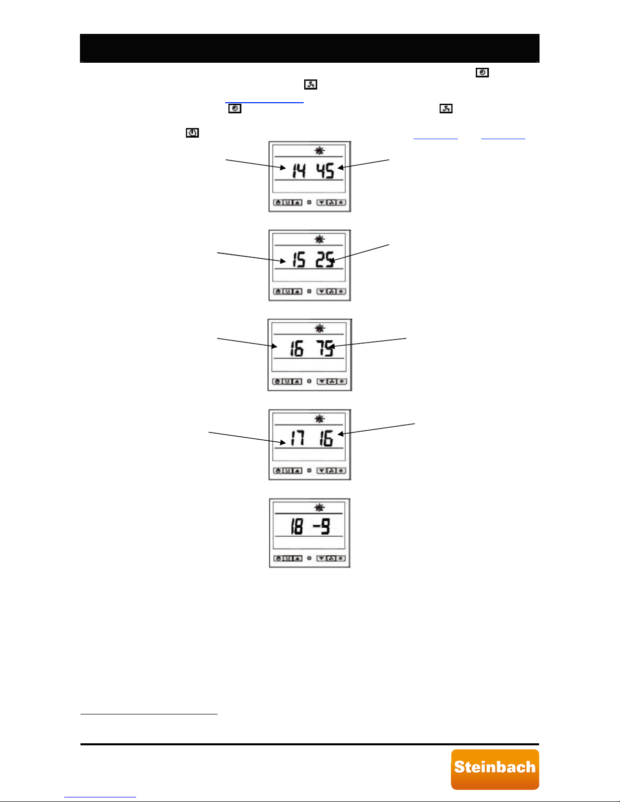
5.2.12. Sensor temperature display.
SERIES BP heat pumps are equipped with 4 temperature sensors that
continuously read pool water, ambient
23
, compressor and plate heat exchanger
temperatures
24
.
22
Operating mode not included in model BP-xxWS-B (xx=35, 50).
23
Not included in model BP-xxWS-B (xx=35, 50) where the sensor is not installed.
24
Not included in model BP-xxWS-B (xx=35, 50) where the sensor is not installed.
blinks
Page 20
Speedheat Waterpower page 20 of 44
IRUWRGD\µVOLIHVW\OH
The temperature read by each sensor can be displayed by pressing (for model
BP-xxWS-B (xx=35, 50), press
) and hold down for 3 seconds with the pump is
running, see Paragraph 5.2.4
. To display temperatures read by the various
sensors, press
(for model BP-xxWS-B (xx=35, 50), press ). The temperature
read by the sensor is displayed for 10 seconds, if no other key is pressed, or
press
to return usual information to the display, see Figure 13 and Figure 14.
Figure 18: Pool water temperature sensor.
Figure 19: Ambient temperature sensor25.
Figure 20: Compressor temperature sensor.
Figure 21: Condenser temperature sensor.
Figure 22: Sensor not used26.
5.3. Manometer use.
SERIES BP heat pumps are equipped with a manometer that displays refrigerant fluid
pressure in the high pressure circuit.
Typical pressure values are the following:
• Heat pump off or in standby, the indicated pressure is between 14÷16 [bar] ([kg/cm
2
]);
• Heat pump running, the indicated pressure is between 21÷35 [bar] ([kg/cm
2
]).
When defrosting, refrigerant fluid pressure is increased to make refrigerant fluid hotter so
that it heats the plate heat exchanger during circulation to defrost. Defrosting lasts several
minutes.
Temperature read
Temperature read
Temperature read
Temperature read
Pool water
temperature sensor
number
Condenser
temperature sensor
number
Compressor
temperature sensor
number
Ambient temperature
sensor number
25
For model BP-xxWS-B (xx=35, 50), parameter 15 indicates the compressor temperature sensor.
26
Not used for SERIES BP heat pump control.
Page 21
Speedheat Waterpower page 21 of 44
IRUWRGD\µVOLIHVW\OH
6. Control and safety devices.
6.1. Control devices.
6.1.1. Ambient
27
and pool temperature sensors.
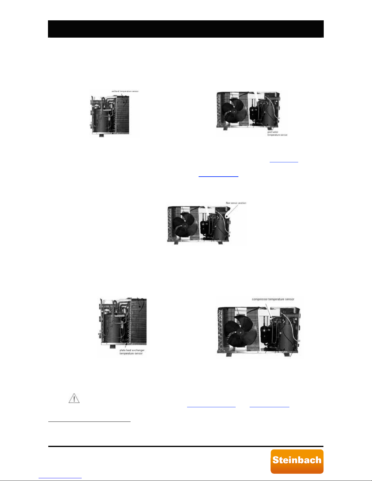
SERIES BP control pumps are equipped with sensors that continuously check
ambient and pool water temperatures. The sensors are located as illustrated in the
following figures.
Figure 24: Ambient temperature sensor.
Figure 25: Pool water temperature sensor.
Temperature sensors are connected to connector CN4 (ambient temperature and
water temperature) as indicated in the wiring diagram, see Figure 10
. Sensor
operations can be checked by measuring the resistance when temperature
changes. Usual values are indicated in Paragraph 6.3
.
6.1.2. Flow sensor.
SERIES BP control pumps are equipped with a flow sensor that continuously reads
water flow. The sensor is located as illustrated in the following figure.
Figure 26: Flow sensor position.
6.2. Safety devices.
6.2.1. Compressor and plate heat exchanger temperature sensors
28
.
SERIES BP heat pumps are equipped with 2 temperature sensors that continuously
read compressor and plate heat exchanger temperatures. The sensors are located
as illustrated in the following figures.
Figure 27: Plate heat exchanger temperature sensor.
Figure 28: Compressor temperature sensor.
6.2.2. High pressure sensor.
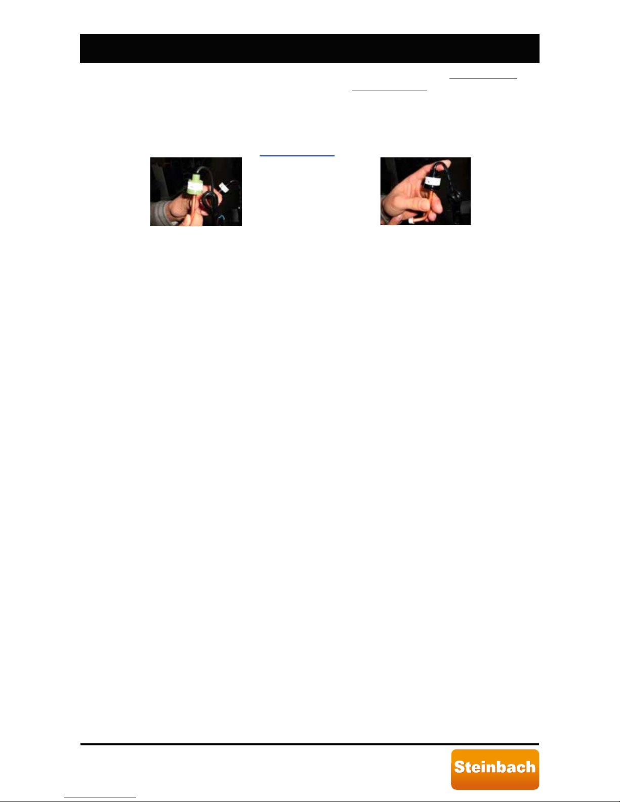
The high pressure sensor stops the compressor when supply pressure, in the
refrigerant circuit high pressure section, exceeds the calibration value.
The high pressure sensor signal is not considered during either manual or automatic
defrost. For further information see Paragraph 5.2.10
and Paragraph 5.3.
27
Not included in model BP-xxWS-B (xx=35, 50).
28
Not necessary in model BP-xxWS-B (xx=35, 50) since there is no plate heat exchanger defrost
process.
Page 22
Speedheat Waterpower page 22 of 44
IRUWRGD\µVOLIHVW\OH
Trigger pressure is 4.2 [bar]. After a high pressure alarm, see Paragraph 7.5, the
heat pump must be manually restarted, see Paragraph 5.2.4
.
6.2.3. Low pressure sensor.
The low pressure sensor stops the compressor when suction pressure in the high
pressure section is under the calibration value.
Trigger pressure is 0.05 [bar]. After a low pressure alarm, the heat pump must be
manually restarted, see Paragraph 5.2.4
.
Figure 27: High pressure sensor.
Figure 28: Low pressure sensor.
Page 23

Speedheat Waterpower page 23 of 44
IRUWRGD\µVOLIHVW\OH
7. Routine, scheduled and extraordinary maintenance.
Periodic controls are required to keep SERIES BP heat pumps in good working order and to
guarantee the foreseen performance and safety levels. Some controls can be performed by the
user while specialised technicians are required for others.
During normal operations, the heat pump plate heat exchanger produces condensation.
The amount of condensation produced varies according to ambient conditions. The
higher the air humidity, the higher the amount of condensation produced. The lower
heat pump panel acts as a condensation collection tray. Keep the drain hole clean.
7.1. User controls.
SERIES BP heat pump users must periodically make sure that:
• Dirt is not accumulated near the heat pump (leaves, paper, etc.). Performing this
control weekly is recommended. Use caution when nearing the plate heat
exchanger blade since rather sharp.
• There are no leaks in the hydraulic circuit. Conduct this control monthly.
• Electrical mains wires and connections are integral, Performing this control monthly
is recommended.
• The correct chemical balance in the pool water is guaranteed in order to guarantee
hygienic accessibility conditions and long heat pump life. Conducting this control
daily with specific retail kits is recommended.
• The pressure values indicated on the manometer are correct. See Paragraph 5.3
.
• Make sure the condensation drain hole is open.
7.2. Specialised technician controls.
The following controls must be conducted by a specialised technician at least once a year
to guarantee safe and efficient SERIES BP heat pump operations:
• Electrical mains wire and connection integrity.
• Hydraulic system integrity.
• Inspect and clean the plate heat exchanger coil.
• Check correct heat pump operations, start, see Paragraph 5.2.4
.
• Check usual pressure values indicated by the manometer, see Paragraph 5.3
.
• Make sure there are no oil leaks from the compressor.
7.3. Winter protection.
The following instructions must be observed to protect SERIES BP heat pumps for the
winter:
• Disconnect the electrical mains using the protection device and/or contact switch,
see Paragraph 5.2.3
.
• Drain the heat pump hydraulic system using the cut-off valve, see Paragraph 4.5
.
• Protect the plate heat exchanger and fan from dirt accumulation. Do not wrap the
heat pump with plastic or other material that can hold heat and/or humidity inside
the device.
7.4. Spring commissioning.
The following instructions must be observed for SERIES BP heat pump spring
commissioning.
• Remove any protections used for winter protection, see Paragraph 7.3
.
• Fill the heat pump hydraulic system using the cut-off valve, see Paragraph 4.5
.
• Check the water chemical composition, see Paragraph 7.1
, act accordingly if
necessary.
• Restore the electrical mains using the protection device and/or contact switch, see
Paragraph 4.6
.
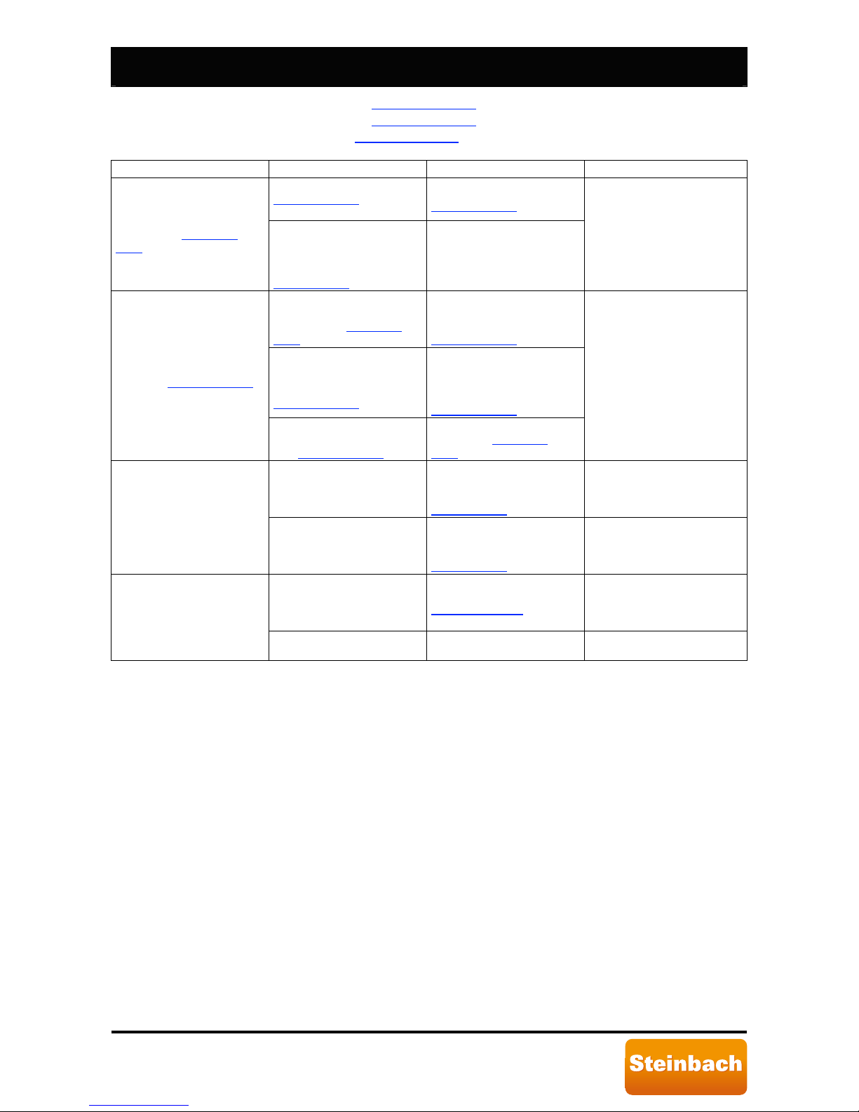
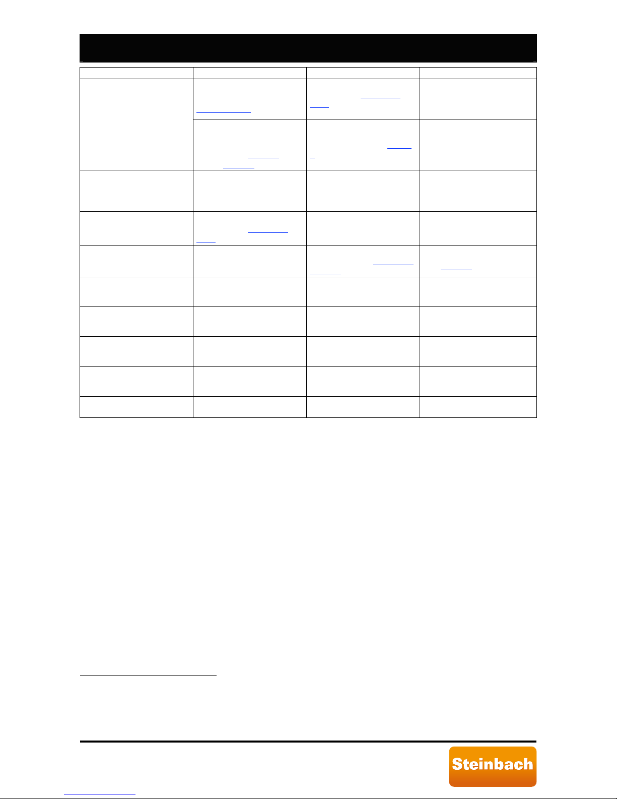
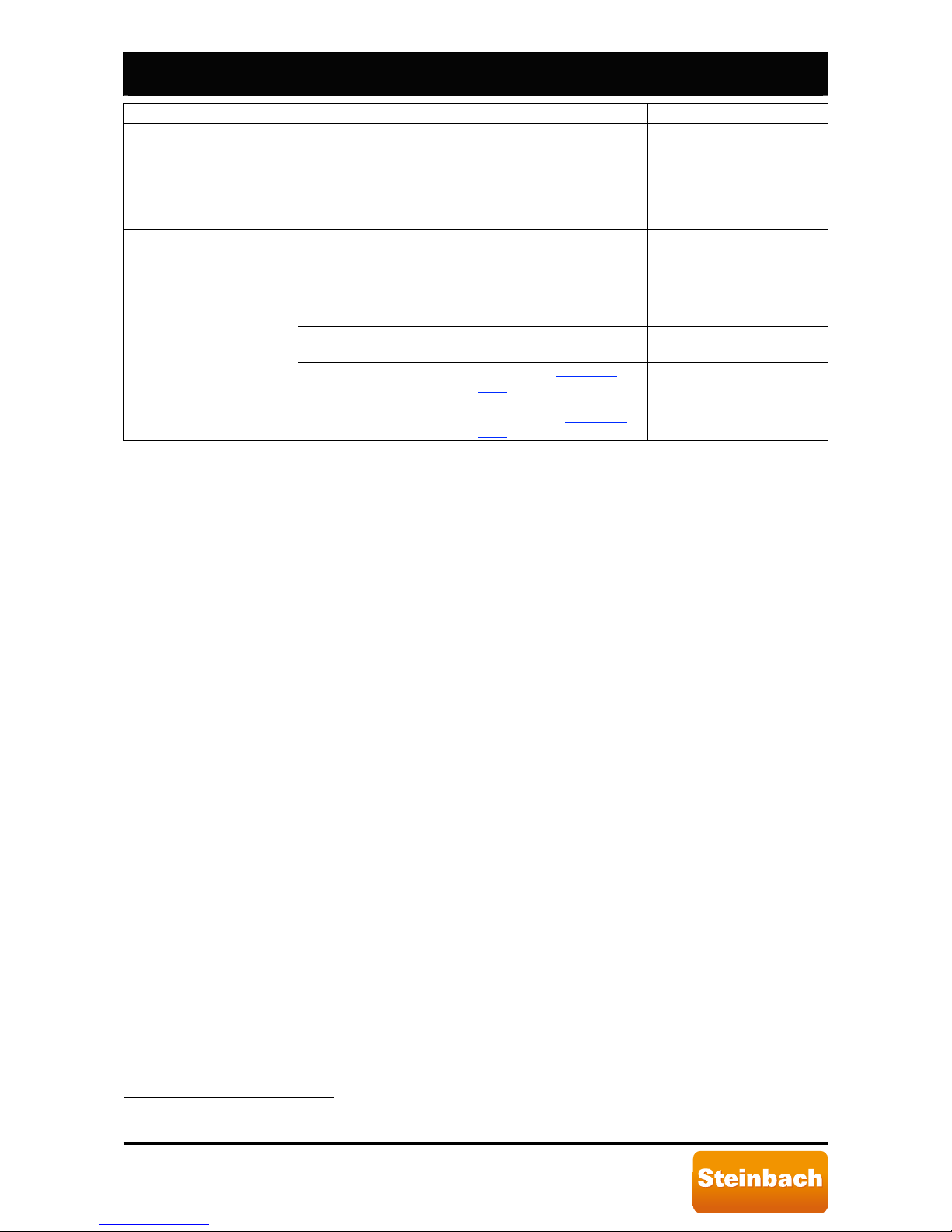
7.5. Troubleshooting.
The following table can be used to solve main heat pump problems. When a message
error is displayed, the following is required to restore operations:
Page 24
Speedheat Waterpower page 24 of 44
IRUWRGD\µVOLIHVW\OH
- turn off the heat pump, see Paragraph 5.2.3;
- turn on the heat pump, see Paragraph 5.2.1
;
- start the heat pump, see Paragraph 5.2.4
.
Problem
Possible cause 1
st
solution 2nd solution
The instructions in
Paragraph 5.2.1
were not
followed.
Follow the instructions in
Paragraph 5.2.1
The heat pump does not
turn on, see Paragraph
5.2.1.
The mains connection line
protection device fuse is
burned out or the contact
switch triggered, see
Paragraph 4.6
.
Reset the switch and/or
replace the fuse.
The 3 minutes required for
pump start have not
elapsed. See Paragraph
5.2.4.
Wait until the 3 minutes
required for pump start
have elapsed. See
Paragraph 5.2.4
.
Pool temperature is greater
than or equal to set
temperature. See
Paragraph 5.2.6
.
The pump will start when
the pool temperature is
lower than the set
temperature. See
Paragraph 5.2.6
.
The heat pump does not
start, see Paragraph 5.2.6
.
The pump operating mode
is not the required mode.
See Paragraph 5.2.5
.
Set the required operating
mode. See Paragraph
5.2.5.
The heat pump was just
installed.
24÷48 hours may be
required to reach the set
temperature. See
Paragraph 1.5
.
Contact specialised
technicians.
The heat pump is running
but the water is not heating.
Pool water has significantly
cooled since the last heat
pump use.
24÷36 hours may be
required to reach the set
temperature. See
Paragraph 1.5
.
Contact specialised
technicians.
Too low ambient
temperature and/or a
significant amount of
humidity in the air.
Start manual defrost. See
Paragraph 5.2.10
.
There is frost on the plate
heat exchanger.
Pressure refrigerant drop
down.
Contact specialised
technicians.
Page 25
Speedheat Waterpower page 25 of 44
IRUWRGD\µVOLIHVW\OH
Problem
Possible cause
1
st
solution 2nd solution
Probable accumulation of
condensation. See
Paragraph 4.3
.
Put the heat pump in
standby, see Paragraph
5.2.2, if the leak stops, this
is normal condensation.
Water leaks from the heat
pump.
Possible water leak from
the water exchanger or from
hydraulic unit connection
devices. See Figure 1
and/or Figure 5
.
Tighten the fastening nut,
for an example, see Figure
5.
Error message EE b is
displayed.
Insufficient water flow
Increase water flow in the
hydraulic circuit that
supplies the heat pump.
After 2 minutes restart.
Contact specialised
technicians.
Error message EE c is
displayed.
Ambient temperature under
-15 [°C]. See Paragraph
5.2.7.
Wait until ambient
temperature rises to start
the heat pump.
Contact specialised
technicians.
Error message EE d is
displayed.
Functional parameter
changes. Parameter 9 is not
set to 0.
Set correct parameter
values to 1. See Paragraph
5.2.13.7.
Replace the control board.
See Figure 9
.
The heat pump does not
work
29
and error message
EE 1 is displayed.
Contact specialised
technicians.
The heat pump does not
work
30
and error message
EE 2 is displayed.
Contact specialised
technicians.
The heat pump is running
work
31
and error message
EE 3 is displayed.
Contact specialised
technicians.
The heat pump is running
32
and error message EE 4 is
displayed.
Automatic defrost did not
run correctly.
Increase water flow at pump
inlet.
Contact specialised
technicians.
Error message EE 5 is
displayed.
33
Contact specialised
technicians.
29
Compressor and fan off.
30
Compressor and fan off.
31
Compressor and fan on.
32
Compressor and fan on.
33
This error message is not used and should not be displayed.
Page 26
Speedheat Waterpower page 26 of 44
IRUWRGD\µVOLIHVW\OH
Problem
Possible cause
1
st
solution 2nd solution
The heat pump does not
work
34
and error message
EE 6 is displayed.
Compressor temperature
too high.
Wait until compressor
temperature drops.
Contact specialised
technicians.
The heat pump does not
work
35
and error message
EE 7 is displayed.
Contact specialised
technicians.
The heat pump does not
work and error message EE
8 is displayed.
Contact specialised
technicians.
Pool temperature too high.
Wait until pool temperature
drops.
Contact specialised
technicians.
Ambient temperature too
high.
Wait until ambient
temperature drops.
Contact specialised
technicians.
Error message EE 9 is
displayed.
Manual defrost started
without frost on plate heat
exchanger
Turn off, see Paragraph
5.2.3, turn on, see
Paragraph 5.2.1
, and start
the pump, see Paragraph
5.2.4
34
Compressor and fan off.
35
Compressor and fan off.
Page 27
Speedheat Waterpower page 27 of 44
IRUWRGD\µVOLIHVW\OH
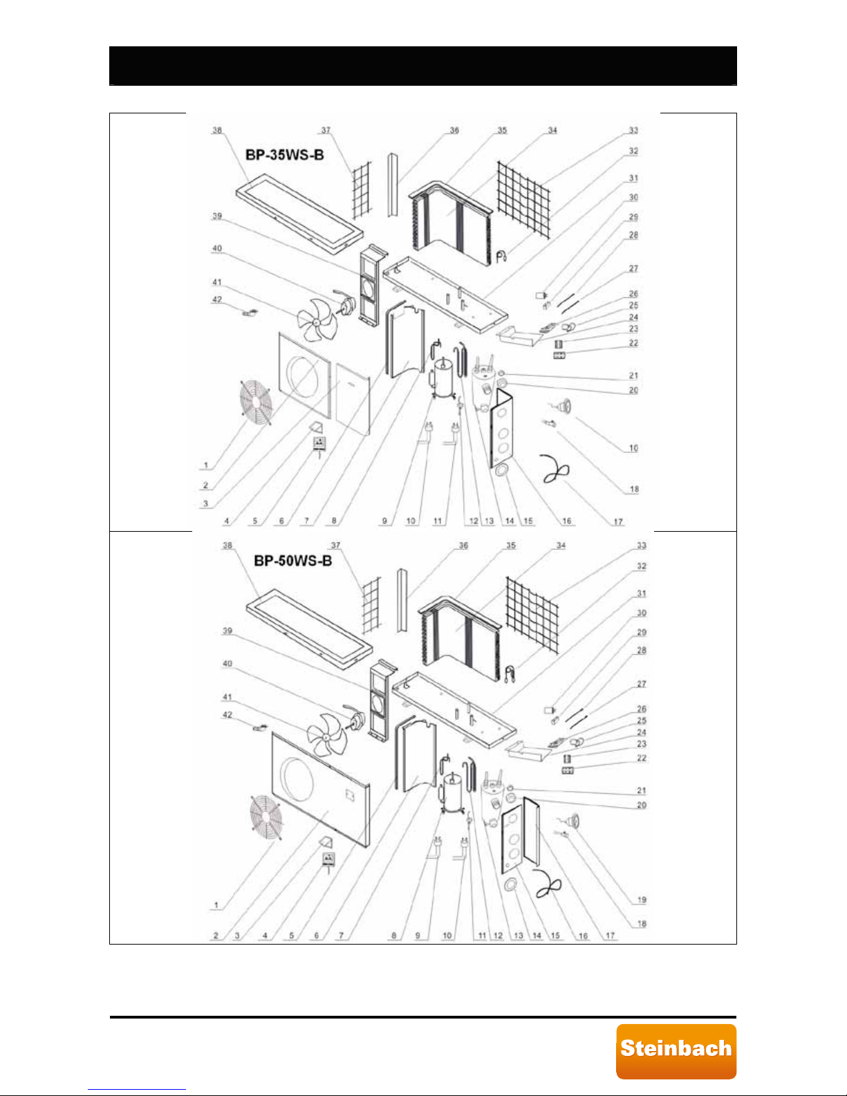
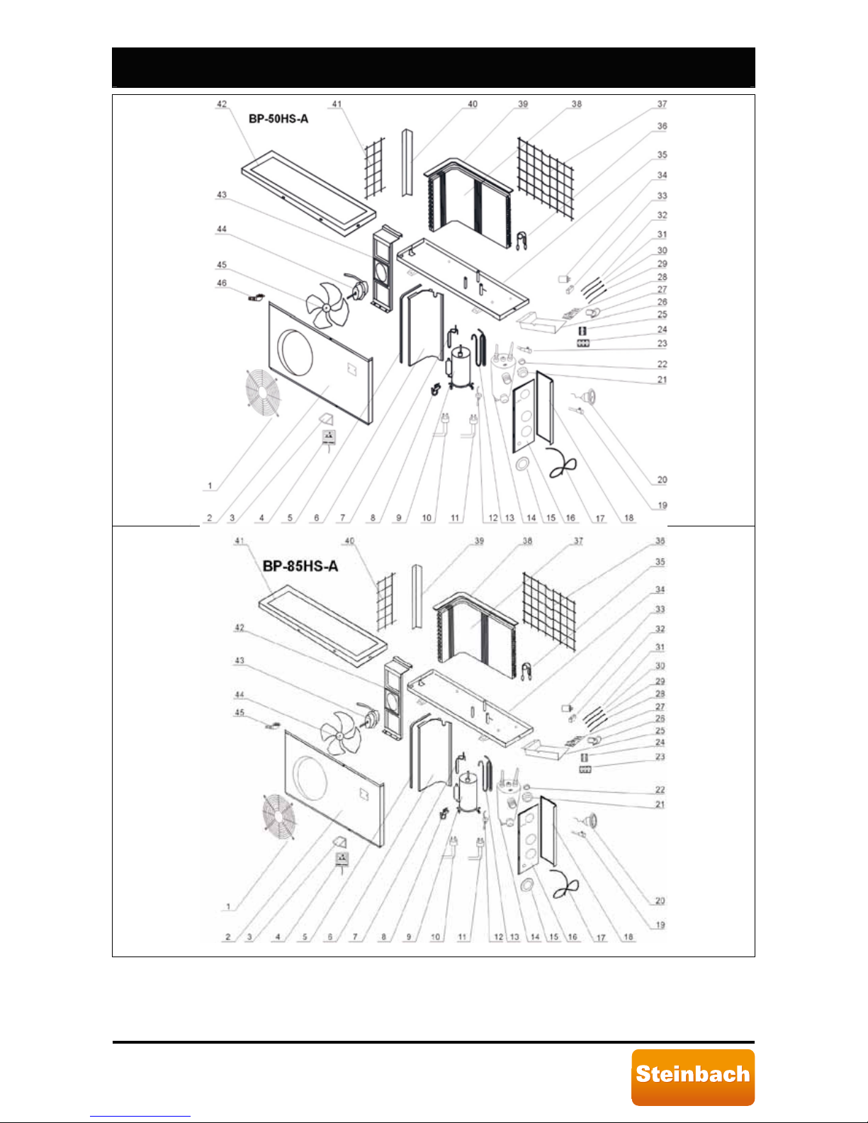
8. Spare parts.
Page 28
Speedheat Waterpower page 28 of 44
IRUWRGD\µVOLIHVW\OH
Page 29
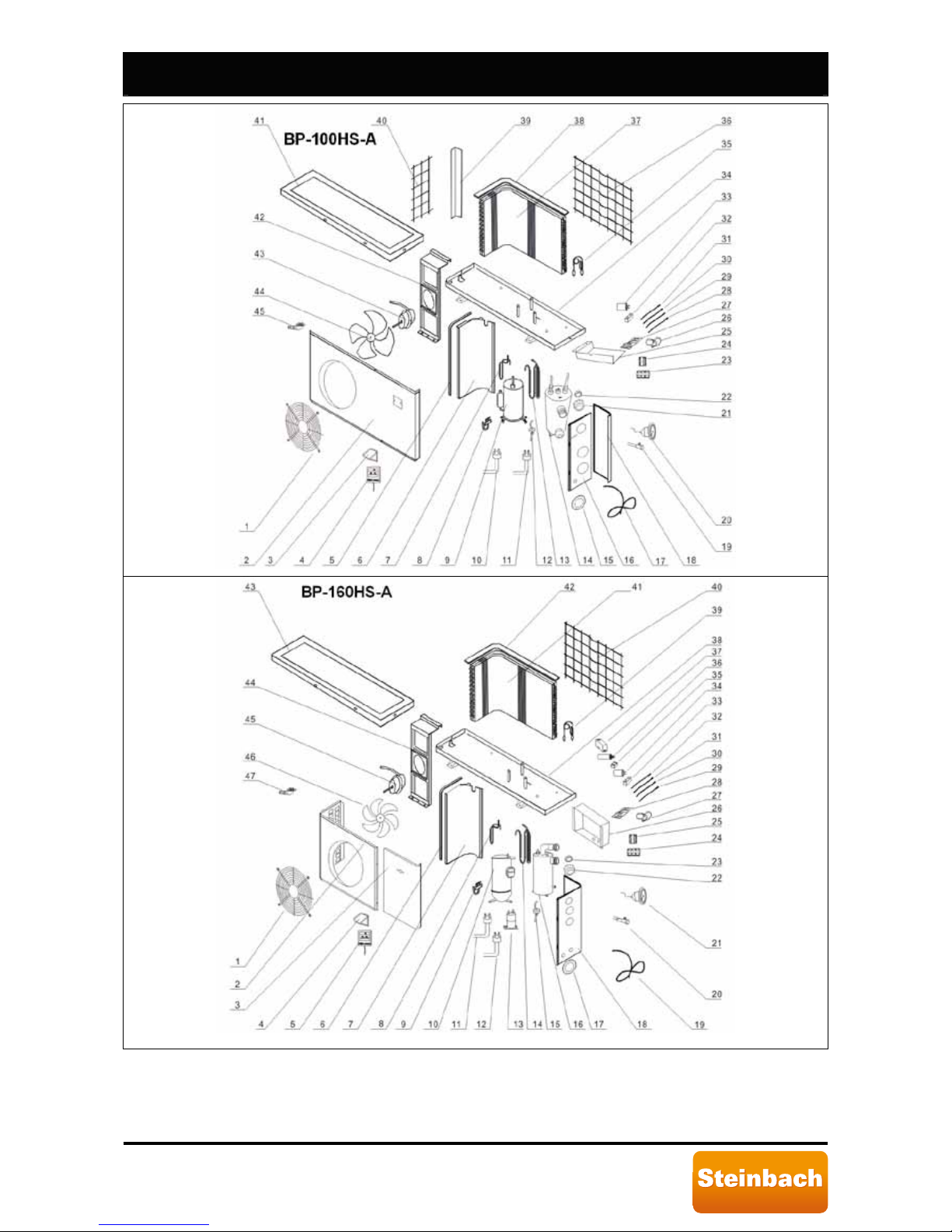
Speedheat Waterpower page 29 of 44
IRUWRGD\µVOLIHVW\OH
Page 30
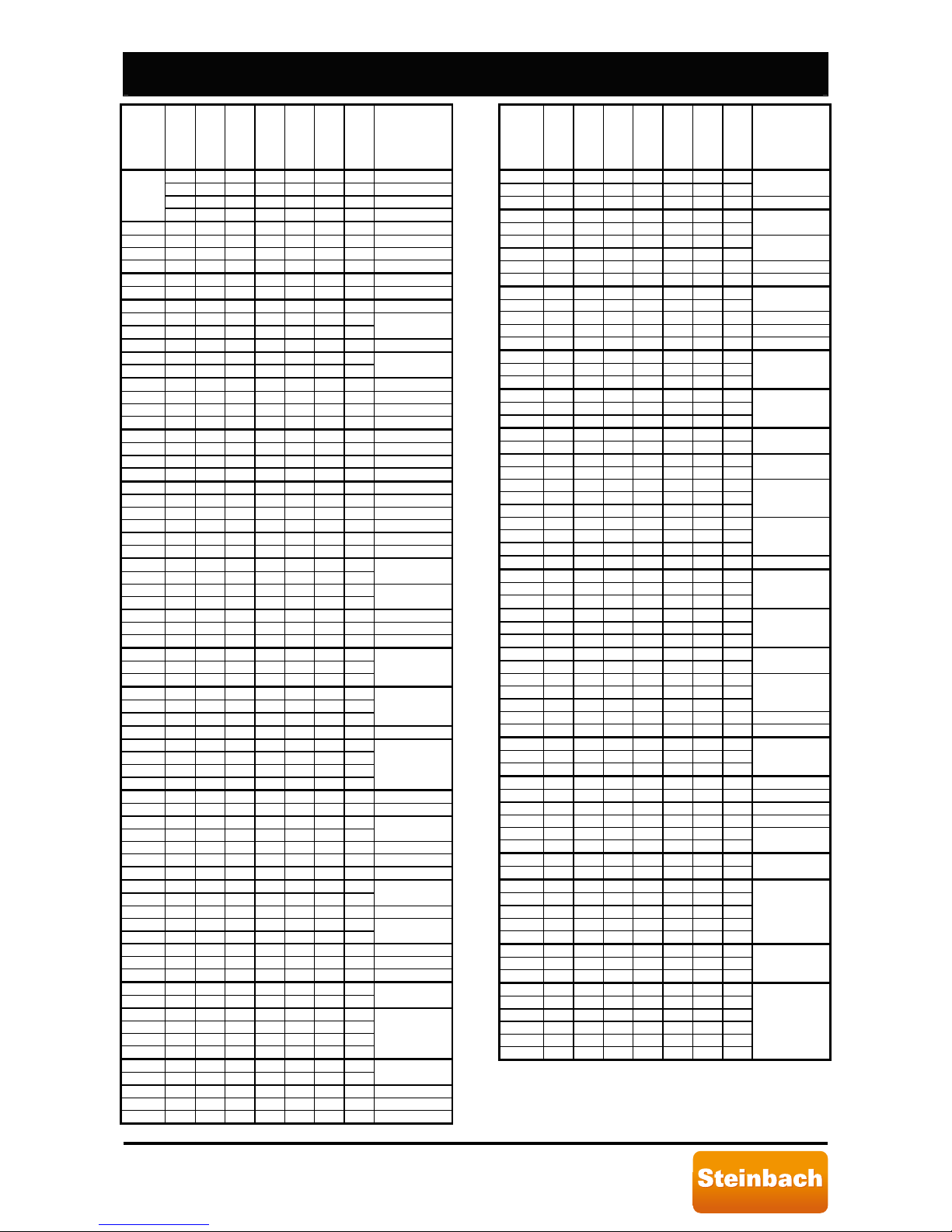
Speedheat Waterpower page 30 of 44
IRUWRGD\µVOLIHVW\OH
#
BP-35WS-B
BP-35HS-A
BP-50WS-B
BP-50HS-A
BP-85HS-A
BP-100HS-A
BP-160HS-A
X XW35HSI001A
X X X XW 50HSI001A
X XW100HSI001A
1
X XW160HSI001A
2 X X XW35HSI002A
3 X X XW35HSI002B
2 X X X XW50HSI002A
2 X XW100HSI002A
2 X XW160HSI002A
3 X XW160HSI002B
3 X XW50HSI003A
3 X X X X
4 X X X
XW50HSI003B
5 X X XW50WSI004A
4 X X X
5 X X
XW50HSI004A
6 X X 5 X X X XW50HSI005A
5 X XW100HSI005A
6 X XW160HSI005A
7 X X XW35HSI006A
6 X X X XW50HSI006A
6 X XW100HSI006A
7 X XW160HSI006A
8 X XW35WSI007A
8 X 7 X X XW50HSI007A
7 X XW85HSI007A
7 X XW100HSI007A
8 X XW160HSI007A
9 X
10 X
XW35HSI009A
8 X
9 X
XW50HSI009A
9 X XW85HSI009A
9 X XW100HSI009A
10 X XW160HSI009A
9 X
10 X X X X
11 X X
XW50HSI010A
10 X
11 X X X X
12 X X
XW50HSI011A
12 X XW50HSI012A
12 X X X X
11 X
13 X
15 X
XW50HSI012B
13 X XW35WSI013A
14 X 12 X
13 X
XW50HSI013A
13 X XW85HSI013A
13 X XW100HSI013A
14 X XW160HSI013A
14 X
15 X
XW35HSI014A
14 X XW50HSI014A
13 X
14 X
XW50HSI014B
14 X XW85HSI014A
14 X XW100HSI014A
16 X XW160HSI014A
15 X
16 X
-
14 X
15 X X X X
16 X
17 X
XW50HSI015B
16 X
17 X
XW35HSI016A
16 X X X XW50HSI016A
16 X XW100HSI016A
18 X XW160HSI016A
#
BP-35WS-B
BP-35HS-A
BP-50WS-B
BP-50HS-A
BP-85HS-A
BP-100HS-A
BP-160HS-A
17 X
18 X X
XW50HSI018A
18 X XW100HSI018A
17 X
18 X
XW35HSI017A
15 X
17 X X
XW50HSI017A
17 X XW100HSI017A
19 X XW160HSI017A
9 X
8 X
XW50HSI008A
8 X XW85HSI008A
8 X XW100HSA008
9 X XW160HSI008A
18 X X
19 X X X X
20 X
XW50HSI019A
19 X X
20 X X X X
21 X
XW50HSI020A
20 X
21 X
-
21 X
22 X
-
20 X
21 X X X
22 X
-
21 X X
22 X X X X
23 X
XW50HSI022A
23 X XW50HSI023A
22 X X
23 X X X
24 X X
XW50HSI024A
23 X X
24 X X X
25 X X
XW50HSI025A
24 X
25 X
XW35HSI026A
26 X
25 X
24 X
XW50HSI026A
25 X XW100HSI026A
26 X XW160HSI026A
27 X X
26 X X X
25 X X
XW50HSI026A
26 X X XW50WSI028A
28 X XW50HSI028A
28 X XW50HSI028B
28 X XW50HSI028C
28 X X
27 X X X
XW50HSI028D
28 X X X
29 X X
XW50HSI029A
27 X
29 X X X
27 X
30 X X
28
XW50HSI030A
30 X
30 X X
XW50HSI031A
31 X X
28 X
31 X
32 X
28 X
31 X X
32 X
XW50HSI032A
Page 31
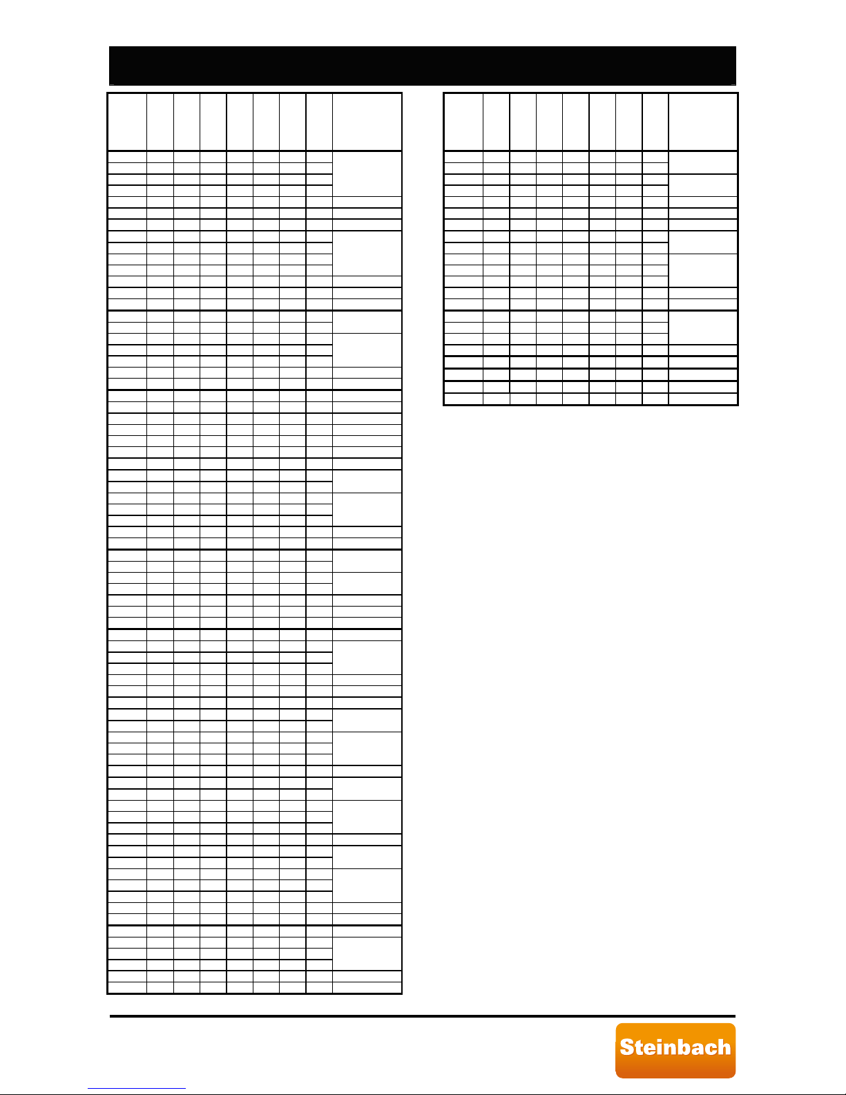
Speedheat Waterpower page 31 of 44
IRUWRGD\µVOLIHVW\OH
#
BP-35WS-B
BP-35HS-A
BP-50WS-B
BP-50HS-A
BP-85HS-A
BP-100HS-A
BP-160HS-A
29 X
32 X
29 X
33 X
XW50HSI033A
32 X XW85HSI033A
32 X XW100HSI033A
33 X XW160HSI033A
30 X
33 X
34 X
30 X
XW50HSI034A
33 X XW85HSI034A
33 X X XW100HSI034A
34 X XW160HSI034A
31 X
34 X
XW35HSI035A
35 X
31 X
34 X
XW50HSI035A
34 X XW100HSI035A
38 X XW160HSI035A
32 X XW35WSI036A
35 X 32 X XW50WSI036A
36 X XW50HSI036A
35 X XW85HSI036A
35 X XW100HSI036A
39 X XW160HSI036A
33 X
36 X
XW35HSI037A
37 X
33 X
36 X
XW50HSI037A
36 X XW100HSI037A
40 X XW160HSI037A
34 X
37 X
XW35HSI038A
38 X
34 X
XW50HSI038A
37 X XW85HSI038A
37 X XW100HSI038A
41 X XW160HSI038A
35 X XW50WSI039A
38 X
35 X
39 X
XW50HSI039A
38 X XW85HSI039A
38 X XW100HSI039A
42 X XW160HSI039A
36 X
39 X
XW35HSI040A
40 X
38 X
39 X
XW50HSI040A
39 X XW100HSI040A
37 X
40 X
XW35HSI041A
41 X
37 X
41 X
XW50HSI041A
40 X XW100HSI041A
41 X
38 X
XW35HSI042A
42 X
38 X
41 X
XW50HSI042A
41 X XW100HSI042A
43 X XW160HSI042A
42 X X XW35HSI043A
43 X
39 X
42 X
XW50HSI043A
42 X XW100HSI043A
44 X XW160HSI043A
#
BP-35WS-B
BP-35HS-A
BP-50WS-B
BP-50HS-A
BP-85HS-A
BP-100HS-A
BP-160HS-A
43 X
40 X
XW35HSI044A
44 X
40 X
XW50HSI044A
43 X XW85HSI044A
43 X XW100HSI044A
45 X XW160HSI044A
41 X
44 X
XW35HSI045A
45 X
41 X
44 X
XW50HSI045A
44 X XW100HSI045A
46 X XW160HSI045A
46 X
42 X X
45 X X X
XW50HSI046A
20 X XW160HSI046A
13 X XW160HSI048A
35 X XW160HSI049A
36 X XW160HSI050A
37 X XW160HSI051A
Page 32
Speedheat Waterpower page 32 of 44
IRUWRGD\µVOLIHVW\OH
speedheat
Waterpower 5000
speedheat
Art.Nr.: 00-49200 / BP-50HS-A
speedheat
Waterpower 8500
speedheat
Art.Nr.: 00-49205 / BP-85HS-A
 Loading...