

Page 1
11.TECHNICAL FEATURES
Output power RMS
4 Ohms
-
@
-
@
Inputs
Input sensitivity
Outputs
Output voltage RCA / Cinch
Frequency response
DSP resolution
DSP power
Sampling rate
Signal converters
Signal-to-noise ratio digital input
Signal-to-noise ratio analog input
Distortion(THD)
Damping factor
Input impedance RCA
Input impedance highlevel
Operating voltage
Additional features
Dimensions ( W x D x H)
.................................................................
.................................................................
2 Ohms
..........................................................................
............................................................
.......................................................................
.........................................
...................................................
.............................................................
..................................................................
..............................................................
........................................................
.................................
................................
...........................................................
...........................................................
.................................................
...........................................
........................................................
......................................................
..............................................
65 Watts per channel (< 1% THD+N)
90 Watts per channel (< 1% THD+N)
2 x RCA / AUX in
6 Highlevel speaker input
1 x Optical SPDIF (12 - 96 kHz)
1 x Remote In
RCA / Cinch 400mv 1 x COAX in
Highlevel 5 - 10 Volts or 10 - 20 Volts
6 x Speaker
2 x RCA / Cinch
1 x Remote Out
> 5 Volts RMS
20 Hz - 22,000 Hz
32 Bit
295 MHz (1.2 billion MAC operations/second)
48 kHz
A/D: Transformation mode
D/A: Transformation mode
105 dB (A-weighted)
100 dB (A-weighted)
< 0.015 %
> 70
22 kOhms
200 Ohms
9 - 15 Volts (max. 5 sec. down to 6 Volts)
Control Input, USB, HEC slot
250 x 210 x 57.5 mm / 11.06 x 8.26 x 2.34”
,
Ower s Manual
Digital Signal Processor
D04-MEN082-00
SDSP 6
DIGITAL SIGNAL PROCESSOR
Page 2
PRODUCT BRIEF INTRODUCTION
PRODUCT BRIEF INTRODUCTION
INDEX
1. PRODUCT DESCRIPTION-PRECAUTIONARY NOTES............................02
2. PACKAGING CONTENTS........................................................................02
3. DSP AND DRC INSTALLATION...............................................................03
4. CONNECTION PANELS-DESCRIPTION..................................................04
4.1 Input signals ............................................................................................04
4.2 Output signals ..........................................................................................05
4.3 Input -remote control outputs and power supply..........................................05
5. CONNECTIONS.......................................................................................06
5.1 Power supply and remote turn on ..............................................................06
5.2 Personal computer and Digital Remote Coontrol(DRC) ..............................07
5.3 High-Level input signals ............................................................................07
5.4 Low-Level input signals ............................................................................08
5.5 Bluetooth Low-Level input signals .............................................................08
6. SOFTWARE INSTALLATION....................................................................09
6.1 DSP GUI installation ............................................................................09-10
7. GUI OPERATION INSTRUCTION.............................................................11
7.1 Guide to GUI after installation ...................................................................11
7.2 Interface introduction .........................................................................12-16
8. STAND INSTALLATION REFERENCE......................................................16
8.1 5 channel stand alone treble mode ............................................................16
8.2 3 way crossover treble mode......................................................................17
9. REMOTE INTRODUCTION.......................................................................17
10. APP INTRODUCTION.............................................................................18
11. TECHNICAL FEATURES.........................................................................19
1.PRODUCT DESCRIPTION-PRECAUTIONARY NOTES
The DSP is a digital signal processor essential to maximize the acoustic performance of your car audio system.
It consists of a 32-bit DSP processor and 24-bit AD and DA converters.
It can connect to any factory system,even in vehicles featuring featuring an intergrated audio processor,since,thanks to the.
De-equalization function,the DSP will send back a linear signal.
It features selectable High and low level inputs as well as 3.5MM Aux and digital inputs that feed 8 completely variable output
channels. Each output channel has a 31-band equalizer available.it also features a 66-freqency electronic crossover as well as .
BUTTERWORTH or LINKWITZ filters with 6-24dB slopes and a digital time delay line.the user canselect adjustments.
That allow him or her to interact with the DSP through a remote control device called DRC.
WARNING: 1-a PC provided with Windows XP,Windows Vista or Windows 7 operating system,1.5GHz minimum.
Processor speed ,1 GB RAM minimum memory and a graphics card with a minimum resolution.
Of 1024x600 pixels are required to install the software and setup the DSP.
2-Before connecting you DSP, carefully read this manua .Improper connections may cause damage to
The DSP or to the speakers in the car audio system.
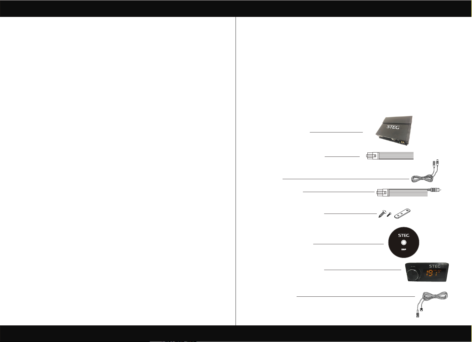
2.PACKAGING CONTENTS
- DSP- Signal Interface Processor
- Power supply cable Inputs/speaker output
- 5.0m USB cable
- Control High Level /wifi Input
[ 1 ]
- 4 of 4.0*15 mm/8of 3.0*6mm self-tapping,
C ross-head fixing screws,4 fixing brackets.
- CD ROM with:
DSP 1.0 software
This advanced manual(.pdf format)
Test tracks
OPTIONAL:
- DRC(Digital Remote Control)control panel:
- 5.0 m DRC-AC Link cable
[ 2 ]
DIGITAL SIGNAL PROCESSOR
GUI Installation software
Page 3
PRODUCT BRIEF INTRODUCTION
PRODUCT BRIEF INTRODUCTION
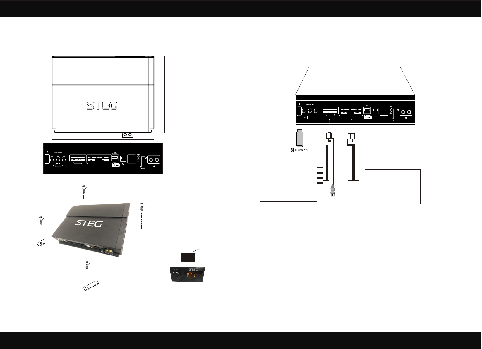
3.DSP AND DRC INSTALLATION
External dimensions
BLUETOOTHBLUETOOTH
SUB L/ R
MIN MAX
GAIN
MIN MAX
ACC ONACC ON AUTO ONAUTO ON
HIGH LEVEL INPUTHIGH LEVEL INPUT
RL/RR
FL/FR
GAIN
GAIN
MIN MAX
How to install
249mm
REM + SPEAKER OUT REM + SPEAKER OUT
SDSP 6
4.CONNECTION PANELS-DESCRIPTION
4.1 Input signals
210mm
11
BLUETOOTHBLUETOOTH
SUB L/ R
RL/RR
FL/FR
GAIN
GAIN
GAIN
MIN MAX
MIN MAX
MIN MAX
ACC ONACC ON AUTO ONAUTO ON
REMOTEREMOTE
OPTICALOPTICAL
CONTROL CONTROL
INPUT INPUT
GNDGND
FUSEFUSE
+12V+12V
57.5mm
HIGH LEVEL-INPUT
1.post RL +
2.post FR +
3.post RL +
4.post RR +
5.post SUB L +
6.post SUB R +
7.post COAX GND
8.post AUX L
9.post GND
10.post CH6 OUT
11.post FL -
12.post FR -
13.post RL -
14.post RR-
15.post SUB L -
16.post SUB R -
17.post COAX +
18.post AUX R
19.post GND
20.post CH5 OUT
20
HIGH LEVEL INPUTHIGH LEVEL INPUT
1
10
COAX-INPUT
REM + SPEAKER OUT REM + SPEAKER OUT
9 18
1
8
REMOTEREMOTE
OPTICALOPTICAL
CONTROL CONTROL
FUSEFUSE
INPUT INPUT
SDSP 6
+12V+12V
SPEAKER OUT+POWER INPUT
1.post CH1 OUT -
2.post CH2 OUT -
3.post CH3 OUT -
4.post CH4 OUT -
5.post CH5 OUT -
6.post CH6 OUT -
7.post
8.post
9. Post CH1 OUT +
10.post CH2 OUT +
11.post CH3 OUT +
12.post CH4 OUT +
13.post REM OUT
14.post REM IN
15.post CH7 OUT +
16.post CH8 OUT +
17.post
18.post
GNDGND
WARNING: do not use aggressive cleaning agents or abrasive cloth to clean the display.Simply use
a soft cotton colth lightly damped with water.
[ 3 ]
3M Glue
1. INPUTS;FR-FL-RR-RL,SUB R-SUB L inputs(SPEAKERS)
The DSP comes with 6 HI-LEVEL signal inputs to connect amplified signal cables coming
from the main Analog source.input sensitivity is adjusttable from 2 to 15V RMS.
Remark: if a low-level output source (PRE OUT)with output signal equal or greater than 2 V RMS
is available, you can Connect it to the high-level MASTER input(SPEAKERS).
Sensitivity is increased by adjusting the IN LEVEL controls.
[ 4 ]
Page 4

PRODUCT BRIEF INTRODUCTION
PRODUCT BRIEF INTRODUCTION
4.2 USB signals
BLUETOOTHBLUETOOTH
SUB L/ R
MIN MAX
GAIN
RL/RR
MIN MAX
ACC ONACC ON AUTO ONAUTO ON
HIGH LEVEL INPUTHIGH LEVEL INPUT
FL/FR
GAIN
GAIN
MIN MAX
REM + SPEAKER OUT REM + SPEAKER OUT
REMOTEREMOTE
OPTICALOPTICAL
CONTROL CONTROL
INPUT INPUT
SDSP 6
GNDGND
FUSEFUSE
+12V+12V
USB(type B)connection plug, to connect the processor to a PC and manage its funcitions
through the DSP 3 Software. The connection standard is USB 1.1/2.0 compatible.
4.3 Input - remote control outputs and power supply
SDSP 6
REMOTEREMOTE
OPTICALOPTICAL
CONTROL CONTROL
INPUT INPUT
GNDGND
FUSEFUSE
+12V+12V
BLUETOOTHBLUETOOTH
SUB L/ R
MIN MAX
GAIN
RL/RR
GAIN
MIN MAX
ACC ONACC ON AUTO ONAUTO ON
MIN MAX
HIGH LEVEL INPUTHIGH LEVEL INPUT
FL/FR
GAIN
REM + SPEAKER OUT REM + SPEAKER OUT
1. POWER SUPPLY.
+12V:Positive connection terminal for car 12V power supply.
GND:Power supply negative connection terminal(GND).
WARNING:make sure the connection polarity is as indicated on the terminals.A misconnection.
May result in damage to the DSP. After applying power,wait at least 10 seconds
Before turning the DSP on.
2. REMOTE IN-OUT.
REM IN:input to turn on the processor remotely along with the audio signal remote Out.
REM OUT:output to turn on other devices/amplifers connected after the processor.
From the REMOTE-IN signal, the processor only takes 1second to supply the signal to the
REM OUT output. The 130-mA output current capability can also drive an automotive relay
(Making sure it does not exceed 130 mA).
5.CONNECTIONS
5.1 Power supply and remote turn on
WARNING: to power the device,use 1 mm (16 AWG) cables.
BLUETOOTHBLUETOOTH
SUB L/ R
RL/RR
FL/FR
GAIN
GAIN
GAIN
MIN MAX
MIN MAX
MIN MAX
ACC ONACC ON AUTO ONAUTO ON
REMOTE OUT
Fuse Holder
Not Provided
12V
Suggested Fuse
+
T30A-delayed
Ground
Remark: the DSP is intermally protected by a
Fuse-resistor soldered on its printed circuit board
To replace it contact a service center. Using an
External fuse is recommended, though it is not required.
2
HIGH LEVEL INPUTHIGH LEVEL INPUT
REM + SPEAKER OUT REM + SPEAKER OUT
+ BATT +12V
16 AWG
SDSP 6
REMOTEREMOTE
OPTICALOPTICAL
CONTROL CONTROL
INPUT INPUT
GNDGND
FUSEFUSE
+12V+12V
-BATT
Ground
[ 5 ]
[ 6 ]
Page 5

PRODUCT BRIEF INTRODUCTION
PRODUCT BRIEF INTRODUCTION
5.2 Personal computer and Digital Remote Coontrol(DRC)
BLUETOOTHBLUETOOTH
SUB L/ R
MIN MAX
GAIN
RL/RR
GAIN
MIN MAX
ACC ONACC ON AUTO ONAUTO ON
FL/FR
GAIN
MIN MAX
HIGH LEVEL INPUTHIGH LEVEL INPUT
REM + SPEAKER OUT REM + SPEAKER OUT
SDSP 6
OPTICALOPTICAL
REMOTEREMOTE
CONTROL CONTROL
INPUT INPUT
FUSEFUSE
5.3 High-Level input signals
1.SPEAKERS IN HI-LEVEL STEREO FRONT+REAR+SUBWOOFER .
5.5 Output signals
Output to an amplifier is system .
GNDGND
+12V+12V
BLUETOOTHBLUETOOTH
SUB L/ R
GAIN
MIN MAX
RL/RR
GAIN
MIN MAX
ACC ONACC ON AUTO ONAUTO ON
FL/FR
GAIN
MIN MAX
HIGH LEVEL INPUTHIGH LEVEL INPUT
REM + SPEAKER OUT REM + SPEAKER OUT
SDSP 6
OPTICALOPTICAL
INPUT INPUT
REMOTEREMOTE
CONTROL CONTROL
FUSEFUSE
GNDGND
+12V+12V
5.5 Low-Level ,BLUETOOCH input signals
BLUETOOTHBLUETOOTH
FL/FR
GAIN
MIN MAX
HIGH LEVEL INPUTHIGH LEVEL INPUT
SUB L/ R
MIN MAX
GAIN
RL/RR
GAIN
MIN MAX
ACC ONACC ON AUTO ONAUTO ON
AMPLIFIED RADIO DECK
REM + SPEAKER OUT REM + SPEAKER OUT
SDSP 6
[ 7 ]
OPTICALOPTICAL
REMOTEREMOTE
CONTROL CONTROL
INPUT INPUT
GNDGND
FUSEFUSE
+12V+12V
AUX IN L/R: Auxiliary analog stereo sigal .
Sensitivity is adjusttable from 0.6 to 5V RMS .
BLUETOOTHBLUETOOTH
SUB L/ R
RL/RR
GAIN
GAIN
MIN MAX
MIN MAX
ACC ONACC ON AUTO ONAUTO ON
BlueTooth IN :
Insert the Bluetooth control module into the DSP .
turn on your mobile phone and find the Bluetooth control mode.
Click on the Bluetooth . When the control mode is automatically
Paired successful . Then you can play the music.
DO NOT INSERT THE USB.
FL/FR
GAIN
MIN MAX
HIGH LEVEL INPUTHIGH LEVEL INPUT
REM + SPEAKER OUT REM + SPEAKER OUT
SDSP 6
OPTICALOPTICAL
INPUT INPUT
REMOTEREMOTE
CONTROL CONTROL
FUSEFUSE
GNDGND
+12V+12V
[ 8 ]
Page 6

PRODUCT BRIEF INTRODUCTION
PRODUCT BRIEF INTRODUCTION
6.SOFTWARE INSTALLATION
6.1 DSP GUI installation
1.Insert CD, Double-Click DSP
2.Wait until the process finish
6.Wait until the process finish 7.Click finish
3.Click NEXT
7.GUI OPERATION INSTRUCTION
7.1 Guide to GUI after installation
1. Double - click icon of DSP-CONTROL
4.Click NEXT
5. Set install location
[ 9 ]
STEG DSP
v1.0.0
2. DSP connection
[ 10 ]
Page 7

PRODUCT BRIEF INTRODUCTION
PRODUCT BRIEF INTRODUCTION
3. Enter the GUI you long for! Now you could tone every signal details as experts do
To bring sound effect on your beloved car to a higher level.If the password has been set,
You need to enter the password.
7.2 Interface introduction
1.DSP interface guidance
2. FILE MAIN MENU
1. Connect(connect to the DSP)
2. Language(choose you need language)
3. Open(To load preset file in PC folder)
4. Save(To save setting to PC)
5. Save as(To save another file setting to PC)
6. Modify Password
7. Restore Factory(To save preset file in DSP)
8. Update Firmware (To load preset file in DSP)
9. About
10. Exit
1
1
2
3
4
5
6
7
8
9
10
[ 11 ]
3. INPUT MODE.
To select different input devices.
2. CHANNAL SETING.
1
OPTIONAL FULLRANGE. 2 WAY CROSSOVER. 3 WAY CROSSOVER. CLEAR ALL.
To select different colour devices.
[ 12 ]
Page 8

PRODUCT BRIEF INTRODUCTION
CH mode(click on the default in put state).
2
optional (2CH 4CH 6CH MIX).
Input channel:FL. FR. FL. FR. RL. RR. SUB L. SUB R.
3
When you click the drop-down button, you can choose the stste of the channel input.
There is : FR. FL. RR. RL. SUB R. SUBL.M1=FL+FR.M2=FL+RL.M3=FR+RR.
M4=FL+RL+SUBL.M5=FR+RR+FUBR.
Output channel:FL FullRange.FR FullRange.RL FullRange.RR FullRange.L FullRange
4
R FullRange
When you click the drop-down button, you can choose the stste of the channel input.
There is : Front.Rear.Center.Subwoofer and Full.Tweeter.Mid-Hi.Midrange.Midbass Woofer
PRODUCT BRIEF INTRODUCTION
4. CROSSOVER X-TPE.
To choose different crossover type, for example select CH selection on 3RD
spot .that would locate CH you want to choose for crossover configuration .
5. CROSSOVER FREQUENCY.
Set frequency of LP/HP individually .
6. GAIN.
0--40dB is optional range for gain control kf every CH.
7. DELAY.
1.Auto configuration(base on 1.5 setting).
2.Manual configuration, change specifications in selected CH manually.
6
7
Options on the Link are for combine setting for Left CH and Right CH .
Options on the Left CH/right CH allow you tone each selected channel respectively.
[ 13 ]
8. LP/SLOPE.
1.6dB/oct 12dB/oct 18dB/oct 24dB/oct 30dB/oct 36dB/oct.
42dB/oct 48dB/oct are available.
[ 14 ]
Page 9

PRODUCT BRIEF INTRODUCTION
PRODUCT BRIEF INTRODUCTION
9. HP/SLOPE.
1.6dB/oct 12dB/oct 18dB/oct 24dB/oct 30dB/oct 36dB/oct.
42dB/oct 48dB/oct are available.
10. Filter Model.
To choose different Filter type Linkwitz Bessel Butterworth.
11. WRITE.
To save setting to DSP(POS1-POS8).
12. READ.
To read setting from DSP(POS1-POS8).
1
12. X-OVER AND EQ CHARTS.
1.Red lines and slopes will change accordingly when
HP/LP of crossover and EQ are modified.
2 .EQ all frequency points can be move left or right.For 20Hz-20KHz can be any Regulation.
13. EQ SETTING.
Q volue=1-12.
8.STAND INSTALLATION REFERENCE
8.1 5 CHANNEL STAND ALONE TREBLE MODE
To delete setting from DSP(POS1-POS8).
2
[ 15 ]
GroundGround
SubwooferSubwoofer
[ 16 ]
Page 10

PRODUCT BRIEF INTRODUCTION
PRODUCT BRIEF INTRODUCTION
8.2 3 WAY CROSSOVER TREBLE MODE
GroundGround
Subwoofer/CH7+CH8 To SubwooferSubwoofer/CH7+CH8 To Subwoofer
9.REMOTE INTRODUCTION
10.PHONE APP INTRODUCTION
10.1 Download DSP APP and install it on your phone
PM 2:20
APP Source: CD
Version: 1.0.0
Authority Particulars
Cancel
SDSP
Install
PM 2:20
Click install
PM 2:20
INPUT SETUPS
AUX
SPDIF
1
MAIN BT
COAX
2
Authority Particulars
Finish
Click open
SDSP
Open
5
6
7
1
2 3 4
1. A.Main volume.
B.When you press this button for a short time,It is in the MUTE state. And theclose MUTE .
C.When you press this button for a longer time(for a second) ,It will enter the menu mode .
In the MODE or INPUT flishing. You can adjust the mode which you want.
2.Main volume display window.
3.DSP mode display window(1-8).
4.Input display status.(CD.AUX.SPDIF.WIFI).
[ 17 ]
3
4
MODE SETUPS
1. Input Mode
To select different input devices MAIN.AUX.SPDIF.COAX.BLUETOOTH.
2. Dsp Main volume display.
3. Dsp Main volume control.
4. MODE SETUPS (1-8POS) .
5. Click on the Bluetooth.when the control mode is automatically paired successful.
Then you can play the APP .
6. Dsp subwoofer volume display.
7. Speaker mute control.
Remark: APP can not be joined to DSP when the computer is connected to DSP
[ 18 ]
 Loading...