


V18
"MANUFACTURED IN NORTH AMERICA"
OWNER'S AND
INSTALLER'S MANUAL
for
COMFORT PLUS
Forced Air Heating Systems
Equipped with Variable Speed
3100 Series
4100 Series
Models: 3120, 4120, 4130, & 4140
Applicable to Software Version 2.00-2.19
This manual applies to heating |
U.S. Pat. #5201024, |
#5086493 |
systems built after 01/01/2011. |
Can. Pat. #2059158, |
#2060881 |

 IMPORTANT
ωThe equipment described herein is intended for installation by a qualified technician in compliance with applicable local, state, and national codes and requirements.
ωTo insure proper installation and operation of this product, completely read all instructions prior to attempting to assemble, install, operate, maintain or repair this product. Upon unpacking of the system, inspect all parts for damage prior to installation and start-up.
ωThis manual should be retained by the owner upon completion of the installation and made available to service personnel as required.
ωDisclaimer: In compiling this manual, Steffes Corporation has used its best judgement based upon information available, but disclaims any responsibility or liability for any errors or miscalculations contained herein, or any revisions hereof, or which result, in whole or in part, from the use of this manual or any revisions hereof.
Steffes disclaims any responsibility or liability for mold/mildew growth and/or any damages caused by either which occur after the heating system is installed. We strongly recommend that the user follow the moisture, mold and mildew prevention guidelines of the Environmental Protection Agency (EPA), available at http://www.epa.gov. If you are unable to find information and have concerns, contact Steffes Corporation.
For Customer Use
Please record your model and serial number below. This number is found on the identification label located on the lower front of the 3100 series base and on the lower left side of the 4100 series base. Retain this information for future reference.
Model No. ________________________________________________________________________
Serial No. ________________________________________________________________________
RECOGNIZE THESE SYMBOLS AS SAFETY PRECAUTIONS
It is important, both for your personal safety and to avoid possible damage to the equipment and your property, that you observe the safety instructions given following these symbols.
SAFETY PRECAUTIONS
1.Install all ceramic brick and completely assemble the heating system before energizing the system to avoid damage to the heating system.
2.DO NOT use or store materials that may produce explosive or flammable gases near this heating system.
3.Maintain all placement and clearance requirements as specified in this manual to ensure proper operation and safety.
4.Keep the top of the heating system free of debris and other objects.
5.Disconnect power to all circuits before servicing. This heating system may be connected to more than one branch circuit.
6.Installation of and/or service to this heating system should be performed by a qualified technician in compliance with information contained herein and with national, state, and local codes and requirements.
7.A repeated message of “CORE FAIL” indicates a need for service by a qualified technician.
 WARNING
Hazardous Voltage: Risk of electric shock. Can cause injury or death. This heater may be connected to more than one branch circuit. Disconnect power to all circuits before installing or servicing. Installation of and/or service to this equipment MUST be performed by a qualified technician.
Risk of fire. Can cause injury or death. Violation of the clearance requirements can cause improper operation of the equipment. Maintain the placement and clearance requirements specified.
BUILT-IN SAFETY DEVICES
The Comfort Plus heating system incorporates safety devices to ensure normal operating temperatures are maintained. The chart below describes these safety devices.
DEVICE NAME |
FUNCTION |
LOCATION |
|
ON SYSTEM |
|||
|
|
||
|
|
|
|
Core Charging High |
These limit switches monitor brick core charging and |
In the limit bar panel |
|
Limit Switches |
interrupt power to the heating elements if the normal |
on the left side of the |
|
(Auto Reset) |
operating temperature is exceeded. |
brick storage cavity. |
|
|
|
|
|
Core Blower |
This limit switch monitors the discharge air temperature |
3100: In the discharge |
|
Limit Switch |
and interrupts power to the core blower(s) if the normal |
air supply outlet. |
|
(Auto Reset) |
operating temperature is exceeded: |
4100: On the supply |
|
|
3100 Series = 130oF (nominal) |
air blower |
|
|
4100 Series = 160oF (nominal) |
assembly. |
|
|
|
|
|
Supply Air Blower |
This limit switch monitors the discharge air temperature |
3100: In the discharge |
|
Limit Switch |
|||
and interrupts power to both the supply air blower and the |
air supply outlet. |
||
|
|||
|
core blower(s) if the normal operating temperature is |
4100: On the supply |
|
|
exceeded: |
air blower |
|
|
3100 Series = 160oF (nominal) Auto Reset |
assembly |
|
|
4100 Series = 190oF (nominal) Manual Reset |
|
|
Base Temperature |
This limit switch monitors the temperature in the base of the |
In the base of the |
|
Limit Switch |
Comfort Plus and interrupts power to the core blower(s) if |
system near the core |
|
(Auto Reset) |
the normal operating temperature is exceeded. |
blower(s). |
|
|
|
|
Comfort Plus |
Safety Information |

TCTable of Contents
Operation
General Operation ........................................................................................................................................................................ |
1.01 |
System Use During Construction Phase ...................................................................................................................................... |
1.01 |
System Start-Up ........................................................................................................................................................................... |
1.01 |
Turning System "OFF" and "ON" ............................................................................................................................................... |
1.01 |
Control Panel ............................................................................................................................................................................... |
1.02 |
Operating Status .......................................................................................................................................................................... |
1.02 |
Room Temperature Control .......................................................................................................................................................... |
1.03 |
Brick Core Charge Control ........................................................................................................................................................... |
1.03 |
Charge Control Override .............................................................................................................................................................. |
1.03 |
Maintenance and Cleaning .......................................................................................................................................................... |
1.03 |
Optional Accessories
Single Electrical Feed Kit ............................................................................................................................................................. |
2.01 |
Comfort Plus Stand - 4100 Series ................................................................................................................................................. |
2.01 |
Down Flow Kit ............................................................................................................................................................................. |
2.01 |
Return Air Plenum - 4100 Series ................................................................................................................................................... |
2.01 |
Installation
Shipping and Packaging .............................................................................................................................................................. |
3.01 |
Placement and Clearance Requirements ................................................................................................................................ |
3.02-3.03 |
Initial Set-up .......................................................................................................................................................................... |
3.03-3.04 |
Brick Loading ............................................................................................................................................................................... |
3.04 |
Heating Element and Air Channel Installation ............................................................................................................................. |
3.05 |
Brick Core Temperature Sensor Installation - 4100 Series Only ................................................................................................... |
3.06 |
Ducting ................................................................................................................................................................................. |
3.06-3.07 |
Air Conditioner/Heat Pump Interface ........................................................................................................................................... |
3.08 |
Line Voltage Electrical Connections ..................................................................................................................................... |
3.08-3.09 |
Low Voltage Electrical Connections |
|
Peak Control .................................................................................................................................................................. |
3.09-3.10 |
Outdoor Temperature Sensor ............................................................................................................................................... |
3.10 |
Room Thermostat .......................................................................................................................................................... |
3.11-3.12 |
Auxiliary Load Control ................................................................................................................................................................. |
3.12 |
Humidifier/Electronic Filter Installation ........................................................................................................................................ |
3.12 |
Configuration Menu ............................................................................................................................................................. |
3.13-3.14 |
Installer's Final Check-Out Procedure.......................................................................................................................................... |
3.15 |
Appendix
Specifications .............................................................................................................................................................................. |
A.01 |
Disassembling the 4100 Series Comfort Plus System .................................................................................................................. |
A.02 |
Parts Diagram - 3100 Series ......................................................................................................................................................... |
A.03 |
Parts List - 3100 Series ....................................................................................................................................................... |
A.04-A.05 |
Parts Diagram - 4100 Series ......................................................................................................................................................... |
A.06 |
Parts List - 4100 Series ....................................................................................................................................................... |
A.07-A.08 |
Internal System Wiring Diagrams - Line Voltage ............................................................................................................... |
A.09-A.12 |
Internal System Wiring Diagram - Low Voltage .......................................................................................................................... |
A.13 |
Help Menu .................................................................................................................................................................................. |
A.14 |
Error Codes ........................................................................................................................................................................ |
A.14-A.15 |
Glossary ...................................................................................................................................................................................... |
A.16 |
Warranty
Table of Contents |
Comfort Plus |

1 Operation
GENERAL OPERATION
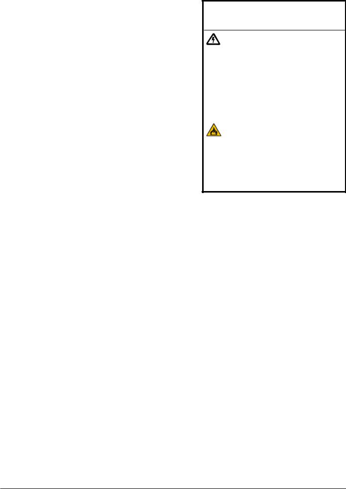
The Steffes Comfort Plus heating system stores off-peak electricity in the form of heat. Off-peak electricity is available during times of day or night when electricity is plentiful and the power company can supply it at a lower cost.
Operation of the Comfort Plus heating system is automatic. When off-peak hours are available, the system converts electricity to heat which is then stored in its ceramic brick core. The amount of heat stored in the brick core varies in relation to outdoor temperature, owner preference, utility peak conditions, and the heating requirements.
 Operation
A heat call from the room thermostat energizes the blowers in the Comfort Plus system. The variable speed core blower(s) automatically adjust its speed to circulate room air through the brick core. The supply air blower then delivers this heated air into the desired area through the duct system to maintain a constant, comfortable room temperature.
The versatility of this system allows it to fit many applications. The Comfort Plus is designed for use as either the sole heating source (“stand alone” furnace) or as a supplement to ducted heating systems such as heat pumps.
SYSTEM USE DURING CONSTRUCTION PHASE
Like most heating equipment manufacturers, Steffes strongly recommends that “Construction Heating Units” be used instead of the permanent heating system during the construction phase of a new home. Use of the permanent heating system during this phase may contaminate the duct system and/or internal areas of the heating system. This may cause poor indoor air quality issues, systems reliability problems, and/or improper system operation once the home is completed.
SYSTEM START-UP
On start-up of the Comfort Plus system, odors relating to first time operation of the heating components may be experienced. Also, if not used for an extended period of time, dust may accumulate in the system. Allow the Comfort Plus heating system to charge to its maximum brick core charge level to expel odors in a timely manner.
As with most heating systems, air borne particles and odors in the room may be drawn into the Comfort Plus and oxidized. Odors can be amplified; thus, it is not recommended to operate the system if odors such as those from paints, varnishes, or chemicals are present in the air. Air borne particles, which have been oxidized, are expelled back into the room and may accumulate on air vents or other surfaces. Over time, these particles may appear as a black residue, commonly referred to as soot. High concentrations of air borne particles from aerosols, dust, candles, incense, pet hair, smoke, or cooking can contribute to poor indoor air quality and accelerate the sooting process.
During operation, the Comfort Plus heating system may produce minor expansion noises. These noises are the result of the internal components reacting to temperature changes.
TURNING SYSTEM "OFF" AND "ON"
The Comfort Plus element (charging) circuits may be turned “OFF” by switching ALL of the 60 AMP breakers located on the front of the electrical panel to the DOWN position. To turn the element circuits “ON”, switch ALL of the 60 AMP breakers to the UP position.
The 15 AMP breaker MUST remain “ON” to operate controls in the system if:
ωusing the Comfort Plus in conjunction with a heat pump or air conditioner.
ωusing the Comfort Plus to control other loads.
ωusing the optional Steffes Time Clock Module.
Comfort Plus |
Operation ν 1.01 |

Operation
CONTROL PANEL
Operation of the Comfort Plus heating system is automatic. Operational function settings are stored in a microprocessor on the processor control board. These settings are modified, if necessary, through the Configuration Menu as described on Pages 3.13-3.14. In most applications, the system is configured upon installation and no further changes are required.
Four-Digit LED Display
The four digit LED displays specific operating information. During the configuration process, the configuration number and the values set in these configurations are displayed for viewing and adjusting purposes.
AM and PM Indicator Lights
A
M 
P
M

 M
M

CONTROL PANEL
FIGURE 1
The AM and PM indicator lights are only utilized if the Steffes Time Clock Module is being installed and using 12 hour time display. With this module installed, the system displays time on AM/PM intervals. The light flashes next to the active designator/symbol. The system can be configured to display military time, in which case, both the AM and PM lights illuminate.
M Mode (Edit) Button
Used to access menus on the system (i.e. Help Menu or Configuration Menu) and to allow modifying of configuration settings.
Up and ∫ Down Arrow Buttons
Used to scroll up or down when viewing or modifying. operating functions.
 Interface Port
IMPORTANT
Editing configuration information may alter the performance and operation of the system.
Allows technician external access for advanced operating modes, updating software, and troubleshooting.
OPERATING STATUS
The four digit LED will display various operating information as described below. Press and release the up arrow to view this data.
Operating Mode - Indicates the current operating mode of the Comfort Plus system. C = Off-Peak (Charge) Time
P = On-Peak (Control) Time
A = Anticipated Peak Time
Outdoor Temperature -“O”, followed by a number, indicates current outdoor temperature.
Heat Call Status - Indicates the current heat call status being received from the room thermostat. Refer to Low Voltage Electrical Connections - Room Thermostat for more information.
Brick Core Charge Level - “CL” (charge level) followed by a number, indicates the current percentage of heat stored in the brick core. “CL:_” represents a core temperature lower than the minimum core temperature and “CL: F” represents a full core charge level.
Targeted Brick Core Charge Level - “tL” (target level) followed by a number, indicates the current percentage of brick core charge being targeted by the Comfort Plus. A display of “tL:_” indicates that the system will not maintain any heat in the brick core and “tL: F” indicates a full core charge target level.
Operation ν 1.02 |
Comfort Plus |

ROOM TEMPERATURE CONTROL
The room temperature set point is adjusted at the wall thermostat. If room temperature drops below the thermostat set point, the thermostat initiates a heat call and energizes the blowers in the Comfort Plus heating system. The variable speed core blower(s) automatically adjust speed in relation to brick core temperature and duct temperature to circulate room air through the brick core. The supply air blower then delivers the heated air into the living area through the duct system to satisfy heating requirements. When the thermostat senses a demand greater than the output, another stage of heating is initiated.
When used to supplement heat pump systems, the Comfort Plus replaces the resistance strip heat, which is typically required as a supplement or back-up to the heat pump system. A duct sensor monitors the discharge air temperature. If the demand for heat is at a point where the heat pump alone cannot maintain the desired duct temperature, stored heat is used to supplement the heat pump and satisfy the heating requirements.
BRICK CORE CHARGE CONTROL
The amount of heat stored in the brick core of the Comfort Plus system is regulated automatically in relation to outdoor temperature and the heating requirements. The outdoor sensor, supplied with the system, monitors outdoor temperature and provides this information to the Comfort Plus. As the outdoor temperature decreases, heating requirements increase and the system stores more heat accordingly.
CHARGE CONTROL OVERRIDE
The Comfort Plus is equipped with a charge control override feature that allows the user to force the system to target a full core charge level. This override can be initiated or cancelled at any time. If an override is initiated, the system targets a full core charge level during the next off-peak period. It continues to charge during off-peak hours until the system achieves full (maximum) core charge or until the override is cancelled. Once full charge is achieved or the override is cancelled, the system charges according to the standard configuration.
Initiating the Override Feature
Step 1 Press and hold the M, the up arrow, and the down arrow buttons at the same time.
Step 2 The faceplate will flash “FULL” and “ON”. Continue to hold all three buttons until “ON” displays continuously.
Step 3 Release the buttons. The override is now enabled. The faceplate will return to displaying its standard operating mode.
Manual Cancellation of the Override Feature
Step 1 Press and hold the M, the up arrow, and the down arrow buttons at the same time.
Step 2 The faceplate will flash “FULL” and “OFF”. Continue to hold all three buttons until “OFF” displays continuously.
Step 3 Release the buttons. The override is now cancelled. The faceplate will return to displaying its standard operating mode.
•This feature will not turn elements on during a peak period.
•This feature will cancel if power is interrupted.
MAINTENANCE AND CLEANING
The Comfort Plus heating system is easily maintained. The air filter in the return air duct of the system should be replaced on a regular basis to ensure proper operation and to maintain overall efficiencies. No additional routine maintenance is required.
If utilizing a heat pump or air conditioning system with the Comfort Plus, the indoor coil of the device should be cleaned periodically as dirt accumulation may reduce system efficiency. It is important to follow the
manufacturer’s maintenance and cleaning recommendations for these devices.
Operation
Comfort Plus |
Operation ν 1.03 |
2
SINGLE ELECTRICAL FEED KIT
The Steffes Comfort Plus systems have built-in circuit breakers. They are factory configured to be field connected to multiple line voltage circuits. If single feed to the element and blowers/control circuits is desired, the single feed kit is available to allow the system to be powered with a one, larger line voltage circuit.
Model |
Part # |
3120 |
1301574 |
4120 |
1301572 |
4130/4140 |
1301570 |
Accessories
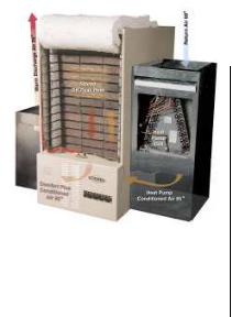
COMFORT PLUS STAND - 4100 SERIES
Some applications (such as garages) may require that the heating appliance be elevated in order to meet building codes. The Steffes Comfort Plus stand elevates the 4100 system 18". This stand is shipped as a kit and requires field assembly.
Stand
Order Item #1301585
DOWN FLOW KIT |
RETURN AIR PLENUM - 4100 SERIES |
|
Order Item #1301578 |
Order Item #1301550 |
|
|
|
|
|
|
|
26 1/16”
52 5/16”
Duct 

 Opening (connects
to unit)
9.263
+ Set Height
of Leveling Legs.
22 3/16”
Filter Tray
(Fits 20" x 25" x 2" filters, one included)

 Heating/Cooling A-Coil Tray
Inner Dimensions: 26"W x 22"D x 31" H
Front Access: 2521 "W x 22"D x 30"H
28 3/16”
Optional Accessories ν 2.01 |
Comfort Plus |

3 Installation
CAUTION Risk of sharp edges. Can cause personal injury. Use caution when installing and/or servicing equipment.
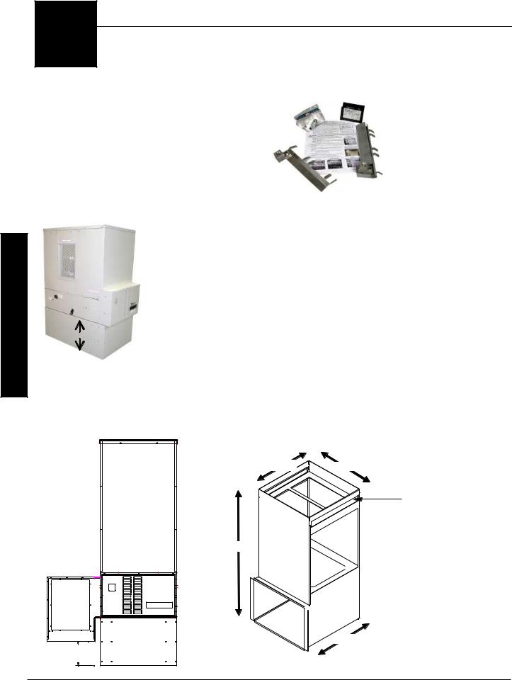
SHIPPING AND PACKAGING
The Comfort Plus system should always be transported in an upright position to avoid damage to internal components and insulation materials. The information below describes the items shipped with each system.
1 INFORMATION PACKAGE
(includes Owner's Manual and
Warranty Registration Card)
(adhered to outer side of shipping box)
2 ELEMENT SCREW KIT
(shipped inside the electrical compartment)
3CERAMIC BRICK
Full Brick
(shipped separately and packaged 4 brick per box)
|
Half Brick |
||
|
(shipped with brick and |
||
|
packaged in a white box |
||
|
consisting of 6 half brick |
||
|
and 1 full brick) |
||
|
|
|
|
MODEL |
FULLBRICK |
1/2 BRICK |
|
3120 |
18 Boxes |
0 Boxes |
|
4120 |
26 Boxes |
1Box |
|
4130 |
37 Boxes |
2 Boxes |
|
4140 |
49 Boxes |
2 Boxes |
|
|
|
|
|
4 HEATING ELEMENTS
MODEL |
ELEMENTS |
3120 |
8 |
4120 |
8 |
4130 |
12 |
4140 |
16 |
|
|
(shipped inside the base of the Comfort Plus)
5 OUTDOOR TEMPERATURE SENSOR
(shipped inside the electrical compartment)
6 SUPPLY AIR BLOWER ASSEMBLY
(4100 SERIES)
Packaging Dimensions 26 x 24.5 x 20.5
(shipped separately)
7 RETURN AIR PLENUM ASSEMBLY
(3100 SERIES)
Packaging Dimensions 27 x 40 x 4
(banded to the 3100 Series Comfort Plus for shipping)
Comfort Plus |
Installation ν 3.01 |
Installation
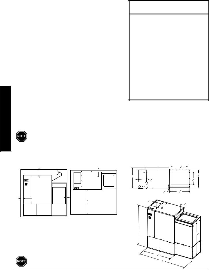
PLACEMENT AND CLEARANCE REQUIREMENTS
The physical dimensions of the Comfort Plus, along with the clearances required, MUST be taken into consideration when choosing its location within a structure. (See Figures 2 and 3 for system dimensions and clearance requirements.)
The best installation location for this system is in a space requiring heat so some amount of the heating requirements can be satisfied through static dissipation from the warm outer panels. In situations where the Comfort Plus is not installed in an area it is intended to heat (i.e. storage closet), it is important to account for the heat lost through static dissipation by making proper adjustments when sizing the system. Standby heat dissipation of up to 2.5kW can be experienced in normal operation. Room air should be maintained at less than 85° Fahrenheit.
If ventilation is needed, it can be provided by installing a 24” x 24” opening into the area where the Comfort Plus is located. In addition, a 6” x 6” non-closing type register can be cut into the return air duct of the furnace to minimize heat build-up in the room. This register must be installed in a manner that ensures the air drawn into the Comfort Plus passes through the filter first (see Figure 3A).
 WARNING
Risk of fire. Can cause injury or death.
ωViolation of the clearance requirements and/or failure to provide proper ventilation can cause improper operation of the system. Maintain the placement and clearance requirements as specified and provide ventilation as necessary.
ωFailure to maintain room temperature in the mechanical room of 85oF or less may result in equipment damage.
Thermostatically controlled ventilation should be provided if the temperature in this area exceeds 85oF.
ωMoving the system after install may result in equipment damage. Do NOT move system from original installed location.
In addition to the physical space requirements, the weight of the Comfort Plus must be taken into consideration when selecting the installation surface. A level concrete floor is the best installation surface on which to place the system, but most well supported surfaces are acceptable. If unsure of floor load capacity, consult a building contractor or architect.
Special requirements must be considered if placing the system in a garage or other area where combustible vapors may be present. Consult local, state, and national codes and regulations to ensure proper installation. An 18" pedestal (Order Item #1301585) is available to elevate the 4100 Series.
|
|
|
|
3100 SERIES SYSTEM REQUIREMENTS |
|
|
|
|
|
|||
|
|
|
|
|
FIGURE 2 |
|
DIMENSIONS |
|
|
|
|
|
|
|
|
CLEARANCES |
|
|
|
|
|
|
|||
|
|
|
|
|
|
|
|
22716" |
|
|
|
|
8" MIN CLEARANCE TO COMBUSTIBLES, |
|
1" |
Top View |
|
|
|
|
|
||||
0" MIN CLEARANCE TO DUCTING |
O" MIN |
|
|
|
225 |
16" |
||||||
|
|
|
|
CLEARANCE |
27" |
|
|
2C |
|
|
|
|
|
|
|
|
(BACK) |
1" |
81 |
" |
167 |
16 |
" |
|
|
15 |
60 |
60 |
|
TOP VIEW |
|
|
2 |
|
|
|
|
|
|
|
FRONT VIEW |
|
|
|
|
|
|
|
|
|
|
|
|
|
|
|
|
|
|
|
|
|
|
|
|
|
2A |
|
|
|
|
17 8" |
2618" |
|
|
|
|
|
|
0" MIN |
|
2 B |
|
|
|
|
|
|
|
|
|
|
4" MIN |
CLEARANCE |
|
|
|
|
|
|
|
|
|
|
|
TO RETURN |
|
|
|
|
|
|
|
|
||
|
|
CLEARANCE |
|
|
|
|
|
|
|
|
|
|
|
|
AIR DUCT |
|
|
10 18" |
|
|
|
|
|
|
|
|
|
|
36" MIN CLEARANCE (FRONT) |
|
|
|
|
|
|
|
||
|
|
|
|
|
|
|
16" |
5 3 |
8" |
|
|
|
ω Back and Bottom = 0 clearance |
60" |
2D |
|
ω Left Side = 4 inches |
|
Return |
|
|
Air |
|
|
ω Right Side = 8 inches (from combustible material) |
|
53 5 8" |
|
|
Plenum |
||
ω Top = 8 inches (from combustible material) |
|
(Factory |
|
|
Supplied) |
|
|
ω Front = 36 inches (for ease in servicing) |
|
|
|
ω Outer Sides of System Ducts (Return and Supply) = 0 clearance |
|
|
|
ω Between Ducting and System = 0 clearance (top and right side) |
|
41 5 8" |
|
Minimum clearance requirements may NOT account for |
|
67 716" |
|
required working space for electrical connections.
Installation ν 3.02 |
Comfort Plus |
4100 SERIES SYSTEM REQUIREMENTS
FIGURE 3
6" X 6" REGISTER
(IN COLD AIR RETURN)
|
|
6" MIN CLEARANCE |
|
|
2" MIN |
|
|
|
CLEARANCE |
|
|
FILTER TRAY |
|
|
|
48" |
FRONT VIEW |
|
|
0" REQUIRED |
3A |
0" REQUIRED |
|
CLEARANCE |
|||
CLEARANCE |
CLEARANCES |
3" MIN CLEARANCE |
TOP VIEW |
3 B |
36" MIN CLEARANCE |
ωBack and Sides = 3 inches (from combustible material)
ωBottom = 0 clearance
ωTop = 6 inches (from combustible material)
ωFront = 36 inches (for ease in servicing)
ωBetween Duct and Left Side of System = 2 inches
ωBetween Duct and Right Side of System = 0 clearance
ωOuter Sides of System Ducts (Return and Supply) = 0 clearance
Minimum clearance requirements may NOT account for required working space for electrical connections.
DIMENSIONS
|
|
4411" |
|
|
|
|
|
|
|
|
|
|
|
16 |
|
|
|
|
|
|
|
|
|
|
|
3C |
|
|
|
|
Electrical |
|
|
|
|
|
|
|
|
|
|
|
|
|
|
||
|
|
|
|
|
|
|
Panel |
|
|
|
|
|
|
|
|
|
|
101 |
|
|
|
|
|
4140 |
|
|
|
|
2 |
|
|
|
|
|
|
|
|
|
|
|
|
|
|
|
|
||
68 5 |
8" |
Front View |
8 3/8" |
|
|
|
5 |
|
|
|
|
|
|
|
|
|
2216 |
|
|
|
|
||
4130 |
(4100 Series) |
(± 1/4") |
|
|
|
|
|
|
|
|
|
|
|
|
|
|
|
|
|
|
|
||
57 5 |
8" |
|
|
|
|
|
|
|
|
|
|
4120 |
|
18" Standard |
|
|
|
|
|
|
|
||
|
|
1 |
|
|
|
|
|
|
|
||
46 5 |
8" |
|
22 |
2" if 1hp |
28 3 |
" |
|
24 43" if 1hp |
|
|
|
|
|
|
|
|
16 |
|
|
|
|
|
|
|
|
1 |
|
|
3 |
|
|
|
|
1 |
|
|
|
|
|
2616" |
|
|
|
204 |
|
||
|
|
244" |
|
|
|
|
|
|
|
|
|
|
|
1 |
|
|
|
|
3D |
|
|
|
|
|
|
2516" |
|
221" |
Return Air Plenum |
|
|
22 5/8" |
|||
|
|
|
|
|
Supply Air Plenum |
||||||
|
|
|
|
(Order Item |
|
|
|||||
|
|
|
|
|
|
(Factory Supplied) |
|||||
|
4916 |
|
4 |
#1301550) |
|
|
|
|
|
|
|
|
|
|
|
|
Top View |
|
|
|
|||
|
|
53 1615" if 1hp |
|
|
|
|
4100 Series |
|
|
|
|
|
|
|
|
14±1/4 |
|
3 |
± 1/4" |
|
|||
|
|
|
|
|
|
13 |
4 |
|
|||
|
|
|
|
|
|
|
|
|
|
|
|
|
|
|
|
|
|
|
29 |
3 |
|
|
|
|
|
|
|
|
|
|
16 |
|
|
|
|
IMPORTANT: Return air duct MUST NOT enter from the front or back of the furnace. Upflow, downflow, or straight return ducting only.
INITIAL SET-UP
Step 1 Remove the Information Package from the outside of the shipping box and unpackage the Comfort Plus heating system.
Step 2 Remove the heating elements from inside the base of the system.
Step 3 Move the system into its installation location. The Comfort Plus is capable of fitting through a 30" doorway (minimum) without disassembling. If necessary, the 4100 series can be disassembled for ease in moving. To disassemble the 4100 Series Comfort Plus, refer to the disassembly instructions (Page A.02) for more information.
IMPORTANT
Risk of improper operation or equipment damage. Read and follow installation instructions carefully.
ωRemove the Comfort Plus system from its shipping pallet before installing.
ωLeveling legs should be extended no more than one inch.
ωDO use and follow generally accepted safety practices when handling insulation material.
ωDO have equipment installed by a qualified technician in compliance with all applicable codes and regulations.
The 3100 series can NOT be disassembled.
Installation
Comfort Plus |
Installation ν 3.03 |
Step 4 Once in place, adjust the leveling legs on the bottom of the system as necessary to prevent rocking. If not placed properly the system may bend or twist during the brick loading process, making element and brick core temperature sensor installation difficult. Leveling legs should be extended no more than one (1) inch.
Step 5 Remove the painted front panel of the electrical compartment by removing the screws along the edges. Locate the element screw kit and the outdoor sensor.
Step 6 Remove the painted front panel of the brick storage cabinet by removing the sheet metal screws along the top, bottom, and sides of the panel. Detach by pulling the bottom of the panel forward and down.
Step 7 Locate the element wiring harnesses behind the front painted panel. Carefully position them to avoid damage during the brick loading and wiring processes.
Step 8 4100 SERIES ONLY. Locate the brick core temperature sensor(s) behind the front panel and disconnect them from their shipping position. Carefully position the sensor(s) to avoid damage during brick loading and wiring.
Models 4130 and 4140 have two brick core temperature sensors.
Step 9 Remove the galvanized front panel and set it aside.
Step 10 Starting at the bottom, carefully lift the two insulation blankets, one at a time, and drape them over the top of the system.
Use face mask, gloves, and long sleeved garments when handling insulation materials in compliance with generally accepted safety practices.
Step 11 Remove the front air channel by pulling out on the bottom of the air channel on a 3100 series or the top of the air channel on a 4100 series.
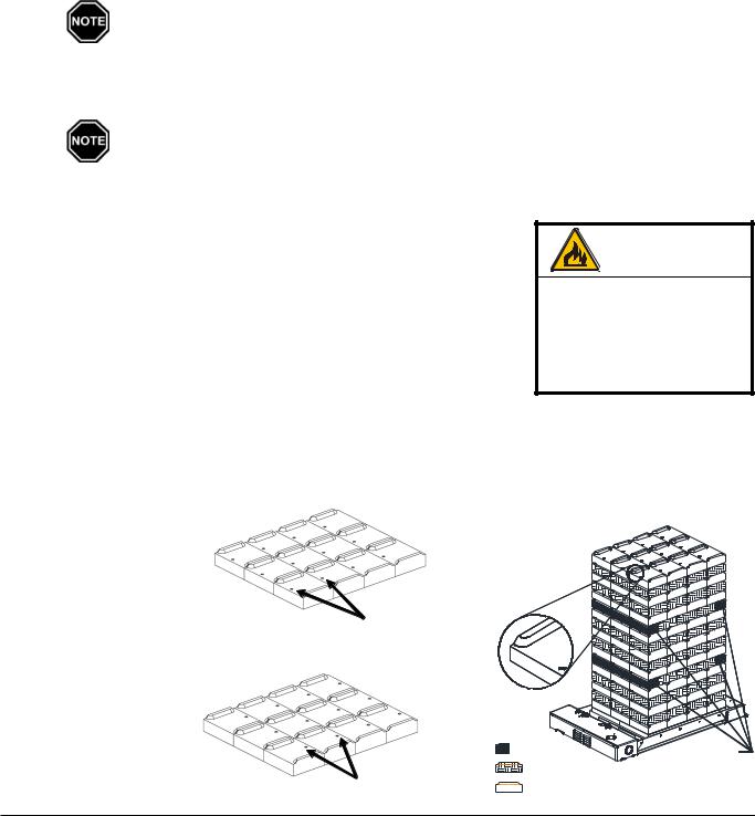
BRICK LOADING
Load the brick, one row at a time, using a left side, right side, center pattern. Start at the back of the brick core and work forward. Make sure the brick are placed so the grooved side is facing up and the ridges are on the left and right. (See Figure 6.)
BRICK INSTALLATION TIPS:
• Install bricks carefully to avoid damage to the insulation panels.
• Remove loose brick debris to prevent uneven stacking of brick, as this can make installation of the elements and the brick core temperature sensor(s) difficult.
• Brick rows MUST line up front to back and side to side.
• Half brick makes brick loading easier by evening out the stacks. proper rows and positions
as indicated in Figure 6.
• Alternate the direction of
the brick’s indicator in every other brick row. See Figures 4 and 5.
• All bricks in odd numbered rows (1, 3, 5, 7, 9, and 11) must have the indicator facing forward as shown in
Figure 4.
• All bricks in even
numbered rows will have indicator facing back.
See Figure 5.
Installation ν 3.04 |
Comfort Plus |
 Loading...