

Steelcase V.I.A. FEIJA2V User Manual
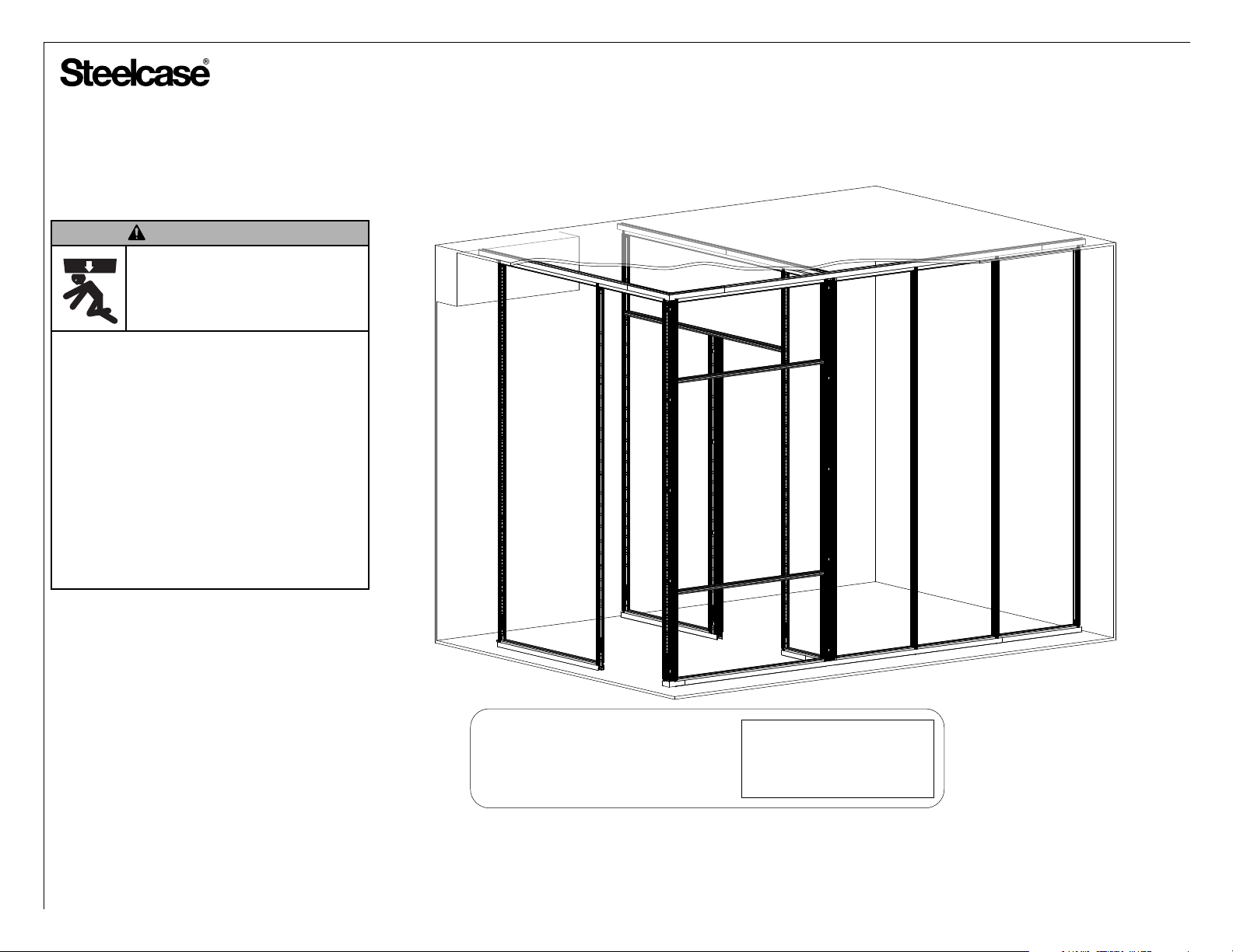
CAUTION
CRUSH HAZARD!
FAILURE TO PROPERLY SECURE
V.I.A. TO THE BUILDING COULD
RESULT IN PERSONAL INJURY.
Read the entire Assembly Directions
before beginning installation.
Building construction varies greatly. The
Building’s Engineer of Record is responsible
for the design of building floors, ceilings
and walls which V.I.A. attaches to and must
verify the adequancy of the mounting
even if provided by Steelcase.
The building owner or designated agent is
responsible for verifying that the
installation is in compliance with all local
codes and regulations.
V.I.A.™ - Frames & Structure
Non-Seismic Applications*
The building’s Engineer of Record must be
*
consulted to determine if there are any
seismic requirements.
If you have a problem, question, or request, call
your local dealer, or Steelcase Line 1 at
888.STEELCASE (888.783.3522)
for immediate action by people who want to help you.
(Outside the U.S.A., Canada, Mexico, Puerto Rico,
and the U.S. Virgin Islands, call: 1.616.247.2500)
Or visit our website: www.steelcase.com
©
2017 Steelcase Inc.
Grand Rapids, MI 49501
U.S.A.
Printed in U.S.A.
By Steelcase Inc. Grand Rapids, MI 49501-1967
www.steelcase.com/patents
Model: FEIJA2V
Ship Date: 10/09/13 Athens
Order No.: 05207605-001160
Barcode: 1PN8Z952O
Assembled By: F529602
Finishes 6249
Installation Reference Identification (IRID) Label example shown above.
Many V.I.A. Products have specific locations within the floor plan layout.
These products will be identified with an Installation Reference Identification Label.
The Installation Reference ID Label number will indicate the location of the product
within the floor plan layout. Detailed information can be found on the label
including style/model number, finish, Plan dimensions, Measured dimensions etc....
J0DEF
PH: 108.000 MH: 105.618
Page 1 of 38
939502326 Rev G
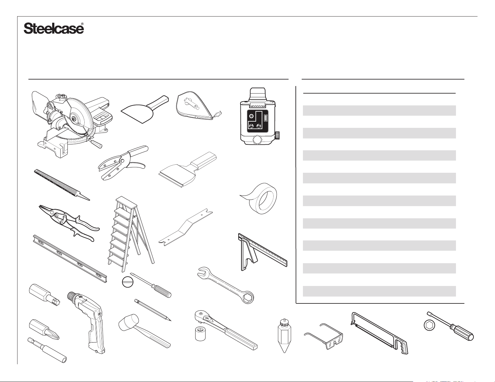
Tools Table of Contents
FRAMING LEVEL
PUTTY
KNIFE
HEAVY DUTY
UTILITY SHEAR
CHALK LINE
w/ WHITE CHALK
BASE TRIM
INSTALLATION TOOL
GLIDE
ADJUSTMENT
TOOL
LASERTRANSIT
ROTATE
POWER
SLOW
FAST
LASERTRANSIT
TIP: A 5-point alignment
self leveling laser is the
best tool to plumb, level
& square the product.
2" WIDE
MASKING TAPE
Topic Page
Layout Drawings & General Information
Installing Ceiling Channels
Installing Ceiling Track
Where to start Installing Structure
Floor Guide
Vertical Post Assembly Features
Installing Full Height Vertical Post Assembly
Junction Assemblies
Floor Track Features & Installation
Structural Horizontal Installation
Intermediate Horizontal Installation
Partial Height Vertical Post Installation
Base Trim Installation
Base Trim Removal Process
Acoustic Block Installation
Assembling a Junction Kit to a Junction
Assembling a Mini End to a Junction
3-4
5-8
9-18
19
20
21-22
23
24-25
26
27
28
29
30-33
34
34
35
36
T30
P2
LARGE & SMALL
DEAD BLOW HAMMER
8mm & 10mm
8mm & 10mm
PLUMB BOB
Changing Acoustic Seals
O
RAYB
32-TOOTH BLADE
HACKSAW
37-38
7/16” & 1/2”
Page 2 of 38
939502326 Rev G
®
A
119-1/4"
CL to outside of FE
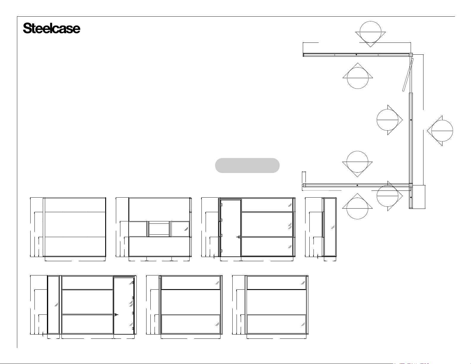
V.I.A. structures - Layout Drawings
Layout drawings give dimensions and details to help
installers determine location of product.
Ceiling track locations are taken from the centerline
dimensions on the plan view.
Locations of vertical components are found on the
plan view designated with individual IRID labels.
Locations of horizontal components are found in the
elevation views designated with individual IRID
labels.
Separate elevations are supplied for Structure, Skin
& Electrical components.
Automatic Elevations
114"
Ceiling Height
86"
38"
4242
SB12D
4242
S1362
4242
116"
Elevation A
114"
Ceiling Height
69"
38"
5F94
7360
6582
BE4C8
5F94
34" 48" 34"
Elevation B
B
Factory components are shipped with one
acoustic seal color applied. Elevation views
will indicate if a acoustic seal color changes.
See pages 37-38 for instructions on how to
replace acoustic seals.
C
144-1/8"
CL to CL
E
F
Example only
6500
S81F3
6582
BE4C8
S846AS4EC2
114"
Ceiling Height
86"
38"
1"
Elevation C
D30E6
40" 100"
3-3/4"
114"
Ceiling Height
86"
L696F
38"
1"
23"
Elevation D
CL to ME 120"
G
D
26"
CL to outside FE
114"
Ceiling Height
86"
6500
G2381
38"
1"
23" 100" 40"
GD660
G8EBA
GF791
Elevation E
114"
Ceiling Height
86"
38"
7241
Elevation F
G58C9
3062
C5175
114"
114"
Ceiling Height
86"
38"
Elevation G
WB6A0
G6207
114"
Page 3 of 38
939502326 Rev G
®
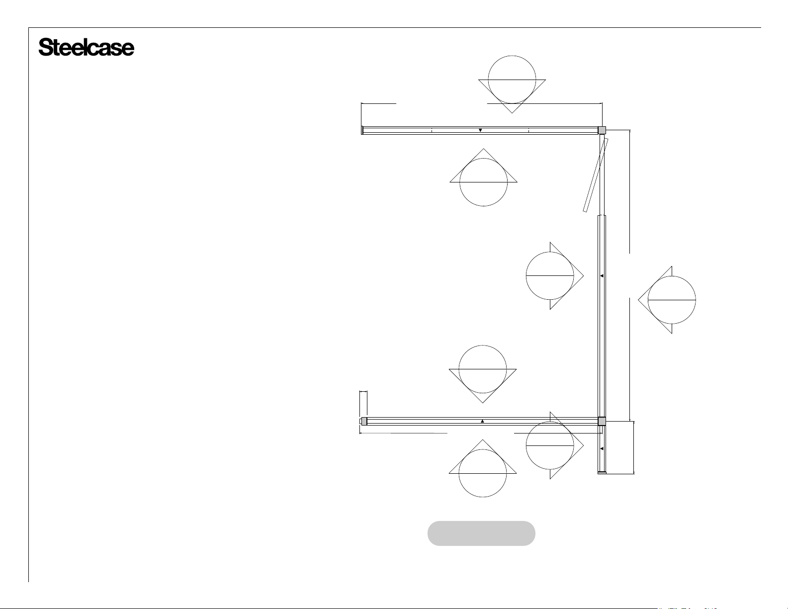
V.I.A. structures - General information
Use the centerline dimensions from the layout
drawing plan view to determine location of ceiling
track centerlines. Several methods can be used to
mark lines on the ceiling, including laser transit,
pencil marks on tape, chalk lines.
See pages 9 through 18 for additional ceiling track
information to determine cutting lengths for common
ceiling track conditions.
Transfer the ceiling centerline to the floor by means
of laser transits or plumb bob.
Make sure that the tape or lines are not visible after
install is complete.
119-1/4"
CL to outside of FE
B
A
C
144-1/8"
CL to CL
E
For the best results use a 5-point alignment self
leveling laser to transfer lines, plumb, level and square
+
to within 1/32 of an inch. The most accurate
feature to reference, while leveling, is the vertical
post system hole shown on page 21 & throughout
various V.I.A. assembly directions.
_
F
3-3/4"
CL to ME 120"
D
26"
G
CL to outside FE
Example only
Page 4 of 38
939502326 Rev G
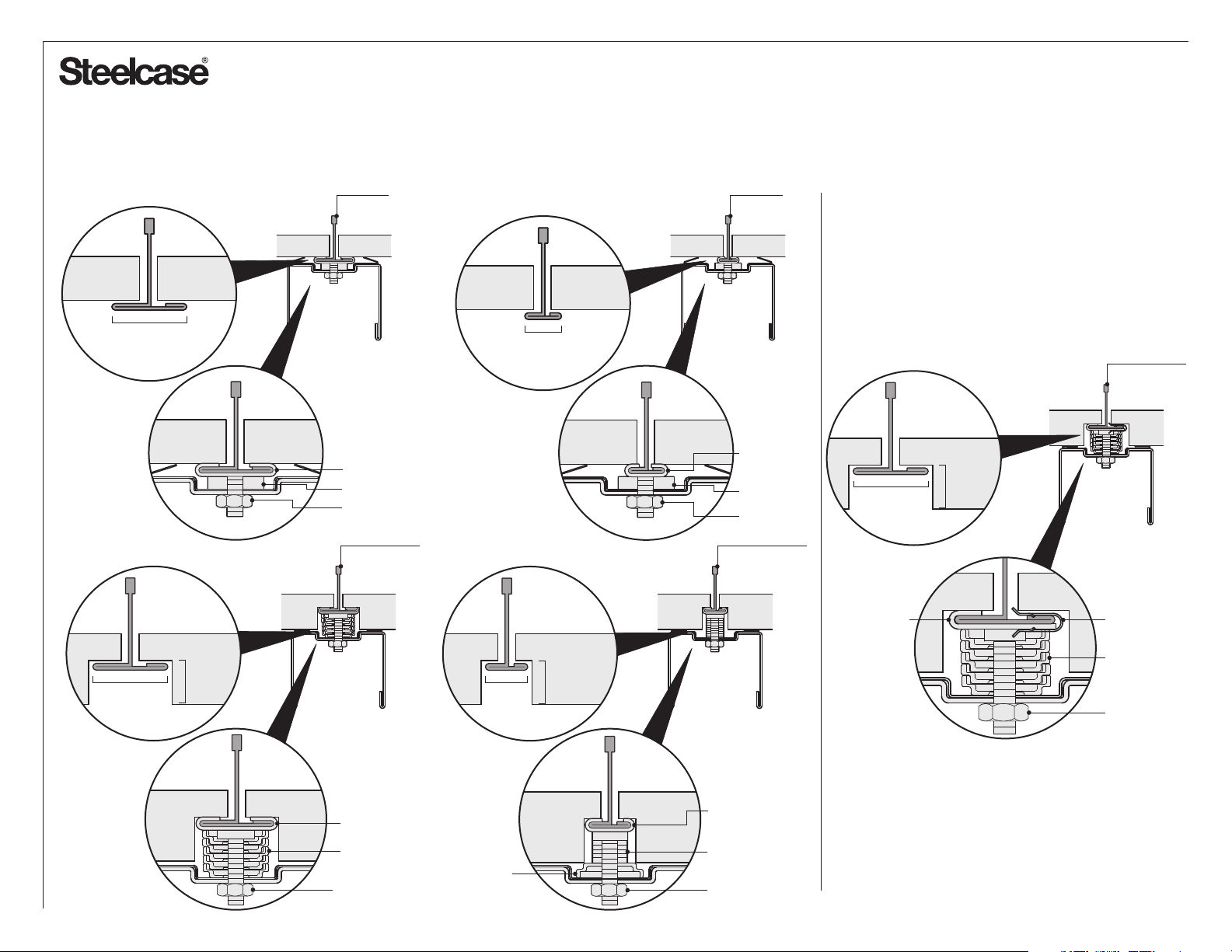
Channel Mounting Options*
The building’s designated design professional (Architect or Engineer) must verify that the ceiling grid is
*
adequate to support lateral loads imposed by V.I.A. Local codes may require independent bracing.
Exposed Tee Grids - V.I.A. Fastener Kits
1" nominal
(24mm)
1" nominal
(24mm)
1
/4",
3
/8", 1/2",
5
/8"
or
Exposed
T-clip
1/4-20 Caddy Clip Assembly
Nylon Washer
1/4-20 Hex Nut
1" Tegular Tee
9
9
/16"
nominal
(14mm)
/16" (14mm)
1
/4",
5
or
Exposed
T-clip
Exposed Tee Grids - V.I.A. Fastener Kit
Tinnerman Clip Style (Recessed Version)
1" Tegular Tee
1/4-20 Caddy
Clip Assembly
Nylon Washer
1/4-20 Hex Nut
9
/16" Tegular Tee
16"
/
1" nominal
(24mm)
#10-24 Ceiling
Clip Assembly
1
/4",
3
/8", 1/2",
5
or
/8"
Tinnerman Clip
Stack Spacers
#10-24 Hex Nut
#10-24 Caddy Clip Assembly
Stack Spacers
1 Stack Spacer
#10-24 Hex Nut
1/4-20 Caddy Clip
Assembly
Nylon Washers
1/4-20 Hex Nut
Page 5 of 38
939502326 Rev G
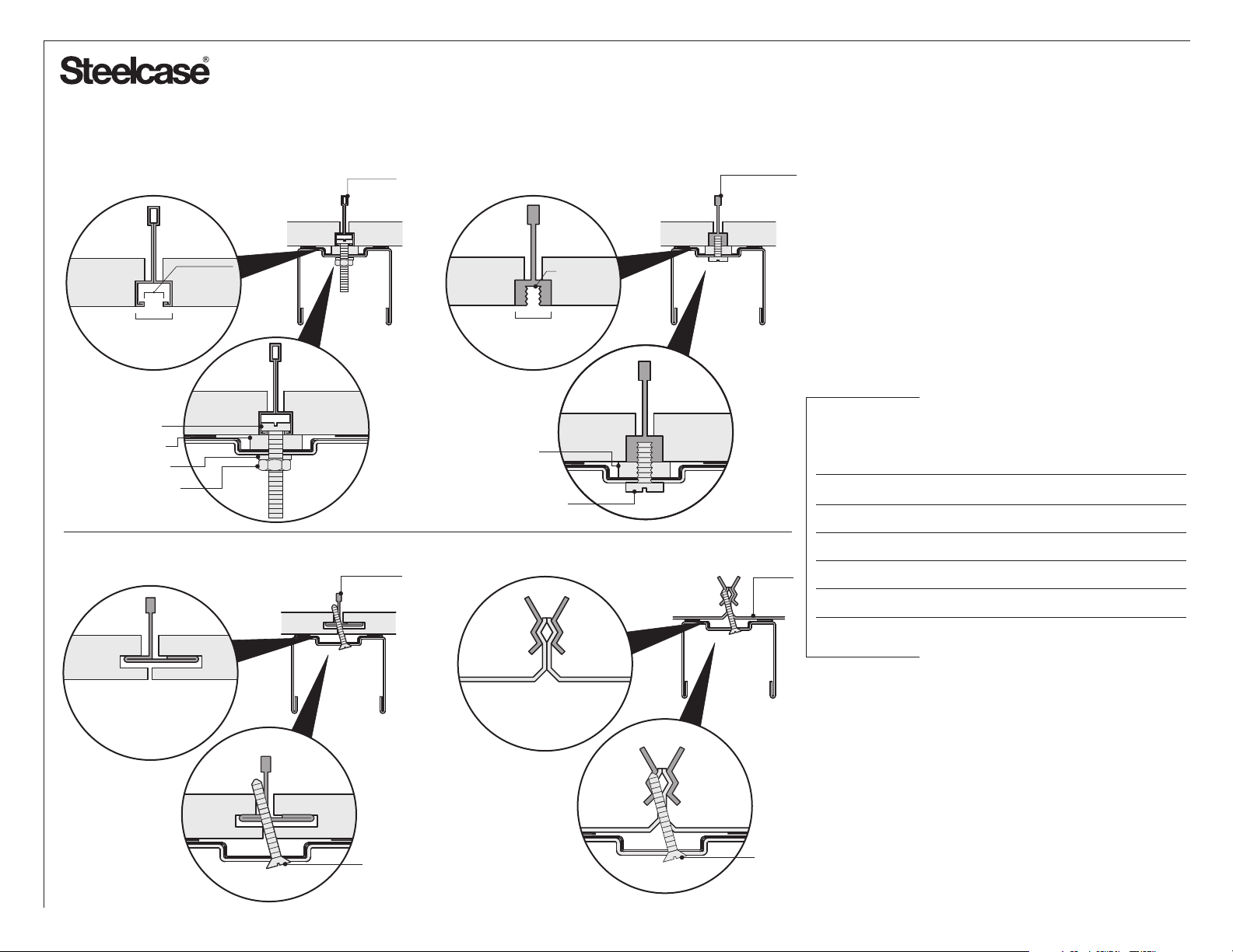
Channel Mounting Options (Continued)*
The building’s designated design professional (Architect or Engineer) must verify that the ceiling grid is
*
adequate to support lateral loads imposed by V.I.A. Local codes may require independent bracing.
Bolt and Screw Grids - V.I.A. Fastener Kits
9
/16" (14mm)
1/4-20 Donn Bolt
Nylon Washer
Nylon Washer
1/4-20 Hex Nut
slot widths
1
/8" or 1/4"
Fineline
channel
5
-18
/16
thread
9
/16" (14mm)
Nylon Washer
5/16-18 Screw
Concealed Grids - Field-Purchased Generic Fasteners
Concealed
spline
Fluted runner
Metal
ceiling
The following hardware is NOT supplied with the
product, but is commonly used for attachment
for common building construction.
NOTE: Mounting hardware must be specified/verified
by the designated design professional or approved by
the AHJ.
For these and other types of ceilings, the following
fasteners can be sourced locally by the installer:
Concealed spline
Drywall
Plaster
Concrete
Metal Pan
#7-17 x 1-5/8" Bugle Head Self-Drilling Screws
#14 - 1" Phillips Head SMS with plastic anchor
1/4-20 Toggle Bolt
Tapcon Anchor x 2"
#7-17 x 1" Bugle Head Self-Drilling Screws
Generic Sheet Metal Screw
Generic Sheet Metal Screw
Page 6 of 38
939502326 Rev G
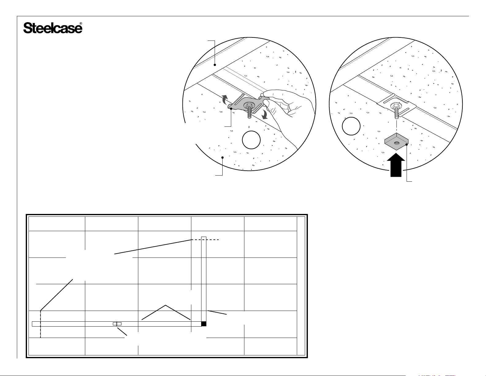
Installing Ceiling Channels
1. Attach the ceiling track to your ceiling in
compliance with local building codes and
common local practice as directed by the
lead installer. See 'channel mounting options'
for typical handling of common ceiling
conditions.
Connections should be made at least every
four feet for normal duty and at least every
two feet for heavy duty and along straight
runs, and within eight inches of the end of
any run. Each off-module connection or
junction should also have a connection
within eight inches of the joint.
CEILING GRID
1” EXPOSED CLIP SHOWN
(ONE OF SEVERAL
TYPES OF CLIPS)
CEILING TILE
1b
1a
SPACER
(ONE OF SEVERAL
TYPES OF SPACERS)
connect within 8" of
any end-of-run; this
may require building
a spanning structure above
the ceiling
X
4 feet maximum spacing
between junctions for normal
duty
XX
splice together ceiling joints
(supplied - one per ceiling channel)
X
X
X
X
X
connect within 8" of
any junction
NOTE: At this time consider electrical or
communications routing that would need to
be accommodated through the ceiling track.
Field cutting of track may be required.
Page 7 of 38
939502326 Rev G
CUT A SEAL PIECE BIG ENOUGH TO BLOCK
SOUND AND LIGHT IN BOTH DIRECTIONS
Installing Sound & Light Seal for
Tegular Ceiling
NOTE: Cut and place pieces of seal
anywhere that sound or light can travel
through the tegular grid.
Applications
CEILING TRACK PERPENDICULAR TO GRIDS
CEILING CLIP
SEAL
CEILING TRACK DIAGONALLY ACROSS GRIDS
CEILING TRACK INLINE WITH GRID
SEAL
CEILING
CLIP
TEGULAR
CEILING GRID
SEAL TO ONE SIDE
OF CEILING CLIP
AND WASHER STACK
SEAL
Installing Ceiling Channels
The Christmas Tree fasteners and tape serve
only as a shipping and assembly aid. They are
not required after the ceiling track is installed.
Move or remove them as needed to accommodate
the ceiling track clips.
If the channel is cut, it may be helpful to add a
piece of tape to one end. This maintains alignment
between the seal and steel channel while attaching
the channel to the ceiling.
CHRISTMAS TREE FASTENER
TAPE
Page 8 of 38
939502326 Rev G
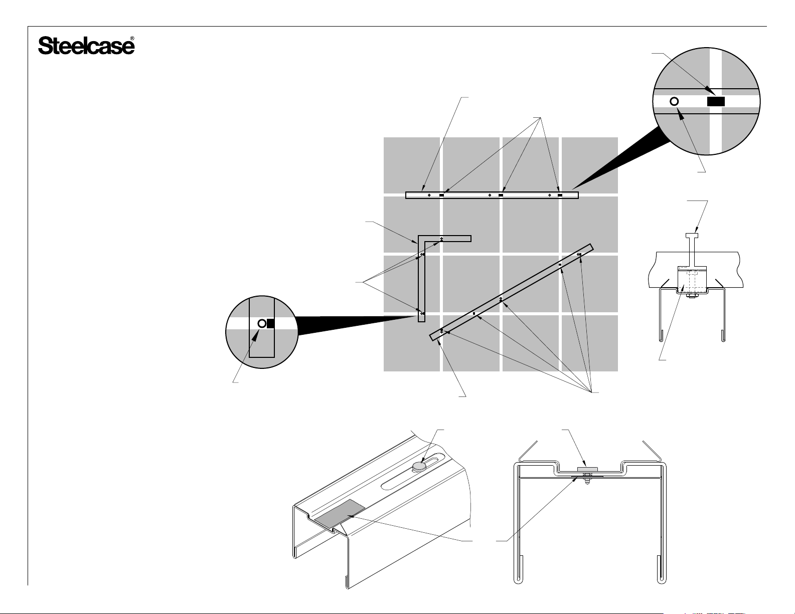
®
CEILING TRACK
INSTALLATION
SEAL
CEILING TRACK
SPLICE
SELF DRILLING
SCREWS
SPLICE
SELF DRILLING SCREW
90o CEILING TRACK (SHOWN)
120o CEILING TRACK
135o CEILING TRACK
NOTE: Specifiable angle ceiling track will have an
installation reference ID label placed on it and has a
specific location in the floor plan.
SPLICE
SPECIFIABLE ANGLE
CEILING TRACK
SPLICE
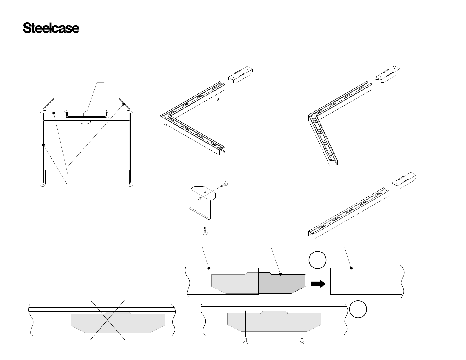
Each ceiling track comes with one (1) splice.
1.
When installing ceiling track butt joints, center the
splice as shown.
2. A feature of the straight ceiling track is the
center hole spacing matches most ceiling grids.
3. Two self tapping screws are provided to secure
the splice connection after the ceiling track
is installed.
WRONG
CEILING TRACK
BRACKET WITH
TWO (2) #6-20 x 3/8”
SELF DRILLING
SCREWS
CEILING TRACK CEILING TRACK
SPLICE
STRAIGHT
CEILING TRACK
1
3
TWO (2) #6-20 x 3/8”
SELF DRILLING
SCREWS
Page 9 of 38
939502326 Rev G
®
CEILING TRACK
INSTALLATION (cont.)
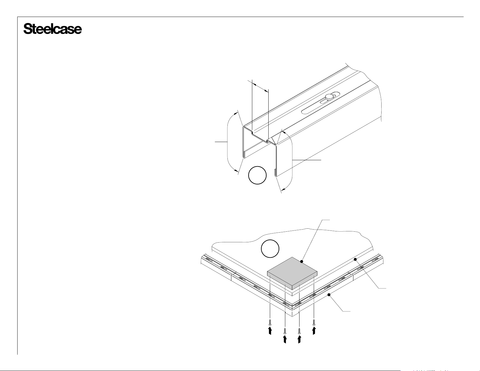
TIP: Before cutting the ceiling track, consider
locations of pre-punched holes to minimize the
need for additional holes.
3. Use a saw to cut ceiling track when required.
Remove all burrs with a file. Square cuts will
insure best appearence. When routing power or
communication, sheet metal shears can be
used to cut a hole in the top of the ceiling track.
Avoid cutting the side of the ceiling track
because these cuts will be visible.
4. To create a tight fit when a corner ceiling
track lacks structure, a wood block can be
installed above the ceiling tile for reinforcement.
NO
CUTS
AREA
CUT
AREA
NO
CUTS
AREA
3
WOOD BLOCK
4
CEILING TILE
CORNER
CEILING TRACK
Page 10 of 38
939502326 Rev G
®
CEILING TRACK
INSTALLATION (cont.)
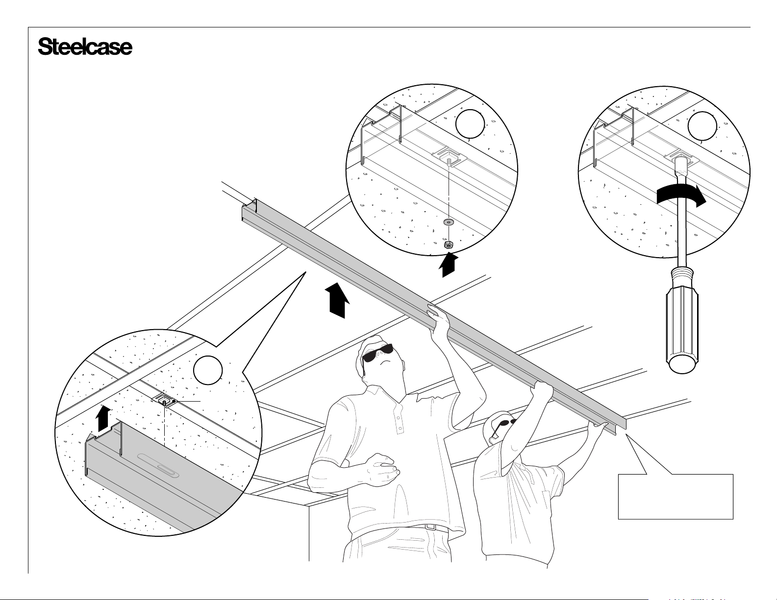
Refer to ceiling clip mounting for
5.
information on available ceiling fastener
types and locations (Showing typical
ceiling fastener for general installation
purposes).
6. Take care to insure that the ceiling
track seal seats consistently.
6
CADDY CLIP
5a
5b
Install ceiling track flush
against building wall if
floor plan indicates.
Page 11 of 38
939502326 Rev G
®
CEILING TRACK
INSTALLATION (cont.)
7a
1/16” BACK
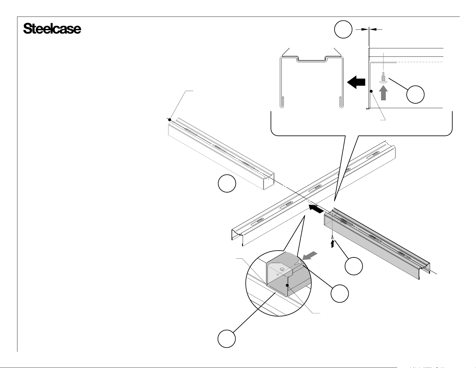
When a ‘T’ intersection is required,
7.
attach the ceiling track bracket to 1/16”
back from end of ceiling track as shown
(7a) and attach with self-drilling screw
to the ceiling track (7b). Aligning to the
centerline of the floor plan, hook ceiling
track bracket (7c) to the other ceiling
track and attach with self-drilling screw
as shown (7d).
Repeat the process on the other side if
an ‘X’ intersection is required (7e).
FLOOR PLAN
CENTERLINE
7e
HOOK TO
CEILING TRACK
7b
CEILING TRACK
BRACKET
7b
7c
7d
CEILING TRACK
BRACKET
Page 12 of 38
939502326 Rev G
 Loading...