

Page 1

media:scape® Technology Manual
400-0571-012 1
Americas Tech Support: PHONE: 1.800.334.4922 / EMAIL: [email protected]
EMEA Tech Support: PHONE: +33 3 88 13 36 36 / EMAIL: [email protected]
TECHNICAL SUPPORT
For the most current technical support documents and files, please visit http://techsupport.Steelcase.com
In the Americas, contact Steelcase USA Technical Support:
PHONE: 1.800.334.4922
24 -hour support Monday through Friday
Outside the Americas, contact Steelcase Europe/Asia Technical Support:
PHONE: +33 3 88 13 36 36
Support available in English, French and German. Monday through Friday 7:30 to 18:30 US Central Time
This user guide is compatible with 2.0.8 firmware
Page 2
media:scape® Technology Manual
400-0571-012 2
Americas Tech Support: PHONE: 1.800.334.4922 / EMAIL: [email protected]
EMEA Tech Support: PHONE: +33 3 88 13 36 36 / EMAIL: [email protected]
Welcome!
We greatly appreciate your purchase. We are sure you will find it reliable
and easy to use. Superior performance for the right price, backed by solid
technical and customer support is what Steelcase has to offer. We are
committed to providing Signal Management Solutions® to the most
demanding audiovisual installations at competitive pricing. We welcome
you to join the ranks of our many satisfied customers worldwide.
1. Precautions and Safety Warnings
Please read this manual before using your SP106-201/202 and keep it
handy for future reference. These safety instructions are to ensure the
long life of your SP106-201/202 and to prevent fire and shock hazards.
1.1 Handling
Handle the SP106-201/202 carefully. Dropping or jarring can cause
damage.
To prevent fire or shock, do not expose this unit to water or moisture.
Do not place the SP106-201/202 in direct sunlight, near heaters, or
heat-radiating appliances, or near any liquid. Exposure to direct
sunlight, smoke, or steam can harm internal components.
Do not pull any cables that are attached to the SP106-201/202.
If the SP106-201/202 is not used for an extended period, disconnect
the power adapter from the wall to avoid damage.
1.2 Cleaning
Unplug the SP106-201/202 adapter before cleaning.
Clean only with a dry cloth. Never use detergents or solvents. Do not
use a wet cloth or water to clean.
1.3 FCC Notice
This device complies with Part 15 of the FCC Rules. Operation is
subject to the following two conditions: (1) This device may not
cause harmful interference, and (2) this device must accept any
interference received, including interference that may cause
undesired operation.
This equipment has been tested and found to comply with the limits
for a Class A digital device, pursuant to Part 15 of the FCC Rules.
These limits are designed to provide reasonable protection against
harmful interference when the equipment is operated in a
commercial environment. This equipment generates, uses, and can
radiate radio frequency energy and if not installed and used in
accordance with instructions found herein, may cause harmful
interference to radio communications. Operation of this equipment in
a residential area is likely to cause harmful interference in which
case the user will be required to correct the interference at their
expense.
Any changes or modifications to the unit not expressly approved by
Steelcase, Inc. could void the user’s authority to operate the
equipment
2. Installation Procedures
NOTE: PUCK inputs are not HDMI compatible. Do not plug anything into these ports except PUCKs. Metal tabs are provided
to prevent use of standard HDMI connectors. Do not mend or break metal tabs!
Step 1. Read the entire manual to become familiar with the SP106-201/202, its features and documentation.
Step 2. Use only Steelcase provided cables or those attached to the PUCKs.
Step 3. Connect external PC or video conferencing equipment to AUX ports.
Step 4. Connect all PUCKs to the switcher. If necessary, use
SP106-217 PUCK extension cables.
Step 5. Verify that the wake-up switch is installed in the table
and connected to the switcher’s CTRL input.
Step 6. Connect the switcher to the DC power adapter
provided. The switcher is ready to use.
3. Limited Warranty/Return Policies
Please contact Steelcase for details on warranty and return policies.
Page 3
media:scape® Technology Manual
400-0571-012 3
Americas Tech Support: PHONE: 1.800.334.4922 / EMAIL: [email protected]
EMEA Tech Support: PHONE: +33 3 88 13 36 36 / EMAIL: [email protected]
4. Technical Specifications
Specifications are subject to change. See www.Steelcase.com for up-to-date information.
Features/Description
SP106-201/202
Input Connectors
(first # applies to 201/202)
Video, Audio and
Power (PUCK)
HDMI F, Type A (8/4)
PC/Videoconference Video
HDMI F, Type A (3/2)
PC/Videoconference Audio
3.5 mm jack (3/2)
DC Power
2.5 mm jack (1)
Output Connectors
Video/Audio/Control
HDMI F, Type A (4/2)
Compatibility
Signal Types
VGA, HDMI, DP & MINI DP
Video Signal
Resolutions
VGA: up to WUXGA
1920x1200@60Hz
HD: up to 1080p
1920x1080@60Hz
Accessories Included
Power Adapter
Mfr: GlobTek Inc.
Model: GT-4113-6012-T3
I/P: 100-240VAC,
50/60Hz, 1.5A
O/P: DC12V, 6.0A
115 VAC Power Cord
(PC5301US)
Supply: NEMA 5-15P
Equip.: IEC60320-C13
Optional Accessories
HDMI PUCK
SP106-203
VGA PUCK
SP106-204
DP PUCK
SP106-205
MINI DP PUCK
SP106-206
PUCK Extension Cable
SP106-217 (50 inch)
PUCK Extension Cable
SP106-218 (25ft )
On/Off/Standby mode Switch
SP106-105
Replacement Fan for Switcher
SP106-240
Table 1. SP106-201/202 General
Mechanical
SP106-201/202
Material/Color
Aluminum/Black
Length
10.0 in (254 mm)
Width
5.5 in (140 mm)
Height
1.6 in (41 mm)
Net Weight
2.1 lb. (1.0 kg)
Shipping Weight (approx.)
2.8 lb. (1.3 kg)
T Operating
10C-35C
T Maximum
50C
Humidity
90 non-condensing
Table 2. SP106-201/202 Mechanical
Electrical
SP106-201/202
Input to PUCK
Video+Audio
PC/Videoconference Audio Inputs
PC Inputs (1,2,3) for the SP106201 & PC inputs (1,2) for SP106202
HDMI with HDCP
HDMI
Main Outputs
Video+Audio+Control
Power Consumption
External Adapter: 12 VDC
6.0 A (72 W) max.
Table 3. SP106-201/202 Electrical
Page 4
media:scape® Technology Manual
400-0571-012 4
Americas Tech Support: PHONE: 1.800.334.4922 / EMAIL: [email protected]
EMEA Tech Support: PHONE: +33 3 88 13 36 36 / EMAIL: [email protected]
Features/Description
SP106-203
Input Cable
Video
Standard HDMI Type-A (M)
Length
11.02 inches (0.92 ft.)
Output Cable
Video+ Communication
Custom HDMI Type-A (M)
Length
80.98 inches (6.75 ft.)
Compatibility
Signal types
HDMI with HDCP Support
Signal resolution
Up to 1080p 1920x1080@60
Switchers
SP106-201/202
Table 4. SP106-203 HDMI PUCK General
Mechanical
SP106-203 HDMI PUCK
Material
Aluminum/Plastic/Rubber
Color
Silver
Height (body only)
2.56 in (65 mm)
Width (body only)
2.56 in (65 mm)
Depth (body only)
0.93 in (24 mm)
Weight
5 oz. (0.14 kg)
T° Operating
10°C-45°C
T° Maximum
65°C
Humidity
90% non-condensing
MTBF (calc.)
50,000 hrs.
Table 5. SP106-203 HDMI PUCK Mechanical
Electrical
SP106-203 HDMI PUCK
Input Signals
Video
HDMI Standard
Switcher Side Output Signals
HDMI
HDMI+ Communication
Signal Level
HD Digital
Power (from switcher)
+5V
70 mA
Total Power
0.035 W Max
Table 6. SP106-203 HDMI PUCK Electrical
Page 5
media:scape® Technology Manual
400-0571-012 5
Americas Tech Support: PHONE: 1.800.334.4922 / EMAIL: [email protected]
EMEA Tech Support: PHONE: +33 3 88 13 36 36 / EMAIL: [email protected]
Features/Description
SP106-204
Input Cable
Video
15-pin HD (M)
Length
11.02 inches (0.92 ft.)
Output Cable
Video+ Communication
Custom HDMI Type-A (M)
Length
80.98 inches (6.75 ft.)
Compatibility
Signal types
RGBHV
Signal resolution
Up to WUXGA 1920x1200@60
Switchers
SP106-201/202
Table 7. SP106-204 VGA PUCK General
Mechanical
SP106-204 VGA PUCK
Material
Aluminum/Plastic/Rubber
Color
Silver
Height (body only)
2.56 in (65 mm)
Width (body only)
2.56 in (65 mm)
Depth (body only)
0.93 in (24 mm)
Weight
5 oz. (0.14 kg)
T° Operating
10°C-45°C
T° Maximum
65°C
Humidity
90% non-condensing
MTBF (calc.)
50,000 hrs.
Table 8. SP106-204 VGA PUCK Mechanical
Electrical
SP106-204 VGA PUCK
Input Signals
Video (RGB)
1.0 Vp-p max
Horizontal & Vertical Sync
0.5 Vp-p TTL
Analog Audio
1.0 Vp-p max
Switcher Side Output Signals
HDMI
HDMI+ Communication
Signal Level
HD Digital
Power (from switcher)
+5V
75 mA
Total Power
0.038 W Max
Table 9. SP106-203 VGA PUCK Electrical
Page 6
media:scape® Technology Manual
400-0571-012 6
Americas Tech Support: PHONE: 1.800.334.4922 / EMAIL: [email protected]
EMEA Tech Support: PHONE: +33 3 88 13 36 36 / EMAIL: [email protected]
Features/Description
SP106-205
Input Cable
Video
Standard Display port (M)
Length
11.02 inches (0.92 ft.)
Output Cable
Video+ Communication
Custom HDMI Type-A (M)
Length
80.98 inches (6.75 ft.)
Compatibility
Signal types
Display port with HDCP Support
Signal resolution
Up to 1080p 1920x1080@60
Switchers
SP106-201/202
Table 10. SP106-205 Display Port PUCK General
Mechanical
SP106-205 DisplayPort PUCK
Material
Aluminum/Plastic/Rubber
Color
Silver
Height (body only)
2.56 in (65 mm)
Width (body only)
2.56 in (65 mm)
Depth (body only)
0.93 in (24 mm)
Weight
5 oz. (0.14 kg)
T° Operating
10°C-45°C
T° Maximum
65°C
Humidity
90% non-condensing
MTBF (calc.)
50,000 hrs.
Table 11. SP106-205- Display Port PUCK Mechanical
Electrical
SP106-205 Display Port PUCK
Input Signals
Video
Display Port Standard
Switcher Side Output Signals
HDMI
HDMI+ Communication
Signal Level
HD Digital
Power (from switcher)
+5V
70 mA
Total Power
0.035 W Max
Table 12. SP106-205 Display Port PUCK Electrical
Page 7
media:scape® Technology Manual
400-0571-012 7
Americas Tech Support: PHONE: 1.800.334.4922 / EMAIL: [email protected]
EMEA Tech Support: PHONE: +33 3 88 13 36 36 / EMAIL: [email protected]
Features/Description
SP106-206
Input Cable
Video
Standard Mini Display port (M)
Length
11.02 inches (0.92 ft.)
Output Cable
Video+ Communication
Custom HDMI Type-A (M)
Length
80.98 inches (6.75 ft.)
Compatibility
Signal types
Mini Display port with HDCP Support
Signal resolution
Up to 1080p 1920x1080@60
Switchers
SP106-201/202
Table 13. SP106-206 Mini Display Port PUCK General
Mechanical
SP106-206 Mini Display Port
PUCK
Material
Aluminum/Plastic/Rubber
Color
Silver
Height (body only)
2.56 in (65 mm)
Width (body only)
2.56 in (65 mm)
Depth (body only)
0.93 in (24 mm)
Weight
5 oz. (0.14 kg)
T° Operating
10°C-45°C
T° Maximum
65°C
Humidity
90% non-condensing
MTBF (calc.)
50,000 hrs.
Table 14. SP106-206 Mini-Display Port PUCK Mechanical
Electrical
SP106-205 Mini Display Port
PUCK
Input Signals
Video
Display Port Standard
Switcher Side Output Signals
HDMI
HDMI+ Communication
Signal Level
HD Digital
Power (from switcher)
+5V
70 mA
Total Power
0.035 W Max
Table 15. SP106-206 Mini Display Port PUCK Electrical
Page 8
media:scape® Technology Manual
400-0571-012 8
Americas Tech Support: PHONE: 1.800.334.4922 / EMAIL: [email protected]
EMEA Tech Support: PHONE: +33 3 88 13 36 36 / EMAIL: [email protected]
5. About Your 8x4 media:scape System
Independent control of 4 audio/video outputs
Built-in walk up video experience
Auto-shutdown when signal is disconnected
Up to 8 user interface control units (PUCKs)
Designed to work with Video Conferencing
The SP106-201 System is an 8x4 Video+Audio Matrix Switcher designed
to be used as part of an integrated audiovisual system inside
media:scape®.
The PUCKs receive video and audio inputs from laptops or other desktop
or mobile devices. Each m:s can accept 8 PUCK inputs from presenters
and 3 additional AUX inputs for room PC or video conferencing.
Note: Switching between content protected sources (HDCP) may
take 2 to 3 seconds longer than switching between nonprotected sources.
Each presenter can select the destination display or override the current
presenter. There is no need to disconnect the cables. Switcher control is
done through the PUCKs.
8x4 Video + Audio Matrix Switcher
8 video + audio PUCK inputs
3 AUX inputs for PC and video conferencing
4 user-configurable outputs
The SP106-201 Matrix Switcher has 8 PUCK inputs, 3 PC/video
conferencing inputs, 4 outputs. The 3 AUX inputs (Inputs 9, 10, and 11)
also have associated audio inputs. The switcher provides connectivity of
any PUCK input video signal to any of the 4 enabled outputs. It controls
the monitor’s stand-by mode depending on the system setup.
4 x 2 Video + Audio Matrix Switcher
4 Video + audio PUCK inputs
2 AUX inputs for PC and video conferencing
2 user-configured outputs.
The SP106-202 Matrix Switcher has 4 PUCK inputs, 2 PC/video
conferencing inputs and 2 outputs. The 2 AUX inputs (Inputs 9, 10) also
have associated audio inputs. The switcher provides connectivity of any
PUCK input video signal to any of the 2 enabled outputs. It controls the
monitor’s stand-by mode depending on the system setup.
Handset (PUCK) Control
Personal User Control Key
Touch-sensitive control surface
Dual color icon status indicators
Each PUCK has two cables: one is permanently attached to the switcher
and the other is used for direct connection to a laptop or other video
sources. Each PUCK has audio input that is combined with HDMI signal.
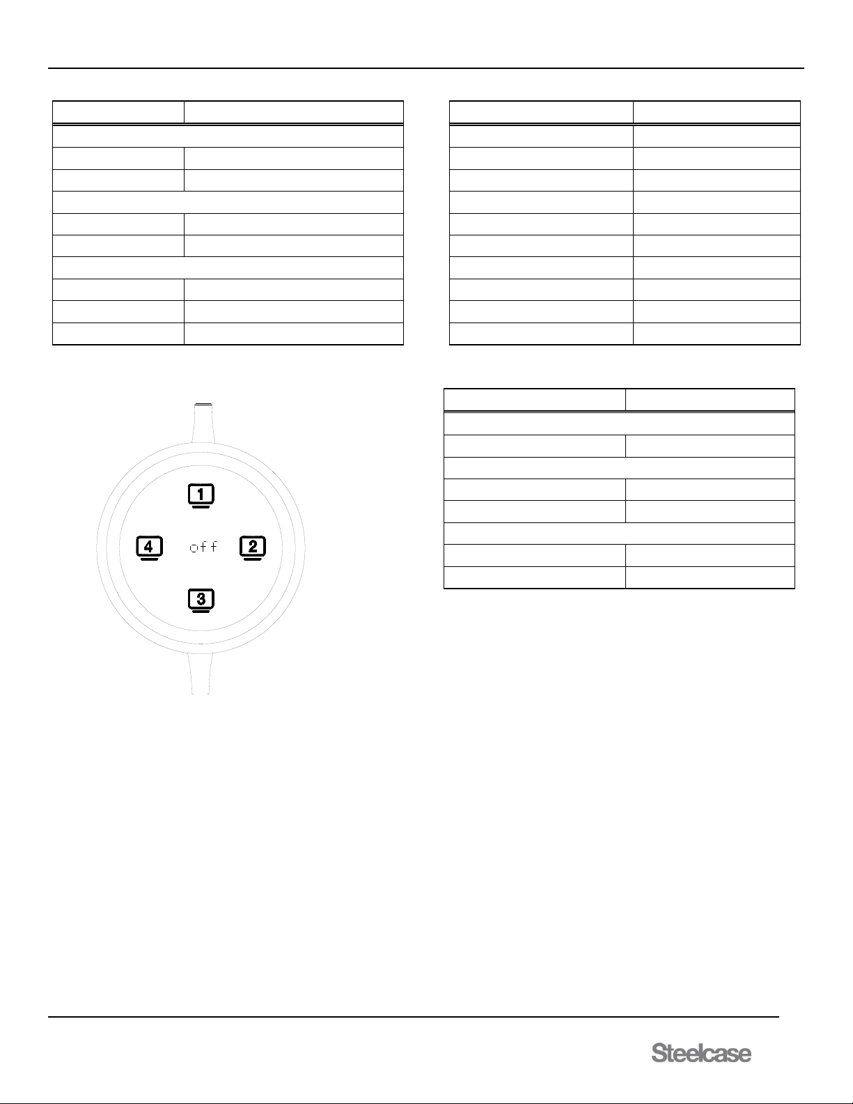
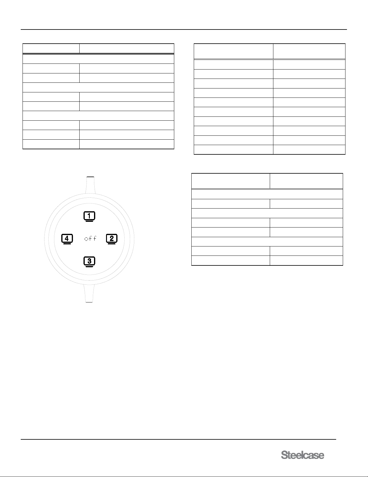
A green icon on the PUCK indicates the PUCK’s signal is presently on
an output; white indicates there is no connection to an output. As
presenters take turns, the previous presenter’s connection is broken in
favor of the next presenter. If the input device is disconnected, the PUCK
enters “Sleep Mode” by turning off all icons. As soon as a video signal is
reapplied, the PUCK "wakes up" displaying available outputs.
Power/Stand-by Button
Power control of switcher
Display OSD for configuration
Display firmware upgrade option
If the switcher does not have any active signals applied, the power
button resets the standby mode timer and plays the introduction video.
When the timer expires, the switcher goes into standby mode. The LED
on the switch is white when the system is in standby mode and green
during normal operation.
How it works
Media:scape is designed for all around collaboration.
Open the media well and remove a PUCK.
Connect the PUCK to the laptop or mobile device
Share what is on the device by pressing the illuminated icons of
available displays. Other users can press the illuminated icons to
present as well when connected.
Ways to configure switcher
Easiest way to configure the switcher is through OSD (On Screen
Display). Another way to configure the switcher is through use of a
terminal program interfacing with the Ethernet port of the media:scape.
Both of these methods are explained in detail later in the manual.
Page 9
media:scape® Technology Manual
400-0571-012 9
Americas Tech Support: PHONE: 1.800.334.4922 / EMAIL: [email protected]
EMEA Tech Support: PHONE: +33 3 88 13 36 36 / EMAIL: [email protected]
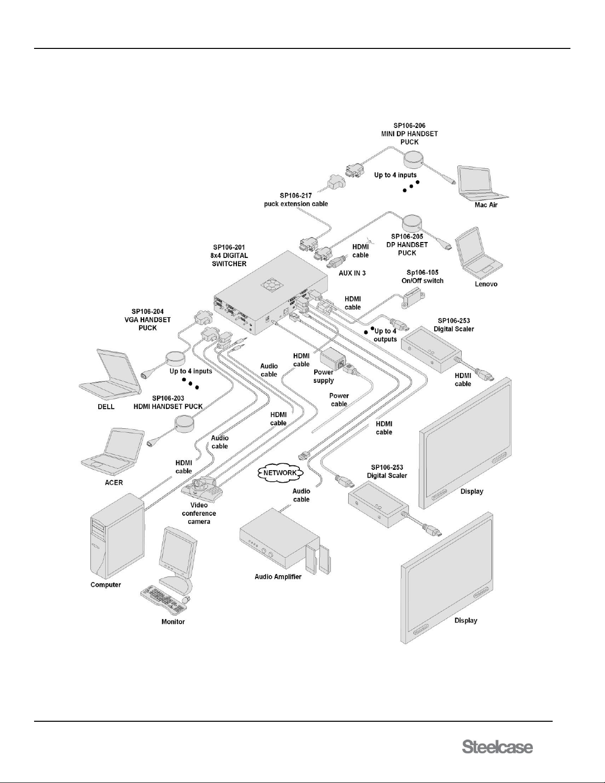
6. Application Diagrams
Diagram 1: Typical Setup for SP106-201 8x4 switcher
Page 10
media:scape® Technology Manual
400-0571-012 10
Americas Tech Support: PHONE: 1.800.334.4922 / EMAIL: [email protected]
EMEA Tech Support: PHONE: +33 3 88 13 36 36 / EMAIL: [email protected]
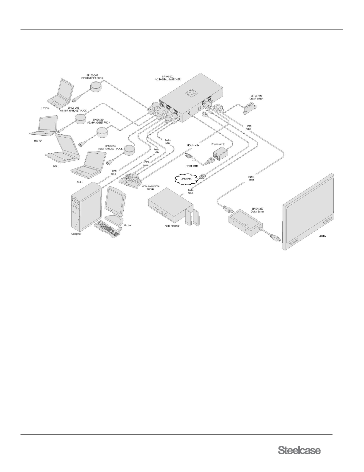
Diagram 2: Typical Setup for SP106-202 4x2 switcher
Page 11
media:scape® Technology Manual
400-0571-012 11
Americas Tech Support: PHONE: 1.800.334.4922 / EMAIL: [email protected]
EMEA Tech Support: PHONE: +33 3 88 13 36 36 / EMAIL: [email protected]
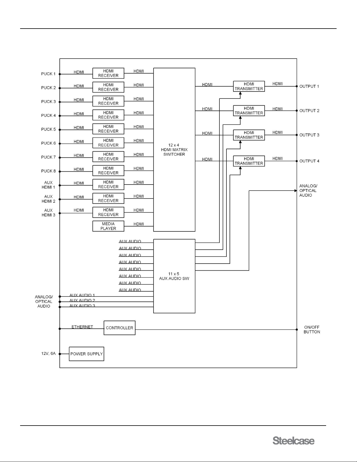
Diagram 3: Block Diagram for SP106-201 8x4 switcher
Page 12
media:scape® Technology Manual
400-0571-012 12
Americas Tech Support: PHONE: 1.800.334.4922 / EMAIL: [email protected]
EMEA Tech Support: PHONE: +33 3 88 13 36 36 / EMAIL: [email protected]
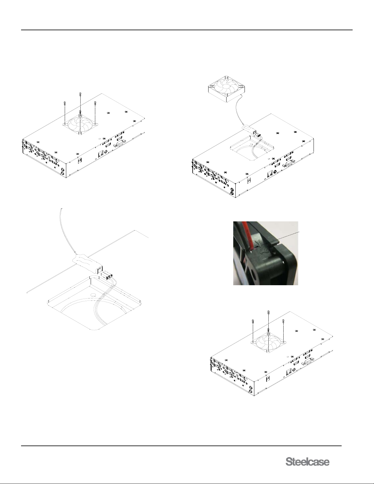
Diagram 4: Fan Replacement for SP106-201/202 switcher
Fan Replacement
Step 1: Remove the 4 screws using a
Phillips screwdriver.
Step 2: Safely pull the fan away from the
enclosure.
Step 3: Disconnect fan at the connector
and install with replacement fan
Step 5: After feeding the cable through the
square opening, insert fan assembly into
position before securing with screws.
Note: During fan replacement make sure that
the label of the fan is facing inside of unit.
Step 4: During new fan installation install wires
of fan between openings in plastic, as shown.
Page 13
media:scape® Technology Manual
400-0571-012 13
Americas Tech Support: PHONE: 1.800.334.4922 / EMAIL: [email protected]
EMEA Tech Support: PHONE: +33 3 88 13 36 36 / EMAIL: [email protected]
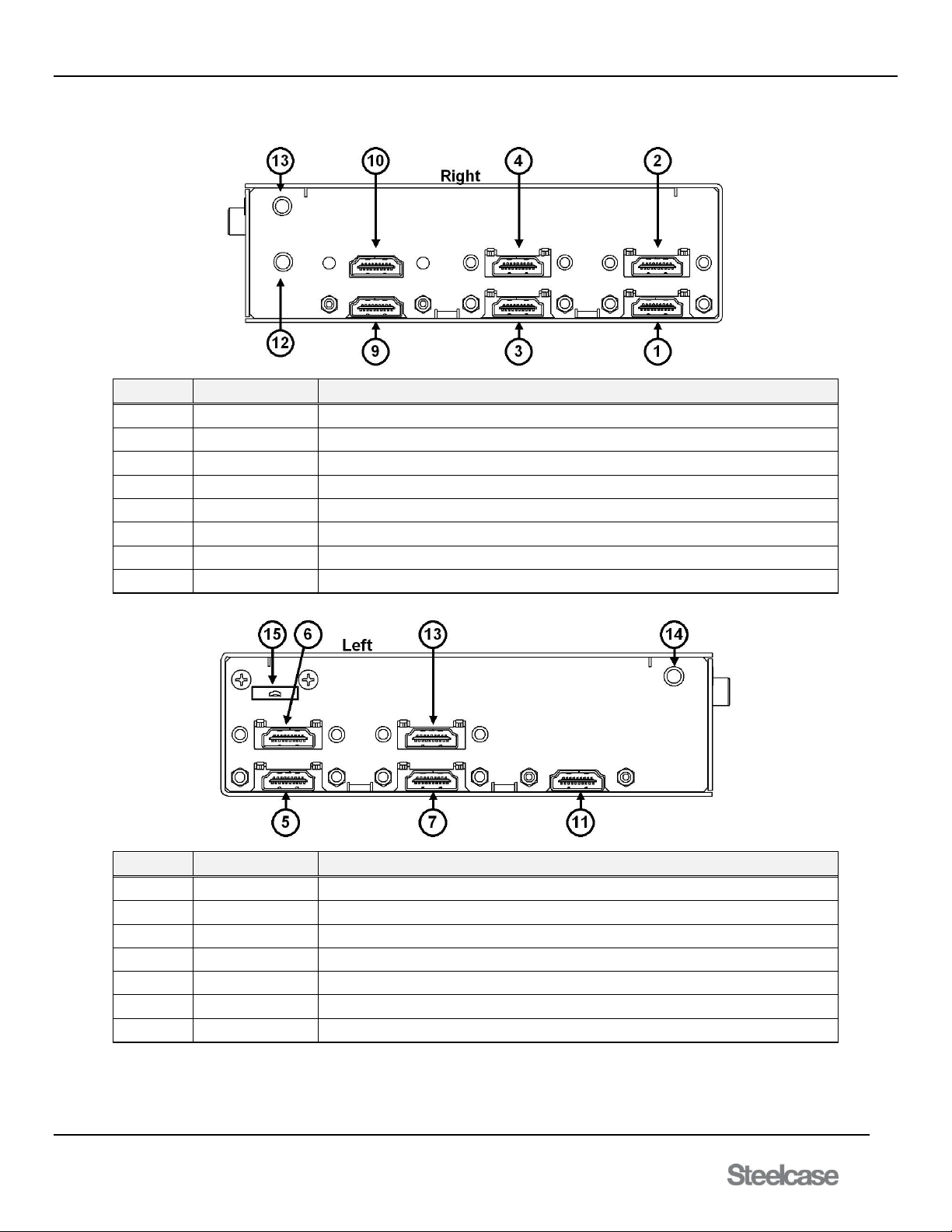
Diagram 5: Component View (Right & Left Input side)
Number
Port
Description
1
PUCK 1
Digital input for analog/digital PUCKS (Not standard HDMI ports)
2
PUCK 2
Digital input for analog/digital PUCKS (Not standard HDMI ports)
3
PUCK 3
Digital input for analog/digital PUCKS (Not standard HDMI ports)
4
PUCK 4
Digital input for analog/digital PUCKS (Not standard HDMI ports)
9
AUX 1
Standard HDMI Input 9 (labeled as AUX 1 on switcher)
10
AUX 2
Standard HDMI Input 10 (labeled as AUX 2 on switcher)
12
AUX 1 Audio
Analog/Digital 3.5mm jack external AUX audio input
13
AUX 2 Audio
Analog/Digital 3.5mm jack external AUX audio input
Number
Port
Description
5
PUCK 5
Digital input for analog/digital PUCKS (Not standard HDMI ports)
6
PUCK 6
Digital input for analog/digital PUCKS (Not standard HDMI ports)
7
PUCK 7
Digital input for analog/digital PUCKS (Not standard HDMI ports)
8
PUCK 8
Digital input for analog/digital PUCKS (Not standard HDMI ports)
11
AUX 3
Standard HDMI Input 11 (labeled as AUX 3 on switcher)
14
AUX 3 Audio
Analog/Digital 3.5mm jack external AUX audio input
15
USB Drive
Walk Up Experience Memory
Page 14
media:scape® Technology Manual
400-0571-012 14
Americas Tech Support: PHONE: 1.800.334.4922 / EMAIL: [email protected]
EMEA Tech Support: PHONE: +33 3 88 13 36 36 / EMAIL: [email protected]
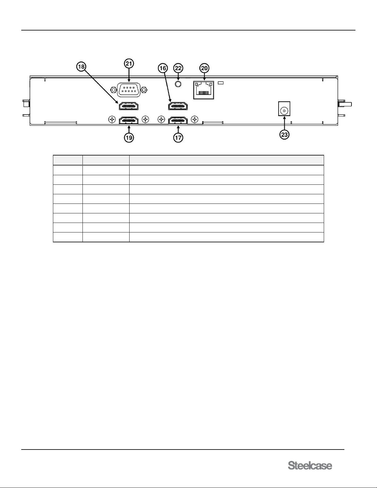
Diagram 6: Component View (Output side)
Number
Component
Detail
16
Output 1
Digital HDMI output
17
Output 2
Digital HDMI output
18
Output 3
Digital HDMI output
19
Output 4
Digital HDMI output
20
Ethernet RJ45
Use for maintenance and switcher configuration
21
Female DB9
Control connector for the power button located on the bezel
22
Audio Out
3.5mm jack external audio output
23
DC Power
12V 2.5mm Jack
Page 15

media:scape® Technology Manual
400-0571-012 15
Americas Tech Support: PHONE: 1.800.334.4922 / EMAIL: [email protected]
EMEA Tech Support: PHONE: +33 3 88 13 36 36 / EMAIL: [email protected]
7. Operation
7.1 Collaborative (PUCK) Control
7.1.1 PUCK Control
Each PUCK has 5 touch-sensitive keys that are represented by icons
illuminated from beneath the PUCK’s surface: 1, 2, 3, 4, and Off. The
icons are only visible when the PUCK is connected to an active video
source, such as a laptop, and represent switcher output states in relation
to themselves.
After the PUCK is connected to an active video source, its icons are
illuminated in white including the outer ring of the PUCK. Touching the
icons connects the PUCK’s video signal to one or more outputs. As soon
as a PUCK’s video signal is connected to an output, its icon turns green
along with the PUCK’s outer ring. In addition to the LED color changing,
the PUCK makes a "clicking" sound. The "clicking" sound notifies the
user that a selection has been made.
7.1.2 Preset Inputs
There are 3 AUX inputs (Inputs 9, 10, and 11) for video with audio.
These inputs can be used for a dedicated room PC, videoconferencing,
etc. These inputs are standard HDMI connections.
Output 1 is the default output for Inputs 9, 10, and 11. These inputs can
be configured to display their respective images to one or more of the 4
outputs in place of the walk up experience image.
PUCK inputs have priority over AUX inputs with Input 10 having priority
over Input 9, and Input 11 having priority over 10.
Input 11 is Input 10 plus one. That is, if Input 11 is assigned to Output 1,
when Input 10 is switched to Output 1, Input 11 is switched to Output 2 if
a signal is present on Input 11.
If Input 10 displays on Output 1 - Input 11 displays on Output 2.
If Input 10 displays on Output 2 - Input 11 displays on Output 3.
If Input 10 displays on Output 3 - Input 11 displays on Output 4.
If Input 10 displays on Output 4 - Input 11 is not displayed.
7.1.3 Priority Mode
The switcher can operate in collaborative or priority mode. The default is
collaborative mode, which gives PUCKs control of the system and with
Inputs 9 and 10 available for preset and data share. In priority mode, the
system operates normally until Inputs 9 or 10 are connected, at which
time, Inputs 9 and 10 override normal system operation.
In priority mode, the PUCKs are disabled and only the outer ring is
turned on and white if a signal is present; all other icons are off. The
image from Inputs 9 and 10 are displayed on all 4 outputs, with Input 10
having priority over Input 9. When the video inputs on 9 and 10 are
removed, the system returns to normal operation.
7.1.4 Data Sharing
Data sharing is available in single, dual, and triple monitor systems. It
allows for one or more available outputs to display the video from the last
PUCK selection, while allowing the other outputs to display their default
images; other PUCKs, Input 9, Input 10, or Input 11. The default for data
sharing is on Output 4, but can be configured for Output 2, 3, and/or 4
depending on the monitor system settings.
In a single monitor system, data sharing can be set to Outputs 2, 3,
and/or 4. In a dual monitor system, data sharing can be set for Outputs 3
and/or 4. In a triple monitor system, data sharing can be set to Output 4
only; there is no data sharing available in a quad monitor system.
Press one of the white icons on a PUCK, the icon turns green, and its
image is displayed to the selected output overriding whatever is currently
being displayed on the selected output. Press "Off" to remove the PUCK
image allowing either the HDMI inputs or the Walk up experience image
to display.
Data sharing remains active after pressing the green icon of the last
PUCK selection. The icon turns white, but the outer ring remains green
indicating that PUCK's image is displayed on the data sharing output.
The data sharing output remains active until it is overridden by another
PUCK selection or until "Off" is pressed on the PUCK.
Example 1: Single Monitor System
The system is configured for single monitor operation with
output 4 (default) set for data sharing. Input 9 is the room
PC preset for Output 1 (default), and Input 10 is the video
conferencing input set to Output 1 (default).
Icon 1 is selected on a PUCK, its icon turns green, and its
audio and video are directed to outputs 1-4. Press icon 1
again and the icon turns white but its image remains on
Output 4. Output 1 displays AUX Input 9 unless there is a
signal on Input 10, in which case AUX Input 10 is displayed.
Pressing "Off" in the center of the PUCK disables data
sharing and returns Output 4 to the Walk up experience
image.
Example 2: Dual Monitor System
The system is configured for dual monitor operation with
output 4 (default) set for data sharing. Input 9 is the room
PC preset for Output 1 (default), and Input 10 is the video
conferencing input preset for Output 1 (default).
Icon 1 is selected on a PUCK, its icon turns green, and its
audio and video are directed to outputs 1, 3, and 4 (data
share). Press icon 1 again and the icon turns white but its
image remains on Output 4. Output 1 displays AUX Input 9
unless there is a signal on Input 10, in which case AUX
Input 10 is displayed. Output 3 defaults to the Walk Up
experience image. Pressing "Off" in the center of the PUCK
disables data sharing and returns Output 4 to the Walk Up
experience image.
7.1.5 Check for an Inactive PUCK
No icons are illuminated when there is no video signal going into the
PUCK. However, press the center of the PUCK and the PUCK responds
with the "clicking" sound. This feature indicates the switcher recognizes
the PUCK and the PUCK is responding to basic commands.
7.1.6 Standby Mode
The media:scape automatically displays the Walk Up experience static
image when there are no video inputs to the PUCKs and starts the
standby mode timers: one for the PUCK inputs and one for the AUX
inputs.
After the PUCK timer expires, the switcher enters standby mode unless
there is an AUX input. If there is a signal on either AUX input, the
switcher does not shut down until the AUX standby timer expires.
In standby mode, the switcher reduces power requirements and turns off
external monitors to save power and extend their lifetime.
Page 16
media:scape® Technology Manual
400-0571-012 16
Americas Tech Support: PHONE: 1.800.334.4922 / EMAIL: [email protected]
EMEA Tech Support: PHONE: +33 3 88 13 36 36 / EMAIL: [email protected]
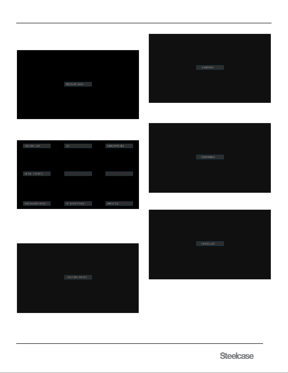
7.1.7 Reset Menu
Apply power while holding the bezel power button down until
“RELEASE NOW” text appears on display 1.
Release bezel power button to see OSD. Enter password using PUCK
#1 icons. Password is: 1342. Menu set mode enables user to configure
password reset*, IP address settings, and input equalization.
*Password reset option: not implemented
Factory Reset
Factory reset will reset every configurable setting to factory default. To
set configurations back to factory default, press and hold the power
button on the bezel. Keep holding it while the OSD is present for about
20 seconds longer.
Once this screen is visible on display 1, let go of the power button.
Prompting the switcher to confirm for a factory reset to factory defaults
on all configurable settings.
By pressing the power button once it will initiate the factory reset. Display
1 will acknowledge the confirmation with feedback as seen below and go
blank for a second as the switcher resets to factory defaults.
If the confirmation is not done within 2 seconds, the option to factory
reset will go away and switcher will not be reset to factory condition.
Page 17
media:scape® Technology Manual
400-0571-012 17
Americas Tech Support: PHONE: 1.800.334.4922 / EMAIL: [email protected]
EMEA Tech Support: PHONE: +33 3 88 13 36 36 / EMAIL: [email protected]
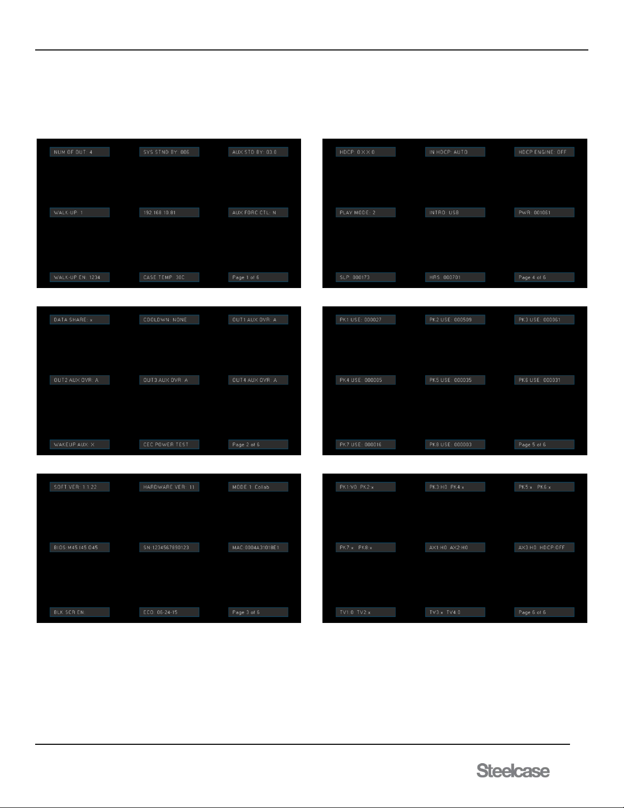
Factory Defaults
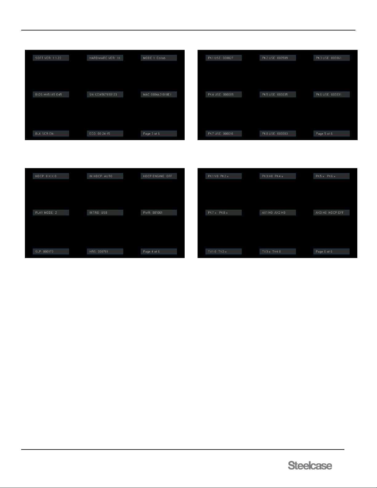
Initializing the media:scape to factory defaults results in the 6 page OSD
default values shown here. Note that the OSD displays both
configuration settings and status readings like software version, serial
number, IP address. These are not reset.
PAGE 1:
PAGE 2:
PAGE 3:
PAGE 4:
PAGE 5:
PAGE 6:
Page 18
media:scape® Technology Manual
400-0571-012 18
Americas Tech Support: PHONE: 1.800.334.4922 / EMAIL: [email protected]
EMEA Tech Support: PHONE: +33 3 88 13 36 36 / EMAIL: [email protected]
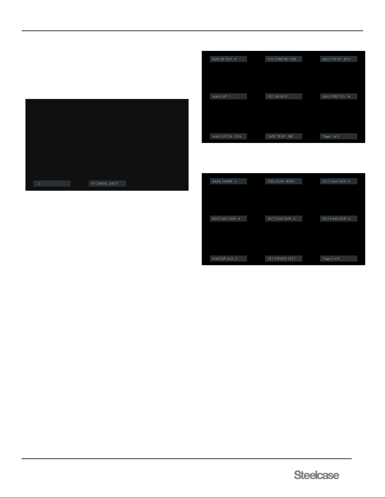
IP Configuration (Reset Menu)
In the Reset Menu, pressing 2 or 4 icons cycles through the password,
DHCP, and input equalization option. Pressing 1 or 3 when a property
is displayed changes that property. For example, IP addressing can be
set to a fixed IP address or one set by the network DHCP server.
Pressing 1 or 3 will switch between DCHP and a fixed IP address.
Pressing 2 or 4 icons will move onto another setting. To finalize the
configuration, press the power button on the bezel.
7.1.8 Wake-Up Mode
The switcher exits standby when a source signal is connected to a
PUCK or the power button on the bezel is pressed. Once activated, the
system will resume normal operation by enabling an icon on a PUCK.
The switcher can also be configured to walk up when an AUX source is
applied to Input 9, 10, or 11, thus eliminating the need to provide an
input to one of the PUCKs.
7.1.9 The Power Button on the Bezel
If the media:scape does not have any active signals applied, the power
button resets the standby mode timer and plays the introduction video
followed by the static image. When the timer expires, the switcher goes
into standby mode. The LED on the switch is white when the system is
in standby mode and green during normal operation. The power button
is located on the PUCK well, and connects through a DB9 connector on
the switcher.
Other Uses of the Power Button:
The switcher can be placed into upgrade mode for firmware upgrades
by pressing the power button 5 times rapidly. At this time the switcher
stops responding to normal operation and is waiting for the upgrade to
start. A message is displayed on the monitor to indicate upgrade mode.
FIRMWARE UPGRADE
The switcher’s on-screen display can be activated by pressing and
holding the power button for approximately 5 seconds. This is put into
detail in the following section.
7.1.9.1 On Screen Display
The switcher’s on-screen display can be activated by pressing and
holding the power button for approximately 5 seconds.
The following fields will be used to display information on 6 separate
pages. Pages can be traversed in ascending or descending order. To
navigate between pages, use icons 2 and 4 on the illuminated PUCK in
input 1. Pressing icons 1 and 3 will initiate password sequence.
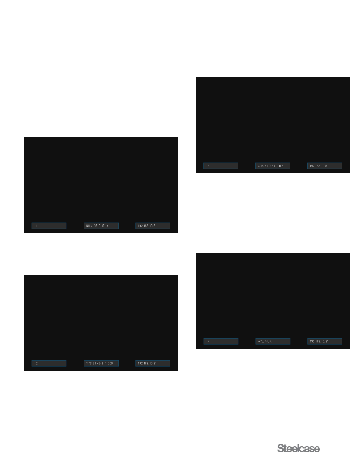
PAGE 1:
Page 1 is crucial information such as the number of outputs, AUX and
system stand by configurable information, the current IP address, and
unit temperature in Celsius.
PAGE 2:
Page 2 is information related to the AUX inputs overriding the Outputs
when no signal is present through a PUCK, Data share enabled on the
outputs as well as the CEC power test over the CEC command line.
Page 19
media:scape® Technology Manual
400-0571-012 19
Americas Tech Support: PHONE: 1.800.334.4922 / EMAIL: [email protected]
EMEA Tech Support: PHONE: +33 3 88 13 36 36 / EMAIL: [email protected]
PAGE 3:
Page 3 has information related to the software and hardware versions
as well as the latest ECO change notice. The page includes the version
number of the input, output, and main interface.
PAGE 4:
Page 4 is vital information related to the switcher such as Walk Up
Experience type, HDCP related information, statistical data such as
power (PWR) cycles, Sleep (SLP) cycles, and active/awake hours
(HRS).
PAGE 5:
Page 5 is statistical counters for each time a PUCK is connected to a
source. These PUCK connections can be reset by using the command
[PKRSTn] where n is the corresponding PUCK.
PAGE 6:
Page 6 is a diagnostics page that has information such as PUCK type
for each individual PUCK input as well as signal present. For PUCK
type, V is VGA, H is for HDMI, and D is Display Port. The Numerical
value next to it is if signal is present, x being no PUCK connected, 1
being PUCK is selected, and 0 being not selected. Same values
correspond for AUX inputs and Outputs.
Page 20
media:scape® Technology Manual
400-0571-012 20
Americas Tech Support: PHONE: 1.800.334.4922 / EMAIL: [email protected]
EMEA Tech Support: PHONE: +33 3 88 13 36 36 / EMAIL: [email protected]
7.1.9.2 On Screen Display (OSD) for basic programming
Primary configuration for media:scape can be accomplished using
OSD. To enter configuration mode, press and hold power button for
approximately 5 seconds. After that OSD will display the current status
of the switcher. In this mode, only PUCK 1 will light up. To enter
configuration mode, user needs to enter password: 1342. The PUCK
will flash and unit will be ready for configuration. From here there are a
total of 19 fields that can changed be either through the OSD or TCP
format. Keys 1 and 3 are used to move between fields
Keys 2 and 4 are used to change setting value for that particular
setting.
Configurable Field 1: NUM OF OUTS (Number of Outputs): Same as
[SMOD] command. Sets number of monitors (1-4) connected to
media:scape and also determines the number of illuminated icons on
the PUCKs.
Configurable Field 2: SYS STND BY: Same as [STBM] command but
now configured in minute intervals up to 3 hours. The standby mode is
how long the switcher displays the walk up experience or AUX inputs
before shutting down the media:scape after all (sources) are removed
from the inputs
Configurable Field 3: AUX STD BY: Same as [SSDM] command. Set
the AUX input standby time up to 12 hrs. in 30 min intervals. The AUX
standby mode is how long the switcher displays the walkup experience
before shutting down after all PUCK inputs are removed except for
when AUX inputs are present.
Configurable field 4: WALK-UP: Same as [WLKx] command.
Select the default Walk-Up experience for media:scape. Walk up
experience 1 is the default.
Option number (x = # from 1-8)
1 = still #4 plus movie #2 (default)
2 = still #5 plus movie #1
3 = still #6 plus movie #3
4 = still #4 only - no movie
5 = still #5 only - no movie
6 = still #6 only - no movie
7 = still #9 plus movie #8
8 = still #9 only - no movie
Page 21
media:scape® Technology Manual
400-0571-012 21
Americas Tech Support: PHONE: 1.800.334.4922 / EMAIL: [email protected]
EMEA Tech Support: PHONE: +33 3 88 13 36 36 / EMAIL: [email protected]
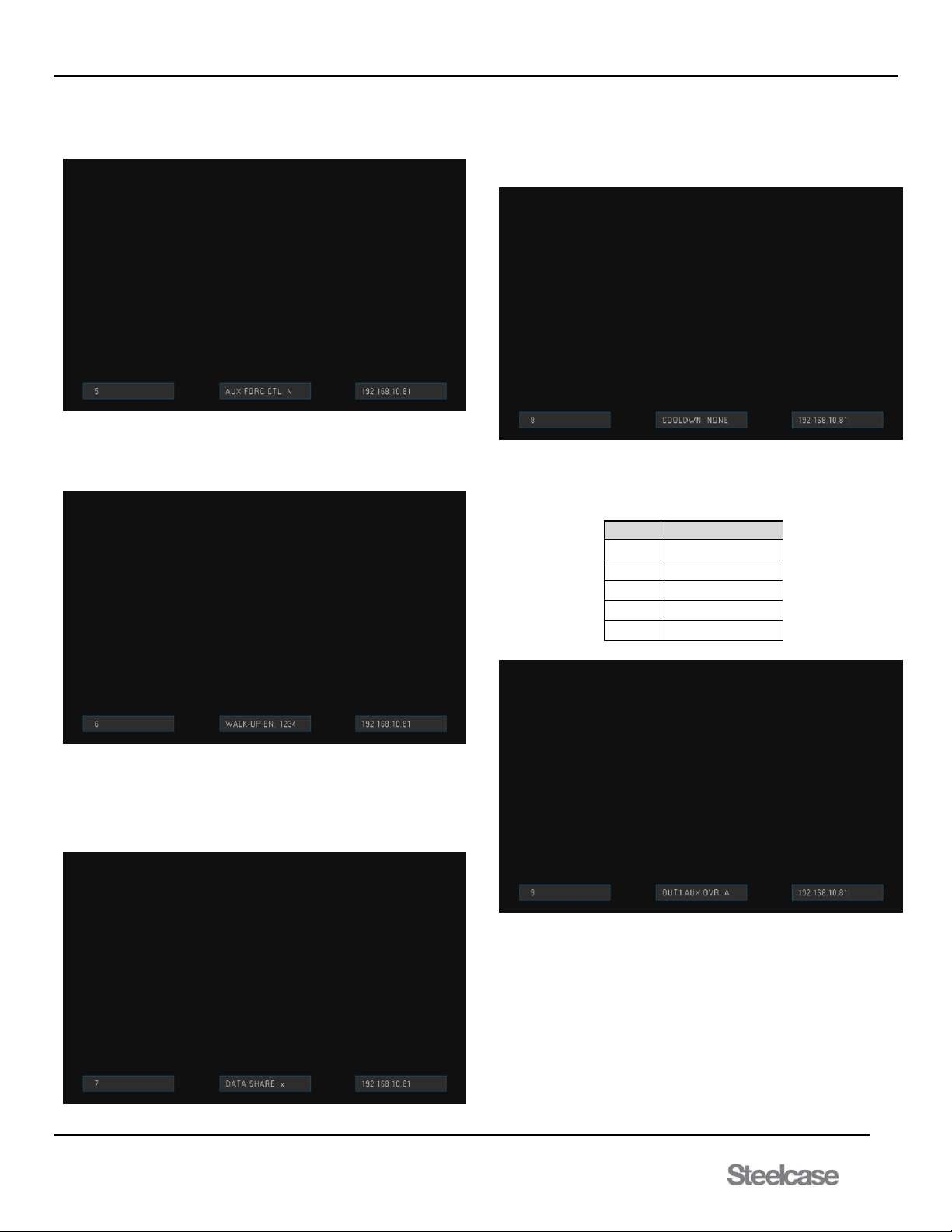
Configurable field 5: AUX FORC CTL: Choice between Yes or No of
whether AUX input can override the walk up experience on the outputs.
Configurable field 6: WALK-UP EN: configured with [SMAxxxx]
command. Displays outputs with walk up experience enabled. Example
below shows all outputs have the walk up experience enabled
Configurable field 7: DATA SHARE: Configured using [PDOx]
command. Displays outputs set for data sharing. X = none, A = All, and
# for each output enabled for data sharing. This field is dependent on
the first configurable field. For example, Outputs 2, 3, and 4 can be
configured for data share option if the number of outputs is set to 1.
Configurable field 8: COOLDWN: Same as [SOxCDy] command. Set
the cool down time for projectors. This delay allows for the outputs to be
turned off for up to 15 minutes configurable with 15 second intervals
allowing the projector to cool down.
Configurable field 9: OUT1 AUX OVR: Output can be overwritten by
either, any or none of the AUX inputs. Configured through [PIxOy], and
in this case for Output 1.
Option
Description
1
Input 9
2
Input 10
3
Input 11
X
None
A
Any AUX input
Page 22
media:scape® Technology Manual
400-0571-012 22
Americas Tech Support: PHONE: 1.800.334.4922 / EMAIL: [email protected]
EMEA Tech Support: PHONE: +33 3 88 13 36 36 / EMAIL: [email protected]
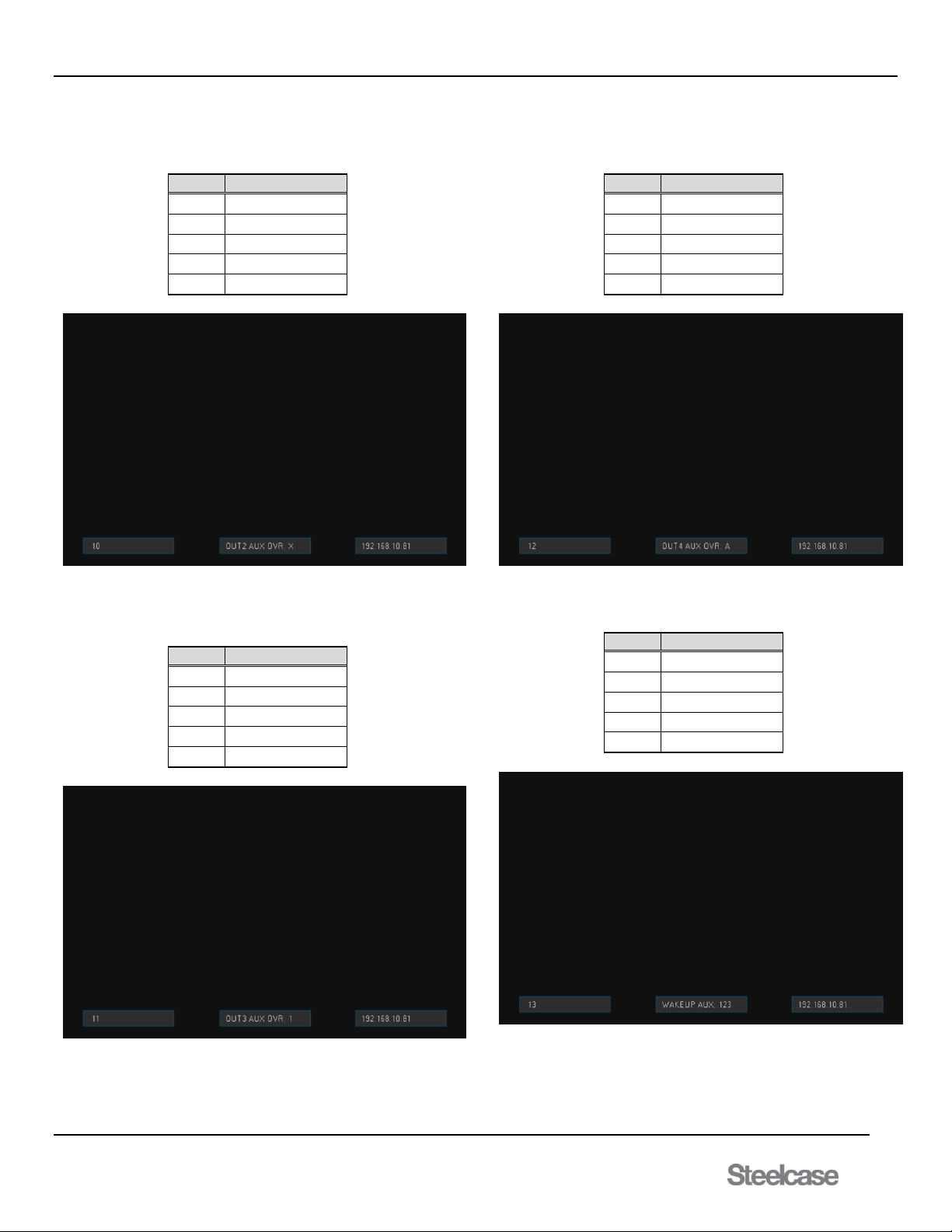
Configurable field 10: OUT2 AUX OVR: Output can be overwritten by
either, any or none of the AUX inputs. Configured through [PIxOy], and
in this case for Output 2.
Option
Description
1
Input 9
2
Input 10
3
Input 11
X
None
A
Any AUX input
Configurable field 11: OUT3 AUX OVR: Output can be overwritten by
either, any or none of the AUX inputs. Configured through [PIxOy], and
in this case for Output 3.
Option
Description
1
Input 9
2
Input 10
3
Input 11
X
None
A
Any AUX input
Configurable field 12: OUT4 AUX OVR: Output can be overwritten by
either, any or none of the AUX inputs. Configured through [PIxOy], and
in this case for Output 4.
Option
Description
1
Input 9
2
Input 10
3
Input 11
X
None
A
Any AUX input
Configurable field 13: WAKEUP AUX: Waking up media:scape
system by either, any, or none of the AUX inputs.
Option
Description
1
Input 9
2
Input 10
3
Input 11
X
None
A
Any AUX input
Page 23
media:scape® Technology Manual
400-0571-012 23
Americas Tech Support: PHONE: 1.800.334.4922 / EMAIL: [email protected]
EMEA Tech Support: PHONE: +33 3 88 13 36 36 / EMAIL: [email protected]
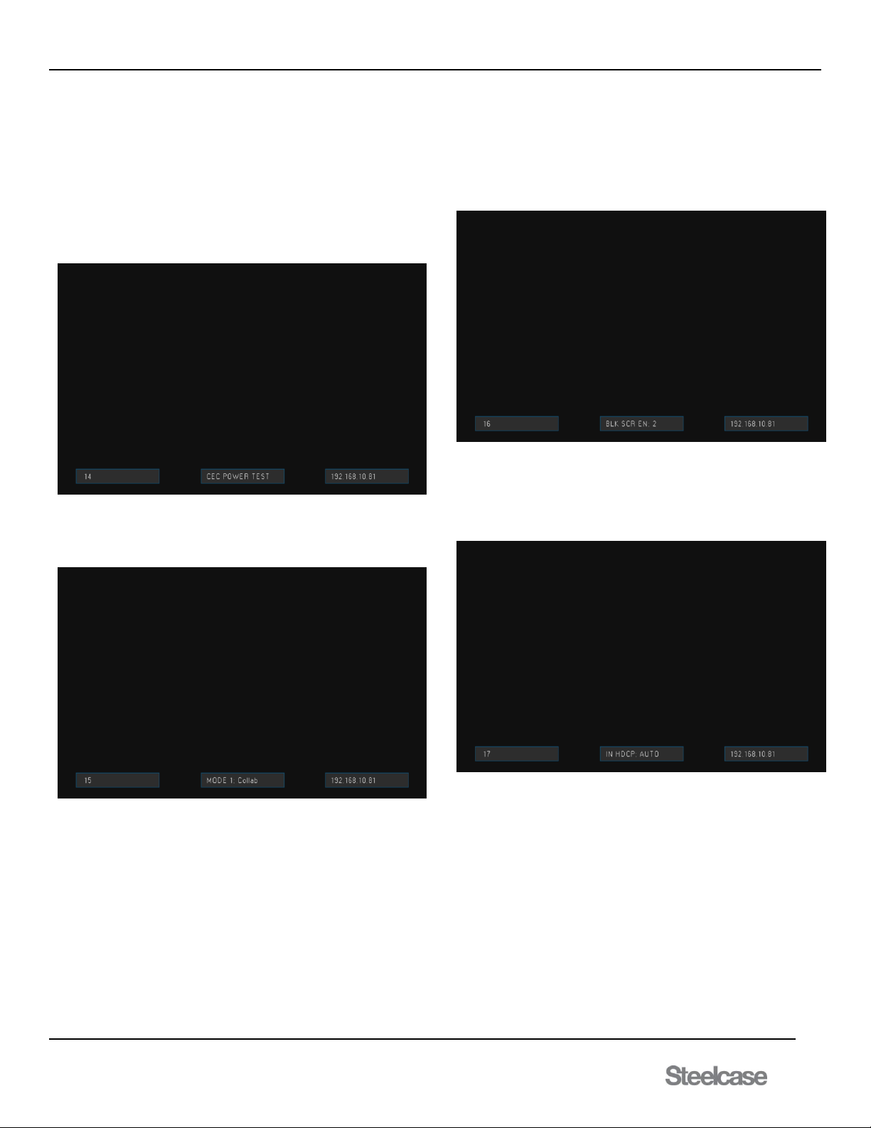
Configurable field 14: CEC POWER TEST: The use of the #2 and #4
icons can be used to determine if a display is a CEC enabled device.
Press once to turn off display, and press again to turn back on.
Only outputs not defined for monitors may be selected. For example, in
a 2 monitor system, outputs 1 and 2 are always enabled. Outputs 3 and
4 can be enabled or disabled. The CEC on command is sent when the
output is enabled after being disabled.
The output scalar must be set for INTR (interrupt) mode for the video to
also be disabled on the output of the scalar.
Configurable field 15: MODE 1: Same as [SMCp] command and it
configures between control mode and collaborative mode for the
switcher.
Configurable field 16: BLK SCR EN: configured with [SMBxxxx]
command to set the output numbers with black screen enabled. This
command works along with the [SMAxxxx] command. If the media
player output is disabled, the black screen will play in place of the
media player. If the black screen is disabled and the media player is
disabled, the output video is turned off when PUCK or AUX video is not
present on the output.
Configurable field 17: IN HDCP: Same as [HDCPx]. Setting this
configuration to ON will enable the inputs to be presented with digital
content protection. Setting it to off will disable the digital content
protection. The setting for AUTO will choose between
disabling/enabling HDCP based on the sink device for that output.
Page 24
media:scape® Technology Manual
400-0571-012 24
Americas Tech Support: PHONE: 1.800.334.4922 / EMAIL: [email protected]
EMEA Tech Support: PHONE: +33 3 88 13 36 36 / EMAIL: [email protected]
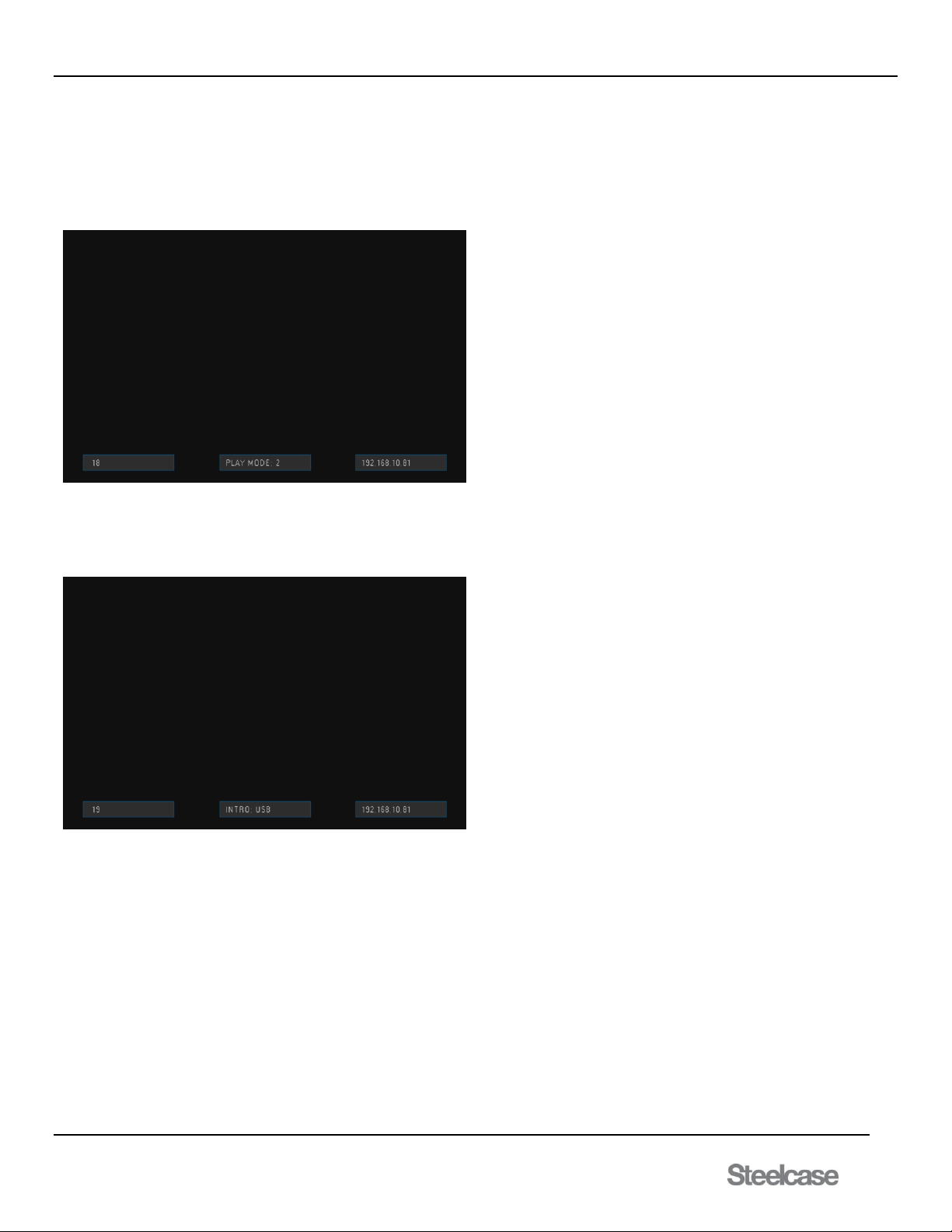
Configurable field 18: WALK UP EXPERIENCE PLAY TIME: Same as
[WUPLAYxx]. This field configures the Walk Up Experience movie play
time by looping the movie track for a prolonged period of time. Two
preset modes are given, Mode 1 sets the track to loop at 19s and Mode
2 sets to loop the selected track at 39s. Starting at 10s and
incrementing by 2s all the way to 90s can be set to loop the Walk Up
Experience.
Configurable field 19: WALK UP EXPERIENCE TYPE: Same as
[WLKUPx] Configures the Walk Up Experience type by setting it to 4
different types; USB, Video, still, or an OSD message stating
“MEDIA:SCAPE.”
After configuration, press the power button for system to enter normal
operation. If nothing is pressed while in the configurable OSD, the
system will enter normal operation within 3 minutes
Page 25
media:scape® Technology Manual
400-0571-012 25
Americas Tech Support: PHONE: 1.800.334.4922 / EMAIL: [email protected]
EMEA Tech Support: PHONE: +33 3 88 13 36 36 / EMAIL: [email protected]
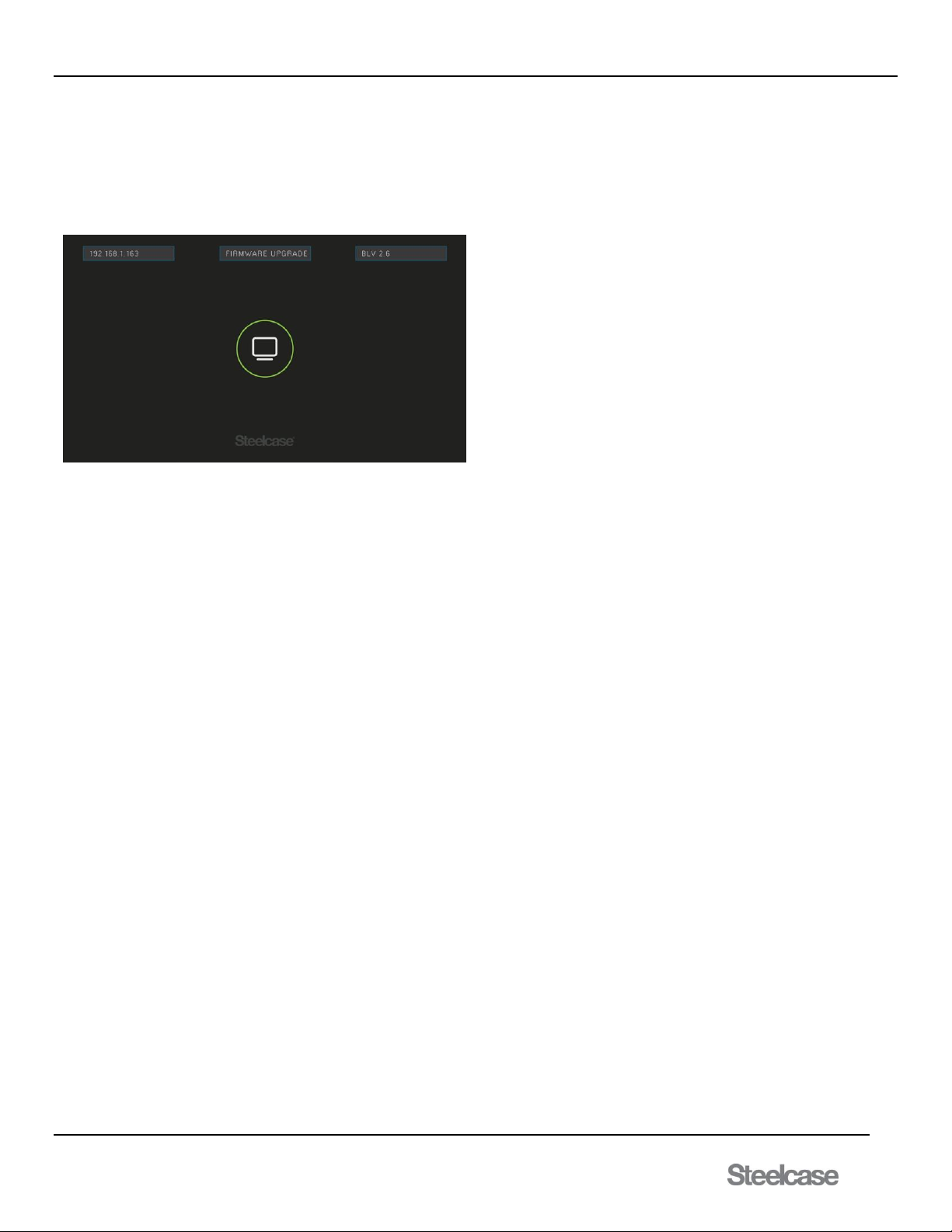
7.1.9.3 Upgrade Mode
The switcher can be only be placed into upgrade mode using special
upgrade software. At this time the switcher stops responding to normal
operation and is waiting for the upgrade to start. A message is
displayed on the monitor to indicate upgrade mode.
FIRMWARE UPGRADE
Warnings: If activated by accident, simply reset power to the switcher
to return to normal operation. However, once the upload of new
firmware is initiated, NEVER interrupt the upgrade process once it has
been started; always allow the upgrade to finish.
The default IP address of each switcher is 192.168.10.81, port 23. User
MUST assign a unique IP to each switcher before connecting to your
network or use a cross over network cable between PC and switcher.
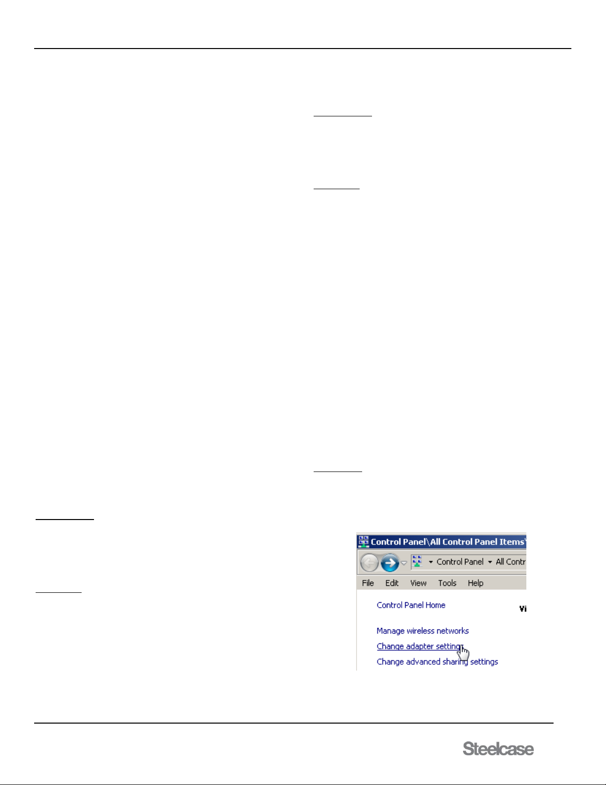
User MUST disable any unused networks on the PC before upgrading
the firmware. Open the Network and Sharing Center and use the
change adapter settings tool to view and disable unused networks. The
complete upgrade mode can be found in section 7.4
7.2 Control Mode
In control mode, users become observers as the PUCK touch surfaces
are disabled and the media:scape system is RS-232 controlled using a
third party control device. In this mode, the switcher becomes a straight
12x4 matrix switcher and the control device directs the switching among
PUCKs, AUX inputs, and the Walk up experience. The PUCKs provide
inputs 1-8, the AUX inputs 9, 10, and 11 and the Walk up experience
input 12.
PUCK icons are illuminated in response to the control device switching
just as if users make PUCK selections. In this mode the center "Off" icon
is not displayed, thus distinguishing it from the normal collaborative
mode. The PUCK makes a "click" sound if the center location is pressed
but does not respond to the press; all other icons are ignored completely.
Control mode is a temporary setting only. Every time the system goes to
standby, control mode is disabled.
In control mode any input can be connected to any output; there is no
data sharing, there are no AUX presets, and there is no auto-shutdown.
7.2.1 Upon Entering Control Mode
No I/O switching takes
Output icons do change color; status remains
“Off” icon turns off on all PUCKs
PUCKs with no input are white ring only
7.2.2 During Control Mode
Only center “Off” button clicks but no effect
PUCK icons respond to switching
If PUCK input is applied to unused PUCK, its icons turn on to
match switcher configuration (1 monitor, 2monitors, etc.)
If PUCK input is removed (signal lost), it goes to white ring
only
7.2.3 Exiting Control Mode
Control Mode is disabled when entering Standby
[SMC1] cancels Control Mode
7.2.4 Single, Dual, Triple, and Quad Systems
Control mode does not change the monitor system settings, even though
all inputs and outputs are controlled individually. For example, in a single
monitor system, switching Input 1 to Output 1 in control mode makes a
single switch only whereas in collaborative mode, pressing icon 1 on a
PUCK directs that PUCK's image to all 4 outputs.
Important: Single, dual, and triple monitor systems do not illuminate
all PUCK icons, but control mode allows independent
switching of any input to any output. Reset output states
upon exiting control mode by connecting Input 12 to all
outputs using the "[I12O*]" command; this displays the
walk up experience image on all outputs and syncs the
PUCKs with the displayed outputs.
The “Off” Icon
Control Mode - the “Off” is turned off
Control Mode - the “Off” clicks indicating Control Mode
If PUCK is not connected when the system is configured, it
does not exist. If a PUCK is added and the system is not
configured, the “Off” icons is illuminated only; no ring and no
other icons.
Page 26
media:scape® Technology Manual
400-0571-012 26
Americas Tech Support: PHONE: 1.800.334.4922 / EMAIL: [email protected]
EMEA Tech Support: PHONE: +33 3 88 13 36 36 / EMAIL: [email protected]
7.3 Monitor System Modes
The switcher can be set as a single, dual, triple, or quad monitor system
with special functions for AUX inputs. If an external video signal (PUCK
or AUX input) is not being routed to an output on the switcher, the
switcher displays the Walk up experience still image on the unused
output, unless an AUX input has been preset to display on that output.
The AUX inputs can be preset to display on any combination of the 4
outputs in all modes with Output 1 the default for both Input 9 and
Input 10. The priorities for displaying output images are as follows:
1st PUCKs ......................... Up to 8 total
2nd Input 10 (AUX preset) ... Set in configuration (default=Output 1)
3rd Input 9 (AUX preset) ..... Set in configuration (default=Output 1)
4th Walk up experience ...... Displays on outputs with none of above
The only time a blank screen is present on the output is when the
switcher is in standby mode. Otherwise there will always be an image
from a PUCK, AUX input, or the Walk up experience.
Single, Dual, and Triple Monitor Systems each support data sharing.
Only the Quad Monitor System does not support data sharing.
The number of icons illuminated on the PUCKs identifies the switcher's
mode of operation. The different modes illuminate the icons as follows:
Single Monitor System: Illuminates icon #1
Dual Monitor System: Illuminates icons #1 and #2
Triple Monitor System: Illuminates icons #1, #2, and #3
Quad Monitor System: Illuminates icons #1, #2, #3, and #4
WARNING: Priority mode overrides normal operation when Input 9, 10
and/or 11 have video signals present. See 7.1.3 for details.
7.3.1 Single Monitor System
In a single monitor system, only icon 1 is illuminated on the PUCKs. The
data share output can be set to any or all of Outputs 2-4 with Output 4
the default. The “Off” icon will illuminate when the allowed output is
selected.
Pressing icon 1 on a PUCK (while icon is white) directs that PUCK's
video to all 4 outputs. Pressing icon 1 a second time (while the icon is
green) removes PUCK's video from all outputs except those defined as
data sharing outputs. Pressing "Off’ removes the PUCK's video from all
outputs regardless of data sharing. The Walk up experience image is
displayed on the unused outputs unless AUX presets have been defined
and AUX inputs are present.
7.3.2 Dual Monitor System
In a dual monitor system, icons 1 and 2 are illuminated on the PUCKs.
The data share output can be set to Outputs 3, Output 4, or both Outputs
3 and 4 with Output 4 the default. The “Off” icon will illuminate when the
allowed output is selected.
No Data Sharing
Pressing icon 1 on a PUCK (while icon is white) directs that PUCK's
video to Outputs 1 & 3; icon 2 directs video to Outputs 2 & 4. Pressing
icon 1 a second time (while the icon is green) removes the PUCK's
image from Outputs 1 & 3. Pressing "Off" removes the PUCK's video
from all outputs. The Walk up experience image is displayed on any
output that does not have a PUCK image unless AUX presets have been
defined and AUX inputs are present.
Data Sharing
Pressing icon 1 on a PUCK (while icon is white) directs that PUCK's
video to Outputs 1 & 3 plus the data share output; icon 2 directs video to
Outputs 2 & 4 plus data share. The image from the last PUCK selection
is always displayed on the data share output.
Pressing the last PUCK selection, a second time (while the icon is green)
turns the icon white, leaves the outer ring green, and removes the
PUCK's image from its associated outputs except those defined as data
sharing outputs. Pressing "Off" removes the PUCK's video from all
outputs regardless of data sharing. The walk up experience image is
displayed on any output that does not have a PUCK image unless AUX
presets have been defined and AUX inputs are present.
7.3.3 Triple Monitor System
In a triple monitor system, icons 1, 2, and 3 are illuminated on the
PUCKs. The data sharing output can only be set to Output 4. The “Off”
icon will illuminate when the allowed output is selected.
No Data Sharing
Pressing icon 1 on a PUCK (while icon is white) directs that PUCK's
video to Output 1; icon 2 to Output 2, icon 3 to Output 3. Pressing an
icon a second time (while the icon is green) removes the PUCK's image
from its output. Pressing "Off" removes the PUCK's video from all
outputs. The Walk up experience image is displayed on any output that
does not have a PUCK image unless AUX presets have been defined
and AUX inputs are present.
Data Sharing
Pressing icon 1 on a PUCK (while icon is white) directs that PUCK's
video to Output 1 plus the data share output; icon 2 to Output 2 plus data
share and 3 to Output 3 plus data share. The image from the last PUCK
selection is always displayed on the data share output.
Pressing the last PUCK selection a second time (while the icon is green)
turns the icon white, leaves the outer ring green, and removes the
PUCK's image from its associated output except those defined as data
sharing outputs.
Pressing "Off" removes the PUCK's video from all outputs regardless of
data sharing. The Walk up experience image is displayed on any output
that does not have a PUCK image unless AUX presets have been
defined and AUX inputs are present.
7.3.4 Quad Monitor System
In a quad monitor system, icons 1, 2, 3, and 4 are illuminated on the
PUCKs and there is no data sharing output available. The “Off” icon will
illuminate when the allowed output is selected.
Pressing icon 1 on a PUCK (while icon is white) directs that PUCK's
video to Output 1; icon 2 to Output 2, 3 to Output 3, and 4 to Output 4.
Pressing an icon a second time (while the icon is green) removes the
PUCK's image from its output. Pressing "Off" removes the PUCK's video
from all outputs. The Walk up experience image is displayed on any
output that does not have a PUCK image unless AUX presets have been
defined and AUX inputs are present.
7.4 Before Firmware Upgrade Mode
Use the following procedures to set a unique IP address as well as
disabling any network communication other than LAN during firmware
upgrade.
Set Unique IP
Establish a TCP connection between the switcher and the laptop using a
network, crossover cable and communication software like AVSnap or
HyperTerminal.
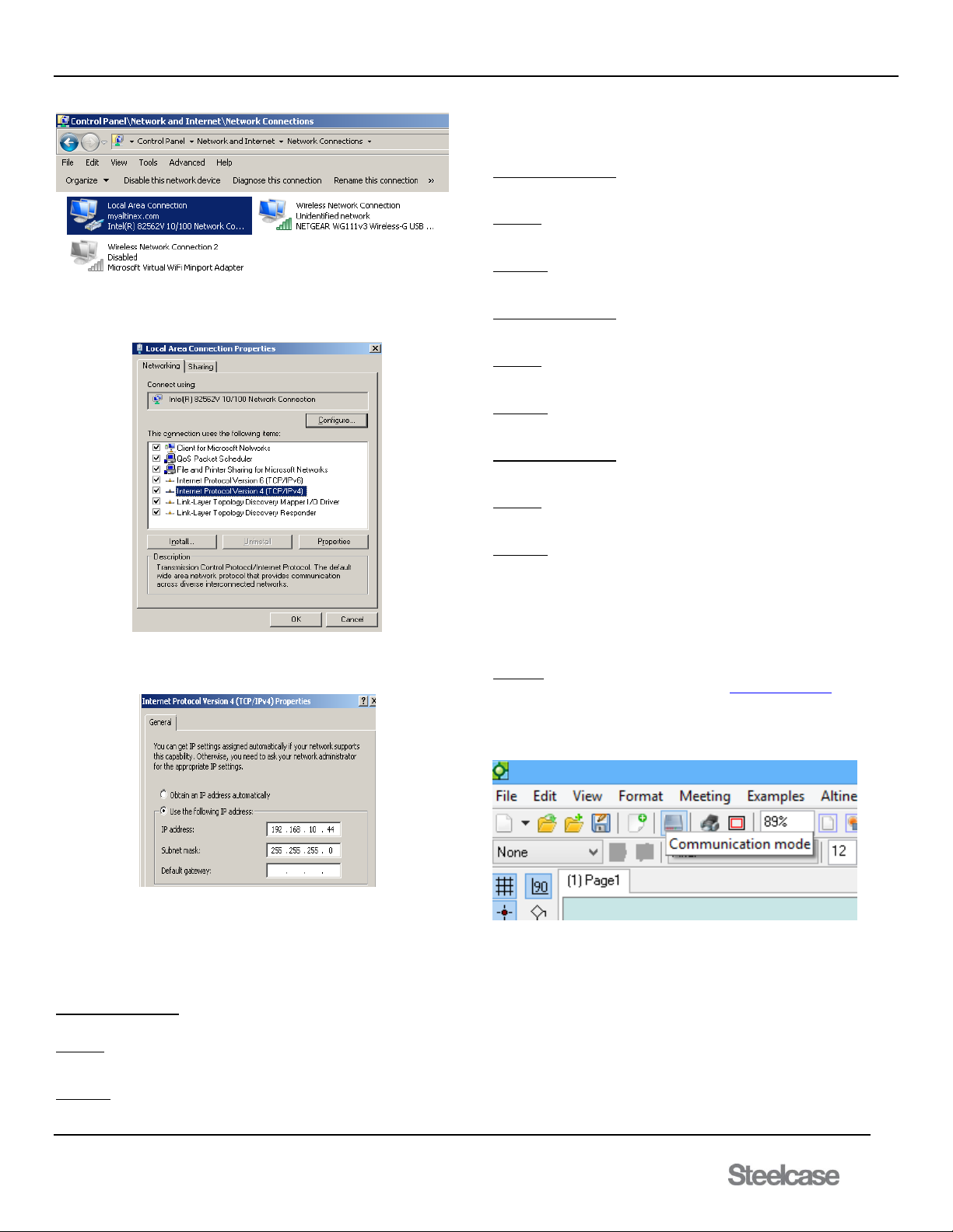
1) Set the IP address of the laptop to 192.168.10.44 using the
Change Adapter Settings tool in the Network and Sharing
Center.
2) Select the Local Area Connection properties.
Page 27
media:scape® Technology Manual
400-0571-012 27
Americas Tech Support: PHONE: 1.800.334.4922 / EMAIL: [email protected]
EMEA Tech Support: PHONE: +33 3 88 13 36 36 / EMAIL: [email protected]
3) Select the Internet Protocol Version 4 (TCP/IPv4) option and
click Properties.
4) This IP address must be on the same network as the switcher.
The default switcher IP is 192.168.10.81 so choose something
like 192.168.10.44.
5) Use AVSnap or HyperTerminal to send the commands as
described below in order to set a unique IP for your LAN. Each
command causes the TCP connection to be broken, so after
sending each command, except [CRC], you will have to
re-connect a new connection.
Command Description
1) [CRC] Read network settings
Example
[CRC]
Feedback
Returns MAC address,
IP address, PORT number,
Subnet, and Gateway
Command Description
2) [CSP] Set switcher IP address
Example
[CSP192.168.1.123]
Feedback
None, disconnects
Command Description
3) [CSB] Set switcher subnet
Example
[CSB255.255.255.0]
Feedback
None, disconnects
Command Description
4) [CSG] Set switcher gateway
Example
[CSG192.168.1.1]
Feedback
None, disconnects
The [CSP] command MUST be sent to provide a unique ID.
The subnet command and gateway commands only need to be sent if
required by your network administrator. See Section 7.5 for examples of
command lines.
AVSNAP
Download the software readily available at http://avsnap.com/. AVSNAP
is a tool that has many uses such as using block diagrams or
manufacture libraries for system design, GUI programming for user
interfaces, and RS232 communication. Once installed, run the program
and click on the communications mode button at the top.
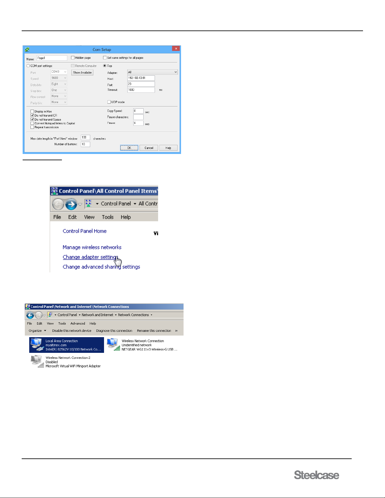
Once in communication mode, in the terminal window double click to set
up the communication between computer and media:scape. Refer to the
next section on the complete command list. Host address is the IP
address assigned earlier.
Page 28
media:scape® Technology Manual
400-0571-012 28
Americas Tech Support: PHONE: 1.800.334.4922 / EMAIL: [email protected]
EMEA Tech Support: PHONE: +33 3 88 13 36 36 / EMAIL: [email protected]
Disable Networks
1) Open the Network and Sharing Center from the Control Panel
or taskbar icon.
2) Select the Change Adapter Settings tool.
3) Disable all network connections except the Local Area
Connection properties. Click on the wireless and Bluetooth
connection and then select disable.
Page 29
media:scape® Technology Manual
400-0571-012 29
Americas Tech Support: PHONE: 1.800.334.4922 / EMAIL: [email protected]
EMEA Tech Support: PHONE: +33 3 88 13 36 36 / EMAIL: [email protected]
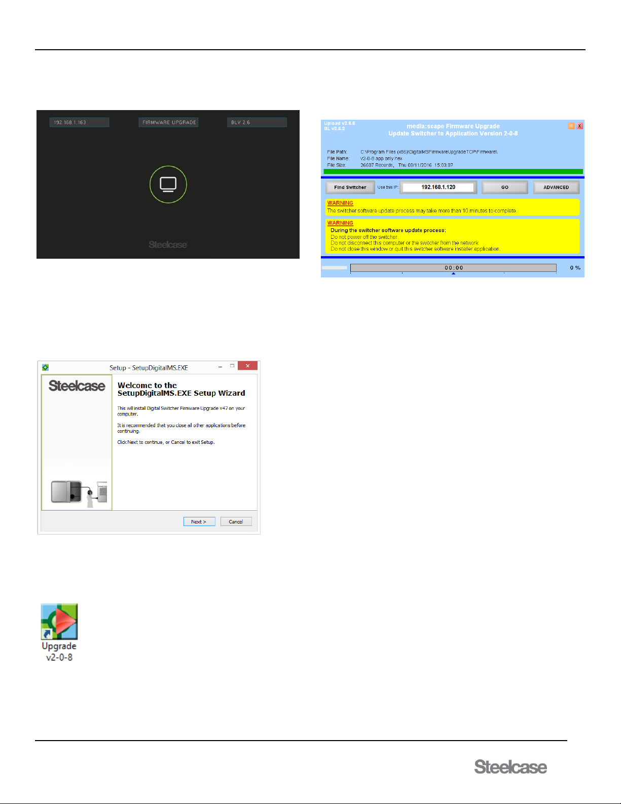
7.4.2 Entering Firmware Update Mode
This mode is entered using the upgrade software only. Once in this
mode, the media:scape displays OSD on the screen that reads as shown
with the media:scape’s IP address:
The software upgrade runs on a laptop (or over the network) that will
automatically update firmware for media:scape. PUCK in Input 1 is lit
while in FIRMWARE UPGRADE mode. Normal operation of the
media:scape is non-operational. If firmware fails, restart application
firmware, and then repower the media:scape and upload firmware. If
firmware fails, media:scape will automatically go into firmware update
mode automatically. Now that the media:scape is in upgrade mode follow
the process of upgrading to the latest firmware.
Step One: Open the update folder containing the firmware update file
and launch the EXE file. Install the software required for firmware upload.
Click Next to continue with the setup and install the upgrade application.
Step 2: Once installed, launch the application using the following
shortcut icon.
On startup, the application searches for switchers. If detected, a single
switcher IP appears in the text box in the middle of the screen. If this is
NOT the correct IP, you change it to the desired IP to upgrade.
Step 3: Now to update the media:scape. Click the GO button; the
application runs automatically from this point forward. The following
operations are performed: Erase and Program.
Step 3: After the switcher has been programmed, a success message is
displayed. If there was a problem, follow the instruction to achieve a
successful upgrade.
Step 4: Close the upgrade application
Step 5: Reset power to the media:scape.
----------------------------- Upgrade is complete ------------------------------
Page 30
media:scape® Technology Manual
400-0571-012 30
Americas Tech Support: PHONE: 1.800.334.4922 / EMAIL: [email protected]
EMEA Tech Support: PHONE: +33 3 88 13 36 36 / EMAIL: [email protected]
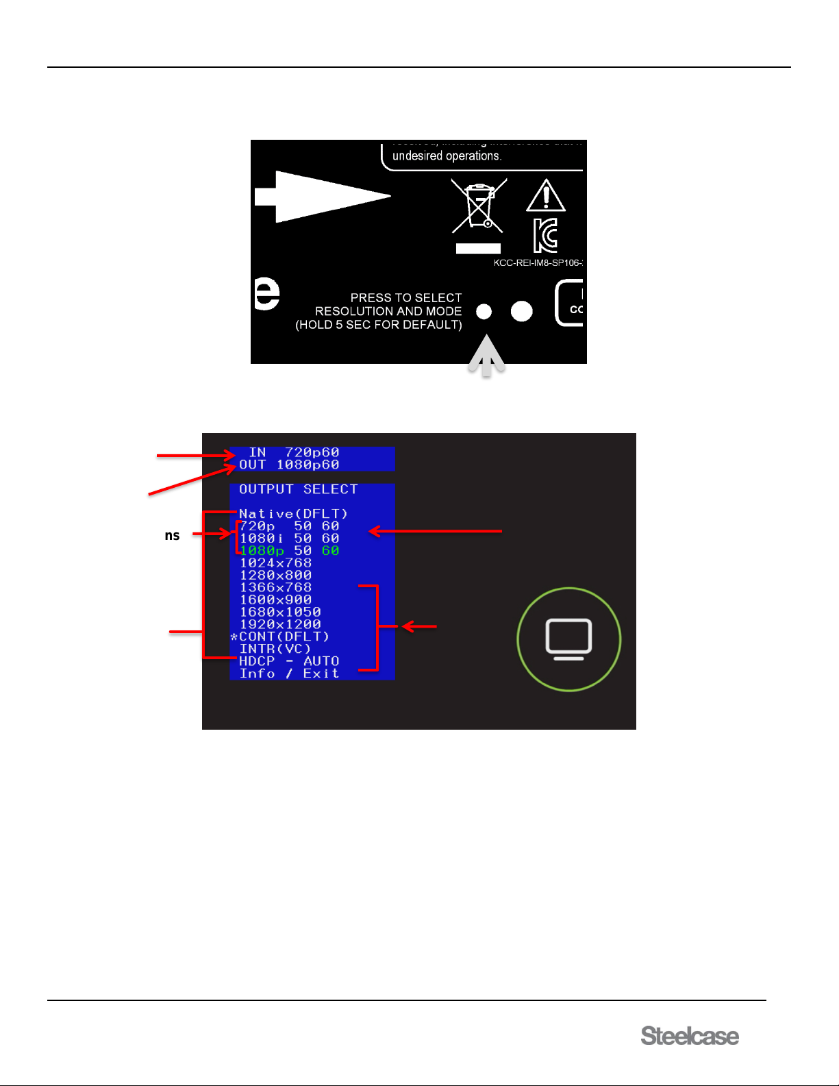
7.4.5 Installation of digital scaler (SP106-253).
Location of Resolution/Mode Button
Step 1: Connect the output of the scalar to the display
Step 2: Connect the cable from the output of the media:scape to the input of the scalar.
Step 3: Set the scaler to a known starting resolution holding down the resolution/mode button for 5 seconds and observing power led flashing 2 times.
Step 4: Use the resolution/mode button and on-screen display to make further image property changes.
How to make menu adjustments: Press resolution/mode button to show the on-screen menu. Press mode/resolution button again to move the
highlighted field to the next field. Once required resolution is selected, wait until the on-screen menu times out. That will set new property or resolution.
If Info option is selected on the OSD, then it will display latest firmware number as well as input/output details. To exit without any adjustments select the
Exit option at the bottom of the OSD menu. Once OSD times out, the scaler will return to normal operation.
Modes:
CONT: (continuous) Output generates black screen signal when the input signal is lost. This prevents display’s OSD messages from displaying.
INTR: (interrupted) Output won’t send signal out when the input signal is lost.
Input Resolution
Output Resolution
HD Output Resolutions
PC output
resolutions
Match output of
scaler to
display’s native
resolution
Output Resolution
Page 31
media:scape® Technology Manual
400-0571-012 31
Americas Tech Support: PHONE: 1.800.334.4922 / EMAIL: [email protected]
EMEA Tech Support: PHONE: +33 3 88 13 36 36 / EMAIL: [email protected]
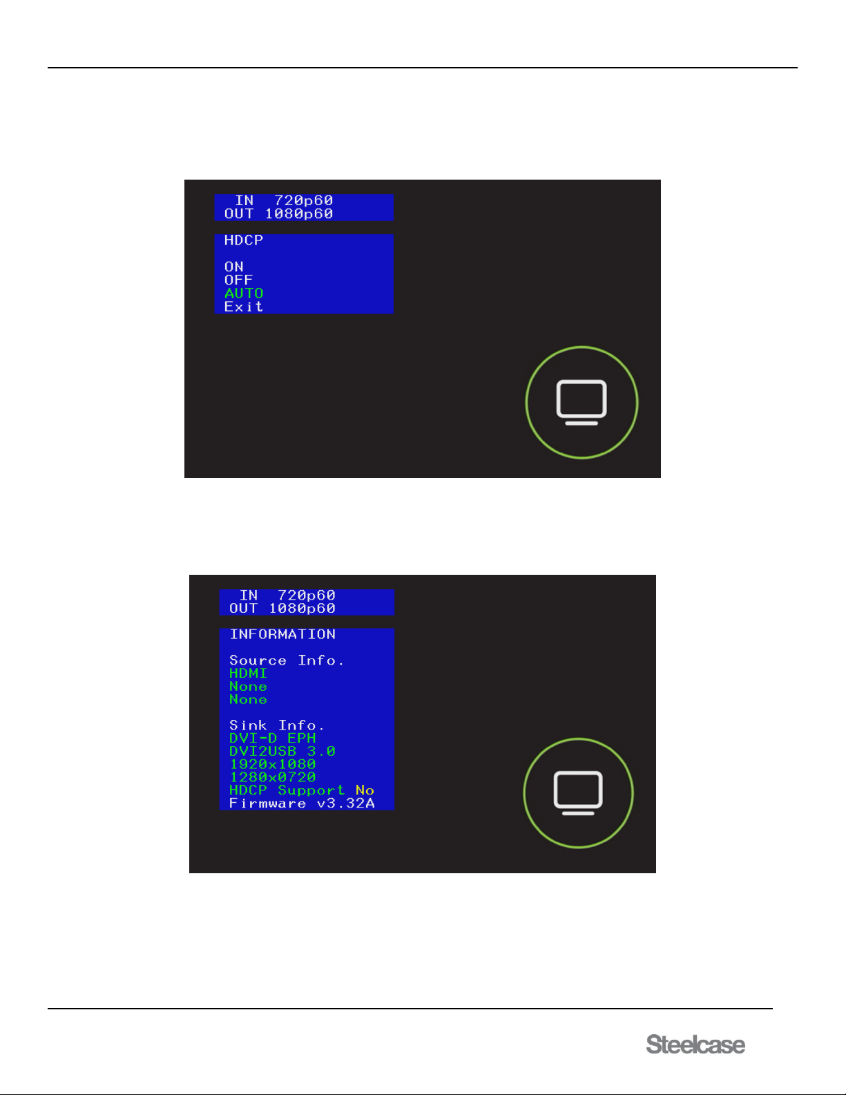
HDCP Option
Selecting HDCP from the main menu pulls up the HDCP submenu. Press the resolution/mode button to until the desired mode is highlighted.
ON The scaler passes HDCP protected content
OFF The scaler passes Non-HDCP content and blocks HDCP protected content.
AUTO The scaler mirrors the HDCP capability of the sink device.
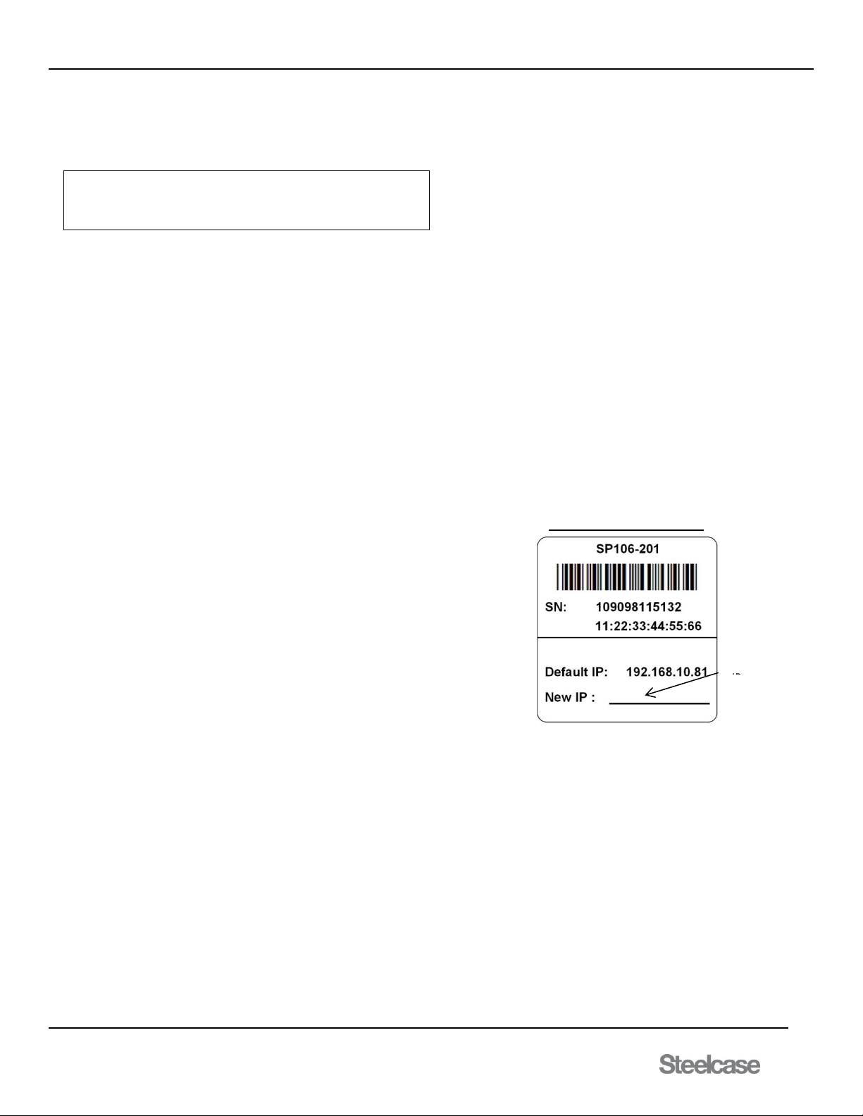
Info
Displays additional scaler information including: incoming resolution, output resolution, source information, sink information, and the unit firmware
version
Reset
Press and hold resolution/mode button for 5 seconds to set to factory settings. Power LED will flash two times. If power LED does not flash, the scaler
did not reset.
Page 32

media:scape® Technology Manual
400-0571-012 32
Americas Tech Support: PHONE: 1.800.334.4922 / EMAIL: [email protected]
EMEA Tech Support: PHONE: +33 3 88 13 36 36 / EMAIL: [email protected]
System Operation with Scaler
PASS The Media:scape switcher enables the HDCP engine. Sources are able to output protected content. If a non-HDCP sink is used, the scalar
displays the “Protected Content” message. This option can be used to display fully protected content, but only to HDCP sinks. Non-HDCP
sinks only display the error message.
BLOCK The Media:scape switcher disables the HDCP engine. Sources only output unprotected content. Depending on the source, this may create
confusion as in the examples below.
Blu-ray If the HDCP engine is OFF, video output is a black screen and NOT protected. This condition cannot be detected since
the screen is black. There is no way to detect this condition and for the scaler to display an error message.
MacBook If the HDCP engine is OFF, no protected content is displayed. The MacBook will provide the desktop image but not
protected video. For example, a movie playing in iTunes stops playing and the image inside the iTunes window goes
black. The window and desktop are still visible.
AUTO The scaler mirrors the HDCP capability of the sink device. This option lets the Media:scape switcher read the HDCP capability of the sink. If
a Non-HDCP sink is detected, the HDCP engine is turned off and sources do not provide protected content. AUTO is the default setting.
System Operation without Scaler
HDCP Engine ON This option forces the Media:scape switcher HDCP engine to always be enabled. Sources can provide protected content. The
“PROTECTED” message is displayed on Non-HDCP sinks.
HDCP Engine OFF This option forces the Media:scape switcher HDCP engine to always be disabled. No protected content is provided by source.
Blu-ray If the HDCP engine is OFF, video output is a black screen and NOT protected. This condition cannot be detected since
the screen is black. There is no way to detect this condition and for the scaler to display an error message.
MacBook If the HDCP engine is OFF, no protected content is displayed. The MacBook will provide the desktop image but not
protected video. For example, a movie playing in iTunes stops playing and the image inside the iTunes window goes
black. The window and desktop are still visible.
HDCP Auto The Media:scape switcher reads the HDCP capability of the sinks connected to the outputs. If any sinks are Non-HDCP, the
HDCP engine is disabled; otherwise the HDCP engine is enabled.
Page 33
media:scape® Technology Manual
400-0571-012 33
Americas Tech Support: PHONE: 1.800.334.4922 / EMAIL: [email protected]
EMEA Tech Support: PHONE: +33 3 88 13 36 36 / EMAIL: [email protected]
7.5 TCP/IP Control
The control commands for the media;scape are in a simple ASCII
character format. Commands are software V.49 compatible. Commands
are compatible with both the 8x4 and 4x2 digital switcher.
1. Square brackets "[ ]" are part of the command.
2. Use uppercase letters for all commands.
3. Spaces are not legal characters.
1. [ACTIVE]
This command returns the running mode of the M:S. The M:S returns
[APP] if the normal application is running or [BL] if in bootloader more.
2. [AUTH]
Force M:S to authenticate all outputs. This is an execute command
Command Format: [AUTH]
Example: [AUTH] command will force switcher to check all outputs to
see if they are HDCP compliant destinations.
3. [BLV]
This command returns the bootloader version installed on the switcher.
The bootloader must have been run for the main application to know
the current bootloader more.
4. [BLS]
This command returns the IP addresses and status of the last
bootloader run. The first IP is the IP of the main application upon
entering bootloader mode and the second is the IP used in the
bootloader, and the final number displayed is the status.
[192.168.1.163,192.168.1.163,2]
Status Values
0=Bootloader ran normally
1=Bootloader IP did not match application IP
2=Bootloader was cancelled before erase operation
3=Bootloader timeout occurred before erase operation
5. [BLS+]
This command is the same as the [BLS] command, but includes text
descriptions.
6. [CECx]
Verification of CEC enabled device on all outputs. If destination device is
not responsive it is not rated for this HDMI specific feature.
Command Format: [CECx]
(0=TV off, 1=TV on)
Example:
[CEC1] will turn on all TVs while [CEC0] turns off all TVs Media:scape
will return [] after execution of command regardless if TV is CEC
enabled.
7. [CRC]
Read the complete TCP/IP configuration of the controller that is currently
in use on the network.
TCP Feedback: [SRC,SCShsa,i,p,s,g,m]
Command Format: [CRC]
h = Hardware Version
s = Software Version
a = Alias ID (00000) * Not Implemented
i = Static IP (4 octets)
p = Port (decimal value from 1 to 65535)
s = Subnet (4 octets)
g = Gateway (4 octets)
m = Mac Address (12 hex characters)
Example:
A Controller has the following settings:
Property Value
Hardware Version 00
Software Version 47
Alias ID (00000) * Not Implemented
Static IP: 192.168.1.218
Port: 23
Subnet: 255.255.255.0
Gateway: 192.168.1.254
Mac Address (fixed): 00-04-A3-1D-28
Read the settings for the controller by sending the following:
[CRC]
The media:scape returns the following feedback:
TCP:
[SRC,SCS004700000,192.168.1.218,23,255.255.255.0,192.168.1.25
4,00-04-A3-10-1D-28]
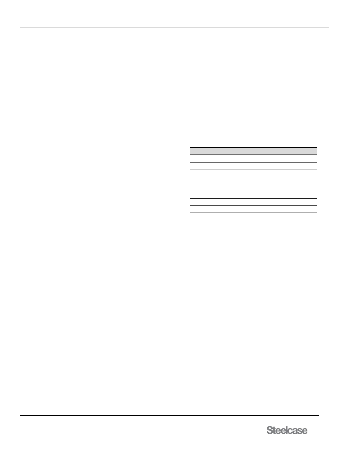
Important: Write the new IP address and port number on the label
provided on the bottom of the unit. It will be needed to
identify the unit.
Permanently identify the unit
Important: Write this new IP address on the label provided on the
bottom of the unit. It will be needed to identify the unit.
8. [CRC+]
Same as [CRC], except it displays the saved (an/or changed) settings
that take effect after reset of the switcher. Command to read the
complete TCP/IP configuration of the controller
Command Format: [CRC+]
Example:
Verify the settings are correct by sending the following command.
[CRC+]
Write in the
new static
Page 34

media:scape® Technology Manual
400-0571-012 34
Americas Tech Support: PHONE: 1.800.334.4922 / EMAIL: [email protected]
EMEA Tech Support: PHONE: +33 3 88 13 36 36 / EMAIL: [email protected]
9. [CSB]
Set the subnet of the controller. The subnet should be provided by your
IT administrator. The switcher does not send a confirmation after
changing the subnet mask, but it does break the TCP/IP connection. A
new connection must be established after changing.
Command Format: [CSBddd.ddd.ddd.ddd]
ddd = Subnet address (4 octets, 001 to 255)
Example:
Set the controller subnet to 255.255.255.0 by sending the following:
TCP: [CSB255.255.255.0]
10. [CSB+]
Same as [CSB], except the changes do not take effect until after reset of
the switcher. Set the subnet of the controller. The subnet should be
provided by your IT administrator. The switcher does not send a
confirmation after changing the subnet mask, but it does break the
TCP/IP connection. A new connection must be established after
changing.
Command Format: [CSB+ddd.ddd.ddd.ddd]
ddd= Subnet address (4 octets, 001 to 255)
Example:
Set the controller subnet to 255.255.255.0 after the reset by sending the
following:
[CSB+255.255.255.0] will return feedback as follows: [255.255.255.0]
11. [CSG]
Set the gateway of the controller. The gateway should be provided by
your IT administrator. The Switcher does not send a confirmation after
changing the gateway, but it does break the TCP/IP connection. A new
connection must be established after changing.
Command Format: [CSGddd.ddd.ddd.ddd]
ddd= Gateway address (4 octets, 001 to 255)
Example:
Set the controller gateway to 192.168.1.0 by sending the following:
TCP: [CSG192.168.1.0]
12. [CSG+]
Same as [CSG], except changes do not take effect until after the reset of
the switcher. Command to set the gateway of the controller. The
gateway should be provided by your IT administrator. The Switcher does
not send a confirmation after changing the gateway, but it does break
the TCP/IP connection. A new connection must be established after
changing.
Command Format: [CSG+ddd.ddd.ddd.ddd]
ddd= Gateway address (4 octets, 001 to 255)
Example:
Set the controller gateway to 192.168.1.0 by sending the following:
TCP: [CSG+192.168.1.0]
13. [CSN]
Set the switcher alias to be displayed in the discovery feedback.
Command Format: [CSNaaaaa]
aaa= Alias (12 alphanumeric characters plus dash)
Example:
Set the media:scape address to STEELCASE-MS by sending the
following command:
TCP: [CSNSTEELCASE-MS]
14. [CSP]
Set the static IP address of the controller for identification on the LAN.
The IP must be unique and reserved for the controller by your IT
administrator. The media:scape does not send a confirmation after
changing the IP, but it does break the TCP/IP connection. A new
connection must be established after changing.
Command Format: [CSPddd.ddd.ddd.ddd]
ddd= IP address (4 octets, 001 to 255)
Example:
Set the controller IP address to 10.200.2.100 by sending the following:
TCP: [CSP10.200.2.100]
15. [CSP+]
Same as [CSP], except changes do not take effect until after the reset of
the switcher. Command to set the static IP address of the controller for
identification on the LAN. The IP must be unique and reserved for the
controller by your IT administrator. The media:scape does not send a
confirmation after changing the IP, but it does break the TCP/IP
connection. A new connection must be established after changing.
Command Format: [CSP+ddd.ddd.ddd.ddd]
ddd= IP address (4 octets, 001 to 255)
Example:
Set the controller IP address to 10.200.2.100 by sending the following:
TCP: [CSP+10.200.2.100]
16. [DHCPx]
Sets up either DHCP or fixed IP address
Command Format: [DHCPx]
X = configuration protocol select
(1 = DHCP, 0 = fixed IP)
Example:
Use the command [DHCP1] to set a dynamic IP address.
17. [DRV]
This command displays current internal main BIOS, input BIOS, and
output BIOS
**Note: OSD position and size adjustment commands require minimum
version 26.8.37, 27.8.37, and 28.8.37.
Command Format: [DRV]
Example:
Entering command [DRV] will return feedback in the format
[(MAIN:26.8.37)(IN:27.8.37)(OUT:28.8.37)]
18. [FAN]
This command returns fan speed setting in percentage 00~100. The
speed indicates the calculated value based on system temperature and
is not affected by the manual [FANx] commands. The fan speed is
ramped up/down incrementally as temperature changes to avoid
sudden changes in sound.
Command Format: [FAN]
xx = 0-100, 100 fan is at full speed and 0 fan being at the slowest
speed (0 rpm).
Return format = [Fxx]
Example: Use command [FAN] to return feedback [F38] meaning that
the fan is running at 38% of maximum.
Page 35

media:scape® Technology Manual
400-0571-012 35
Americas Tech Support: PHONE: 1.800.334.4922 / EMAIL: [email protected]
EMEA Tech Support: PHONE: +33 3 88 13 36 36 / EMAIL: [email protected]
19. [FANx]
Set the fan speed on a temporary basis to verify operation (This is for
testing only). Under normal conditions, the fan only turns on when the
internal circuit board is too warm. This test fan speed only remains
active until the next automatic fan update.
Command Format: [FANx]
x = Output number (n = # from 0 to 3)
0 = Off/normal operation
1 = Half speed
2 = Full speed
3 = Max speed
Example:
Set the fan to full speed by sending:
[FAN2]
Fan test during power up process.
In order to identify that fan and fan circuit is fully operational we
implement the power up fan test. During power up fan will be turned on
for 2 seconds on medium speed and then 2 seconds for high speed and
then turned off.
20. [FXDIP]
Use fixed IP set using [CSP],[CSB],and [CSG] commands.
Command Format: [FXDIPx]
x = Configuration protocol select
(1= fixed, 0=DHCP)
Example:
Use the command [FXDIP1] to set a fixed IP address.
21. [HDCP]
Display content protection engine state
Command Format: [HDCP]
Example:
Feedback from command [HDCP] to return
[0] = HDCP ON
[1] = HDCP OFF
22. [HDCPx]
Set HDCP engine ON/OFF or AUTO
Command Format: [HDCPx]
x = configuration protocol select
0 = HDCP ON
1 = HDCP OFF
2= HDCP AUTO (Default)
Example:
Use the command [HDCP1] to set HDCP engine off. No HDCP content
will display.
23. [HDCPIx]
Display content protection of input (x = input number 1~11)
Command Format: [HDCPx]
x = input number
Feedback return:
0 = None
1 = Protected
2 = No input signal
Example:
Command [HDCPI1] will return [1] indicating that the source on input 1
has protected content.
24. [HDCPM]
Display saved status in memory of content protection engine.
Command Format: [HDCPM]
Example:
Use the command [HDCPM] to return
[0] = HDCP ON
[1] = HDCP OFF
[2] = HDCP AUTO
25. [HDCP?]
Display content protection support for outputs 1~4 in the feedback
format [(CP xx)(CP xx)(CP xx)(CP xx) when HDCP engine is set to
default
Command Format: [HDCP?]
Example: use command [HDCP?] to return:
CP OK Sink device supports content protection
CP NS Sink device does NOT support content protection
OPEN No sink device connected
CP ER Content protection status could not be determined
Feedback [(CP OK)(CP OK)(CP OK)(CP OK)] indicates that all 4
outputs have destinations that support HDCP content.
26. [HW]
Displays the hardware version of the media:scape.
Command Format: [HW]
Example:
Use the command [HW] to return: [02] (Version 2)
27. [INEQ]
This command returns the input equalization setting of the
media:scape. The return values are as follows:
0 = Default equalization
1 = Display Port PUCKs have high equalization
2 = PUCKs have high equalization
Note that the media player input is not included.
28. [INEQB]
This command returns the setting of all 11 inputs individually.
[0,0,0,0,0,0,0,0,0,0,0] = all standard equalization
[0,0,0,0,0,0,0,0,1,1,0] = Aux inputs 1 and 2 have high equalization
29. [INEQx]
This command sets the input equalization. Use a single digit to set all
input the same, or 11 digits to set each input individually.
[INEQ0] = all inputs default equalization
[INEQ3,00000000110] = Aux inputs 1 and 2 high equalization, all
others default.
Page 36
media:scape® Technology Manual
400-0571-012 36
Americas Tech Support: PHONE: 1.800.334.4922 / EMAIL: [email protected]
EMEA Tech Support: PHONE: +33 3 88 13 36 36 / EMAIL: [email protected]
30. [IPL]
This command returns the IP lease time (in seconds) assigned by the
network. For example, if [28800] is received, the lease time is set for 8
hours.
31. [IPL+]
This command returns the IP lease time assigned by the network, the
renewal time, and the time remaining before the renewal. In the
following example, the lease time is 8 hours, the renewal time is 4
hours (half the assigned time) and there are about 3.8 hours remaining
until the lease is renewed.
[28800,14400,13640]
32. [IPR]
This command forces an immediate lease renewal. In the above
example, after sending [IPR], the remaining time would be 14400
seconds.
33. [IxOy]
Connect one input to one output, turn on the output, and send
acknowledgement "[ ]" feedback. Inputs 1-8 are PUCK inputs, Inputs
9-11 are the AUX inputs, and Input 12 is the Walk up experience. If
there is no signal on the input, the command is ignored.
Command Format: [IxOy]
x = Input No. (x # from 1 to 12)
1-8 = PUCK input, 9-11 AUX input, 12 walk up experience.
y = Output No. (1, 2, 3, or 4)
Example:
Connect Input 2 to Output 1 by sending the following command:
[I2O1]
34. [IPOn]
This command de-selects an active auxiliary input (input 9, 10,or 11)
as though it were a PUCK button being de-selected.
Command Format: [IPOn]
n= Input No. (n # from 9 to 11)
Example:
System Mode = 2 (PUCK icons 1 and 2 illuminated)
[IPO1] [ ]
This command is the same as de-selecting icon 1 of a PUCK. Note
that the output must first have been selected using the [ImB1]
command.
[IPO3] [ER]
This output selection is not available in a 2 monitor system.
35. [ImBn]
This command selects an active auxiliary input (input 9, 10, or 11) as
though it were a PUCK button being selected.
Command Format: [ImBn]
m = Input No. (m # from 9 to 11)
n = Output No. (1, 2, 3, or 4)
Example:
System Mode = 2 (PUCK icons 1 and 2 illuminated)
[I10O1] [ ]
This command is the same as selecting icon 1 of a PUCK.
An [ER] is received if there is no input signal on In10.
[I11O3] [ER]
This output selection is not available in a 2 monitor system.
36. [MAT]
This command returns the model number of the media:scape; either
[SP106-201] or [SP106-202].
37. [MATS]
This command returns the matrix size of the media:scape; either [12x4]
or [6x2].
38. [OSD]
Displays settings for the on-screen display for all 4 outputs including
horizontal position of text box, vertical position of text box, width of
text box, height of text box, horizontal lines on output, vertical lines
on output, and display resolution.
Command Format: [OSD]
Example:
Inputting command [OSD] will return feedback on all four outputs as
[(90,94,300,76,1280,720,720p)(90,94,300,76,1280,720,720p)
(90,94,300,76,0,0,720p) (90,94,300,76,0,0,720p)]
Property:
Value
Horizontal position left side of text box(pixels)
90
Vertical position top side of text box (pixels)
94
Width of text box(pixels)
300
Height of text
Box (pixels)
76
Horizontal lines on output
1280
Vertical lines on output
720
Display resolution
720p
39. [OSDFnmyyyy]
Display session on-screen.
Command Format: [OSDFnmyyyy]
(n = ON/OFF, delay = N/A, yyyy = 0-9999)
Example:
[OSDF101010] will display 1010 on the OSD on the screen.
[OSDF000000] will turn off the OSD session on-screen.
40. [OSDNnmdcccc]
Use this command to set a numeric ID to each individual display or all
outputs, enabling OSD, and enabling delay of timeout set by
[OSDTxx].The numeric ID is not limited to 4 digits.
Command Format: [OSDNnmdcccc]
n = Output #(0-4, 0= all)
m = On/Off (0=off, 1=on)
d=delay enable for box timeout (0=off, 1=on)
cccc = numeric ID range (16 digits).
Example:
Command [OSDN0101337] will enable the OSD for all four outputs,
disable the delay on the timeout, and display the same ID on all four
outputs.
Page 37

media:scape® Technology Manual
400-0571-012 37
Americas Tech Support: PHONE: 1.800.334.4922 / EMAIL: [email protected]
EMEA Tech Support: PHONE: +33 3 88 13 36 36 / EMAIL: [email protected]
41. [OSDPOSn,xxxx,yyyy]
The OSD alignment is dependent on the set resolution of the display.
Default (0,0) will display OSD at upper left corner. The x and y position
defines the starting upper left of the OSD text box.
Command Format: [OSDPOSn,xxxx,yyyy] or [OSDPOS%n,xxxx,yyyy]
n= Output # (0-4, 0=All)
xxxx = x location of text box upper left corner
yyyy = y location of text box upper left corner
- If % is used, send value in tenth percent’s; 50% =
500.
Example:
Set the OSD text box to the upper left corner for all outputs by entering
[OSDPOS0,0,0]. Another example would have the text box upper left
corner start in the middle of the resolution for display in output 2 with
[OSDPOS%2,500,500]. Which would be 50% of a resolution for example
at 720p, it would be (640,360).
42. [OSDSZn,www,hhhh]
Configuration of the size of the text box with this command. Default (0,0)
will display the default text box size.
Command Format: [OSDSZn,wwww,hhhh] or
[OSDSZ%n,wwww,hhhh]
n= Output # (0-4, 0=All)
wwww = width of text box
hhhh = height of text box
- If % is used, send value in tenth percent, 10% = 100
Example:
Set the width and height of the text box for all outputs by entering
[OSDSZ0,0,0]. Another example; set the text box in output 2 with
[OSDSZ%2,130,50].
43. [OSDTxx]
Set the OSD box timeout when delay is enabled. Set this command
before displaying numerical OSD.
Command Format: [OSDTxx]
xx = number of seconds (01-59)
Example:
Set the command [OSDT10] before enabling delay with
[OSDNnmdcccc]. This will remove the OSD on screen after 10 seconds.
44. [OSDXn]
This command will clear the OSD even if delay is disabled.
Command Format: [OSDXn]
n = Outputs #1-4 (0= All)
Example:
Command [OSDX0] will clear the OSD on all 4 outputs.
45. [PDOx]
Set the data share output and send acknowledgement "[ ]" feedback.
This command sets the output that displays the image from the last
selected PUCK and can only be set for one of the unused outputs:
Monitor System Available Outputs
Single 2, 3, 4
Dual 3, 4
Triple 4
Quad None
Command Format: [PDOx]
x = Output number (x = # from 2 to 4, 0=none)
Example:
Set Output 4 as the data share output by sending the following
commands:
[PDO0] [PDO4]
The command "[PDO0]" insures that any previous data share outputs
are removed. Next, "[PDO4]" sets Output 4 as the data share output. It is
a good practice to use “[PDO0]” to clear any previous data share outputs
if any are set.
46. [PIxOy]
Preset the AUX input connections and send "[ ]" feedback. This
command sets the outputs that display the AUX inputs (Input 9, Input 10
and Input 11) when there is no PUCK connected to that output.
Command Format: [PIxOy]
x = Input number (m = 9,10,11)
y = Output number (n = # from 1 to 4, 0=none)
Example:
Set Input 9 to display on Output 1 and Output 3 by sending the following
commands:
[PI9O0] [PI9O1] [PI9O3]
The command "[PI9O0]" insures that any previous presets are removed.
Next, "[PI9O1]" sets Input 9 to display on Output 1, and "[PI9O3]" sets
Input 9 to display on Output 3. Good practice is to send command
“[PI9O0]” to clear any presets.
47. [PKRSTn]
Reset PUCK connection counters for all 8 PUCKs
Command Format: [PKRSTn]
n = PUCKS #1-8
Example:
Reset PUCK connection counter for PUCK #1 to zero with command
[PKRST1]
48. [PLM]
Play current walk up experience.
Command Format: [PLM]
Example:
Executing command [PLM] will play current walk up experience from the
beginning (movie & still).Feedback [] as acknowledgement of command.
49. [SCPx]
This command enables and disables HDMI 5V on the switcher output
ports.
Command Format: [SCPx]
x = 0,1 (0= disable, 1=enable)
Example:
Turn off 5V on HDMI output by sending [SCP0]. This turns off power to
the scaler the same as when the system is sleeping.
50. [SFT]
Soft reset of the unit as though it is powered up.
Command Format: [SFT]
Example:
Command [SFT] .A system reset massage is displayed before the TCP
connection is broken.
51. [SIB]
Return parsable general system information: IP, temperature, mode,
hardware version, ECO date, Main, Input and Output BIOS revisions.
Command Format: [SIB]
Example:
Send [SIB] and receive feedback similar to the following:
[1.1.22,11,06-24-15,26.8.45,27.8.45,28.8.45]
1.1.22 Firmware version
06-24-15 ECO date
26.8.45 Input BIOS
27.8.45 Input BIOS
28.8.45 Input BIOS
Page 38
media:scape® Technology Manual
400-0571-012 38
Americas Tech Support: PHONE: 1.800.334.4922 / EMAIL: [email protected]
EMEA Tech Support: PHONE: +33 3 88 13 36 36 / EMAIL: [email protected]
52. [SIS]
Same as [STS], return parse able SYSTEM and PUCK statistics. This is
the same information that is available in the OSD page 5.
Command Format: [SIS]
Example:
Send [SIS] and receive feedback similar to the following:
[(PWR:001061)(SLP:000174)(HRS:000701)(PK1:000027)(PK2:0005
09)(PK3:000061)(PK4:000005)(PK5:000035)(PK6:000031)(PK7:000
016)(PK8:000003)]
53. [SIT]
Return parse able system information including puck types, puck signal
present, aux signal present, HDCP engine state, and output device
type/present.
Command Format: [SIT]
Example:
Send [SIT] and receive feedback similar to the following:
[(H,V,H,V,V,V,V,V)(0,0,0,0,0,0,0,0)(1,1,0)(0)(1,1,1,1)]
Grp 1: PUCK 1~8 types (H=HDMI, V=VGA, D=Display Port)
Grp 2: PUCK 1~8 signal present (1=signal, 0=no signal)
Grp 3: AUX 1~3 signal present (1=signal, 0=no signal)
Grp 4: HDCP Engine State (1=disabled)
Grp 5: Output devices (1=HDCP, 0=Non HDCP, X = none)
54. [SIT+]
Same as [SIT] but puck types are queried before returning results.
Querying the PUCKs cause each PUCK to “click” in response.
Command Format: [SIT+]
55. [SLEEP]
Shut-down media:scape system. Monitors are turned OFF and video
is disabled. The system will not sleep if any PUCKs have signal
present .
Command Format: [SLEEP]
Example:
Command [SLEEP] will return [S1][] acknowledging the unit went to
sleep. Monitors are turned OFF and video is disabled.
56. [SMAxxxx]
Enable or disable the walk-up experience on media:scape outputs. This
may be desirable when working with some video conferencing
equipment. If disabled, the walk up experience image is not connected to
output; there will be no video signal on the disabled output. To display a
black/blank screen using the [SMB ] command .
Command Format: [SMAxxxx]
xxxx = Outputs 1-4 (1=enabled, 0=disabled)
Example:
Disable the walk up experience on output 4:
[SMA1110]
57. [SMBxxxx]
Enable/disable output video on removal or de-selection of AUX or PUCK
input. This command works with the SMA command. If an output has the
Media Player disabled and the black screen disabled, the output video is
turned off when PUCK or AUX video is not present.
Command Format: [SMBxxxx]
xxxx = Outputs 1-4 (1=enabled, 0=disabled)
Example:
Enable the black screen on output 2 only using [SMA1011] and
[SMB0100].
SMA
SMB
Image
Output
1 x Media Player
ON
0 1 Black Screen
ON
0
0
Monitor default screen
with no signal
OFF
58. [SMCx]
Set the switcher's mode of operation to collaborative or control. The
default is collaborative giving PUCKs control of the system. In control
mode, a third-party control system takes control of switching video inputs
and the PUCKs are disabled. The PUCKs display the switching status of
the switcher but do not respond to users. In control mode, the center
"Off" icon on the PUCKs is not displayed distinguishing it from
collaborative mode.
Important: Single, dual, and triple monitor systems do not
illuminate all icons, but control mode allows
independent switching of any input to output. Reset
output states upon exiting control mode by
connecting Input 12 to all outputs, [I12O*]; this
displays the walk up experience image on all outputs
and syncs the PUCKs with the displayed outputs.
Command Format: [SMCx]
x = Control type (1=collaborative, 2=TCP/IP/control)
Example:
Set the switcher for control by sending:
[SMC2]
59. [SMODx]
Sets number of monitors connected to media:scape. That setting
determines the number of illuminated icons on the PUCKs. This
command resets the media:scape and takes several seconds to
complete.
Command Format: [SMODx]
x = No. of Outputs (m = 1, 2, 3, or 4)
Example:
Set the number of switcher outputs to 4 by sending:
[SMOD4]
All 4-PUCK icons are illuminated.
60. [SMPx]
Set the switcher's mode of operation to collaborative or priority mode.
The default is collaborative mode giving PUCKs control of the system
and with Inputs 9 and 10 available for preset and data share. In priority
mode, the system operates normally until Inputs 9 or 10 are connected
at which time Inputs 9 and 10 override normal system operation.
In priority mode, the PUCKs are disabled and only the outer ring is
turned on and white. The image from Inputs 9 and 10 are displayed on
all 4 outputs, with Input 10 having priority over Input 9. When the video
inputs are removed, the system returns to normal operation.
Command Format: [SMPx]
x = Control type (0=collaborative, 1=priority)
Example:
Set the switcher for priority mode by sending: [SMP1]
Page 39

media:scape® Technology Manual
400-0571-012 39
Americas Tech Support: PHONE: 1.800.334.4922 / EMAIL: [email protected]
EMEA Tech Support: PHONE: +33 3 88 13 36 36 / EMAIL: [email protected]
61. [SN]
Return the 13 digit serial number. This is read only and factory
programmable.
Command Format: [SN]
Example:
Send [SN] and receive feedback similar to the following:
[1234567890123]
62. [SOxCDy]
Set the cool down delay for projectors and send acknowledgement "[ ]"
feedback. This delay allows for the outputs to be turned off for up to 15
minutes configurable with 15 second intervals allowing the projector to
cool down. Cool down time on any output is the time between issuing the
CEC OFF command and allowing CEC ON command. The system is
effectively ‘locked” during this time. PUCKs outer rings are white and the
power button flashes white until fully shutdown.
Command Format: [SOnCDt]
x = Output number (n = # from 1 to 4)
y = Wait time in ¼ min increments (t= # from 1 to 60, 0=OFF)
Example:
Set Output 1's cool down time to 5 minutes by sending:
[SO1CD20]
63. [SSDMx]
Set the standby time up to 12 hrs. in 15 min intervals and send
acknowledgement "[ ]" feedback. The standby mode is how long the
switcher displays the walkup experience before shutting down after all
PUCK inputs are removed but AUX inputs are present.
Command Format: [SSDMx]
x = time for standby mode (m = # from 1 to 48, 0= disabled, 1=15min)
Example:
Set the time for standby mode to display the walkup experience for 3
hours ((3 hours x 60min)/15 min = 12) after the last PUCK video input is
disconnected. In order to do this, send the following command:
[SSDM12]
64. [STBMx]
Set the mode for standby mode from 10s to 3hrs. in 10 second intervals
and send acknowledgement "[ ]" feedback. The standby time is how long
the switcher displays the Walk up experience or AUX inputs image
before shutting down the switcher after all video signals (sources) are
removed from the inputs.
Command Format: [STBMx]
x = Standby time (x = any number from 1 to 180,
0= always on, 1 =10sec)
Example:
Set the standby time to display the Walk up experience image for 5
minutes ((5min*60sec)/10 sec = x = 30) after the last PUCK video input
is disconnected. In order to do this, send the following command:
[STBM30]
65. [STDWN]
Force the switcher to standby mode if there are no video inputs to any of
the PUCKs. If there is a video input to any of the PUCKs, an error
message is displayed.
Command Format: [STDWN]
Example:
Send [STDWN] and receive one of the two feedback strings:
[ ] The switcher in now in standby.
[PUCK SIGNAL PRESENT]
There is still an input on one or more PUCKs; therefore,
the switcher is still active.
66. [STI]
Input status command from left to right on PUCKs 1-8, preset 9, preset
10, preset 11, and Walk Up Experience
Command Format: [STI]
Example:
x=No Puck installed
0=PUCK, no signal
1=PUCK+signal
Feedback status [0,x,0,0,0,0,0,0,0,0,0,1] displays a puck present but no
source actively connected on all except for input 2. As well as no signal
on presets 9-11, and finally an enabled walk up experience.
67. [STM]
Feedback on media player configuration on all 4 outputs grouped in 3
groups. Group 1; Media Player enable/disable status for Output 1-4.
Group 2; Black screen enable/disable status for Output 1-4.
Group 3; Output result on Output 1-4.
Command Format: [STM]
Example:
Group 3:
M=Media player
B=Black Screen
x=Output disabled
Feedback status [(1,1,1,1)(0,0,0,0)(M,M,M,M)] from command [STM]
means media player is enabled on all outputs and the black screen is
disabled.
68. [STO]
Output status command from left to right inputs connected to Out1-4.
Command Format: [STO]
Example:
Send [STO] and the media;scape returns feedback in [12,12,12,12]
Walk movie is playing on all 4 outputs.
Page 40
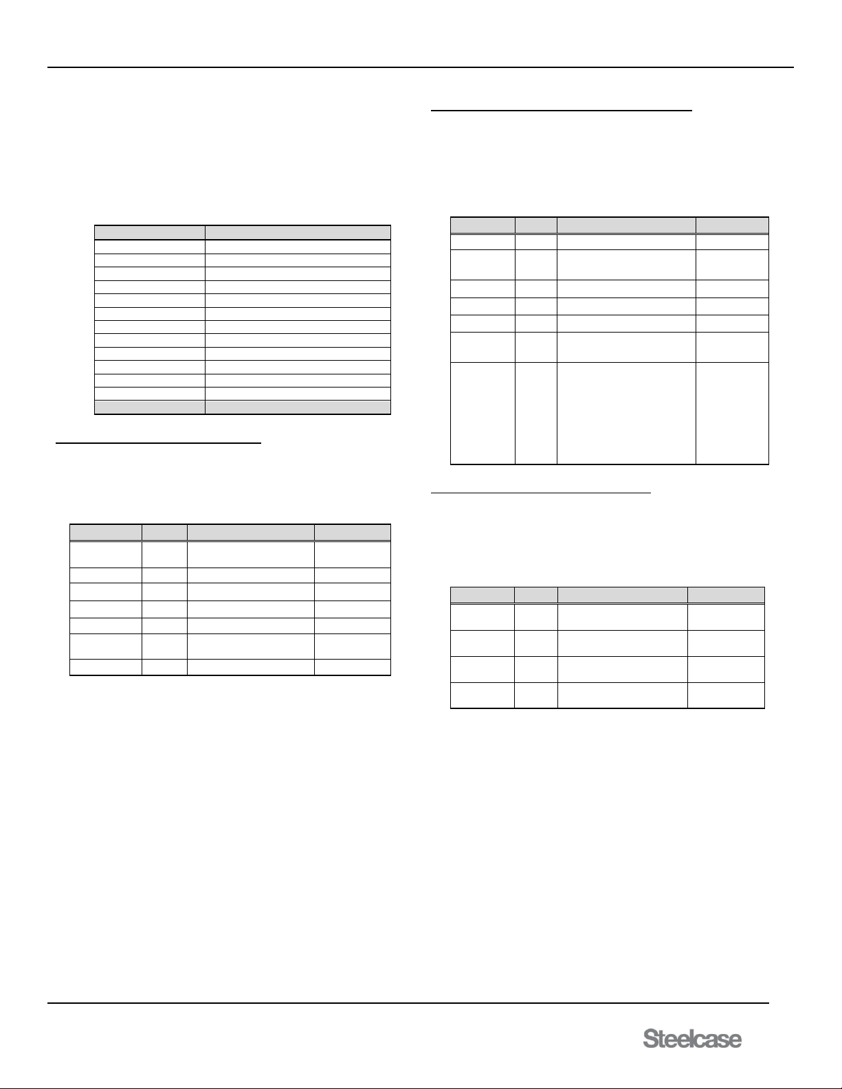
media:scape® Technology Manual
400-0571-012 40
Americas Tech Support: PHONE: 1.800.334.4922 / EMAIL: [email protected]
EMEA Tech Support: PHONE: +33 3 88 13 36 36 / EMAIL: [email protected]
69. [STP]
Return parse able status of the switcher.
Command Format: [STP]
Example:
Send [STP] and the SP106-201/202 returns feedback similar to:
[(12,0,1,1,1,1)(12,0,1,1,1,1)(12,0,1,1,1,1)(12,0,1,1,1,1)(1,4,0,0,1,0,1)(0,0
,0,0)(1,238,52,0,46,19)(1,1,1,1)(1)(0,X,1,1)(0,0,1)(8x4)]
The data is divided into 11 groups containing the entire switcher status.
[
Start feedback
(12,0,1,1,1,0)
Output 1 Properties
(12,0,1,1,1,0)
Output 2 Properties
(12,0,1,1,1,0)
Output 3 Properties
(12,0,1,1,1,0)
Output 4 Properties
(1,4,0,0,1,0)
System Configuration Properties
(0,0,0,0)
Switcher Control Properties
(0,240,49,0,47,39)
System State
(1,1,1,1)
Black Screen Status
(1)
HDCP Engine Status
(0,X,1,1)
Individual Sink Type Status
(0,0,1)
Walk Up Status and DHCP
(8x4)
Matrix Size
]
End feedback
Outputs 1-4 (0,0,0,1,1,1) : 6 properties
Each output group lists from left-to-right the 6 properties in the table
below. The first property is selection of input for that output. The
second property is the cool down period. The next three properties
are the preset AUX inputs 9 through 11. Finally the last property is the
enabling of the walk up experience for each output.
Property
Range
Description
Command
Input
1-12
1-8=PUCK, 9-11=AUX,
12 Walk Up experience
[InOm]
Cool Down
0-60
0=Off, 1=15 sec, etc.
[SOnCDt]
Preset In 9
0,1
To Out 1: 1=yes, 0=no
[PI9On]
Preset In 10
0,1
To Out 1: 1=yes, 0=no
[PI10On]
Preset In 11
0,1
To Out 1: 1=yes, 0=no
[PI11On]
Walk Up
Experience
0,1
0=Disable Walk Up,
1=Enable Walk Up
[SMAxxxx]
System Configuration (1,1,0,0,1,0,1) : 7 properties
The system configuration group lists from left-to-right the 7 properties in
the table below. In the above example, the first two values are set to "1"
meaning the switcher is in collaborative (PUCK control) mode and the
switcher is configured for a single monitor system. The next three values
indicate which outputs are configured for data sharing, in this case "0,0,1"
meaning Output 2 and 3 are not used for data sharing, but Output 4 is the
only data share output.
Property
Range
Description
Command
Mode
1,2
1=Collaborative, 2=Control
[SMCp]
System
Monitors
1-4
1=single, 2=dual,
3=triple, 4=quad
[SMODm]
Data Share
0,1
0=Not, 1=Out 2 = share
[PDO2]
Data Share
0,1
0=Not, 1=Out 3 = share
[PDO3]
Data Share
0,1
0=Not, 1=Out 4 = share
[PDO4]
Priority
0,1
0 = Collaborative,
1 = Priority Mode
[SMPp]
Walk Up
(default 1)
1-6
1 = movie 1 plus still 1
2 = movie 2 plus still 2
3 = movie 3 plus still 3
4 = still 3 only
5 = still 2 only
6 = still 3 only
[WLKn]
Switcher Control (30,12,3,0) : 4 properties
The switcher control group lists from left-to-right the 4 properties in the
table below. In the above example, the standby time is set to 30 or 5
minutes (30 * 10 s intervals). The AUX input standby time is set to 12 or 3
hours (12 * 15 min intervals). The next property is the wake-up on AUX
input. The last value will always be 0 because the power save feature is
not implemented at this time.
Property
Range
Description
Command
PUCK
Standby
0-1080
AUX always on up to
3hrs.
[STBMm]
Standby
Mode
0-48
DISABLED to 12 hrs.
[SSDM]
Wake-Up
On Preset
0-4
0=None, 1=In9, 2=In10,
3=In11, 4=Any
[SWUm]
Power
Save
0
Not Implemented
----
Page 41
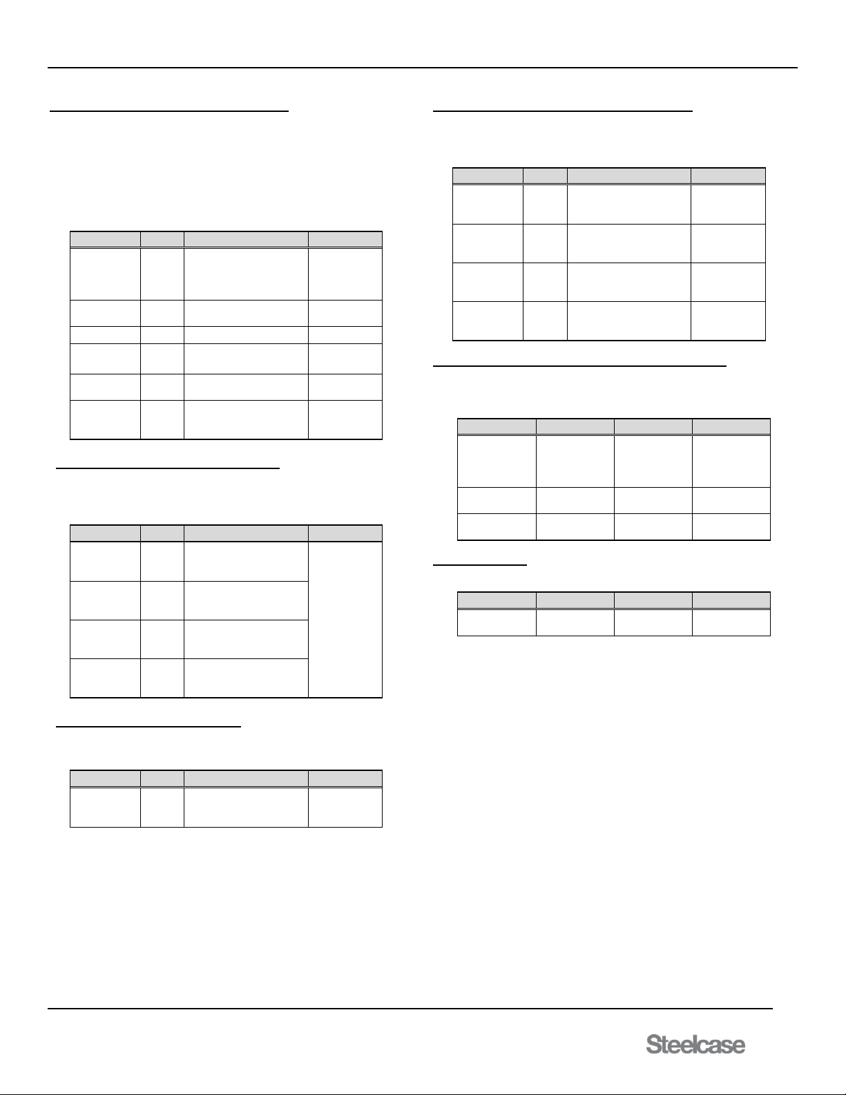
media:scape® Technology Manual
400-0571-012 41
Americas Tech Support: PHONE: 1.800.334.4922 / EMAIL: [email protected]
EMEA Tech Support: PHONE: +33 3 88 13 36 36 / EMAIL: [email protected]
System State (0,240,50,0,47,19) : 6 properties
The system state group lists from left-to-right the 6 properties in the table
below. In the example below, the standby status either in 4 states; awake,
in standby countdown, in shutdown countdown, or standby. Next property
is fan set value which is different than the fan speed percentage; the
percentage is based on the set value. After that is temperature in Celsius.
Then the next property is the current hardware version and software
version of the unit. After that, the Walk Up movie play time in seconds.
Finally, the last property is black screen status for each specific output.
Property
Range
Description
Command
Standby
Status
0-3
0=awake, 1=standby
countdown,
2=shutdown
countdown, 3=standby)
n/a
Fan Set
Value
0-3
0=off, 1=low, 2=high
3=max
x
Temperature
varies
Temperature in Celsius
[TEMP]
Hardware
current
Current hardware
version
[HW]
Software
current
Current software
version
[SW]
Walk Up
movie play
time
0-99
Walk up movie play
time in seconds
[WUPLAYxx]
Black Screen Status (0,0,0,0) : 4 properties
The black screen status lists all four outputs from left being output 1, and
the most right being output 4. The black screen status for each individual
output has two states,
Property
Range
Description
Command
Black Screen
Status
Output 1
0-1
1=enabled, 0=disabled
[SMBxxxx]
Black Screen
Status
Output 2
0-1
1=enabled, 0=disabled
Black Screen
Status
Output 3
0-1
1=enabled, 0=disabled
Black Screen
Status
Output 4
0-1
1=enabled, 0=disabled
HDCP Engine Status (0): 1 property
The HDCP engine within the switcher for all 4 outputs can be disabled or
enabled
Property
Range
Description
Command
HDCP
Engine
Status
0-1
0=enabled, 1=disabled
[HDCPx]
Individual Sink Type Status (0,X,1,0): 4 Properties
Setting the HDCP to auto will enable the outputs to determine the type of
sink types each destination is. HDCP must be set to Auto to detect the
sink if it will allow pass/block HDCP content
Property
Range
Description
Command
Sink type on
Output 1
O,1,X
0 = HDCP blocked
1 = HDCP pass
X = No sink detected
[HDCP?]
Sink type on
Output 2
O,1,X
0 = HDCP blocked
1 = HDCP pass
X = No sink detected
[HDCP?]
Sink type on
Output 3
O,1,X
0 = HDCP blocked
1 = HDCP pass
X = No sink detected
[HDCP?]
Sink type on
Output 4
O,1,X
0 = HDCP blocked
1 = HDCP pass
X = No sink detected
[HDCP?]
Walk Up Type, USB state and DHCP (0,0,1): 3 Properties
The first parameter in the bracket is the walk up type, the second
parameter is the state of the USB stick found within the unit. Lastly the
final parameter is the DHCP is on or off.
Property
Range
Description
Command
Walk Up
type
0-3
0 = USB, 1 =
Video, 2 =
Still, 3 = M:S
OSD
[WLKUPx]
USB State
0-1
0 = (default)
On, 1 = Off
Factory Only
DHCP
0-1
0 = On, 1=
Off
[DHCPx] or
[FXDIPx]
Matrix: 1 Property
This group lists the matrix size of the media:scape.
Property
Range
Description
Command
Matrix Size
8x4 or 12x4
Inputs X
Outputs
[MATS]
Page 42

media:scape® Technology Manual
400-0571-012 42
Americas Tech Support: PHONE: 1.800.334.4922 / EMAIL: [email protected]
EMEA Tech Support: PHONE: +33 3 88 13 36 36 / EMAIL: [email protected]
70. [STP+]
Return viewable switcher status after power reset
Command Format: [STP+]
Example:
Command [STP+] returns viewable switcher information. This command
returns the same information as [STP] but will added comments: (see
below).
[STP+]
[
(12,1,0,0,0,0) OUT1: In,Cd,Pi9,Pi10,Pi11,MP Enable
(12,0,0,0,0,1)
(9,0,1,0,0,1)
(10,0,0,1,0,1)
(1,3,0,0,1,0,1) Ctrl,Monitors,DataShare2-3-4,Priority,WlkUp
(30,0,1,0) StbyTime,StdwnTime,WakeOn,Pwsrv
(0,255,32,48,58,19)Stby,Fan,Temp,Hw,Sw,PlayTime
(0,0,0,0) Black screen enable Out 1~4
(0)(1,1,1,1) HDCP engine disabled, sink type 1~4
(0,X,0) WalkUpType, USB (0=default),DHCP
(8x4) Matrix Size
]
Grps 1-4 In= Input connected to output ........... [IxOy]
Cd= Cool down time ......................... [SOxCDy]
Pi9= Preset Input 9 on/off ................. [PI9On]
Pi10= Preset Input 10 on/off .............. [PI10On]
Pi11= Preset Input 11 on/off .............. [PI11On]
Media Player enabled/disabled ......... [SMAxxxx]
Grp 5 Ctrl = control mode on or off ............. [SMCn]
Monitors = system mode ................... [SMODn]
Data Share on outputs 2,3,4 ............. [PDOn]
Priority mode on or off ....................... [SMPn]
Walk up experience that is set .......... [WLKn]
Grp 6 Standby Time ................................... [STBM]
Shutdown time .................................. [SSDM]
Wake on AUX connection .................. [SWU]
Power save ....................................... N/A
Grp 7 The standby mode of switcher .......... Factory
Fan set value .................................... N/A
Temperature ..................................... [TEMP]
Hardware version .............................. [HW]
Software version ............................... [SW]
Play time of walk up movie ............... [WUPLAY]
Grp 8 Black screen enable Out 1~4 ............ [SMBxxxx]
Grp 9 HDCP engine state (1=disabled) ....... [HDCP]
Grp 10 Walk up experience type ................... [WLKUPn]
USB path (0= MPGs,1=IDLE) ........... Factory
DHCP on or off (0=use fixed IP) ........ [DHCPn] or [FXDIPn]
Grp 11 Matrix size ........................................ [MATS]
71. [STS]
Displays statistic counters
Command Format: [STS]
Example: Command [STS] returns statistical data that indicates the unit
has gone through 26 power cycles, 11 sleep cycles, 6 Hours of active
time, and PUCK1- 8 connection counters. PUCK 1 has 9 counts of
connecting with a source.
((PWR:000026)(SLP:000011)(HRS:000006)(PK1:000009)……(PK8:000
005))
72. [STV]
Data share settings from left to right Outputs 1-4.
Command Format: [STV]
0=output is not shared
1=output is shared
X=output is not available for sharing in this monitor configuration
Example:
Command [STV] returns feedback [x,x,0,1] which has Out1 and Out2 not
configured for data share configuration. Out3 is not shared, and Out4 is
shared.
73. [STVC]
Display a matrix of the preset inputs and data share settings.
Command Format: [STVC]
Example:
OUT: 1 2 3 4
09: - - X - Preset Input 9 on Output 3 [PI9O3]
10: - - - X Preset Input 10 on Output 4 [PI10O4]
11: - - - - Preset Input 11 not used. [PI11O0]
DS: - - - X Data share on Output 4 [PDO4]
74. [SW]
Command displays the uploaded software version for that unit.
Command Format: [SW]
Example:
Command [SW] will return [22] Software Version 22
75. [SWUx]
Set the wake up on preset input number and send acknowledgement
"[x]" (the value you set) feedback. If the system is in standby, applying
an AUX signal to this input will "wake up" the system. A PUCK input is
not required.
Command Format: [SWUx]
x = Preset wake up (m = # from 0 to 4)
0 = No Wake Up
1 = Wake Up On Input 9
2 = Wake Up On Input 10
3 = Wake Up On Input 11
4= Wake Up on Any AUX Input
Example:
Set the switcher to wake up when an AUX signal is applied to Input 9
regardless of whether or not PUCKs have inputs.
[SWU1]. feedback [1]
76. [TEMP]
Returns the media:scape internal temperature in Celsius format.
Command Format: [TEMP]
Example:
Read the temperature for the switcher by sending the following:
[TEMP] and the media:scape will return the following: [32C]
Page 43

media:scape® Technology Manual
400-0571-012 43
Americas Tech Support: PHONE: 1.800.334.4922 / EMAIL: [email protected]
EMEA Tech Support: PHONE: +33 3 88 13 36 36 / EMAIL: [email protected]
77. [UFAx]
The [UFA] command enables unsolicited feedback. This command
provides feedback to all events. In addition, it provides feedback on
power up, power down (sleep mode) and power button pressed.
Activate/deactivate unsolicited feedback and send acknowledgement
"[ ]." Unsolicited feedback reports switching and signal detect events.
Command Format: [UFAx]
Switching events are reported in the format [xxy].
[xxy] xx = 2-digit Input (01-08 PUCKs, 09-10 HDMI,
11 Walk up experience)
y = 1-digit Output (y = # from 1 to 4)
Signal detect events are reported in the format [Ixxy].
[Ixxy] xx = 2-digit Input (01-08 PUCKs, 09-10 HDMI)
y = Detection (0=signal lost, 1=signal detected)
x = UFA mode (m = 0 or 1)
0 = unsolicited feedback OFF
1 = unsolicited feedback ON
Example - Activate Feedback:
Activate unsolicited feedback by sending the following command:
[UFA1] Unsolicited feedback activated
Example - Connect PUCK to Video Signal
The following unsolicited feedback is reported when PUCK 3 is
connected to a laptop supplying a HDMI signal:
[I031] New signal detected on Input 3
Example - Select Output 1 on PUCK
The following unsolicited feedback is reported when the Output 4 icon on
PUCK 3 is selected:
[034] Input 03 to Output 4
[S1] system went to sleep
[S0] system woke up
[P1] power button was pressed
[F0] fan is off
[F1] fan half speed
[F2] fan full speed
[H1] heat alarm activated
[H0] heat alarm is back to normal
78. [UFS]
Displays [UFA] status.
Command Format: [UFS]
Example:
Using command [UFS] while [UFA] is ON will return [1].
79. [USLEEP]
Sets the unit to shutdown/sleep until woken up; if no PUCK signals.
UDP Format: [USLEEP] (port 30303)
Example:
Command will shut down unit until unit is woken up. If unsolicited
feedback is turned ON, it will return [S1].
80. [UWKUP]
This command will wake the unit up.
UDP Format: [UWKUP] (port 30303)
Example:
Command will wake up the unit. If unsolicited feedback is turned ON, it
will return [S0].
81. [VER]
This command displays the current version for that particular unit.
Command Format: [VER]
Example:
Command will return [SP106-20x 1.0.20].
82. [WKUP]
Wakes up the system, same as [WKP] command.
Command Format: [WKUP]
Force the switcher to wake up by sending the following command:
[WKUP]
*If unsolicited feedback is turned on, will return with:
[S0] System woke up.
83. [WKP]
Force the system to wake up without having to apply a video signal. The
system wake up and goes through it normal initialization procedure.
Keep in mind that if no inputs are applied to PUCKs the system will go to
sleep (shutdown) once the STANDBY and SHUTDOWN timers have
timed out. System wake up is about 12-15 seconds.
Command Format: [WKP]
Example:
Force the switcher to wake up by sending the following command:
[WKP]
*If unsolicited feedback is turned on, will return with:
[S0] System woke up .
84. [WLKx]
Select the default "walk up" experience for media:scape. Walk up
experience 1 is the default.
Command Format: [WLKx]
x = Option number (x = # from 1-8)
1 = still #4 plus movie #2 (default)
2 = still #5 plus movie #1
3 = still #6 plus movie #3
4 = still #4 only - no movie
5 = still #5 only - no movie
6 = still #6 only - no movie
7 = still #9 plus movie #8
8 = still #9 only - no movie
Example:
Set the switcher to display the default "walk up" experience by sending
the following command:
[WLK1]
Page 44
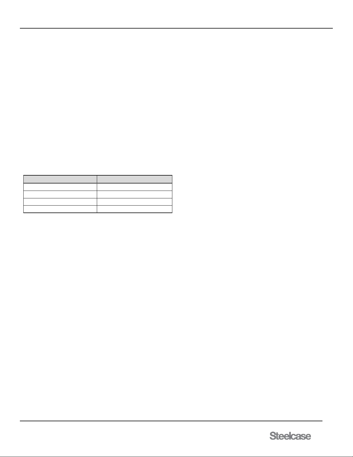
media:scape® Technology Manual
400-0571-012 44
Americas Tech Support: PHONE: 1.800.334.4922 / EMAIL: [email protected]
EMEA Tech Support: PHONE: +33 3 88 13 36 36 / EMAIL: [email protected]
85. [WLKPEn]
Plays selected walk up experience regardless of memory setting.
Command Format: [WLKPEn]
n = Walk up Experience (1-8)
Example:
Inputting command [WLKPE5] will play walk up experience # 5.
86. [WLKPTn]
Play walk up track and loops until overwritten.
Command Format: [WLKPTn]
n = Track No. (1-8)
Example:
Command [WLKPT1] will play the default track looped until command is
overwritten.
87. [WLKUPx]
Set up Walk Up Experience type.
Command Format: [WLKUPx]
x = type (0-3)
Type
Walk Up Experience
0 = USB
Play USB movie + USB still
1 = Video
Play USB movie + MP image
2 = Still
MP image Only
3 = m:s
OSD “MEDIA:SCAPE”
Example: Set up the Walk UP experience to the OSD message
“MEDIA:SCAPE” by using command [WLKUP3]. Walk Up Experience
will be set to OSD message when Walk Up Experience is enabled.
88. [WUPLAYxx]
Set the Walk up movie play time. After this play time expires, the still
image is displayed.
Command Format: [WUPLAYxx]
xx = Play time in seconds (xx = 1-99)
Example:
Movie track will play 1 minute every time the WUX is played if command
[WUPLAY60] is applied
89. ?Steelcase (UDP port 30303)
This is a UDP command to find switchers. Each switcher responds to
the broadcast with its IP information and MAC address.
Example:
Send ?Steelcase to UDP port 30303 and receive feedback similar to
the following:
[SCS116000000,00:04:A3:10:18:E1,00023,192.168.10.81,
255.255.0.0,192.168.1.1, TCP=0,DHCP,IP=AUTO ]
SCS116000000 has switcher information or can be a programmed alias
name (see [CSN] command).
In the SCS example, the first 2 digits “11” are hardware revision,
followed by 2-digit software “60” revision.
The remaining 0s are not implemented.
Next is the network configuration, MAC address, TCP/IP port (always
23), the programmed IP address, the subnet mask, and the gateway.
The next field displays the number of TCP sockets currently open.
The next field is the programmed IP configuration in use, either DHCP
or FIXED.
The last field is how the IP in use was derived and can be either AUTO
or MEM. Note that the mode can be DHCP, but without a server the IP
use the programmed static IP address.
Page 45

media:scape® Technology Manual
400-0571-012 45
Americas Tech Support: PHONE: 1.800.334.4922 / EMAIL: [email protected]
EMEA Tech Support: PHONE: +33 3 88 13 36 36 / EMAIL: [email protected]
Table List Summary of Commands:
1. [ACTIVE] Displays bootloader or application mode
2. [AUTH] Manually check HDCP compliance
3. [BLV] Display bootloader version
4. [BLS] Display bootloader status
5. [BLS+] Same as [BLS] with text
6. [CECx] Verify if display is CEC compatible
7. [CRC] Read switcher TCP/IP configuration
8. [CRC+] Read switcher TCP/IP configuration after reset
9. [CSB] Set subnet of switcher
10. [CSB+] Set subnet of switcher after reset
11. [CSG] Set gateway of the switcher
12. [CSG+] Set gateway of the switcher after reset
13. [CSN] Set switch alias name for ?Steelcase
14. [CSP] Set static IP address of switcher
15. [CSP+] Set static IP address of switcher after reset
16. [DHCPx] Set up either DHCP or fixed IP address
17. [DRV] Displays BIOS versions
18. [FAN] Set to return fan status feedback
19. [FANx] Set fan speed for troubleshooting
20. [FXDIPx] Toggle between fixed IP and DHCP
21. [HDCP] Display content protection engine state
22. [HDCPx] Set HDCP engine ON/OFF or AUTO
23. [HDCPIx] Display content protection of input
24. [HDCPM] Display saved status in memory
25. [HDCP?] Display content protection support for outputs
26. [HW] Displays hardware version
27. [INEQ] Display input equalization (eq) setting
28. [INEQB] Display input eq. for each input
29. [INEQx] Set input equalization
30. [IPL] Display network IP lease time
31. [IPL+] Display lease, renew, and remaining times
32. [IPR] Force lease renewal
33. [IxOy] Connect any input to any output
34. [IPOn] Deselect AUX like PUCK
35. [ImBn] Select AUX like PUCKS
36. [MAT] Display model number
37. [MATS] Display matrix size
38. [OSD] Display settings
39. [OSDFnmyyyy] Display session on-screen
40. [OSDNnmdcccc] Numeric text box
41. [OSDPOSn,x,y] Upper right OSD location
42. [OSDSZn,w,h] Height & width of OSD box
43. [OSDTxx] OSD box timeout when delay is enabled
44. [OSDXn] Clear numeric text box properties
45. [PDOx] Set data share output for video conferencing
46. [PIxOy] Set AUX inputs to override walk up experience.
47. [PKRSTn] Reset PUCK connection counters
48. [PLM] Play current Walk Up experience
49. [SCPx] Enable/Disable scale power
50. [SFT] Soft Reset unit as though it is powered up
51. [SIB] Return parse able general system information
52. [SIS] Same as [STS]
53. [SIT] Return parse able system information
54. [SIT+] Same as [SIT] but PUCKS type is queried
55. [SLEEP] Shut-down media:scape system
56. [SMAxxxx] Enable wake up display only for specific output
57. [SMBxxxx] Enable black screen for specific output
58. [SMCx] Set control mode of switcher
59. [SMODx] Set number of displays connected to switcher
60. [SMPx] Set control mode of switcher
61. [SN] Return the 13 digits serial number
62. [SOxCDy] Set cool down time for projector control
63. [SSDMx] Set switcher shut-down delay time
64. [STBMx] Set switcher standby delay time no PUCKs
65. [STDWN] Force the switcher to standby mode
66. [STI] Input status command
67. [STM] Feedback on Media Player Configuration
68. [STO] Output status command
69. [STP] Return parse able switcher status.
70. [STP+] Return parse able switcher status after reset
71. [STS] Displays Statistic Counters
72. [STV] Data share settings
73. [STVC] Display matrix of presets
74. [SW] Display software version within the unit
75. [SWUx] Enable/disable system wake-up mode
76. [TEMP] Read switcher temperature
77. [UFAx] Enable/disable unsolicited feedback.
78. [UFSx] Displays [UFA] status
79. [USLEEP] Set the unit to shutdown/sleep until woken up
80. [UWKUP] Set to wake the unit up
81. [VER] Displays version for that particular unit
82. [WKP] Wake-up media:scape system
83. [WKUP] Wakes up the system, same as [WKP]
command
84. [WLKx] Set walk-up experience used on power-up
85. [WLKPEn] Play Walk Up experience
86. [WLKPTn] Play Walk Up track
87. [WLKUPx] Set Walk Up experience type
88. [WUPLAYxx] Walk Up movie play time
89. ?Steelcase UDP command to find switcher IP
Page 46
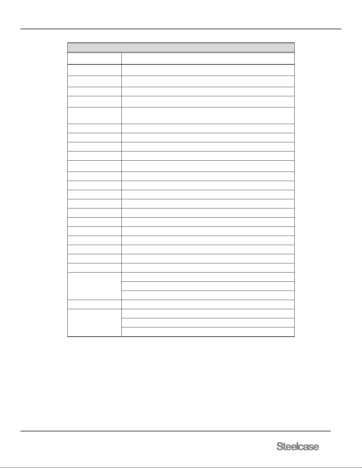
media:scape® Technology Manual
400-0571-012 46
Americas Tech Support: PHONE: 1.800.334.4922 / EMAIL: [email protected]
EMEA Tech Support: PHONE: +33 3 88 13 36 36 / EMAIL: [email protected]
Firmware Change Log
Firmware Version
General Description of Change.
2.0.8
New TCP bootloader using port 5023. Clean up [CRC] commands. Add
register changes to fix flashing on inputs. Modify fan speed functionality.
1.1.22
Add support for flex and permanent serial number. Modify OSD page 3,
combine bios to one block, add serial no and mac address
1.1.21
Replace web busy image.
1.1.20
Modify user movie interrupt to set presets and data share. Add new commands
for configuration app: [SIS] [SIB] [SIT]
1.1.19
Fix audio stream, check SPDIF vs. HDMI at each switch. Add missing
unsolicited feedback for puck press and data share. New command [STA] - Out
Audio (0=none,1=SPDIF,2=HDMI)
1.1.18
If awake and [WKP] then [ACTIVE] Remove UDP unsolicited feedback
1.1.17
Fix multi-socket UNSOL_FDB to all sockets
1.1.16
Turn off scaler power at sleep. Add command [SCPn] scaler power on-off
1.1.15
MULTI-SOCKETS - first release
1.1.14
Add AUX select like PUCK command: [ I x B y ].Pucks ignore any switch
number greater than the system mode
1.1.13
Change switch command to [IPOx]; AUX de-select like PUCK.
1.1.12
Add new switch command [IxOP]; AUX de-select.
1.1.11
Add OSD items and counters for page 5 and diagnostics page 6
1.1.3
FAN reporting adjustment
1.1.2
OSD changes to list DCP as HDCP, by default HDCP is set to AUTO
1.1.1
[CSB+][CSG+][CSP+][CRC+] added commands and OSD fix
1.1.0
HDCP auto detection
1.0.20
Cleanup to OSD
1.0.19
2nd Method for factory reset added, OSD function added
1.0.10
[SMB] defaults to O. Allow full control of [SMB] in OSD
1.0.9
Add USB Commands for MPEG upload. Not implemented
1.0.8
Update TCP/IP stack. Return to AUX after movie, if set as
Preset input. Add [SMB] command for disabling video
Conference outputs. Adjust fan start-stop voltage.
1.0.7
Add independent OSD control for video conferencing
1.0.6
Add status information to [STP] command
Add CEC test command
Add video conference support to multiple monitors
Page 47
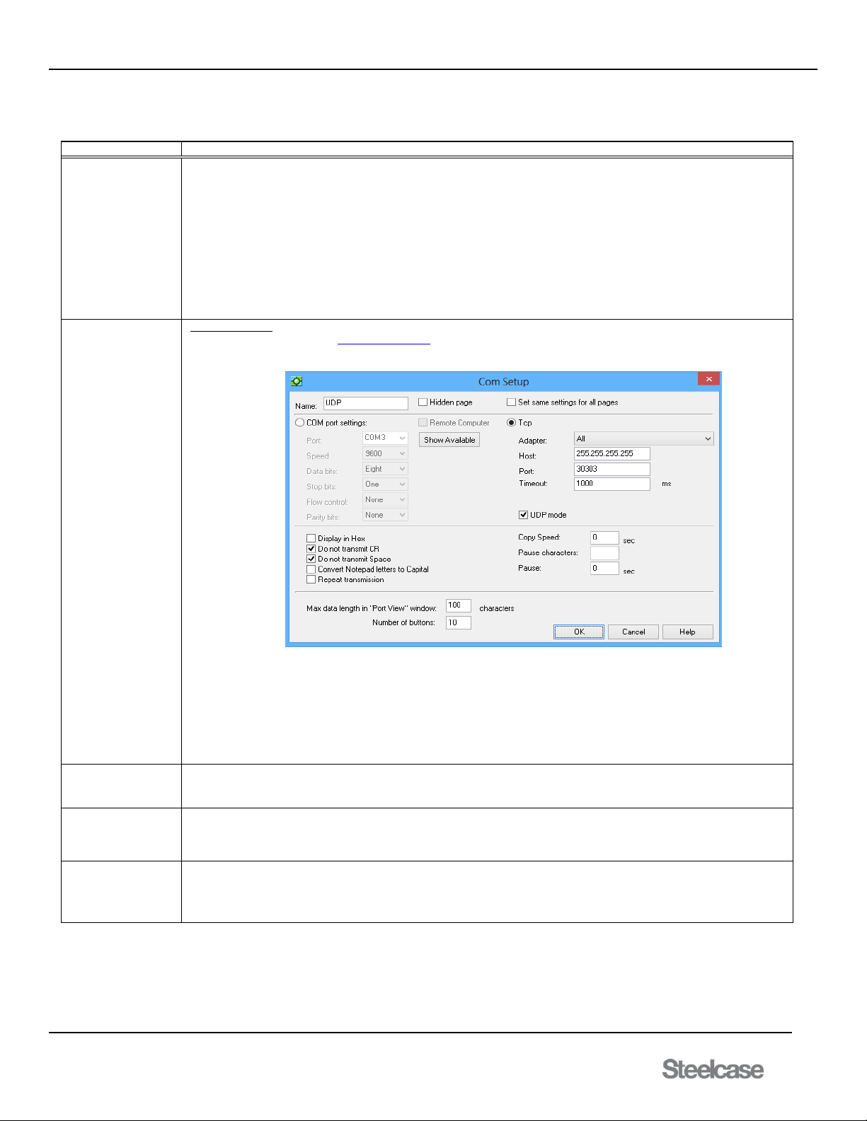
media:scape® Technology Manual
400-0571-012 47
Americas Tech Support: PHONE: 1.800.334.4922 / EMAIL: [email protected]
EMEA Tech Support: PHONE: +33 3 88 13 36 36 / EMAIL: [email protected]
8. Troubleshooting Guide
We have carefully tested and have found no problems in the supplied media:scape. However, we would like to offer suggestions for the following.
Symptom
Resolution
Cannot Make TCP
Connection.
1. Check the LEDs on the Ethernet connector. A green LED indicates the media:scape is recognizing the network and a
flashing amber LED indicates communication traffic over the network.
2. Make sure the control application has the correct TCP/IP address for the media:scape.
3. Review the TCP control section of this manual. Check the Ethernet properties for the media:scape. Each media:scape
is shipped with the following static IP settings: IP=192.168.10.81, Subnet Mask=255.255.255.0,
Gateway=192.168.10.1, and Port=23 but must be configured for use on other networks; reference commands [CSN],
[CSP], [CSB], [CSG], and [CRC].
4. Check with your IT administrator to verify the media:scape was assigned a valid static IP address that is accessible
over the LAN and does not conflict with other devices on the network. Each Switcher controller requires its own
unique static IP address. The DOS "ping" command can be used to determine if the internal server is up and to verify
the assigned IP address is "reachable" on the IP network.
Don't Know
or Forgot
IP Address.
UDP Broadcast
1. Download AVSNAP from http://avsnap.com/ and go into communication mode.
2. Send a UDP broadcast to 255.255.255.255 port 30303.
Figure 1: AVSNAP Com Setup
Using the following data string: ?Steelcase
*UDP commands must be sent from the notepad within AVSNAP to the terminal.
3. The media:scape responds with the following data in a UDP packet to the host IP:
[SCS002200000 ,00:04:A3:10:1D:28,00023,192.168.1.228,255.255.255.0,192.168.1.254]
The data string contains the hardware/software version, MAC address, TCP port number, IP address, subnet mask,
and gateway.
Can establish UDP
communication but not
TCP communication.
Once UDP communication is established and IP address is given, configure IP address in Local Area connection. Refer
to section 7.4.
White screen is
displayed instead of
the Walkup
Experience.
Reset power to the switcher. If problem persists, then internal USB memory failed, replace switcher by contacting
Steelcase.
The Media Player
menu is displayed
after firmware
upgrade.
Reset power to the switcher. If problem persists, media player requires firmware update. Replace switcher by contacting
Steelcase.
Page 48
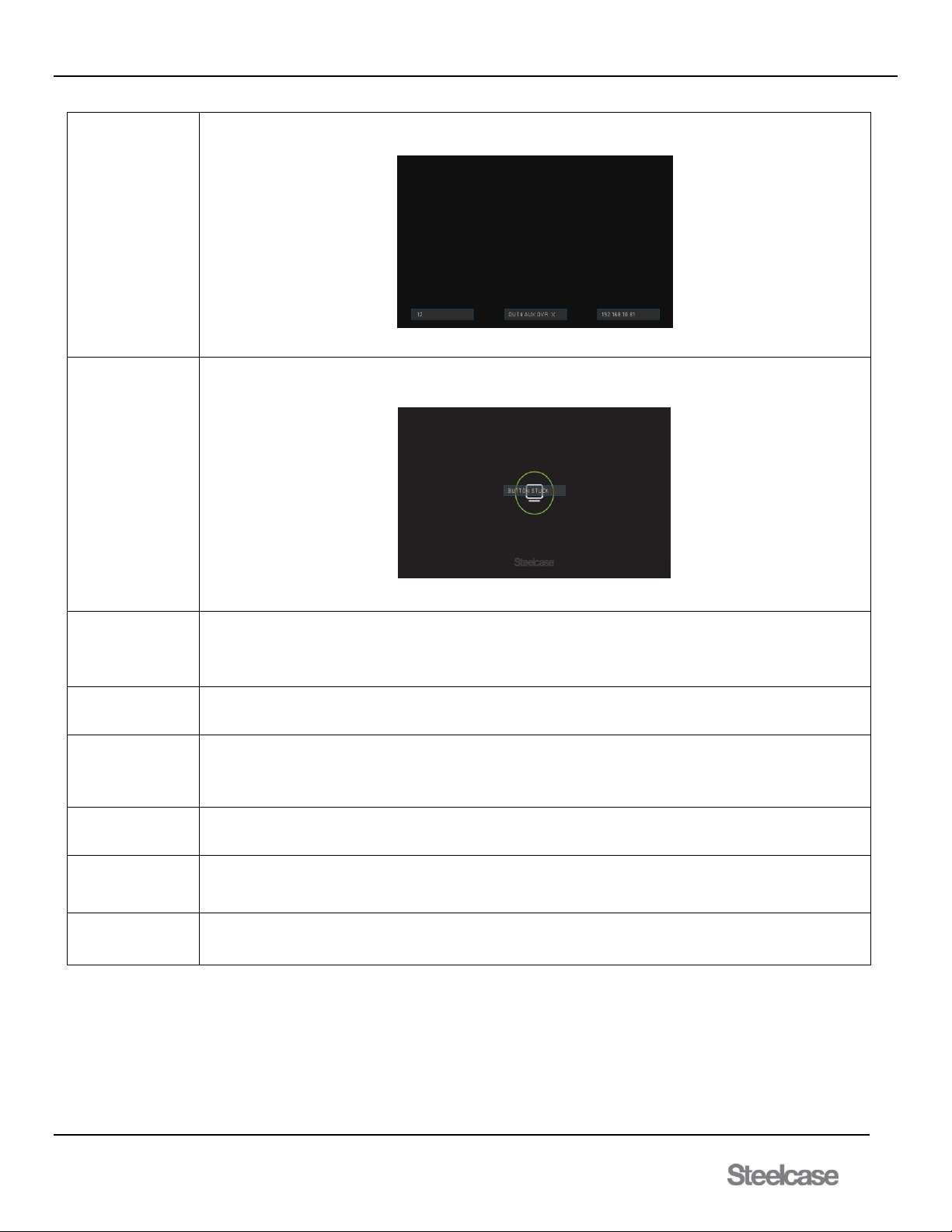
media:scape® Technology Manual
400-0571-012 48
Americas Tech Support: PHONE: 1.800.334.4922 / EMAIL: [email protected]
EMEA Tech Support: PHONE: +33 3 88 13 36 36 / EMAIL: [email protected]
Walk-up experience
displays only once
during power up and
then stops.
Switcher is miss-configured. Adjust AUX OVR setting on the OSD for each output using configurable field’s #9-#12. Set
override to None (X) in each setting.
Figure 2: Output 4 set to none
Switcher goes into
power-up OSD mode
after power is applied.
Bezel switch is shorted. Replace bezel switch with SP106-105. Contact Steelcase for all replacement components.
Make sure nothing is pressing down bezel button
Figure 3: Bezel Button pressed down too long
Pressing and holding
bezel button does not
display OSD menu,
PUCK does not light
up.
Check that one of the PUCKs is connected to PUCK port #1. Only a PUCK connected into port #1 will light up during
OSD configuration.
Unable to get into the
firmware upgrade
mode.
The only way to get into upgrade mode is using the upgrade application.
Switcher works 5-10
minutes after power
up and then stops
responding.
Look at the side of the switcher through the open vents and verify that three internal LEDs are flashing fast and one
flashing slow. If the LEDs are not flashing, microprocessor is not responding. Upgrade BIOS and switcher firmware to the
latest version. If behavior continues, replace switcher.
PUCK flashes all icons
white and green.
Reset power to the switcher. If flashing continues, then move PUCK to a different port and reset the power the switcher.
If flashing still continues replace the PUCK by contacting Steelcase.
Fan only goes to high
speed. The fan is
unable to start in low
speed.
Upgrade switcher to the latest firmware.
No display on output 1
If display on output 1 is not detected, the other outputs will display the following message “CONNECT OUT 1”. If you see
this message, make sure that at least one display is connected to output 1 of the switcher.
Page 49
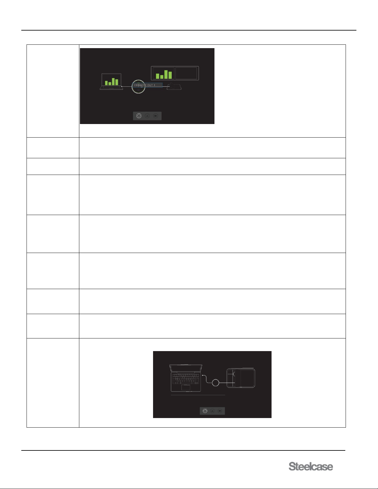
media:scape® Technology Manual
400-0571-012 49
Americas Tech Support: PHONE: 1.800.334.4922 / EMAIL: [email protected]
EMEA Tech Support: PHONE: +33 3 88 13 36 36 / EMAIL: [email protected]
Figure 4: Connect Output 1
Unable to reset
switcher to factory
condition.
Upgrade switcher to the latest firmware. Follow user guide exactly (Download the latest version). On the bottom left
corner of each page, there is a 10 digit number, the last three digits is the version of the user guide.
AUX audio is not
routed to HDMI output.
AUX audio is only routed to 3.5mm audio jack located next to the 4 HDMI output connectors.
When monitor is
connected to the
system after it is
powered, monitor
displays “Not
Supported Resolution”
message.
Authentication of monitors is done during power up only. Connect the monitor to the switcher and then power up the
system.
Protected content is
not displayed on the
Data Share output
when connected to
video conference
equipment.
Protected output is not allowed to go to VC output based on the HDCP specification. Output from switcher automatically
detects non HDCP display and switches to non HDCP mode. Use OSD to force switcher to HDCP or non HDCP mode.
System powers up,
then shuts down and
powers up again. The
cycle continues every
5-10 seconds.
Unplug all PUCKs except PUCK 1. Unplug all scalers and connect display directly to the output 1. Power up the system
and check if it still cycles. If it still cycles, then try a different power supply. If it stops cycling, then add one PUCK at a
time until the cycle repeats without unplugging the power to the unit. If the system operates properly, but when it is
powered it starts cycling again, then replace the power supply.
Monitor only displays
720p resolution.
Check setting on the scaler and adjust to 1080p by pressing resolution/mode button on the scaler to show the on-screen
menu. Pressing the mode/resolution button again will move the highlighted field to the next field. Leaving highlighted field
selected will switch to the selected resolution within 5 seconds.
Monitor displays OSD
when switching
between different
PUCK inputs.
Reset scaler to default so that output is not interrupted. Press and hold down resolution/mode button for 5 seconds to set
scaler to default settings.
Walk Up Experience is
pixilated
Contact Steelcase for multiple available solutions.
Figure 5: Pixilated image
Page 50
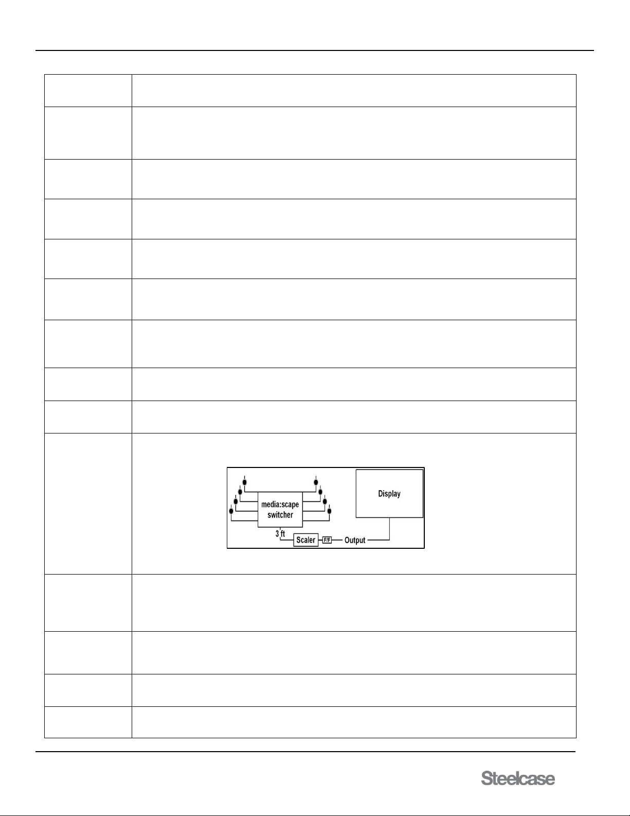
media:scape® Technology Manual
400-0571-012 50
Americas Tech Support: PHONE: 1.800.334.4922 / EMAIL: [email protected]
EMEA Tech Support: PHONE: +33 3 88 13 36 36 / EMAIL: [email protected]
The firmware upgrade
program does not find
switcher.
Make sure computer is on the same network and has the same IP range as a switcher.
Number of outputs
selected is not stored.
When switcher is
reset, unit returns to 4
outputs.
Update switcher to the latest firmware.
Output intermittently
flashes between video
and blank screen.
Make sure the switcher is running the latest firmware; minimum v2.0.8.
Move PUCK to a different input if available.
If flashing continues, then replace switcher.
When computers are
connected and power
is reset, switcher does
not power up.
Unplug all sources (computers) before resetting power to the switcher.
MAC computer takes
10 seconds before it is
able to display an
image on m:s.
MAC computers have HDCP authentication that sometimes take longer than a PC. Update MAC to the latest software
version and operating system.
Switching between
MAC and PC
produces magenta
hue video.
Verify that monitors are capable of both RGB and YPbPr color space. This occurs when a computer monitor and
television are installed on the same m:s system. Computer monitors do not have YPbPr color space. Change monitors
so that they have the same color space capability.
No video image on
one or more monitors,
PUCKs work fine.
Remove scaler and connect the output from switcher directly to the display. If the image appears, then replace scaler
Verify that there is no ground loop between media scape and the display. Ground loop occurs when the display is
connected to a different AC phase than m:s. The only way to fix it is to call the electrician and verify that both m: s and
display is connected to the same phase and are grounded to the same location on the electrical panel.
The image disappears
when dongle cable is
moved.
Replace dongle cable by opening up PUCK. Instructions can be found within the manual.
The image disappears
when PUCK cable to
the M: S is moved.
Replace PUCK to switcher cable by opening up PUCK. Instructions can be found within the manual.
I bought an HDMI
cable to extend the
distance to the display
and now there is no
image.
Move scaler next to switcher using 3 ft. HDMI cable AWG22. Take output from the scaler add gender changer in
between, and then connect the cable to the monitor.
We used our own
HDMI cables; image is
OK without scaler, but
no image with a
scaler. Cables are
25 ft.
Use only cables from Steelcase. They were designed to provide a proper wire gauge and shielding for scaler operation.
We were trying to
extend PUCKs, we
could not make them
work.
Make sure to use PUCK extension cable before extending PUCK using HDMI cable. Make sure to use only AWG22
HDMI cable. Use only Steelcase supplied PUCK extension cables.
Loosing TCP/IP
connection
intermittently.
Update switcher to the latest firmware.
Unable to connect two
clients to the switcher
TCP socket.
Verify the bootloader is not running.
Make sure you have the correct IP and select port 23.
Figure 6: Simple Block Diagram of Solution
Page 51
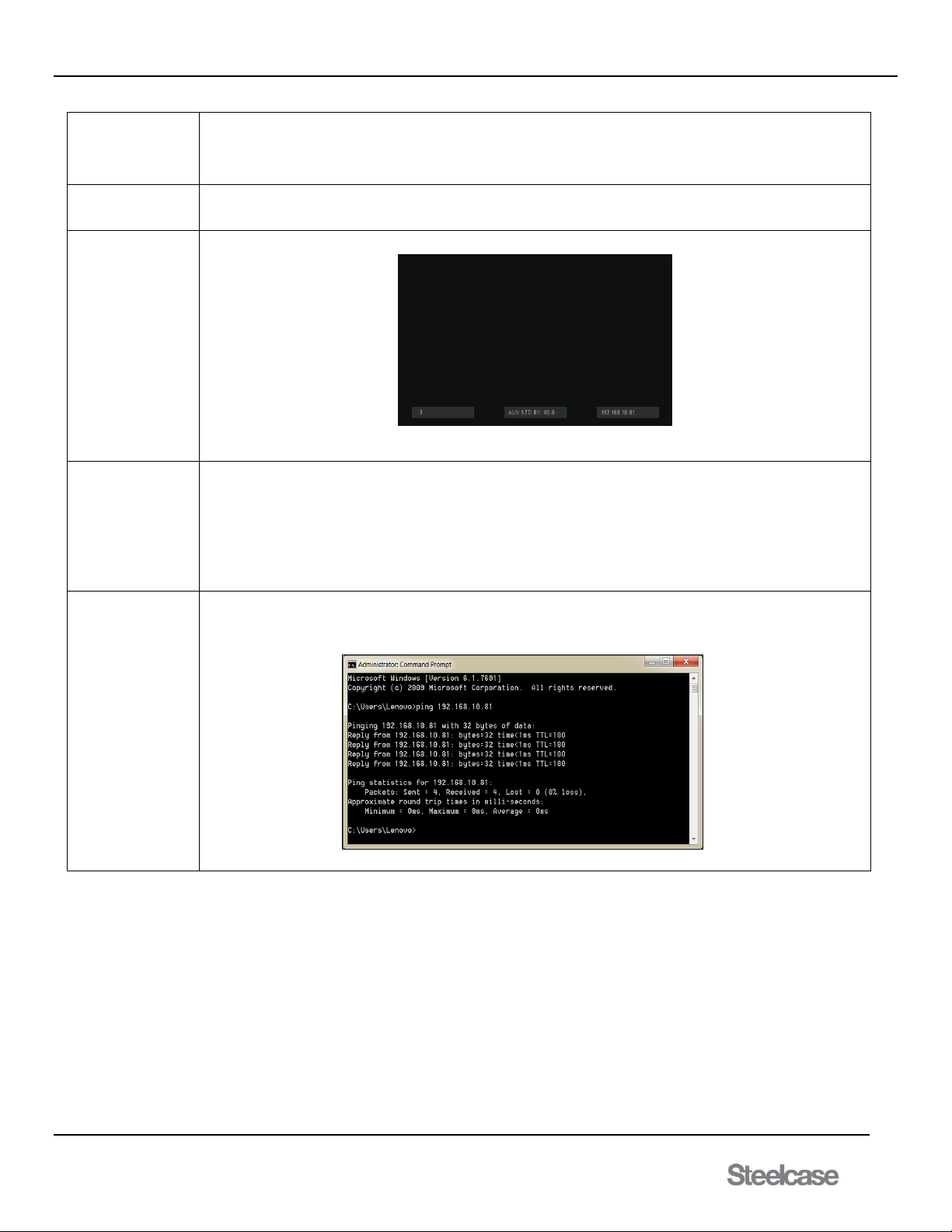
media:scape® Technology Manual
400-0571-012 51
Americas Tech Support: PHONE: 1.800.334.4922 / EMAIL: [email protected]
EMEA Tech Support: PHONE: +33 3 88 13 36 36 / EMAIL: [email protected]
I am trying to switch to
the output that does
not have a monitor
connected and I get
an error.
The m:s does not allow switching to outputs that do not have a display connected.
OSD temperature is
not displaying
correctly.
Update switcher to the latest firmware version.
M:S turns off when left
unattended. We use
AUX1 to display digital
signage.
Adjust AUX input timeout on m:s OSD using configurable field #3.
Figure 7: Configurable Field 3 set to always on
When PUCK is
connected to a source
(PC or MAC), PUCK
momentarily turns
icons ON and then
they turn OFF.
Unable to select
source and display it
on the monitor
The m:s sees the plug-in event but is not able to see the video signal. Connect PC directly to TV and see if the image is
displayed. If it is displayed, then verify that PC can read EDID. Plug computer into PUCK and then go to control panel,
display monitor properties and check if Steelcase m:s is showing as vendor. If Steelcase is not shown as a display, then
dongle cable or PUCK to switcher cable is damaged.
Using Command
Prompt to ping
media:scape
Type in the IP address of the media:scape after the ping command in the command prompt. For example: 192.168.10.81
Verifies communication on the network level between the media:scape and the PC used for configuration.
Figure 8: Command Prompt Ping
Page 52
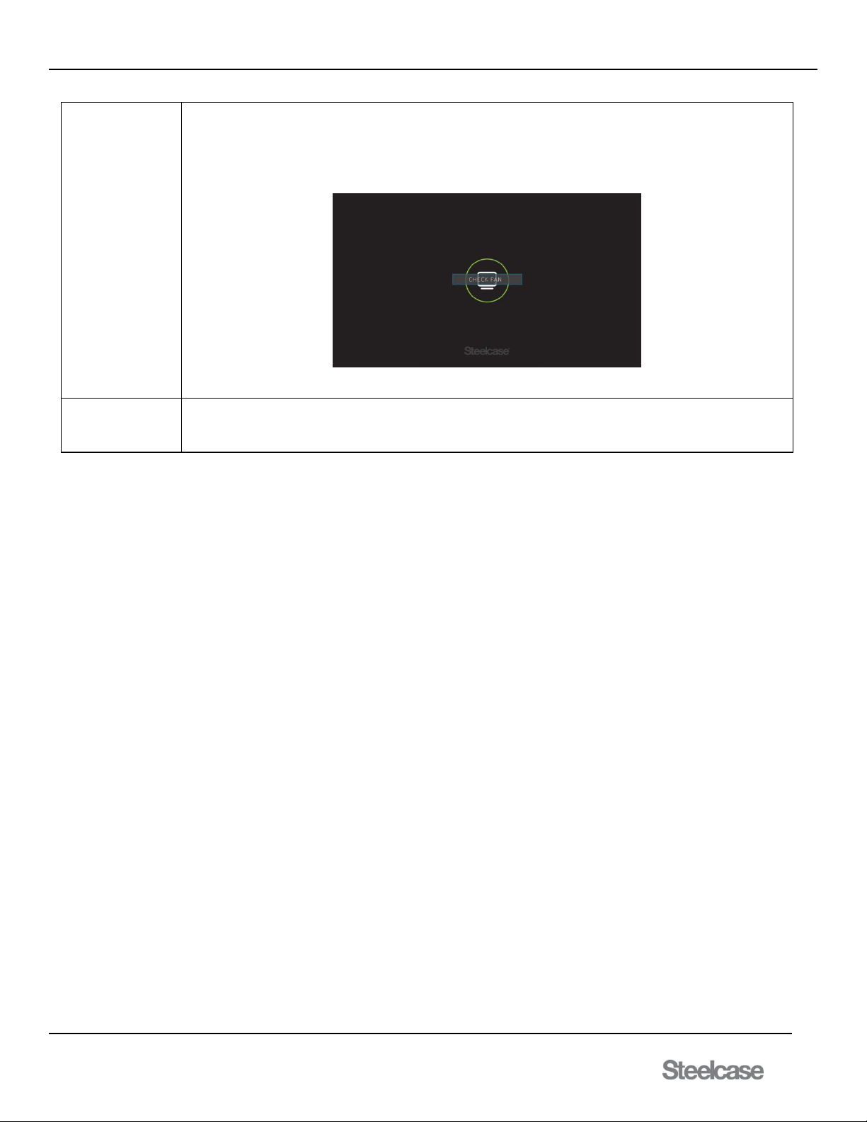
media:scape® Technology Manual
400-0571-012 52
Americas Tech Support: PHONE: 1.800.334.4922 / EMAIL: [email protected]
EMEA Tech Support: PHONE: +33 3 88 13 36 36 / EMAIL: [email protected]
The media:scape
switcher is
overheating
Unplug power for a few seconds then plug it in and see if the fan will go to high speed for a few seconds. If it does, then
everything is OK with the switcher. Inspect location of the switcher to make sure wires or other item does not impede fan
rotation. Inspect location of the switcher to make sure there is access to fresh air. Metal shroud does not count as
insulator. Wood panels count as insulator. Open up panels to create venting holes to allow cool air into the switcher
location. Make sure to upgrade switcher to the latest version.
Figure 9: Check Fan Status
Contact Steelcase
Technical Support
Type in the IP address of the media:scape into your web browser.
 Loading...