

Steelcase Convene Assembly Manual
Steelcase, Inc.
Grand Rapids, MI 49501
U.S.A.
1-888-783-3522
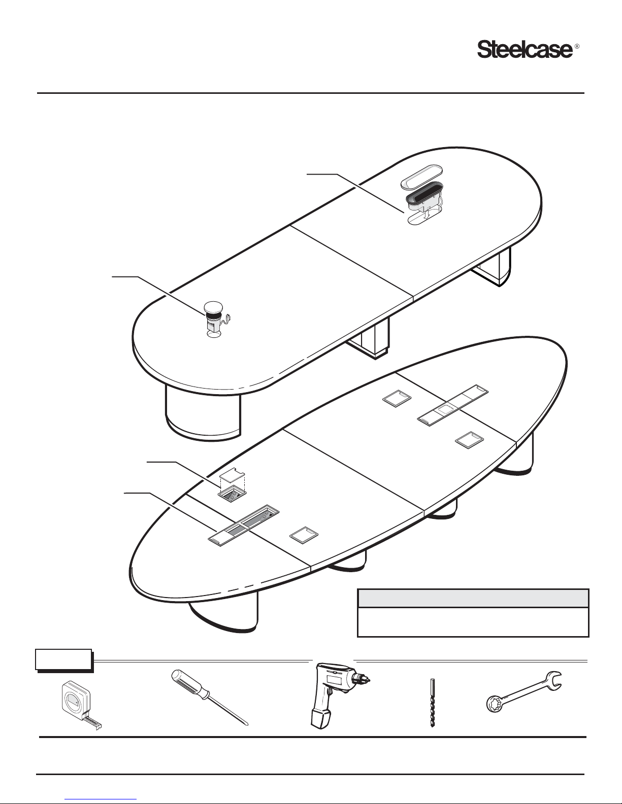
Convene - Sectional Table Top Assembly
RACETRACK TOP WITH ROUND
AND OVAL POWER PORTS
ROUND
POWER PORT
and Table Base Installation
OVAL
POWER PORT
POWER UNIT
POWER CHANNEL
TOOLS
4
7
8
0
8
6
4
8
9
Lufkin
R
3m/10'
Tape Measure
Assembly Directions
Screw Driver
Printed in U.S.A.
OVAL TOP WITH
POWER UNIT/CHANNEL
IMPORTANT NOTE
Install Power Unit/Power Channel before base.
(See Assembly Direction N9501956)
Power Driver
w/square tip
1/8"
Drill Bit
7/16” Wrench
Page1of11
N9501959 Rev. F
Setup
Check content of order to ensure all parts are accounted for
and components match.
Make sure you have the tools identified on front cover.
Install optional Power Unit/Power Channel to tops before
installing bases. (See Assembly Direction N9501956)
Ensure adequate work space is available for performing this
assembly and that table top surfaces are protected with clean
padded material such as shipping blankets.
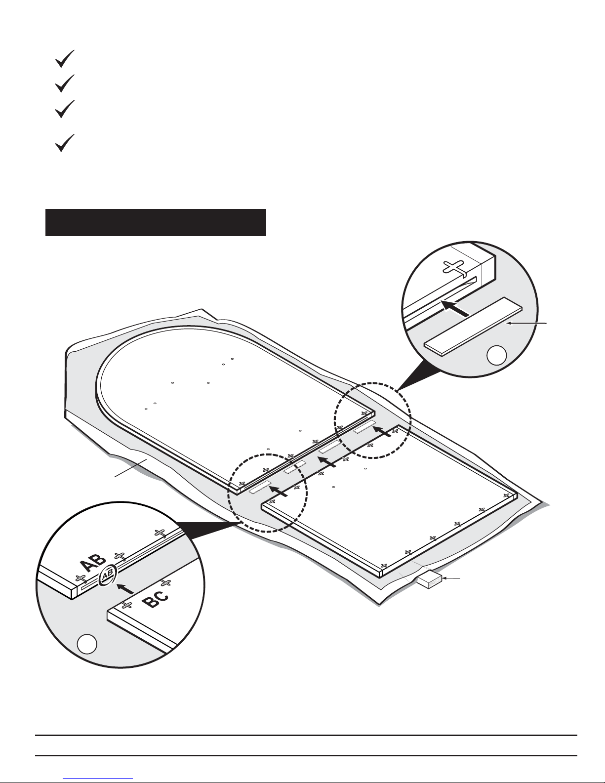
Sectional Top Assembly
1.
To ensure a uniform finish match, align
table top sections referring to match
marks on inside edge of top sections.
SPACER
PACKING
BLANKET
1.
2.
SHIM
TIP: Shims can be made
from the packing material
to elevate one edge of table
top and will allow for a finger
hold when assembly is
complete and top is
ready to upright.
Insert spacers into machine slot along top edge,
2.
spacing them equally along length.
Push table top sections together and check alignment.
N9501959 REV. F
DO NOT GLUE.
Steelcase
Page2of11
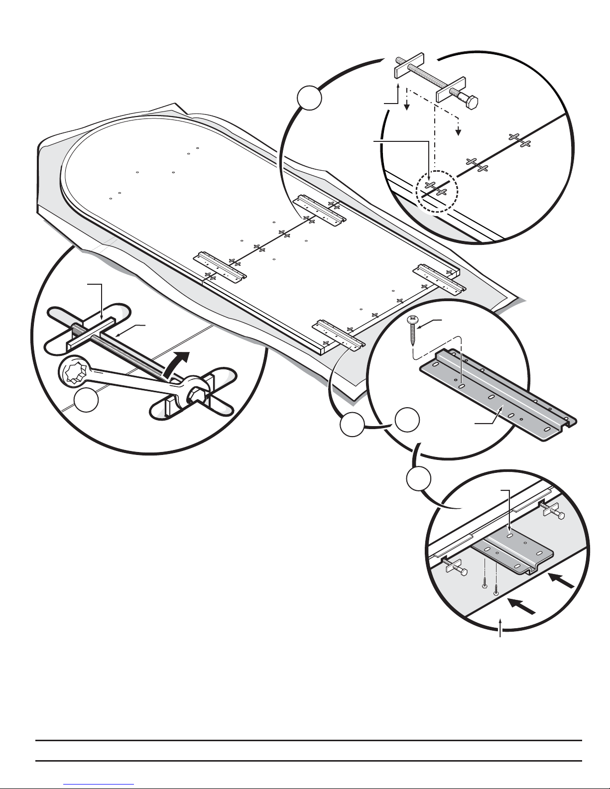
Put ‘T’ bolt connectors in each of the
3.
machined ‘T’ bolt slots. Tighten
bolts finger tight.
‘T’ BOLT
‘T’ BOLT
SLOT
3.
‘T’ BOLT
‘T’ BOLT
SLOT
#10 x 7/8”
SCREW
4.
7/16” WRENCH
4.
Using a 7/16” wrench, tighten ‘T’ bolts
5.
starting with bolts located closest to the
center of top and work outward. Continue
to repeat this process until all bolts are tight.
Attach hanger brackets (2) per section with
5.
#10 X 7/8” screws, (9) per bracket. Evenly
space brackets to the outside edge of top.
Do not cover T-Bolt slots or table base locations.
NOTE: When assembling tops having three or more sections,
completely assemble two sections separately. Attach hanger brackets
to one of the completed sections (see figure B), then upright assembled
sections to complete assembly.
A
HANGER
BRACKET
B
HANGER
BRACKET
TOP SHOWN IN
UPRIGHT POSITION
N9501959 REV. F
Steelcase
Page3of11
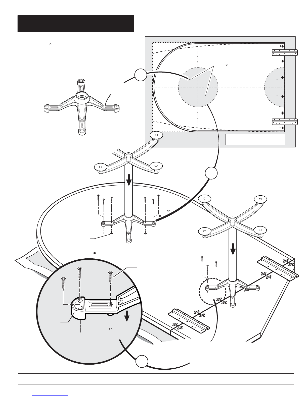
Positioning And Attachment Of
Table Bases With Spider Bracket
Locate 45 hole pattern on bottom
1.
of table top, then position spider
bracket base as shown.
Align pilot holes with
this hole in bracket.
SPIDER BRACKET
2.
Install (2) screws into pilot
holes, then drill pilot holes
for the other (10) screws.
45 hole pattern
1.
TWO PIECE RACETRACK TOP
(LOOKING DOWN AT BOTTOM)
Install screws into
these pilot holes.
2.
#10 x 1-3/4”
SPIDER
BRACKET
N9501959 REV. F
3.
Steelcase
3.
Secure table base with screws
(#10 X 1- 3/4”, 3 per foot).
Page4of11
 Loading...