

Stearns 36X Series Parts List
®
Armature Actuated Brakes
Installation, Service and Parts List for
36X Series Armature Actuated Brakes
P/N 8-078-898-00
effective 10/06/10
Important
Please read these instructions carefully before installing, operating,
or servicing your Stearns brake. Failure to comply with these
instructions could cause injury to personnel and/or damage to
property if the brake is installed or operated incorrectly. For
definition of limited warranty/liability, contact
(414) 272-1100.
OEM’s and subsystem suppliers, please forward these
instructions with your components to the final user.
Caution
Servicing shall be in compliance with applicable local safety 1.
codes including Occupational Safety and Health Act (OSHA). All
wiring and electrical connections must comply with the National
Electric Code (NEC) and local electric codes in effect.
To prevent an electrical hazard, disconnect power source before 2.
working on the brake. If power disconnect point is out of sight,
lock disconnect in the off position and tag to prevent accidental
application of power to system.
To avoid damage to internal power supply, hipot testing should 3.
not exceed 1500 volts for one second. Brake coil leads must be
connected together.
Heat developed during normal operation (135°C) of the brake 4.
may be hot enough to be painful or cause injury. Be careful
when touching exterior surfaces. Allow sufficient time for the
brake to cool before servicing.
After usage, the brake will contain burnt and degraded friction 5.
material dust. This dust should be removed before servicing or
adjusting the brake.
DO NOT blow off dust using an air hose. It is important to
avoid dispersing dust into the air or inhaling it, as this may be
dangerous to your health.
a) Wear a filtered mask or a respirator while removing dust.
b) Use a vacuum cleaner or a soft brush to remove dust from
the brake. When brushing, avoid causing the dust to become
airborne. Collect the dust in a container, such as a bag,
which can be sealed off.
Maximum continuous operating ambient temperature for these 6.
brakes should not exceed 40°C (104° F).
I. Installation
Note 1: Position of hub should allow full engagement of friction
disc without interfering with the movement of the armature. Motor
shaft end float should not exceed .020”. Shaft runout should
be within .002” TIR. Motor mounting surface should be flat
and perpendicular to within .004” of motor shaft.
Note 2: Keep grease and oil from contacting friction surfaces.
Note 3: Hub should be a tight sliding fit. For shrink fit hub,
consult factory.
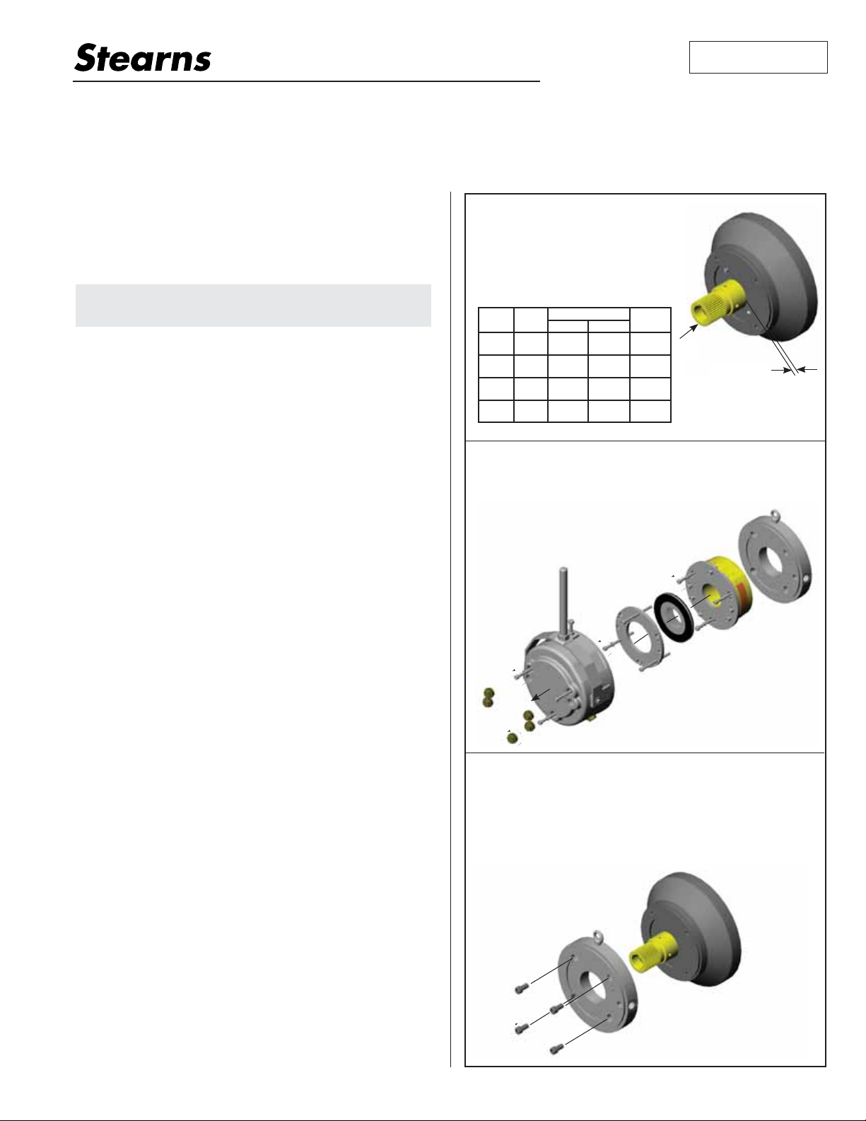
I. Installation
Step 1
Position hub and key on motor shaft (set 1.
screw end toward motor).
Locate hub 1/8” (±1/16”) outward from 2.
the register face.
Tighten set screws per Table A.3.
Table A
Brake
Bolt
Model
Circle
7.25
36X-6
9.00
7.25
36X-7
9.00
9.00
36X-8
11.00
11.00
36X-9
14.00
Step 2
Remove the three access plugs using a 22mm wrench.1.
Remove the three housing bolts using a 6mm hex 2.
wrench, and lift the housing from the brake.
Remove the three pressure plate bolts* and 3.
remove the pressure plate and carrier disc.
Remove the three magbody mounting bolts* 4.
and separate the magbody from the adapter plate.
2.
ccw x 3
1.
ccw x 3
Step 3
Position adapter plate on motor register.1.
Bolt adapter plate to motor register with four mounting bolts. (Not 2.
provided) (1/2-13 x 1.25” for 7.25 and 9.00” BC and 5/8-11 x 1.25”
for 11.00” BC. and 14.00” BC.) Tighten to manufacturers specification
using 3/8” hex wrench for 7.25” and 9.00 BC mounting. Use 1/2” hex
wrench for 11.00” BC and 14.00” BC. mounting.
Note: Verify that the O-ring gasket is in place on the motor side of the
adapter flange.
Bolt Torque
Metric English
32.5Nm 23lb-ft 3/16”
32.5Nm 23lb-ft 3/16”
32.5Nm 23lb-ft 3/16”
76.5Nm 52lb-ft 1/4”
3.
ccw
x 3
2.
1.
Hex
Wrench
4.
ccw
x 3
1.
1/8” Surface
flush to
register.
4.
3.
3.
* Note: Refer to Table B for
proper wrench size.
ccw
2
2.
cw x 4
2.
Installation procedure continued on reverse side.
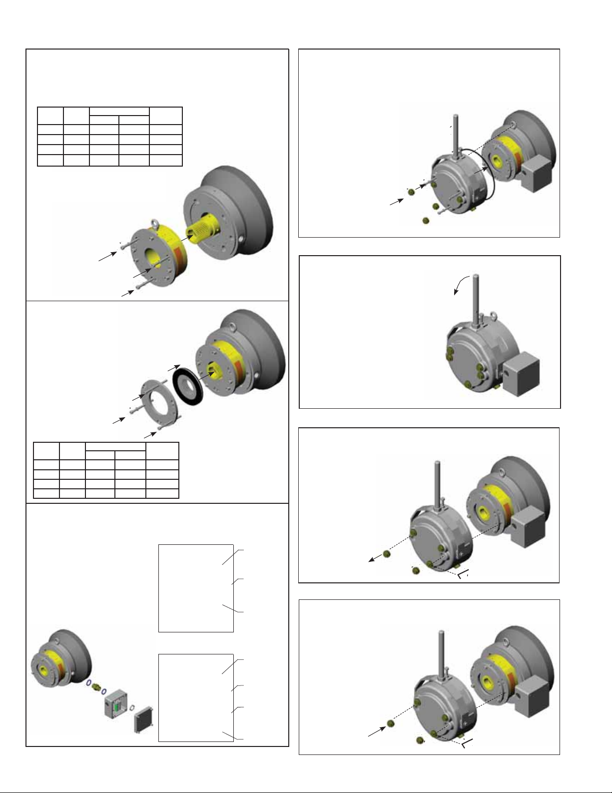
Installation continued
Installation continued
Step 4
Position armature/magbody assembly over hub and on to the adapter.1.
Tighten socket head cap screws per 2. Table B.
Table B
Brake
Bolt
Model
Circle
36X-6 170 38Nm 28 lb-ft 6mm
36X-7 196 38Nm 28 lb-ft 6mm
36X-8 230 68Nm 50 lb-ft 8mm
36X-9 278 68Nm 50 lb-ft 8mm
Bolt Torque
Metric English
Hex
Wrench
Note: Apply dry moly lube, or
anti-seize compound on bolt threads.
1.
2.
cw x 3
Step 5
Slide carrier disc onto the splined hub, with 1.
flat side of disc outward from motor.
Position pressure plate over carrier disc.2.
Tighten socket head cap screws per Table C.3.
Note 1: Apply dry moly
1.
lube, or anti-seize
compound on bolt threads.
Note 2: Verify air-gap as
2.
shown in Table D.
cw x 3
Table C
Brake
Bolt
Model
Circle
36X-6 170 19Nm 14 lb-ft 6mm
36X-7 196 38Nm 28 lb-ft 6mm
36X-8 230 68Nm 50 lb-ft 8mm
36X-9 278 68Nm 50 lb-ft 8mm
Bolt Torque
Metric English
Hex
Wrench
Note: Apply dry moly
lube, or anti-seize
compound on bolt
threads.
Step 6 Leadwire Connection Optional Conduit Box
Loosen NPT plug and four 1.
(4) cover plate screws from
junction box and remove.
Route leadwires into 2.
junction box and connect
conduit to box.
Connect wiring as shown 3.
for either the IP 56 or IP 65
conduit box assembly.
Replace junction box cover 4.
and tighten screws to seal.
5-08-0050-00
IP 56 Assembly
TERM BLOCK = LEADWIRES
1 = H1 YELLOW
2 = H2 YELLOW
Rexnord Corporation
3 = S1 RED-COMMON
8-078-760-00
4 = S2 WHITE - N.C
5 = S3 BLUE - N.O.
6 = B1 BLACK
7 = B2 BLACK
8 = 1 EMPTY
9 = 2 EMPTY
}
}
5-08-0051-00
IP 65 Assembly
TERM BLOCK = LEADWIRES
1 = H1 YELLOW
2 = H2 YELLOW
Rexnord Corporation
3 = L1 RED-COMMON
8-078-760-00
4 = L2 WHITE - N.C
5 = L3 BLUE - N.O.
6 = W1 RED-COMMON
7 = W2 WHITE - N.C
8 = W3 BLUE - N.O.
9 = B1 BLACK
10 = B2 BLACK
}
}
}
}
}
Optional
heater
leads
Optional
brake release
switch leads
Coil
leads
Optional
heater
leads
Optional
brake release
switch leads
Optional
brake wear
switch leads
Coil
leads
CAUTION: Be sure all internal wiring is clear of housing
flange before replacing housing.
Step 7
Slide housing over brake, align the manual release handle with the 1.
lifting lug position on the adapter plate. Verify that the O-ring gasket
is in position in the housing.
Insert the three housing 2.
bolts and tighten to 11 lb-ft
with a 6mm hex wrench.
Ensure that gasket is securely 3.
located on the face of the access
plug. Add a drop of Loctite 242, or
4.
cw
equivalent, to the thread of each
plug and tighten to 28 lb-ft using
a 22mm wrench.
Thread release handle into 4.
place and tighten jam nut
with a 30mm wrench.
3.
Insert and tighten the
stabilizing bolt against
2.
cw x 3
1.
the housing, and tighten
the jam nut using a
13mm wrench.
IIA Manual Release Operation (Deadman)
Loosen jam nut 1/2 turn, and stabilizing 1.
bolt one full turn, using a 13mm wrench.
Pull back on manual release handle.2.
Retighten stabilizing bolt and jam nut
when finished.
2.
1.
ccw
ccw
II Manual Release Engagement (Maintained)
Remove two manual release access 1.
plugs using a 22mm wrench.
Insert 6 mm hex wrench through 2.
housing and pressure plate.
Rotate release bolts cw 180°
at a time, alternating sides each
half turn, until armature is tight
against magnet body.
(You will feel bolts tighten).
1.
ccw x 2
cw
II Manual Release Disengagement (Maintained)
Insert 6mm hex wrench through housing and pressure plate. 1.
Rotate release bolts ccw 180° at a time, alternating sides each
half turn, until bolt head is tight against pressure
plate. (You will feel bolts tighten).
Then turn bolts cw 180°.
Ensure that gasket is 2.
securely located on the face
of the access plug. Add a
drop of Loctite 242, or
equivalent, to the thread
of each plug and tighten
to 28 lb-ft using a
22mm wrench.
1.
cw x 2
ccw
 Loading...