

Stearns 331 Series Parts List
®
Armature Actuated Brakes
Installation, Service and Parts List for 331 Series
Armature Actuated Brakes
331-7, 331-8, and 331-9
P/N 8-078-894-00
effective 05/13/13
Important
Please read these instructions carefully before installing, operating,
or servicing your Stearns brake. Failure to comply with these
instructions could cause injury to personnel and/or damage to
property if the brake is installed or operated incorrectly. For
definition of limited warranty/liability, contact
(414) 272-1100.
OEM’s and subsystem suppliers, please forward these
instructions with your components to the final user.
Caution
1. Servicing shall be in compliance with applicable local safety
codes including Occupational Safety and Health Act (OSHA). All
wiring and electrical connections must comply with the National
Electric Code (NEC) and local electric codes in effect.
2. To prevent an electrical hazard, disconnect power source before
working on the brake. If power disconnect point is out of sight,
lock disconnect in the off position and tag to prevent accidental
application of power to system.
3. To avoid damage to internal power supply, hipot testing should
not exceed 1500 volts for one second. Brake coil leads must be
connected together.
4. Heat developed during normal operation (135°C) of the brake
may be hot enough to be painful or cause injury. Be careful
when touching exterior surfaces. Allow sufficient time for the
brake to cool before servicing.
I. Installation
1
2
3
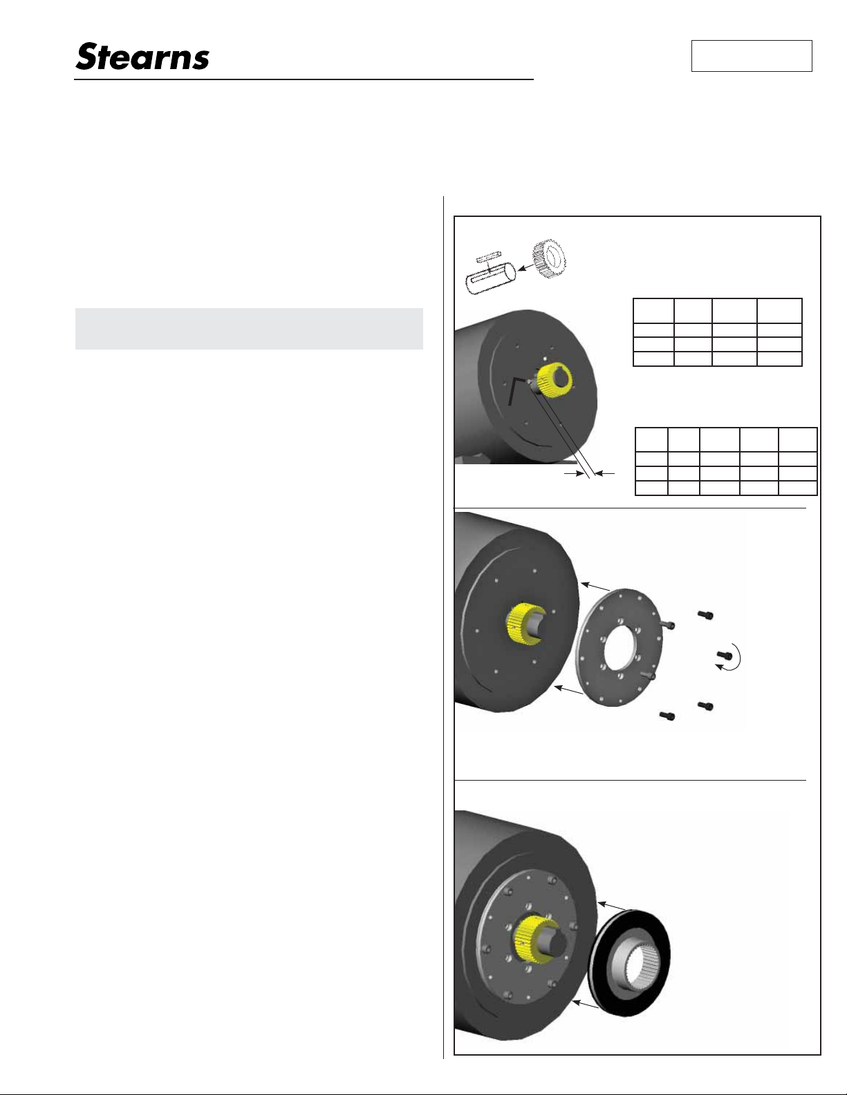
Step 1
1. Place key in motor shaft.
2. Position hub per Table A.
Table A (H2)
Brake
Model
331-7 196 14.5 mm .577”
331-8 230 15.7 mm .619”
331-9 278 17.2 mm .678”
3. Tighten set screws per
2
Table B
Brake
Model
331-7 196 32.5 Nm 24 ft-lb 3/16”
331-8 230 32.5 Nm 24 ft-lb 3/16”
H2
331-9 278 70.5 Nm 52 ft-lb 1/4”
Step 2
1. Bolt pressure plate to
motor register and torque
to manufacturer specifications.
Table B.
Bolt
Circle
Bolt
Circle
Metric English
Metric English
Wrench
Hex
5. After usage, the brake will contain burnt and degraded friction
material dust. This dust should be removed before servicing or
adjusting the brake.
DO NOT blow off dust using an air hose. It is important to
avoid dispersing dust into the air or inhaling it, as this may be
dangerous to your health.
a) Wear a filtered mask or a respirator while removing dust.
b) Use a vacuum cleaner or a soft brush to remove dust from
the brake. When brushing, avoid causing the dust to become
airborne. Collect the dust in a container, such as a bag,
which can be sealed off.
6. Maximum operating ambient temperature for these brakes
should not exceed 40°C (104° F).
I. Installation
Note 1: Position of hub should allow full engagement of friction
disc without interfering with the movement of the armature. Motor
shaft end float should not exceed .020”. Shaft runout should
be within .002” TIR. Motor mounting surface should be flat
and perpendicular to within .004” of motor shaft.
Note 2: Keep grease and oil from contacting friction surfaces.
Note 3: Hub should be a tight sliding fit. For shrink fit hub
consult the factory.
cw
x6
Note: Brakes without a manual release use armature retention
nuts and bolts that must be removed following mounting of the
brake to the motor.
Step 3
1. Align carrier disc with hub and
slide it into place against the
pressure plate.
* Manual release
is optional
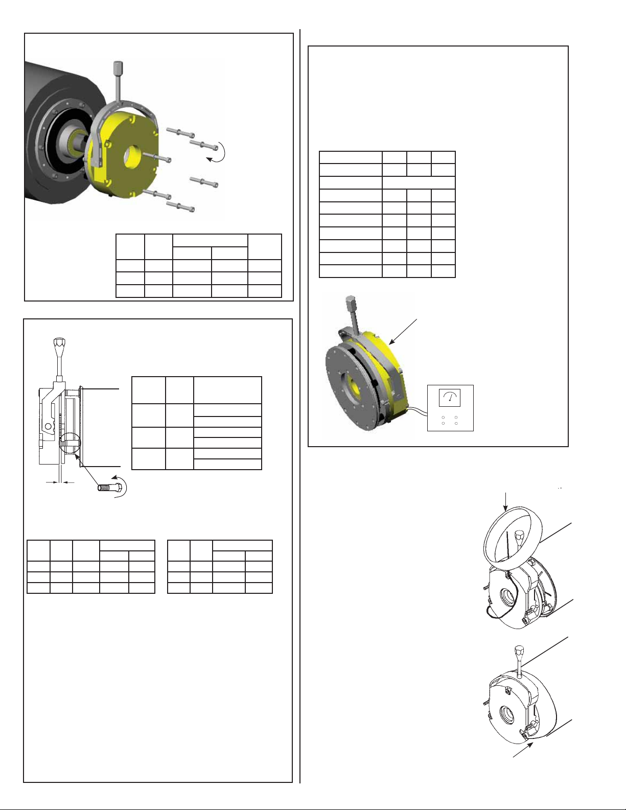
Step 4
1. Position brake assembly over
hub/carrier disc and slide up
against the pressure plate.
Tighten mounting bolts per
Table C.
cw
x6
Table C
Brake
Model
331-7 196 19 Nm 14 ft-lb 6 mm
331-8 230 38 Nm 28 ft-lb 8 mm
331-9 278 38 Nm 28 ft-lb 8 mm
Bolt
Circle
Mounting Bolt Torque
Metric English
Wrench
Hex
III. Coil Wiring
Caution: Brake wiring should only be carried out by qualified
*
personnel.
Stearns brake coils are wound for DC voltage input at
± 10%
of nameplate rating. Coil resistances shown below are for
references purposes. For applications where AC voltage is
being rectified refer to AC control switching shown on next
page.
Table J
Bolt 196 230 278
Brake Model 331-7 331-8 331-9
Voltage Rating Ohm (nominal value)*
24 7.28 5.62 5.11
90 110.3 85.4 77.9
103 138.2 107 97.7
180 426.8 330.7 302.6
205 534.6 414.3 379.3
258 669 650 605
414/432 1726 1649 1484
* Resistance values
at 20°C
II. Air Gap Setting and Wear Adjust
Air gap is factory set per Table D.
Figure 1
Bolt
Hex
Wrench
ccw
air gap
Table E - Maximum Air Gap
Brake
Model
Circle
331-7 196 3/4” .99 mm .035”
331-8 230 3/4” 1.24 mm .043”
331-9 278 3/4” 1.39 mm .055”
Set air gap is measured at the
adjusting bolts, between the armature
and magbody.
Table D - Minimum Air Gap
Brake
Model
331-7 196
331-8 230
331-9 278
Bolt
Circle
Air Gap with
Brake Release
Indicator Switch
.508-.610 mm
.020-.024”
.508-.610 mm
.020-.024”
.508-.610 mm
.020-.024”
Normal friction disc wear will
cause air gap to increase from
original setting (Table D). Air gap
should be readjusted when gap
reaches dimension shown in Table E.
Table F - Disc Maximum Wear
Max Gap
Metric English
Brake
Bolt
Model
Circle
331-7 196 9.27 mm 0.365”
331-8 230 11.68 mm 0.460”
331-9 278 12.57 mm 0.495”
Min. Thickness
Metric English
Coil voltage rating shown on
nameplate. Supply voltage must
be within 10% of nameplate rating.
DC ± 10%
IV. Boot Seal (Optional)
Note: For brake supplied with a boot seal, the seal
must be placed over the lead wires and manual release
before wiring the brake to the
power source.
1. Position the boot seal over the
manual release (if supplied) and
lead wires.
Wear Adjustment
1. Loosen six mounting bolts
1/2 turn.
2. Rotate three alternate
adjusting screws 1-1/2 turns
counter- clockwise.
3. Rotate three remaining
adjusting screws ccw to
achieve original gap
4. Retighten mounting bolts.
5. Recheck gap. Repeat
above procedures as
necessary.
6. Rotate three alternate
adjust screws clockwise
until snug with pressure
plate.
(Table D).
Note 1: 90° ccw rotation is approximately 0.38mm (0.015”)
air gap increase.
Note 2: Brake discs should be replaced when they reach the
thickness shown in Table F. Normally this will occur after 4-5
adjustments.
2. Stretch the seal over pressure
plate and magbody coil assembly.
If boot seal has optional drain hole,
place hole at bottom facing downward.
Check to make sure that the seal is
flat against the brake and covers the
open area around the brake.
 Loading...