

Stearns 1-087-8XX Catalog Page
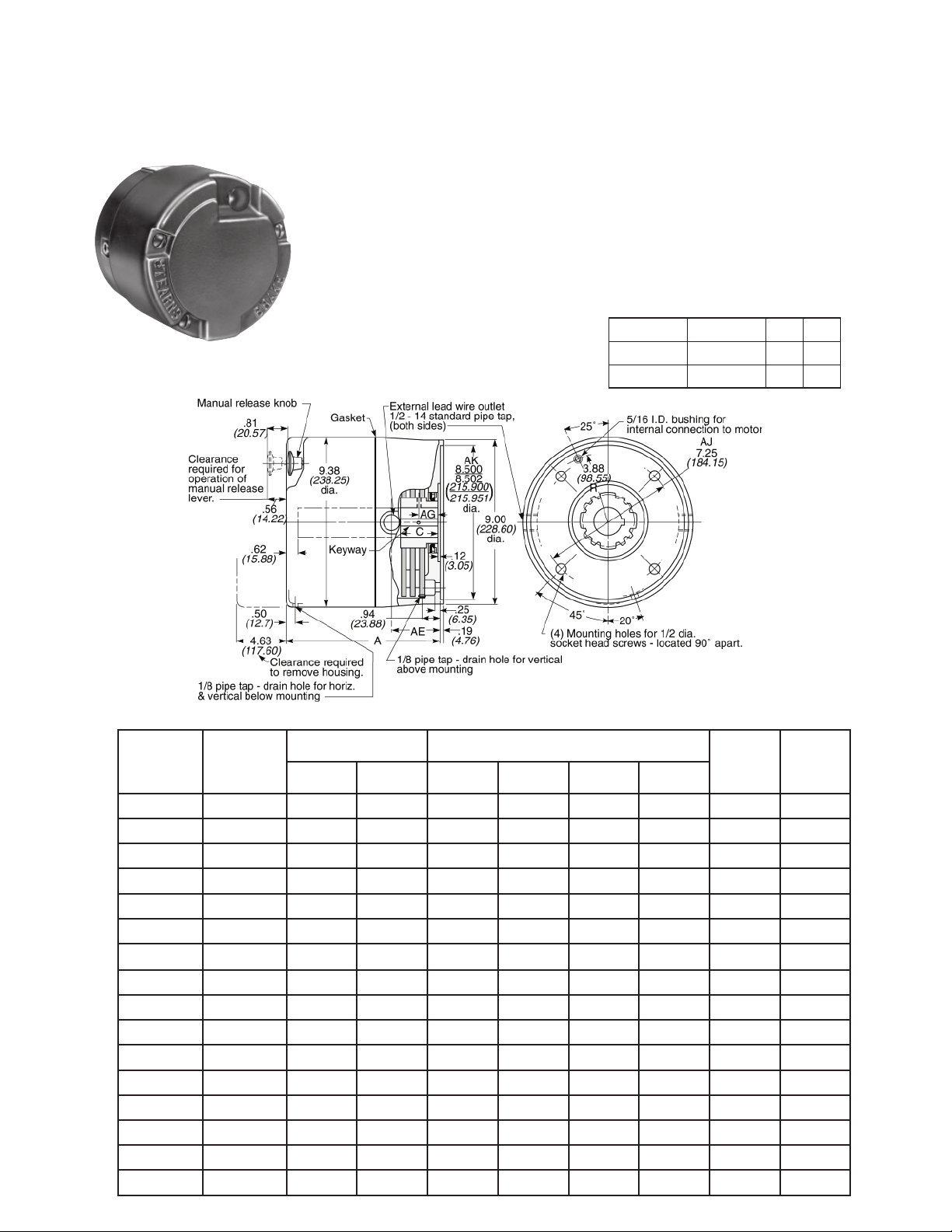
Series 87,800 (1-087-8XX)
Division 2 Hazardous Location
Mounting Face: NEMA 182TC 184TC, 213TC, 215TC, 254TC, 254UC,
256TC and 256UC
8.5” AK, 7.25” AJ
Static Torque: 6 through 105 lb-ft
Enclosure Material: Cast Iron
Release Type: Knob
Enclosure Protection: Type 4/IP 56
Division 2 Hazardous Duty
Certified: UL Listed, File E-14893.
For Hazardous Location Classification, see
Dimensional Data below.
Mounting Requirements: 1-87-8XX Series
Hazardous Location Motor Mounted Brake
is recommended for mounting close coupled
to the motor end bell. The acceptability of
the brake and motor combination must be
determined by Underwriters Laboratory.
Modification required for vertical above
mounting. For vertical below, modification
required on 50-105 lb-ft.
Epoxy Encapsulated Coil Construction, with
Class H Insulation
NC Thermostat
Maximum speed:
Horizontal 4000 rpm
Vertical 3000 rpm
ABS Type Approval Certified
Installation, Service & Parts List:
P/N 8-078-927-08
Brake set and release times, when brake
and motor are switched separately (
definitions, see page 101):
Static Torque Coil Size T1 T2
10, 15, 25, 50 5 & 6 42 20
35, 75, 105 8 48 20
BACK TO TABLE OF CONTENTS
for T1/T2
42
Dimensional Data
Model
Numbers
1-087-802-00
1-087-802-01
1-087-812-00
1-087-812-01
1-087-822-00
1-087-822-01
1-087-832-00
1-087-832-01
1-087-842-00
1-087-842-01
1-087-852-00
1-087-852-01
1-087-862-00
1-087-862-01
1-087-882-00
1-087-882-01
Nominal Static
Torque
lb-ft
(Nm)
(14)
(14)
(20)
(20)
(34)
(34)
(47)
(47)
(68)
(68)
(102)
(102)
105
(142)
105
(142)
(8)
(8)
10
10
15
15
25
25
35
35
50
50
75
75
Dimensions for estimating only. For installation purposes request certified prints.
Hazardous Location
Classification Division 2
Class I
Group -
6
6
A, B, C, D F, G
A, B, C, D F, G
A, B, C, D F, G
A, B, C, D F, G
A, B, C, D F, G
A, B, C, D F, G
A, B, C, D F, G
A, B, C, D F, G
Class II
Group -
F, G
F, G
F, G
F, G
F, G
F, G
F, G
F, G
AAEAGC
7.56
(192.02)
7.56
(192.02)
7.56
(192.02)
7.56
(192.02)
7.56
(192.02)
7.56
(192.02)
7.56
(192.02)
7.56
(192.02)
7.56
(192.02)
7.56
(192.02)
7.56
(192.02)
7.56
(192.02)
7.56
(192.02)
7.56
(192.02)
8.56
(217.42)
8.56
(217.42)
Dimensions in Inches
(Dimensions in Millimeters)
1.81
(45.97)
1.81
(45.97)
1.81
(45.97)
1.81
(45.97)
1.81
(45.97)
1.81
(45.97)
1.81
(45.97)
1.81
(45.97)
1.81
(45.97)
1.81
(45.97)
2.31
(58.67)
2.31
(58.67)
2.31
(58.67)
2.31
(58.67)
2.81
(71.37)
2.81
(71.37)
.78
(19.81)
.78
(19.81)
.78
(19.81)
.78
(19.81)
.78
(19.81)
.78
(19.81)
.78
(19.81)
.78
(19.81)
.78
(19.81)
.78
(19.81)
.97
(24.64)
.97
(24.64)
.97
(24.64)
.97
(24.64)
.97
(24.64)
.97
(24.64)
1.00
(25.4)
1.00
(25.4)
1.00
(25.4)
1.00
(25.4)
1.00
(25.4)
1.00
(25.4)
1.00
(25.4)
1.00
(25.4)
1.00
(25.4)
1.00
(25.4)
1.50
(38.10)
1.50
(38.10)
1.50
(38.10)
1.50
(38.10)
2.00
(50.80)
2.00
(50.80)
Enclosure
IP 56
IP 56
IP 56
IP 56
IP 56
IP 56
IP 56
IP 56
IP 56
IP 56
IP 56
IP 56
IP 56
IP 56
IP 56
IP 56
Wt.
lbs
(kg)
42
(19.1)
42
(19.1)
42
(19.1)
42
(19.1)
43
(19.5)
43
(19.5)
43
(19.5)
43
(19.5)
46
(20.9)
46
(20.9)
42
(19.1)
42
(19.1)
50
(22.7)
50
(22.7)
50
(22.7)
50
(22.7)
Series 87,800 continued
BACK TO T ABLE OF CONTENTS
Motor Frame Adapters:
WARNING! Before selecting an adapter to mount a brake on a larger motor
frame, the torque and thermal capacity required by the application should be
determined as shown in the “Selection Procedure” section. A larger motor may
indicate a requirement for greater thermal capacity than the brake is designed
for. The brake selection must be matched to the motor and application
requirements, before use of an adapter is considered.
To Adapt
to NEMA
Frame Size
56C, 143TC
or 145TC
284 TC or
286TC
324TC,
326TC,
364TC,
365TC,
404TC or
For adapter dimensions, see Technical Data.
AK
Dim.
in.
(mm)
4.50
(114.30)
10.50
(266.70)
12.50
(317.50)
Reg.
No.
Brake endplate is modified
for 4.50 in. AK. An adapter
is not furnished.
Add: $340.00
-05
-11 5-55-7055-00
-13 5-55-7046-00
Adapter
Stock
Number
5-55-7043-00
Additional Shaft
Length Required
in.
(mm)
—
(—)
.56
(14.22)
.81
(20.64)
.88
(22.22)
Current Ratings (amperes)
Coil
Size
5
6
8
Voltage: 60 Hz Voltage: 50 Hz
AC
Current
holding
holding
holding
115 200 230 400 460 575 110 220 380
inrush
7.5
4.3
3.7
2.2
1.9
.1
3.2
.2
4.2
.3
1.5
.09
2.6
.1
3.5
.3
inrush
inrush
.5
13.0
.6
17.6
1.2
.3
7.5
.4
10.3
.7
.2
6.5
.3
8.8
.6
.1
3.7
.2
5.0
.3
5.4
.3
9.4
.5
15.4
.1
4.0
.25
5.6
.3
7.7
.5
1.9
.1
3.2
.2
4.2
.3
Engineering Specifications
Nominal
Static
Torque
(Nm)
(102)
(142)
1
Maximum solenoid cycle rate is based on ambient temperature of 104°F
(40°C) with 50% duty cycle. Does relate to brake cycle rate (see Thermal
Capacity).
2
Thermal capacity rating is based on ambient temperature of 104° (40°C), stop
time of ne second or less, with no heat absorbed from motor. Derate thermal
capacity by 25% for vertical mounting. Refer to Selection Procedure Section.
lb-ft
(8)
10
(14)
15
(20)
25
(34)
35
(47)
50
(68)
75
105
No. of
Friction
Discs
6
1 5 4
1 5 4
1 6 4
1 6 4
1 8 4
2 6 4
2
3
Coil
Size
8
8
Maximum
Solenoid
Cycle Rate
cycles/
min
4
4
Thermal
Capacity 2
1
hp-sec/min
(watts)
14
(174)
14
(174)
14
(174)
14
(174)
14
(174)
14
(174)
14
(174)
14
(174)
Inertia (Wk2)
2
lb-ft.
(kgm2 x 10-4)
.048
(20.34)
.048
(20.34)
.048
(20.34)
.048
(20.34)
.048
(20.34)
.089
(37.40)
.089
(37.40)
.129
(54.45)
Ordering and Identification Information
The following example and tables provide information for
selecting the appropriate three-letter suffix when ordering
a Stearns Brake.
Example of a complete part number:
1-087-832-01-ELF Lead wire position (internal and
external, left and right)
460 Vac
1-1/8 bore and 1/4 x 1/8 keyway
Hub Selection
Bore
Character
A*
B*
C*
D
E
F
G
H
I*
K*
L*
M*
N*
O*
P*
Q*
R*
S*
T*
U*
Maximum allowable bore 1.625.
1-1/16
1-7/16
1-3/16
1-5/16
Z
* These bores are non-standard.
Keyseats made to ANSI B17.1 standard.
**
Standard AC
Voltage Ratings
Character Voltage Hz
B 115 60
D 110 50
E 200 60
F
H 220 50
L
M 415 50
N 575 60
O 110/220 50
P 115/230 60
230/460
Q
R 200/400 60
Modifications are available- see SAB Modification Section
Optional Space Heater for Class II Brakes only
(in.)
5/8
5/8
3/4
7/8
1-1/8
1-1/4
1-3/8
1-5/8
1-3/4
1/2
1
1-1/2
9/16
11/16
13/16
15/16
.600
230
190
460
380
230
Keyway**
(in. x in.)
1/8 x 1/16
3/16 x 3/32
3/16 x 3/32
3/16 x 3/32
1/4 x 1/8
1/4 x 1/8
5/16 x 5/32
3/8 x 3/16
3/8 x 3/16
1/8 x 1/16
1/4 x 1/8
3/8 x 3/16
1/8 x 1/16
3/16 x 3/32
1/4 x 1/8
3/8 x 3/16
3/16 x 3/32
1/4 x 1/8
1/4 x 1/8
5/16 x 5/32
pilot bore
60
50
60
50
60
50
43
 Loading...