

Stearns 1-056-600 Series Parts List
®
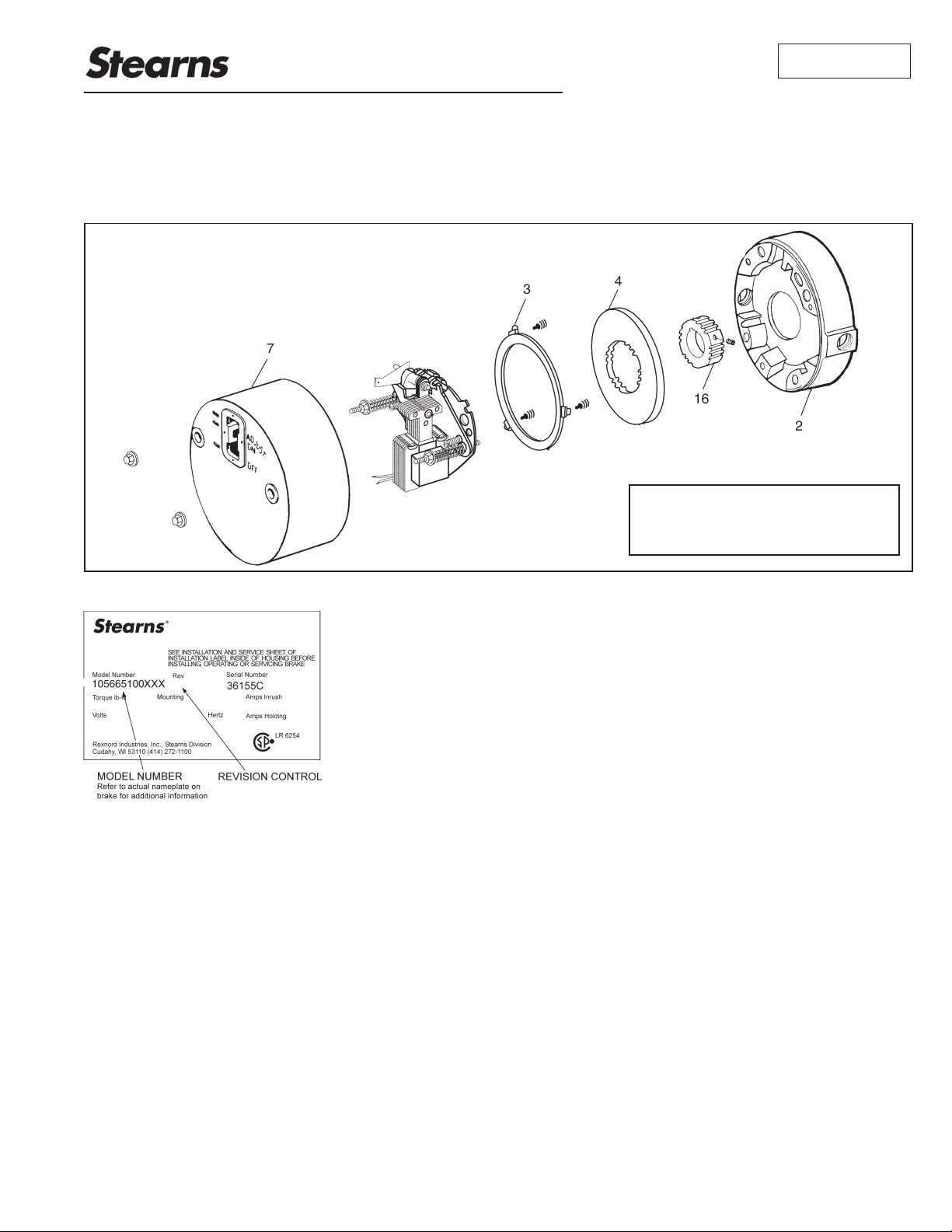
Spring-Set Disc Brakes
Parts List
for 1-056-600 Series (rev. A & B)
Manual Adjust Brakes
P/N 8-078-906-06
effective 05/02/14
For Installation and Service Instructions
refer to sheet part number 8-078-905-60.
Instructions and parts list also available at
Tools required for installation and servicing:
3/8” hex wrench 5/16” nut driver
5/16” hex wrench 1/4” screwdriver
3/16” hex wrench 8” adjustable wrench
Typical Nameplate
IMPORTANT
Please read these instructions carefully
before installing, operating, or servicing
your Stearns Brake. Failure to comply
with these instructions could cause
injury to personnel and/or damage
to property if the brake is installed or
operated incorrectly. For definition of
limited warranty/liability, contact Rexnord
Industries, Inc.,
Cudahy, WI
53110, (414) 272-1100.
Caution
1. Installation and servicing must be
made in compliance with all local
safety codes including Occupational
Safety and Health Act (OSHA). All
wiring and electrical connections must
comply with the National Electric
Code (NEC) and local electric codes
in effect.
2. Do not operate the brake in
atmospheres containing explosive
gases or dusts.
3. To prevent an electrical hazard,
disconnect power source before
working on the brake. If power
disconnect point is out of sight, lock
disconnect in the off position and tag
to prevent accidental application of
power.
4. Make certain power source conforms
to the requirements specified on the
brake nameplate.
5. Be careful when touching the
exterior of an operating brake. Allow
sufficient time for brake to cool before
disassembly. Surfaces may be hot
enough to be painful or cause injury.
6. Do not operate brake with housing
removed. All moving parts should be
guarded.
7. Installation and servicing should be
performed only by qualified personnel
familiar with the construction and
operation of the brake.
8. For proper performance and
operation, only genuine Stearns
parts should be used for repairs and
replacements.
9. After usage, the brake interior will
contain burnt and degraded friction
material dust. This dust must be
removed before servicing or adjusting
the brake.
DO NOT BLOW OFF DUST using an air
hose. It is important to avoid dispersing
dust into the air or inhaling it, as this may
be dangerous to your health.
a. Wear a filtered mask or a respirator
while removing dust from the inside of
a brake.
b. Use a vacuum cleaner or a soft brush
to remove dust from the brake. When
brushing, avoid causing the dust to
become airborne. Collect the dust in
a container, such as a bag, which can
be sealed off.
1
Information required when ordering replacement parts:
• Give Part Number of parts or kits needed, Brake Model Number,
and Brake Serial Number. The Brake Model and Serial Number
may identify special brakes not covered by this parts list
• When ordering hubs, specify shaft diameter (hub bore) and
keyway.
• Enclosure is specified as follows:
• NEMA 2 (formerly referred to as standard)
• NEMA 4 (formerly referred to as DTWP dust-tight waterproof)
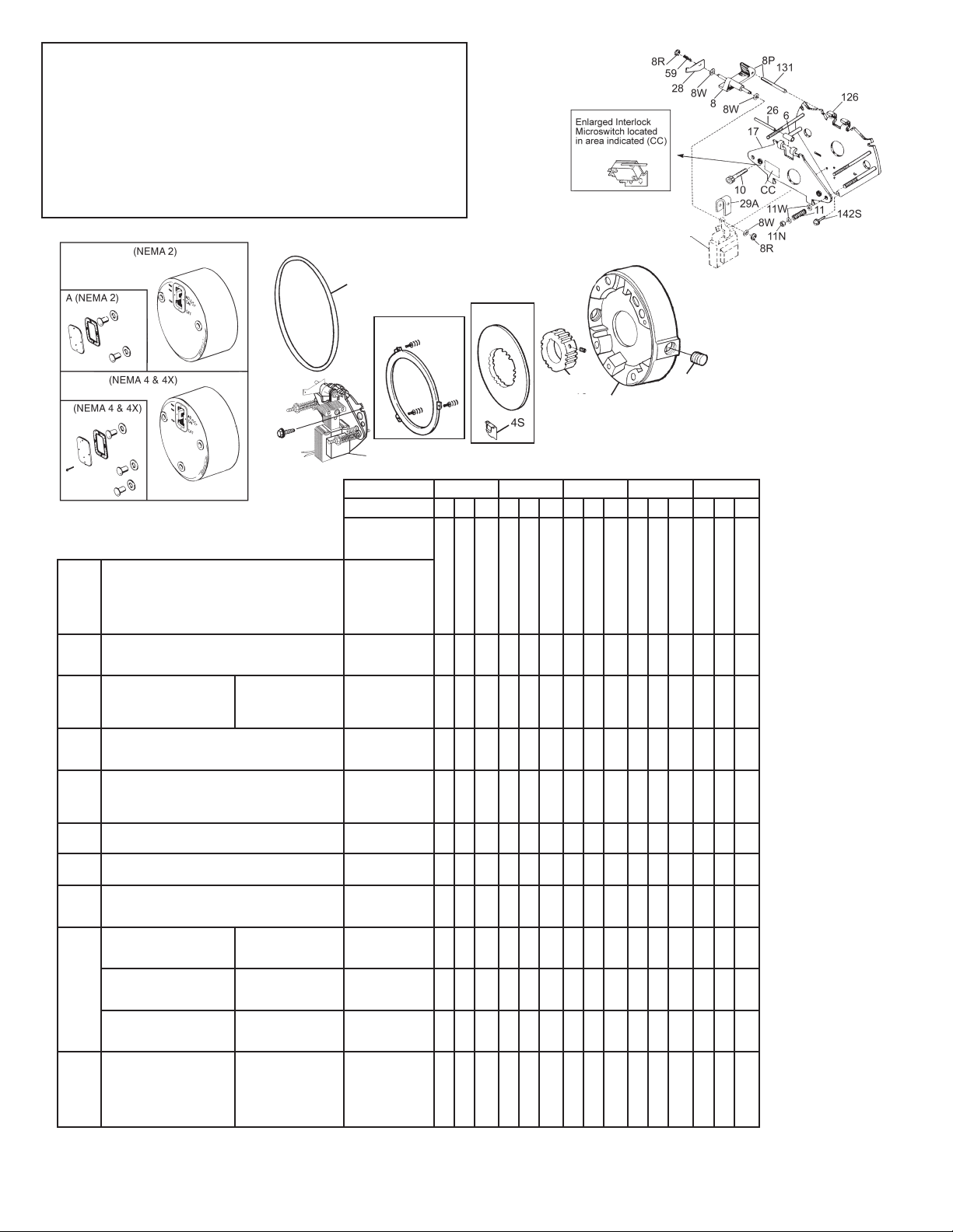
7
A (NEMA 4 and 4X)
AA
3 (3A & 3B)
Support Plate
Assembly
Solenoid and
Coil Assembly
4
7
7
Torque (lb-ft) 1.5 and 3 6 10 15 20 and 25
NEMA Enclosure 2 4 4X 2 4 4X 2 4 4X 2 4 4X 2 4 4X
TABLE 1
Components of Standard AC or DC Brake
Item Description
A Hardware kit - NEMA 2
Hardware kit - NEMA 4
Hardware kit - NEMA 4X
AA Plug/Gasket kit
**Close couple
7 Housing ─ NEMA 2
Housing ─ NEMA 4
Housing ─ NEMA 4X
3
Stationary disc kit (1 disc universal
3 disc horizontal)
3A
Stationary disc kit (2 disc universal)
3B
Stationary disc kit (3 disc horizontal)
Not
Vertical spring kit (3 disc) 5-63-0525-00 1 1 1
Shown
44CFriction disc kit
Stabilizing clip (part of 5-66-8462-00)
Disc pack kit ─ 1 disc
DP
Disc pack kit ─ 2 disc
Disc pack kit ─ 3 disc
Hub and set screw assembly
1 & 2 disc (NEMA 2)
Hub and set screw assembly
16
1 disc (NEMA 4 & 4X)
Hub and set screw assembly
3 disc (NEMA 2)
2 and 3 disc (NEMA 4 & 4 X)
Endplate
Endplate
Endplate & seal assembly
2
Endplate & seal assembly
Endplate & seal assembly
Endplate & seal assembly
─ NEMA 4
─ NEMA 4X
─ NEMA 4 3 disc
─ NEMA 4X 3 disc
5/8 bore
7/8 bore
1-1/8 bore
5/8 bore
7/8 bore
1-1/8 bore
5/8 bore
7/8 bore
1-1/8 bore
1 disc (NEMA 2)
2 & 3 disc (NEMA 2)
1 disc (NEMA 4)
2 & 3 disc (NEMA 4)
1 disc (NEMA 4X)
2 & 3 disc (NEMA 4X)
Brake Model
Number
Part Number
5-66-1011-00
5-66-1012-00
5-66-1013-00
5-63-0532-00
5-63-0533-00
5-63-0534-00
5-63-0535-00
8-007-509-20
8-007-509-21
8-007-509-23
5-66-8354-00
5-66-8355-00
5-66-8356-00
5-66-8462-00
5-66-8601-00
5-66-8602-00
5-66-8603-00
5-16-5150-00-01B
5-16-5150-00-01D
5-16-5150-00-01E
5-16-5151-00-01B
5-16-5151-00-01D
5-16-5151-00-01E
5-16-5153-00-01B
5-16-5153-00-01D
5-16-5153-00-01E
8-002-580-01-30F
8-002-582-01-30F
5-02-5043-00
5-02-5044-00
5-02-5045-00
5-02-5046-00
1-056-601-00 & -611-00
1-056-602-00 & -612-00
1-056-604-00 & -614-00
1-056-621-00
1
1
111 111
1212121
111 111
1
1
1
1
1
1
1
1
1
1
1
1
21212
1
1
1
1
1
1
1
1
1
1
1
1
16
2
1-056-622-00
1-056-624-00
1-056-631-00
1-056-632-00
1-056-634-00
1-056-641-00
1
1
1
1
1
1
1
1
111111
2*2*2*2*2*2*3*3*3
111111
1
1
1
1
1
1
1
1
1
1
1
1
1
1
1
1
1
1
1
1
1
1
1
1
1
1
1
1
1
1
1
1
A
AA
1-056-642-00
1-056-644-00
1
1
1
1
1
1
1
1
1
1
1
1
1
1
1-056-651-00 & -661-00
1-056-652-00 & -662-00
1-056-654-00 & -664-00
1
1
1
1
1
1
1
1
31313
1
*
11 1
1
1
1
1
1
1
1
1
1
1
1
1
* Certain multiple friction disc model numbers require a single stabilizer clip (D1) added to each friction disc. If your particular brake model has this clip
on the discs, as received, it must be replaced whenever the friction disc is replaced. This clip is included as part of the friction disc kit 5-66-8462-00.
** Close coupled brakes are identified by an 8 in the 8th digit. Example: 1-056-XXX-8X.
2
 Loading...