

Page 1
Revised March 2011
©2011 State Industries
Page 2
PUMP
TA N KS
™
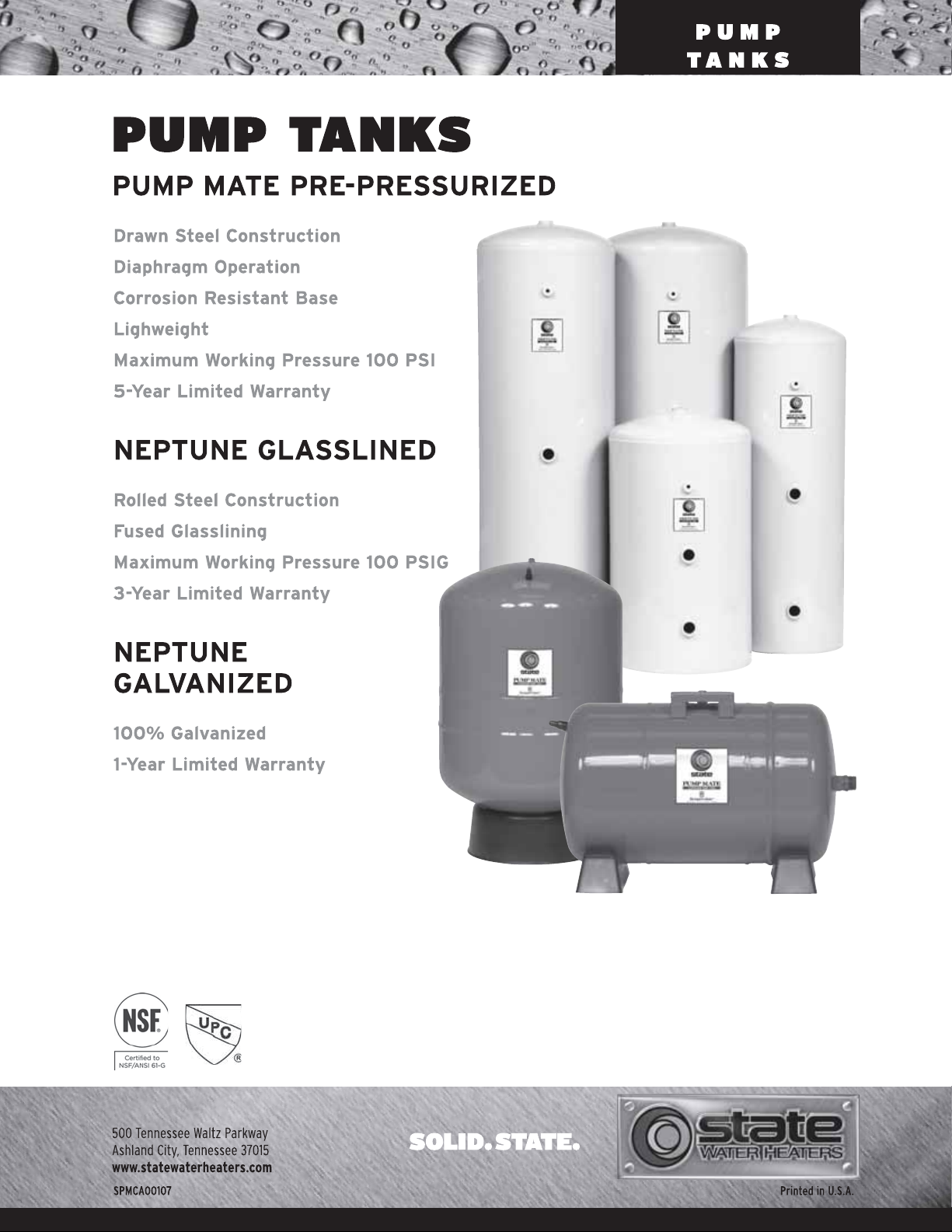
PUMP MATE
PRE-PRESSURIZED DIAPHRAGM OPERATION
5-YEAR LIMITED WARRANTY
State Industries Pump Mate tanks are designed for installation flexibility and years of trouble-free service. Smooth,
dependable diaphragm design and operation provides precise
control of system operation cycles. Free-standing and in-line
vertical tanks are available, as well as horizontal tanks with
universal pump mounting bracket. Every State Pump Mate
tank is made in the U.S.A.
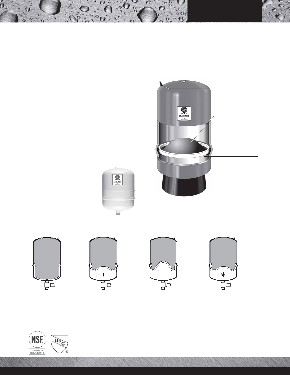
Higher Drawdown Than
Competition!
Convenient Air Charge Valve.
Butyl Diaphragm ensures
permanent separation of air
and water. Steel retaining
ring “seals” diaphragm
directly to tank shell.
The industry's most popular “standard” tank sizes are
44-gallon. Pump Mate offers 52-gallon tanks in the same
price range. So, a 52-gallon Pump Mate delivers 12%
higher drawdown than the industry standard. A 52-gallon
Pump Mate delivers 18% higher drawdown than standard!
In-Line Tanks
SPMDI Series tanks, available in 2, 4.6,
7.3 and 14-gallon sizes, are designed to
be supported by system piping (See
Typical Installations, page 4).
2-coat polymer water-side
lining, bonded to shell,
proven protection
against rust.
Rotating corrosion-resistant base
assures stability. Rotates for
easy alignment to connection.
Slotted and notched for proper
airflow, reduced condensation.
PRE-PRESSURIZED PUMP TANK OPERATION CYCLES
38 PSI
50 PSI
28 PSI
40 PSI
Start-up Cycle*
Diaphragm is pressed against
the bottom of the chamber.
* Based on 30-50 PSI operating system.
2
Fill Cycle*
Water is pumped into the reservoir, which forces the diaphragm
upward into the air chamber.
Hold Cycle*
Pump-cutoff pressure is attained.
Diaphragm reaches its uppermost
position. Reservoir is now filled to
its rated capacity.
Delivery Cycle*
Pump remains shut off while air
pressure in top chamber forces
diaphragm downward, delivering
water to syste m.
Page 3
PUMP
TA N KS
™
PUMP MATE
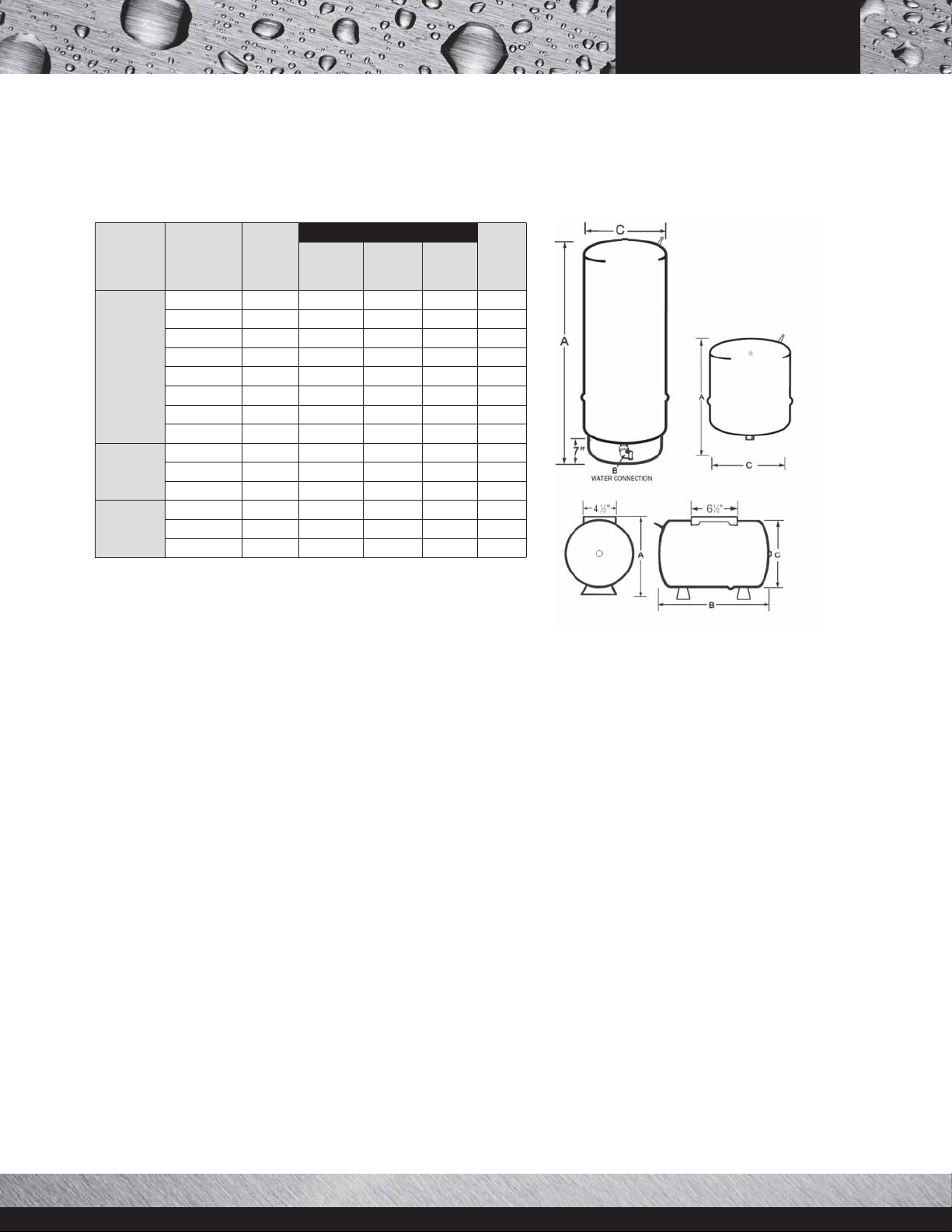
PRE-PRESSURIZED DIMENSIONS AND WEIGHTS
Dimensions in Inches
SPMD
Series
Free
Standing
SPMDI
Series
In-Line
SPMDH
Series
Horizontal
Model Number
SPMD-14
SPMD-20
SPMD-31
SPMD-36S
SPMD-52
SPMD-86
SPMD-96
SPMD-119
SPMDI-2
SPMDI-5
SPMDI-7
SPMDH-7
SPMDH-14
SPMDH-20
Vol um e
(Gallons)
14.0
20.0
31.0
36.0
52.0
86 59
96.0
119.5
2.0
4.6
7. 3
7. 3
14.0
20.0
“A”
Overall
Height
243⁄
323⁄
451⁄
325⁄
385⁄
633⁄
611⁄
103⁄
143⁄
211⁄
127⁄
173⁄
173⁄
4
4
2
8
8
8
4
16
4
16
8
8
8
“B” To
Center of
Water Inlet
21⁄
21⁄
21⁄
21⁄
21⁄
21⁄
21⁄
21⁄
—
—
—
211⁄
213⁄
271⁄
SPMD-14, SPMD-20, SPMD-36S connection 1" Female.
SPMD-52, SPMD-86, SPMD-96, SPMD-119 connection 1-1⁄4" Female.
SPMDI connection3⁄4" Male. • SPMDI-14 1" male.
SPMDH-7 connection3⁄4" Male. * SPMDH-14, SPMDH-20 connection 1" Male.
4
4
4
4
4
4
4
4
16
4
8
Diameter
153⁄
153⁄
153⁄
233⁄
233⁄
233⁄
81⁄
153⁄8251⁄
153⁄
Weight
“C”
(Lbs.)
8
8
8
20
8
105
8
8
26 160
4
11 9
11 12
11
8
25
30
40
45
77
111
5
16
2
30
3
Page 4

PUMP TANK SIZING
PUMP
TANKS
Free-Standing
Chart 1- PMD Series Free-Standing Tank Selection Chart
Selection
Charts
The charts below allow you
to easily select the right
free-standing tank for standard size pumps between
2-1/2 and 30 gallons in
capacity and for 20-40 PSI,
30-50 PSI and 40-60 PSI
pressure ranges. Minimum
run times shown (from
start-up) are 1 minute, 11/2 minutes and 2 minutes. For example, for a system that delivers 10 gpm at
30-50 PSI, with a minimumruntimeof1
minute, Chart 1 indicates
that the proper tank is the
SPMD-36S.
If proper tank
selection can-
Pump
GPM
1
2.5 SPMD-14 SPMD-14 SPMD-14 SPMD-14 SPMD-14 SPMD-20 SPMD-14 SPMD-20 SPMD-20
5 SPMD-14 SPMD-20 SPMD-36S SPMD-20 SPMD-36S SPMD-36S SPMD-20 SPMD-36S SPMD-52
7 SPMD-20 SPMD-36S SPMD-52 SPMD-36S SPMD-36S SPMD-52 SPMD-36S SPMD-52 SPMD-86
10 SPMD-36S SPMD-52 SPMD-86 SPMD-36S SPMD-52 SPMD-86 SPMD-52 SPMD-86 SPMD-86
12 SPMD-36S SPMD-52 SPMD-86 SPMD-52 SPMD-86 SPMD-86 SPMD-52 SPMD-86 SPMD-96
15 SPMD-52 SPMD-86 SPMD-86 SPMD-52 SPMD-86 SPMD-119 SPMD-86 SPMD-96 SPMD-119
20 SPMD-86 SPMD-86 SPMD-119 SPMD-86 SPMD-119 [2]SPMD-86 SPMD-86 SPMD-119 [2]SPMD-86
25 SPMD-86 SPMD-119 [2]SPMD-86 SPMD-86 [2]SPMD-86 [2]SPMD-86 SPMD-96 [2]SPMD-86 [2]SPMD-96
30 SPMD-86 [2]SPMD-86 [2]SPMD-86 SPMD-119 [2]SPMD-86 [2]SPMD-119 SPMD-119 [2]SPMD-96 [2]SPMD-119
Chart 2- Drawdown Volume Multiplier (Approximate)
Pump
Shut-Off
Pressure
10 20 30 40 50 60 70 80
Psi
20 0.26
30 0.41 0.22
40 0.37 0.18
50 0.46 0.31 0.15
60 0.40 0.27 0.13
70 0.47 0.35 0.24 0.12
not be made
using Chart 1,
follow this procedure .
First find the “drawdown multiplier” by matching the
pump start-up and shut-off pressures on Chart 2. For
example, the multiplier for a 30-50 PSI pressure range
is .31. Next, insert the pump GPM capacity and
desired minimum run time into this formula:
PUMP GPM x Min. Run Time
Multiplier
To assume dependable Drawdown Volumes, and in
keeping with present industry practice, Drawdowns
are based on Boyles Law.
For example, using a 10 GPM pump, a one-minute
minimum run time, and a 30-50 PSI pressure range,
the formula is as follows:
10 x 1
.31
32.25 Minimum Tank Volume
=
Then, using Chart 3, select the tank that has a minimum volume that meets or exceeds your minimum
volume requirement, and supplies adequate drawdown at the required pressure range. Minimum drawdown equals Pump GPM x Minimum Run Time.
Therefore, in the above example, select the SPMD36S 36-gallon tank. It provides adequate drawdown at
30-50 PSI.
Minimum Tank
=
Volume Required
System Pressure Ranges-PSI
20-40
1-1/2
Minimum Run Times (Minutes)
2 1
30-50 40-60
1-1/2
2 1
1-1/2
Chart 3- Drawdown in Gallons
Pump Start-Up Pressure-PSI
Model No.
SPMDI-2 2.0 0.7 0.6 —
SPMDI-5 4.6 1.7 1.4 —
SPMDI-7 7.3 2.7 2.3 —
SPMD-14 14.0 5.2 4.3 3.8
SPMD-20 20.0 7.4 6.2 5.4
SPMD-31 31 11.4 9.6 8.4
SPMD-36S 36.0 13.3 11.2 9.7
SPMD-52 52.0 19.2 16.1 14.0
11.012.023.024.008
SPMD-86 86.0 31.8 26.7 23.2
SPMD-96 96.0 35.5 29.8 25.9
01.091.092.083.084.009
SPMD-119 119.5 44.2 37.0 32.3
71.062.053.044.0001
Vol . i n
Gallons
20-40 30-50 40-60
Rule of Thumb Sys tem Sizing
The following water requirements figures are based on averages accepted by
the industry. They represent typical household and farm animal water use
requirements. Generally speaking, a reliable daily average water requirement is
100 gallons per day per person.
Average home water requirements based on
Average daily farm animal
requirements
Gallons/Day
Horse, Mule, Steer 12
Cow-Dry 15
Cow-Milking 35
Hog 4
Sheep 2
Chicken/100 6
Turkey/100 20
Average household water requirements (GPM) using industry-accepted 7-minute peak
demand cycle
No. of
Bathrooms
1 Sink, Toilet, Lavatory Tub/Shower 7
2
11⁄
Same as Above but with Automatic Washer 10
2
2-21⁄
Same as Above but with Automatic Dishwasher 14
3-4 Same as Above 17
industry-accepted 7-minute peak demand cycle
Unit
Kitchen sink 5 3
Toilet 4 5
Lavatory 4 2
Tub or Shower 5 35
Auto Wash Machine 5 35
Dishwasher 2 14
Garden Hose (1⁄2") 3
Lawn Sprinkler 3-7
Water Softener 7
Type of Water Using Fixtures Installed
Flow Rate
GPM
Requirement
Gallons
Depends
upon
{
cycle time
GPM
Required
2
4
Page 5

PUMP
TANKS
TYPICAL INSTALLATIONS
F or multiple installations, manifold size is critical. If you have questions about sizes call our
Technical Engineering Services Department at 1-800-36 5-002 4.
Free-Standing Series*
The standard installation, utilizing front entry, with gauge, relief
valve and pressure switch installed in
front
of tank.
Free-Standing Series With
Pump Mounted On Tank*
The pump can be mounted on tank using a universal
mounting base. The pump and base can be strapped to
the tank in the horizontal position, or mounted to the
tank in a vertical position.
In-Line Series*
The In-Line Series is designed to be supported by
system piping, either directly above the pump, or in
a convenient place in the piping system as close to
the pump as possible.
Universal Mounting Bracket
Standard on SPMDH
models.
* When pump and tank are in different locations, the pressure switch should be at the tank location.Orcompensating adjustment must be made for pressure loss due
to head of water, i.e., one PSI for every two feet of elevation.
5
Page 6

™
NEPTUNE
GLASSLINED
Rolled Steel Construction
Fused Glasslining
Maximum working pressure 100 PSIG
3-Year limited warranty
PUMP
TANKS
“Glasslining,” a porcelain protective coating
to a steel tank interior, is the plumbing
industry’s most time-tested system protection. State Neptune Glasslined Pump Tanks
feature rolled-steel construction. State Water
Heaters is one of the world’s largest producers of glasslined tanks, and every Neptune
Tank is made in the U.S.A.
Other Neptune features include a 1-1/4"
NPT spud on top for motor mount or retention tank connections, a 1/4" switch or
gauge tapping on the air side of the tank, and
full-size 1-1/4" connections at all needed
locations.
G Series Glasslined Pump Tanks
Model
Number
G-42-T 42 51-1/4 26 16 12 3 6 77
G-42-S 42 35-7/8 17 20 8 3 6 79
G-82 82 62-1/4 33 20 12 3 6 120
G-120 120 63 33 24 12 3 6 160
G-220 220 62 33 36 12 3 6 640
1-1/4" NPT Spud in head for alternate motor mount or retention tank connection.
All tapping 1-1/4" Water Connections.
1/4 " pressure switch tapping on all models.
Volume
(Gallons)
A B C D E F
Dimensions in Inches
(Pounds)
Weight
A STANDARD RETENTION SYSTEM
Typical Installation of Retention Tank
With Chemical Feed Pump
Pump-type
Chlorinator
Chlorine
Suction Line
Water
Pump
Chlorine
Solution
Container
6
Pump
Delivery
Line
Page 7

™
NEPTUNE
GALVANIZED
Horizontal or Vertical Tanks
Maximum working pressure 75 PSIG
NSF Certified
1-Year limited warranty
Sizes 12 to 120 Gallons - Free Standing
Model
Number
Z-1 2 12 26-1⁄2 24 12 5 13 27
Z-21 21 27 24 16 5 13 45
Z-32 32 38 3⁄4 36 16 8 17 52
ZT-42 42 51 48 16 12 26 71
ZS-42 42 33 3⁄4 30 20 8 17 71
Z-8 2 82 63 60 20 12 33 114
Z-1 20 120 64 1⁄2 60 24 12 33 154
Volume
(Gallons)
A B C D E
Dimensions in Inches
(Pounds)
Weight
PUMP
TANKS
Fre e
Standing
30-Gallon - Horizontal
Model
Volume
Number
(Gallons)
Z-30 H 30 16 29-1/2 34-1/2 5-1/4 14 1 3/8 65
A B C E F
Dimensions in Inches
G H
(Pounds)
Sizes 220 to 900 Gallons - Galvanized
Model
Number
Z-220 220 78 66 30 6 32 6 2-1/2 2 2 303
Z-31 5 315 79-1/2 66 36 6 32 7 2-1/2 2 2 416
Z-4 80 480 87 72 42 6 32 7-1 /2 2-1/2 2 3 640
Volume
(Gallons)
Models: ZU-525, ZU-900
A B C D E
Dimensions in Inches
G J K L
Model
Number
ZU-525 525 128 114 36 6 56 2-1/2 2-1/2 4 2" NPT 685
ZU-900 900 159 144 42 14 77 4 4 9 3" NPT 1040
1" NPT Spud in head for alternate motor mount or retention tank connection.
All tapping 1-1⁄4" Water Connections.
1⁄4" pressure switch tapping on all models.
Volume
(Gallons)
A B C D E
(Pounds)
Weight
Weight
Dimensions in Inches
F G H J
Horizontal
Models: Z-220, Z-315, Z-480
Weight
(Pounds)
7
Page 8

Revised March 2011
©2011 State Industries
 Loading...